
Tuning Bolometric Parameters of Sierpinski Fractal Antenna-Coupled Uncracked/Cracked SWCNT Films by Thermoelectric Characterization at UHF Frequencies

 , , , ,
Abstract
:
1. Introduction
2. Materials and Methods
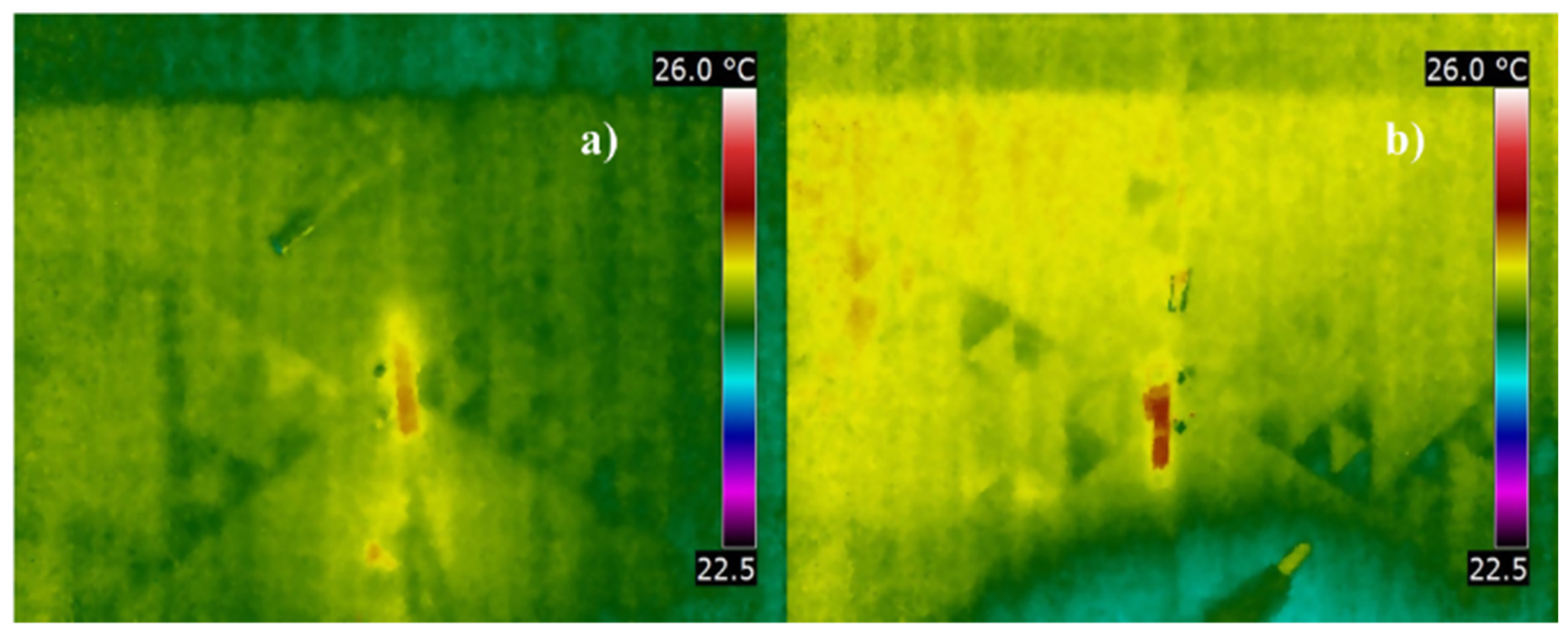
2.1. SWCNT Films as Bolometers
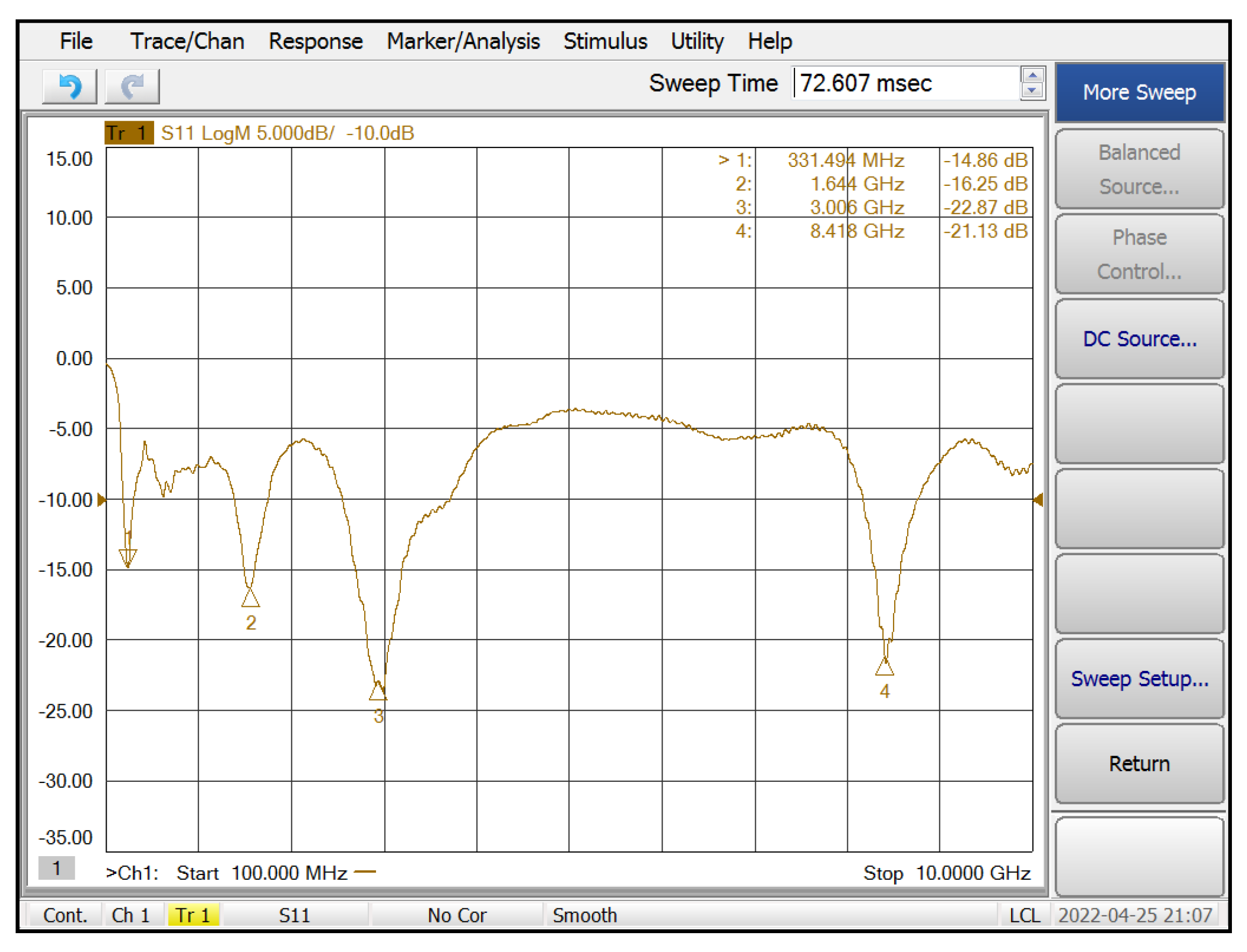
2.2. The Antenna-Coupled SWCNT Bolometers
2.3. Characterization Based on a Line-of-Sight UHF Link
3. Results and Discussion
Performance of Bolometers
4. Conclusions
Author Contributions
Funding
Acknowledgments
Conflicts of Interest
References
- Li, S.; Yu, Z.; Yen, S.F.; Tang, W.C.; Burke, P.J. Carbon nanotube transistor operation at 2.6 GHz. Nano Lett. 2004, 4, 753–756. [Google Scholar] [CrossRef]
- Rodriguez-Morales, F.; Zannoni, R.; Nicholson, J.; Fischetti, M.; Yngvesson, K.S.; Appenzeller, J. Direct and heterodyne detection of microwaves in a metallic single wall carbon nanotube. Appl. Phys. Lett. 2006, 89, 083502. [Google Scholar] [CrossRef] [Green Version]
- Tarasov, M.; Svensson, J.; Kuzmin, L.; Campbell, E.E.B. Carbon nanotube bolometers. Appl. Phys. Lett. 2007, 90, 163503. [Google Scholar] [CrossRef] [Green Version]
- Fu, K.; Zannoni, R.; Chan, C.; Adams, S.H.; Nicholson, J.; Polizzi, E.; Yngvesson, K.S. Terahertz detection in single wall carbon nanotubes. Appl. Phys. Lett. 2008, 92, 033105. [Google Scholar] [CrossRef] [Green Version]
- Itkis, M.E.; Borondics, F.; Yu, A.; Haddon, R.C. Bolometric infrared photoresponse of suspended single-walled carbon nanotube films. Science 2006, 312, 413–416. [Google Scholar] [CrossRef] [Green Version]
- Lu, R.; Shi, J.J.; Baca, F.J.; Wu, J.Z. High performance multiwall carbon nanotube bolometers. J. Appl. Phys. 2010, 108, 084305. [Google Scholar] [CrossRef]
- Ryger, I.; Lobotka, P.; Steiger, A.; Chromik, S.; Lalinsky, T.; Raida, Z.; Vanko, G. Uncooled Antenna-Coupled Microbolometer for Detection of Terahertz Radiation. J. Infrared. Milli. Terahz. Waves 2021, 42, 462–478. [Google Scholar] [CrossRef]
- García-Valdivieso, G.; Navarro-Contreras, H.R.; Vera-Reveles, G.; González, F.J.; Simmons, T.J.; Hernández, M.G.; Quintana, M.; Nieto Navarro, J.G. High sensitivity bolometers from thymine functionalized multi-walled carbon nanotubes. Sens. Actuators B Chem. 2017, 238, 880–887. [Google Scholar] [CrossRef]
- Kraus, H. Superconductive bolometers and calorimeters. Supercond. Sci. Technol. 1996, 9, 827–842. [Google Scholar] [CrossRef]
- Gonzalez, F.J.; Fumeaux, C.; Alda, J.; Boreman, G.D. Thermal impedance model of electrostatic discharge effects on microbolometers. Microw. Opt. Technol. Lett. 2000, 26, 291–293. [Google Scholar] [CrossRef]
- González, F.J.; Gritz, M.A.; Fumeaux, C.; Boreman, G.D. Two dimensional array of antenna-coupled microbolometers. Int. J. Infrared Millim. Waves 2002, 23, 785–797. [Google Scholar] [CrossRef]
- Kruse, P.W. Uncooled Thermal Imaging: Arrays, Systems, and Applications; SPIE Press: Washington, DC, USA, 2001. [Google Scholar]
- Chen, C.; Yi, X.; Zhang, J.; Zhao, X. Linear uncooled microbolometer array based on VOx thin films. Infrared Phys. Technol. 2001, 42, 87–90. [Google Scholar] [CrossRef]
- Mottin, E.; Martin, J.-L.; Ouvrier-Buffet, J.-L.; Vilain, M.; Bain, A.; Yon, J.-J.; Tissot, J.-L.; Chatard, J.-P. Enhanced amorphous silicon technology for 320 × 240 microbolometer arrays with a pitch of 35 μm. In Proceedings of the Infrared Technology and Applications XXVII; Andresen, B.F., Fulop, G.F., Strojnik, M., Eds.; SPIE: Orlando, FL, USA, 2001; Volume 4369, p. 250. [Google Scholar] [CrossRef]
- Ningyi, Y.; Jinhua, L.; Chan, H.L.W.; Chenglu, L. Comparison of VO2 thin films prepared by inorganic sol-gel and IBED methods. Appl. Phys. A Mater. Sci. Process. 2004, 78, 777–780. [Google Scholar] [CrossRef]
- González, F.J.; Ashley, C.S.; Clem, P.G.; Boreman, G.D. Antenna-coupled microbolometer arrays with aerogel thermal isolation. Infrared Phys. Technol. 2004, 45, 47–51. [Google Scholar] [CrossRef]
- Simón, J.; González, F.J. Nanoantennas for polarisation division multiplexing. Electron. Lett. 2011, 47, 120–121. [Google Scholar] [CrossRef]
- Kopylova, D.S.; Fedorov, F.S.; Alekseeva, A.A.; Gilshteyn, E.P.; Tsapenko, A.P.; Bubis, A.V.; Grebenko, A.K.; Popov, Z.I.; Sorokin, P.B.; Gladush, Y.G.; et al. Holey single-walled carbon nanotubes for ultra-fast broadband bolometers. Nanoscale 2018, 10, 18665–18671. [Google Scholar] [CrossRef]
- Gasper, M.R.; Toonen, R.C.; Hirsch, S.G.; Ivill, M.P.; Richter, H.; Sivarajan, R. Radio Frequency Carbon Nanotube Thin-Film Bolometer. IEEE Trans. Microw. Theory Tech. 2017, 65, 3278–3284. [Google Scholar] [CrossRef]
- Mehdipour, A.; Rosca, I.D.; Sebak, A.; Trueman, C.W.; Hoa, S.V. Full-Composite Fractal Antenna Using Carbon Nanotubes for Multiband Wireless Applications. IEEE Antennas Wirel. Propag. Lett. 2010, 9, 891–894. [Google Scholar] [CrossRef]
- Abbas, S.M.; Sevimli, O.; Heimlich, M.C.; Esselle, K.P.; Kimiaghalam, B.; Foroughi, J.; Safaei, F. Microwave Characterization of Car bon Nanotube Yarns For UWB Medical Wireless Body Area Networks. IEEE Trans. Microw. Theory Tech. 2013, 61, 3625–3631. [Google Scholar] [CrossRef] [Green Version]
- Alonso-Gonzalez, L.; Ver-Hoeye, S.; Fernadez-Garcia, M.; Vazquez-Antuna, C.; Las-Heras Andres, F. On the development of a novel mixed embroidered-woven slot antenna for wireless applications. IEEE Access 2019, 7, 9476–9489. [Google Scholar] [CrossRef]
- Vera-Reveles, G.; Simmons, T.J.; Bravo-Sánchez, M.; Vidal, M.A.; Navarro-Contreras, H.; González, F.J. High-sensitivity bolometers from self-oriented single-walled carbon nanotube composites. ACS Appl. Mater. Interfaces 2011, 3, 3200–3204. [Google Scholar] [CrossRef] [PubMed]
- Simmons, T.J.; Hashim, D.; Vajtai, R.; Ajayan, P.M. Large area-aligned arrays from direct deposition of single-wall carbon nanotube inks. J. Am. Chem. Soc. 2007, 129, 10088–10089. [Google Scholar] [CrossRef] [PubMed]
- Bravo-Sanchez, M.; Simmons, T.J.; Vidal, M.A. Liquid crystal behavior of single wall carbon nanotubes. Carbon N. Y. 2010, 48, 3531–3542. [Google Scholar] [CrossRef]
- Simmons, T.J.; Vera-Reveles, G.; González, G.; Gutiérrez Hernández, J.M.; Linhardt, J.L.; Navarro- Contreras, H.; González, F.J. Bolometric Properties of Semiconducting and Metallic Single-Walled Carbon Nanotube Composite Films. ACS Photonics 2015, 2, 334–340. [Google Scholar] [CrossRef]
- Puente-Baliarda, C.; Romeu, J.; Pous, R.; Cardama, A. On the behavior of the sierpinski multiband fractal antenna. IEEE Trans. Antennas Propag. 1998, 46, 517–524. [Google Scholar] [CrossRef] [Green Version]
- Gerald, E. Measure, Topology, and Fractal Geometry, 2nd ed.; Springer: New York, NY, USA, 1990. [Google Scholar]
- Puente, C.; Romeu, J.; Pous, R.; Garcia, X.; Benitez, F. Fractal multiband antenna based on the Sierpinski gasket. Electron. Lett. 1996, 32, 1–2. [Google Scholar] [CrossRef] [Green Version]
- Puente, C.; Borja, C.; Navarro, M.; Romeu, J. An iterative model for fractal antennas: Application to the Sierpinski gasket antenna. IEEE Trans. Antennas Propag. 2000, 48, 713–719. [Google Scholar] [CrossRef]
- Kaur, J.; Singh, S.; Kansal, A. Multiband behaviour of sierpinski fractal antenna. Res. J. Inf. Technol. 2011, 3, 35–43. [Google Scholar] [CrossRef] [Green Version]
- Best, S.R. On the significance of self-similar fractal geometry in determining the multiband behavior of the sierpinski gasket antenna. IEEE Antennas Wirel. Propag. Lett. 2002, 1, 22–25. [Google Scholar] [CrossRef]
- Tsachtsiris, G.F.; Soras, C.F.; Karaboikis, M.P.; Makios, V.T. Analysis of a modified Sierpinski gasket monopole antenna printed on dual band wireless devices. IEEE Trans. Antennas Propag. 2004, 52, 2571–2579. [Google Scholar] [CrossRef]
- Kapetanakis, T.N.; Pavec, M.; Ioannidou, M.P.; Nikolopoulos, C.D.; Baklezos, A.T.; Soukup, R.; Vardiambasis, I.O. Embroidered Βow-Tie Wearable Antenna for the 868 and 915 MHz ISM Bands. Electronics 2021, 10, 1983. [Google Scholar] [CrossRef]
- Rogalski, A. Infrared Detectors, 2nd ed.; CRC Press: Boca Raton, FL, USA, 2010. [Google Scholar]
- Balanis, C.A. Antenna Theory: Analysis and Design, 3rd ed.; Wiley: Hoboken, NJ, USA, 2016. [Google Scholar]
- Cengel, Y.A. Heat and Mass Transfer: A Practical Approach, 3rd ed.; McGraw-Hill: New York, NY, USA, 2006. [Google Scholar]
- Rajendra Kumar, R.T.; Karunagaran, B.; Mangalaraj, D.; Narayandass, S.K.; Manoravi, P.; Joseph, M.; Gopal, V. Study of a pulsed laser deposited vanadium oxide based microbolometer array. Smart Mater. Struct. 2003, 12, 188–192. [Google Scholar] [CrossRef]
- Ham, M.H.; Kong, B.S.; Kim, W.J.; Jung, H.T.; Strano, M.S. Unusually large Franz-Keldysh oscillations at ultraviolet wavelengths in single-walled carbon nanotubes. Phys. Rev. Lett. 2009, 102, 047402. [Google Scholar] [CrossRef] [PubMed]
- Ouyang, M.; Huang, J.L.; Cheung, C.L.; Lieber, C.M. Energy gaps in “metallic” single-walled carbon nanotubes. Science 2001, 292, 702–705. [Google Scholar] [CrossRef] [PubMed] [Green Version]
- García, M.; Ambrosio, R.; Torres, A.; Kosarev, A. IR bolometers based on amorphous silicon germanium alloys. J. Non-Cryst. Solids 2004, 338–340, 744–748. [Google Scholar] [CrossRef]


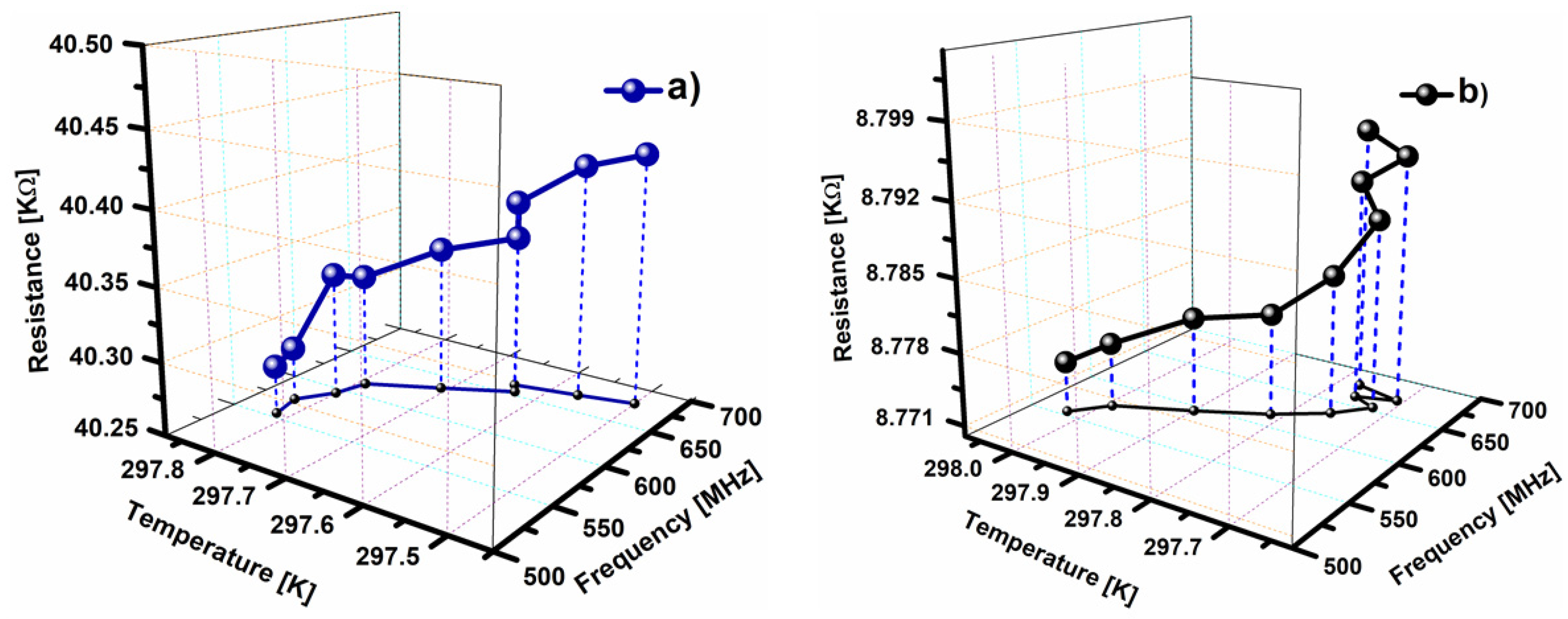
| Frequency (MHz) | Temperature (K) | Resistance (KΩ) | ||
|---|---|---|---|---|
| Uncracked Sample | Initial measurement | 554.5 | 297.81 | 40.283 |
| Final measurement | 678.5 | 297.50 | 40.424 | |
| Cracked Sample | Initial measurement | 554.5 | 298.02 | 8.775 |
| Final measurement | 678.5 | 297.72 | 8.796 |
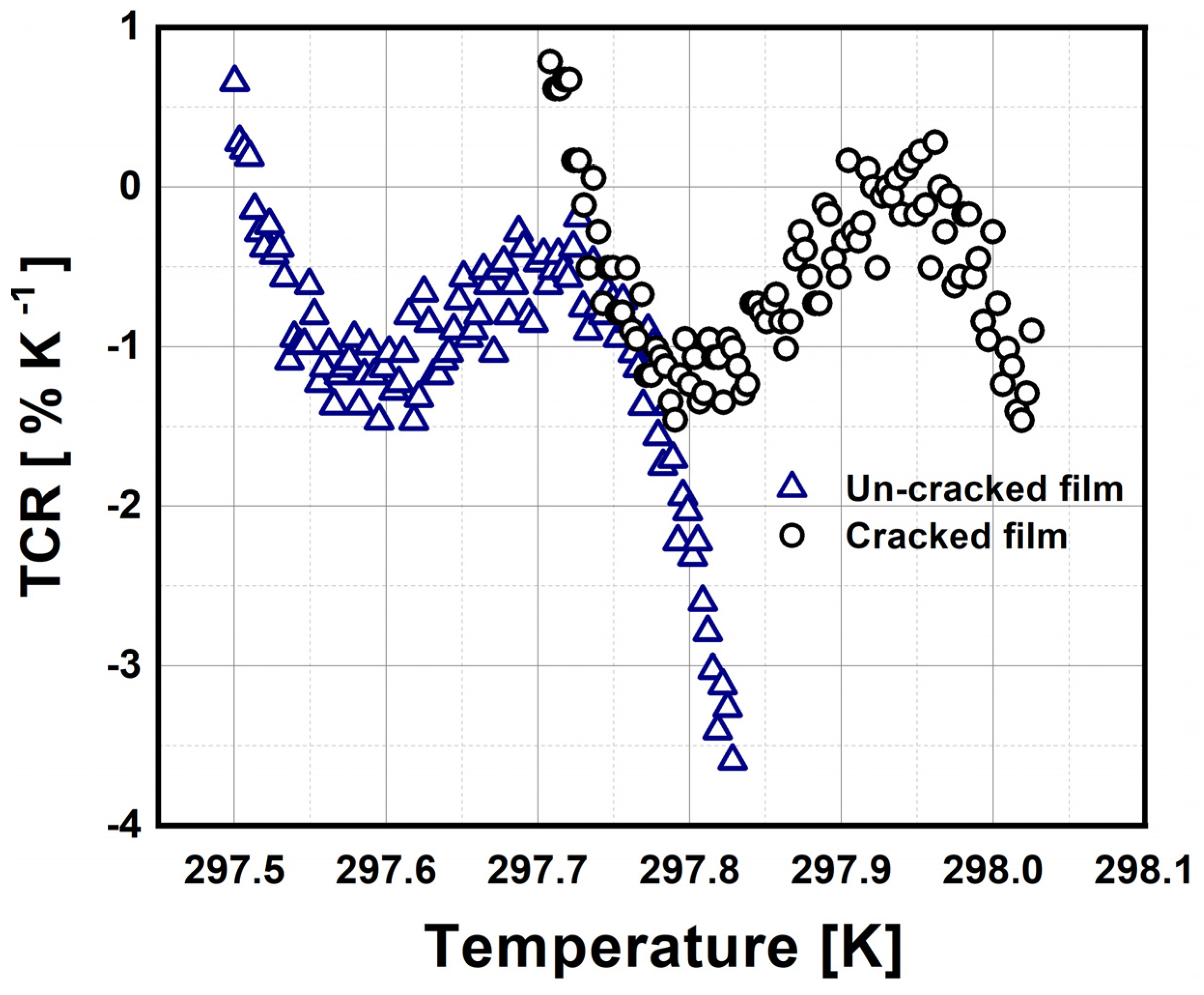
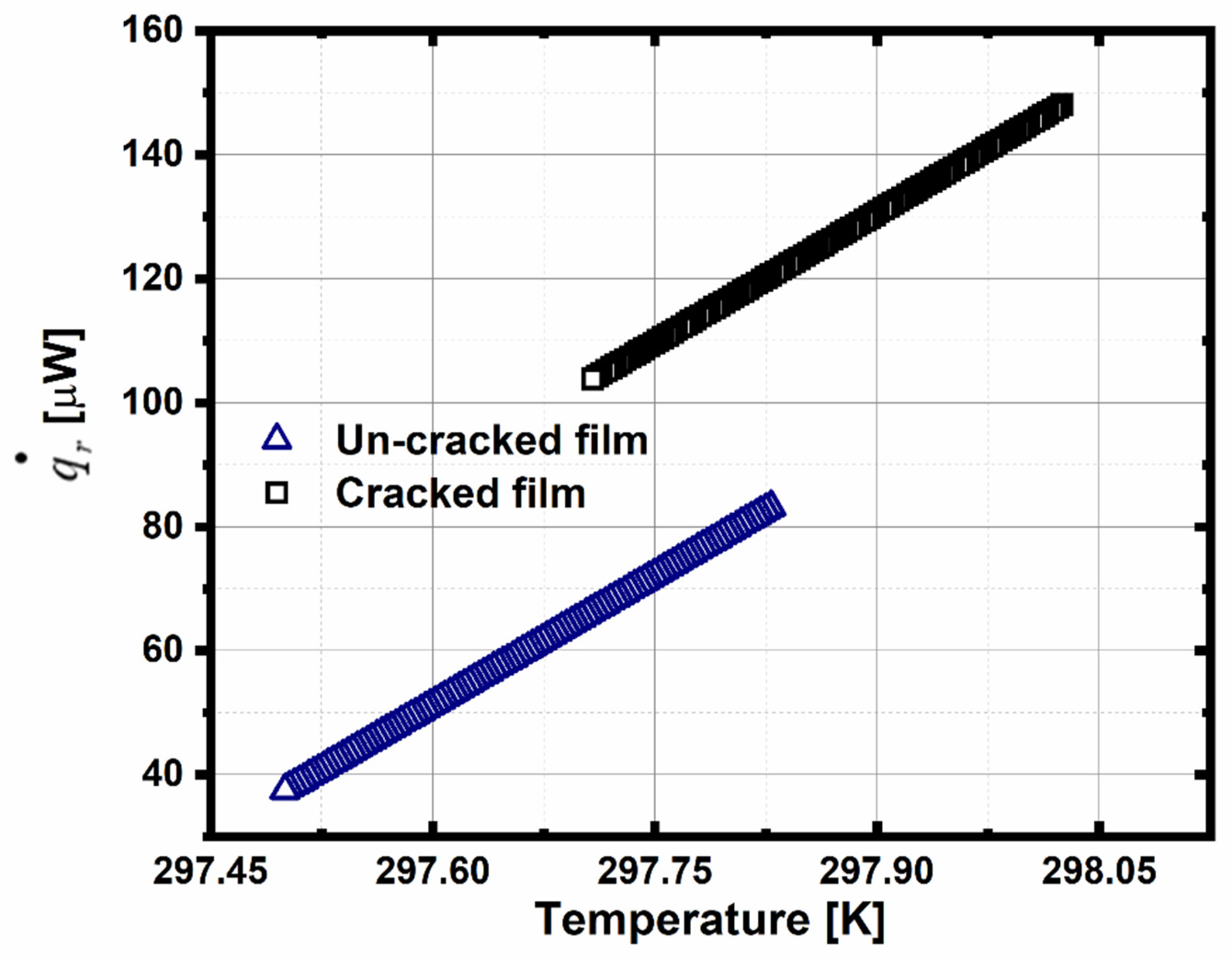
| SWCNT | Minimum Value of TCR (%K−1) ±SD | Temperature at Which TCR is Minimum (K) | Maximum Responsivity (V/W) | Maximum Radiation Heat (µW) | Electric Conductivity (µS m−1) |
|---|---|---|---|---|---|
| Uncracked | −3.6 ± 0.76 | 297.82 | 9.4 × 10⁻³ | 81.7 | 1.23 |
| Cracked | −1.46 ± 0.5 | 298.01 | 1.4 × 10⁻³ | 148.1 | 5.69 |
Publisher’s Note: MDPI stays neutral with regard to jurisdictional claims in published maps and institutional affiliations. |
© 2022 by the authors. Licensee MDPI, Basel, Switzerland. This article is an open access article distributed under the terms and conditions of the Creative Commons Attribution (CC BY) license (https://creativecommons.org/licenses/by/4.0/).
Share and Cite
Vera-Reveles, G.; González-Fernández, J.V.; Castillo-León, J.F.; González, F.J.; Díaz de León-Zapata, R.; de la Rosa-Zapata, A.B.; Orocio-Castro, N.; Simón, J. Tuning Bolometric Parameters of Sierpinski Fractal Antenna-Coupled Uncracked/Cracked SWCNT Films by Thermoelectric Characterization at UHF Frequencies. Electronics 2022, 11, 1665. https://doi.org/10.3390/electronics11111665
Vera-Reveles G, González-Fernández JV, Castillo-León JF, González FJ, Díaz de León-Zapata R, de la Rosa-Zapata AB, Orocio-Castro N, Simón J. Tuning Bolometric Parameters of Sierpinski Fractal Antenna-Coupled Uncracked/Cracked SWCNT Films by Thermoelectric Characterization at UHF Frequencies. Electronics. 2022; 11(11):1665. https://doi.org/10.3390/electronics11111665
Chicago/Turabian StyleVera-Reveles, Gustavo, José Vulfrano González-Fernández, Juan Francisco Castillo-León, Francisco Javier González, Ramón Díaz de León-Zapata, Ariel Benjamín de la Rosa-Zapata, Norma Orocio-Castro, and Jorge Simón. 2022. "Tuning Bolometric Parameters of Sierpinski Fractal Antenna-Coupled Uncracked/Cracked SWCNT Films by Thermoelectric Characterization at UHF Frequencies" Electronics 11, no. 11: 1665. https://doi.org/10.3390/electronics11111665