Article

A Passive but Local Active Memristor and Its Complex Dynamics

1
Institute of Modern Circuits and Intelligent Information, Hangzhou Dianzi University, Hangzhou 310018, China
2
School of Mechanical Engineering, Hangzhou Dianzi University, Hangzhou 310018, China
*
Author to whom correspondence should be addressed.
Electronics 2022, 11(12), 1843; https://doi.org/10.3390/electronics11121843
Submission received: 12 May 2022 / Revised: 6 June 2022 / Accepted: 6 June 2022 / Published: 9 June 2022
(This article belongs to the Special Issue Memristive Devices and Systems: Modelling, Properties & Applications)

Abstract

:
This paper proposes a globally passive but locally active memristor, which has three stable equilibrium points and two unstable equilibrium points, exhibiting two stable locally active regions and four unstable locally active regions. We find that when the memristor operates in a stable local active region, the memristor-based second-order circuit with a parallel capacitor or a series inductor can produce periodic oscillation. Moreover, the memristor-based third-order circuit with two energy storage elements, a capacitor and an inductor, can produce complex chaotic oscillation, forming the simplest chaotic circuit.

1. Introduction

According to Chua’s theory of local activity [1], all memristors can be classified into either locally passive memristors or locally active memristors. A subset of locally active memristors have the ability to exhibit fascinating phenomena and attributes, such as periodic oscillation, chaotic oscillation, and even action potentials and artificial intelligence. Relevant research on locally active memristors may help us to promote the applications of memristors in artificial neural networks, memristor oscillation circuits, chaos circuits, and so on.
Chua proposed a locally active memristor model named Chua Corsage memristor (CCM) [2], which has two stable equilibrium points and a locally active domain, and is, therefore, a nonvolatile local active memristor. Based on the CCM, a second-order periodic oscillation circuit was carried out via the small-signal circuit analysis method [3]. It was found that the circuit parameters and bias voltage can cause Hopf bifurcation, which, in turn, leads to periodic oscillation. Subsequently, a four-lobe (a section of the DC V–I curve of the memristor that looks like a lobe) Chua Corsage memristor [4] and a six-lobe Chua Corsage memristor [5] were proposed respectively.
As the state equations of the three locally active CCMs are based on the piecewise linear functions, they are globally passive but locally active memristors. The number of lobes of CCM increases with its stable equilibrium points. However, due to the nondifferentiable points of the state function, there is only one locally active region obtained. Moreover, the correlation between multiple stability and local active properties has not been discussed.
References [6,7] proposed two voltage-controlled locally active memristor models and found that chaotic oscillations occurred in the constructed memristor circuits. Reference [8] combined a piecewise function with a polynomial to construct a globally passive but locally active memristor, which has two locally active regions, and found that chaotic oscillation occurred in its locally active region. Reference [9] constructed a current-controlled S-type locally active memristor model based on the existing memristor physical devices.
To identify the correlation between the local active characteristics and the complex dynamic behaviors of a memristor, this paper designs a globally passive but locally active memristor model with a continuous state function and three-valued stability, and explores the correlation between the multi-stability and the locally active regions of the memristor. Based on this, we construct two chaotic circuits using the quantitative method rather than trial-and-error, and analyze their complex dynamics, illustrating the mechanism of the Hopf bifurcation caused by passive parameters connected to the memristor.

2. A Six-Lobe Locally Active Memristor with a Continuous and Derivable State Equation

Based on Chua’s unfolding theorem [10], we propose a six-lobe locally active memristor with a continuous and derivable state equation, which is a voltage-controlled extended memristor. The state-dependent Ohm’s law and its state equation related to the internal state variable x of the memristor are written as follows:
{ i = G ( x ) v d x d t = f ( x , v ) = k 2 ( γ ( x ) + α ( x ) β ( v ) )
where G ( x ) = k 1 ( a x 2 + b x + c ) , α ( x ) = a 1 + a 2 x + a 3 x 2 , β ( v ) = v and
γ ( x ) = { k 3 n = 1 ( 1 ) n ( 2 n + 1 ) ( 2 n ) ( 2 n 1 ) x 2 n 2 ,   0 | x | 1 k 3 n = 1 ( 1 ) n ( 2 n + 1 ) ( 2 n ) ( 2 n 1 ) ( 1 x ) 2 n 2 ,   | x | > 1 .
To make the memristor model globally passive, the function G(x) must be nonnegative for all real numbers x. Therefore, the parameters need to satisfy a > 0 and b2 − 4ac < 0, where we set the parameters: a = 1, b = 0, and c = 0.1. We adjust the order of magnitude of the memristance with the parameter k so that it matches the actual memristor, where we take k = 10−3, while parameter k2 is used to control the change rate of state variable x. If k2 = 103, the variable rate agrees with the actual memristors. As there is no solution if α(x) = 0 when calculating stable equilibrium points of the memristor on its DC V–I curve, we set α(x) ≠ 0, i.e., a3 ≠ 0 and a22 − 4a1a3 < 0, where we set a1 = 3, a2 = 0.2, and a3 = 0.1.
When the memristor is power-off, the rate of change of the state variable x is γ(x), which is only related to the memristor itself and is called “internal force”. When a voltage is applied to the memristor, function f(x, v) is increased by an “external force”, α(x)β(v). We also introduce parameter k3 for balancing the effect of internal force and external force, where k3 = 0.05. In addition, γ(x) can be written as a continuous function γ(x) = −k3((48x5 − 480x3 + 240x)/(1 + x2)5).

2.1. Dynamic Route Map of the Memristor

The dynamic route map is one of the important methods to explore the dynamic properties of nonlinear equations [11], which can be used to analyze memory characteristics and switch characteristics of memristors. Figure 1 shows five dynamic routes of the proposed memristor, each parametrized by a value of the memristor voltage v, where v = −0.6 V, −0.3 V, 0 V, 0.3 V, and 0.6 V, respectively.
In Figure 1, the dynamic route with v = 0 is called the Power Off Plot (POP), which has five intersections with the horizontal axis (Q1 to Q5), in which the state variable x is stable at Q1, Q3, and Q5 but unstable at Q2 and Q4. When the memristor is power-off, the state variable x gradually stabilizes to Q1 (−3.0777, 0) or Q3 (0, 0) or Q5 (3.0777, 0). Observe that when the absolute value of the state variable x increases, the rate of change of the state variable x, i.e., dx/dt, tends to zero asymptotically.

2.2. Hysteresis Characteristics of Memristor

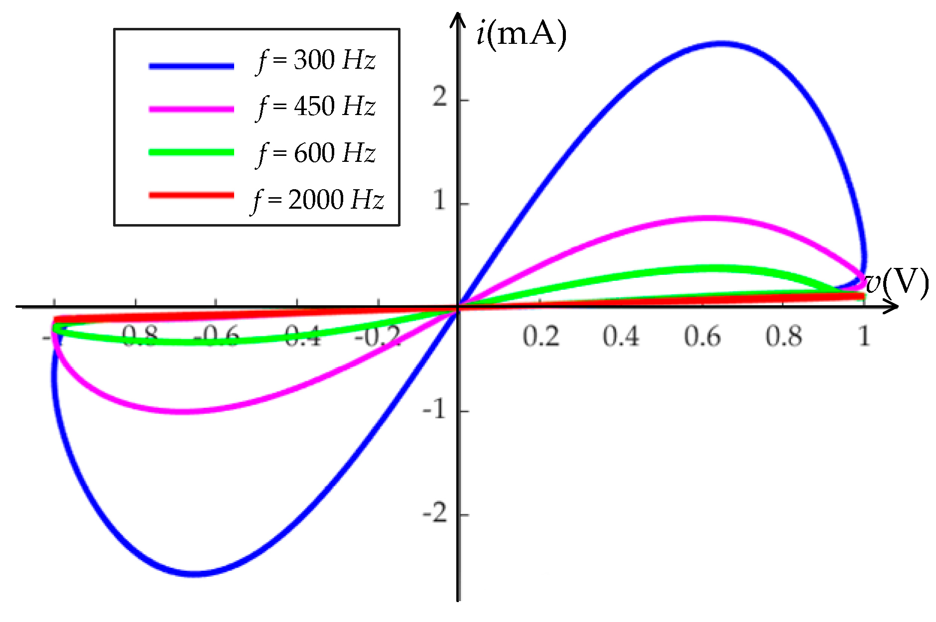
Driven by the zero-bias AC power, the relationship between the voltage and the current through the memristor has hysteresis characteristics and pinches with the increase in the frequency of the AC power [12]. Applying the voltage v(t) = 2Asin(2πft) with A = 1 V and different frequencies f at both ends of the memristor, if the initial state value x(0) = 0, the current response of the memristor is shown in Figure 2, which is a hysteresis loop and located in the first and third quadrants of the plane coordinate. If the frequency of the power is greater than 2 kHz, the curve coincides with a straight line with a slope of 10−4, and the memristor is equivalent to a linear resistor with a resistance of 104 Ohms. Therefore, the model is consistent with the characteristics of a memristor [13].

2.3. Local Activity

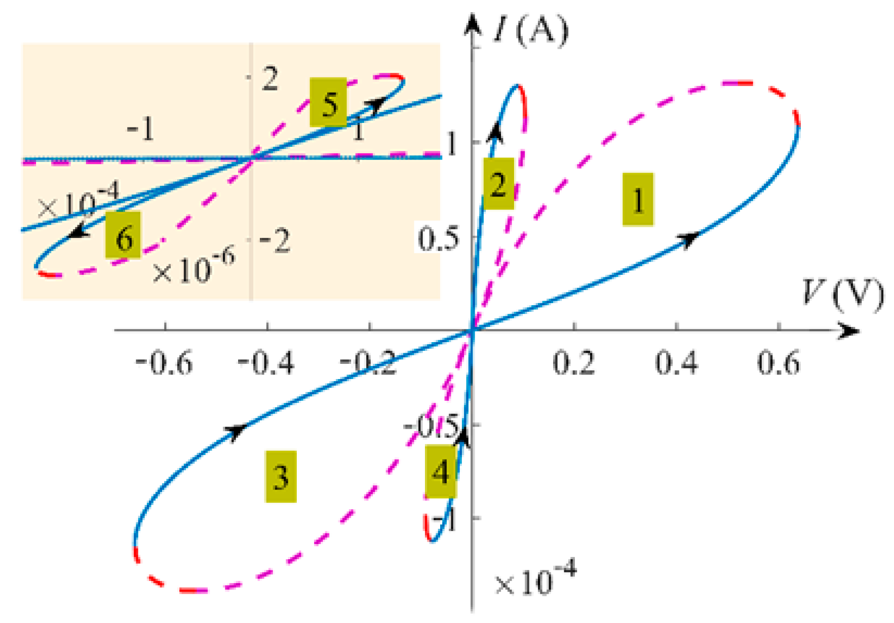
The local activity of the memristor is analyzed to determine whether the memristor can amplify small signals at some DC operating points. Based on a given DC voltage V, we solve the equation f(x,V) = 0 to obtain the solution of x and calculate the corresponding current I of the memristor. Then, the DC V–I curve of the memristor can be obtained by drawing the point set of the voltage V and the corresponding current I on the VI coordinate plane, as shown in Figure 3.
Observe from Figure 3 that the DC VI curve has six unique, smooth, and continuous lobes, and each lobe has a locally active region. All lobes are marked with numbers from 1 to 6, in which the red curve represents the negative differential resistance region of the memristor. The arrow indicates the increasing direction of state variable x, the real line segment indicates that the operating points on it are stable, and the dotted line segment indicates that the operating points on it are unstable. Observe also that the DC VI curve of the memristor is distributed in the first and third quadrants of the coordinate plane, which shows that the memristor is globally passive but locally active. Table 1 shows the value range of six locally active regions.

3. Small-Signal Analysis for Locally Active Region

Locally active regions have the potential to amplify infinitely small signals and therefore can generate complex phenomena, such as periodic oscillation, chaotic oscillation, and even action potentials after assembling passive circuit components [14,15]. Small-signal analysis of a locally active region is helpful to explore its complex dynamic behaviors.

3.1. Zero-Pole Analysis of Memristor

Small-signal analysis is used to approximate the local dynamic behavior of the nonlinear memristor via its associated linearized equations. Let the DC voltage and current at an operating point Q be V and I, respectively. Assume that there is a voltage increment δv at the operating point Q(V, I), and the resulting rate of current change di/dt obtained from Equation (1) is
d i d t = i x d x d t + i v d v d t = a 11 d x d t + a 12 d v d t ,
where a11(Q) = ∂i/∂x = 2xv/1000 and a12(Q) = ∂i/∂v = (x2 + 0.1)/1000. Furthermore, the operating point Q(V, I) on the DC V–I curve must meet the condition dx/dt = g(x,v). Through differential expansion of the state equation dx/dt = g(x,v) in Equation (1), we obtain
d ( d x d t ) d t = b 11 ( Q ) d x d t + b 12 ( Q ) d v d t
where b 11 ( Q ) = g ( x , v ) x | Q = γ ( x ) x + α ( x ) x × β ( v ) and b 12 ( Q ) = g ( x , v ) v | Q = α ( x ) .
Applying the Laplace transformation to (2) and (3), we have
{ i ^ ( s ) = a 11 ( Q ) x ^ ( s ) + a 12 ( Q ) v ^ ( s ) s x ^ ( s ) = b 11 ( Q ) x ^ ( s ) + b 12 ( Q ) v ^ ( s )
Solving Equation (4), the small-signal-equivalent admittance function Y(s, Q) about Q(V, I) is obtained as
Y ( s , Q ) = i ^ ( s ) / v ^ ( s ) = a 11 ( Q ) b 12 ( Q ) / ( s b 11 ( Q ) ) + a 12 ( Q )
By rearranging (5), the admittance function can be equivalent to
Y ( s , Q ) = 1 / ( s L x + R x ) + 1 / R y
where Lx = 1/(a11(Q)b12(Q)), Rx = b11(Q)/(a11(Q)b12(Q)), and Ry = a12(Q).
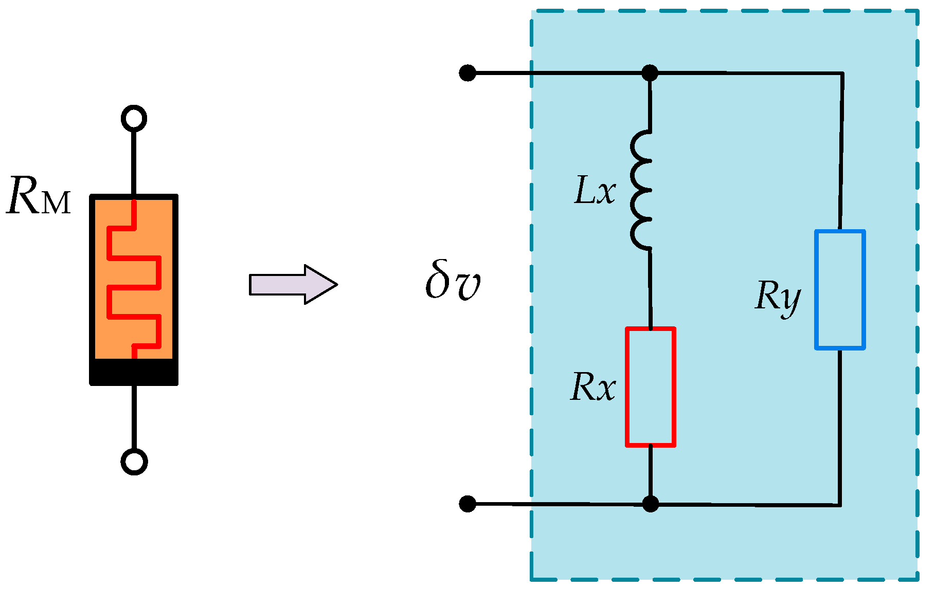
Figure 4 shows the equivalent circuit of the memristor at operating point Q(V, I). We find by calculation that Rx < 0 and Ry > 0 in the locally active regions, and Lx < 0 for the stable locally active points, while Lx > 0 for the unstable locally active points.
Through the zero-pole simplification of admittance function Y(s, Q), the small-signal admittance Y (s, Q) in terms of the pole s = P and the zero s = Z can be recast as
Y ( s , Q ) = K ( s Z ) / ( s P )
where K = a12(Q), Z = (a12(Q)b11(Q) − a11(Q)b12(Q))/a12(Q), and P = b11(Q).
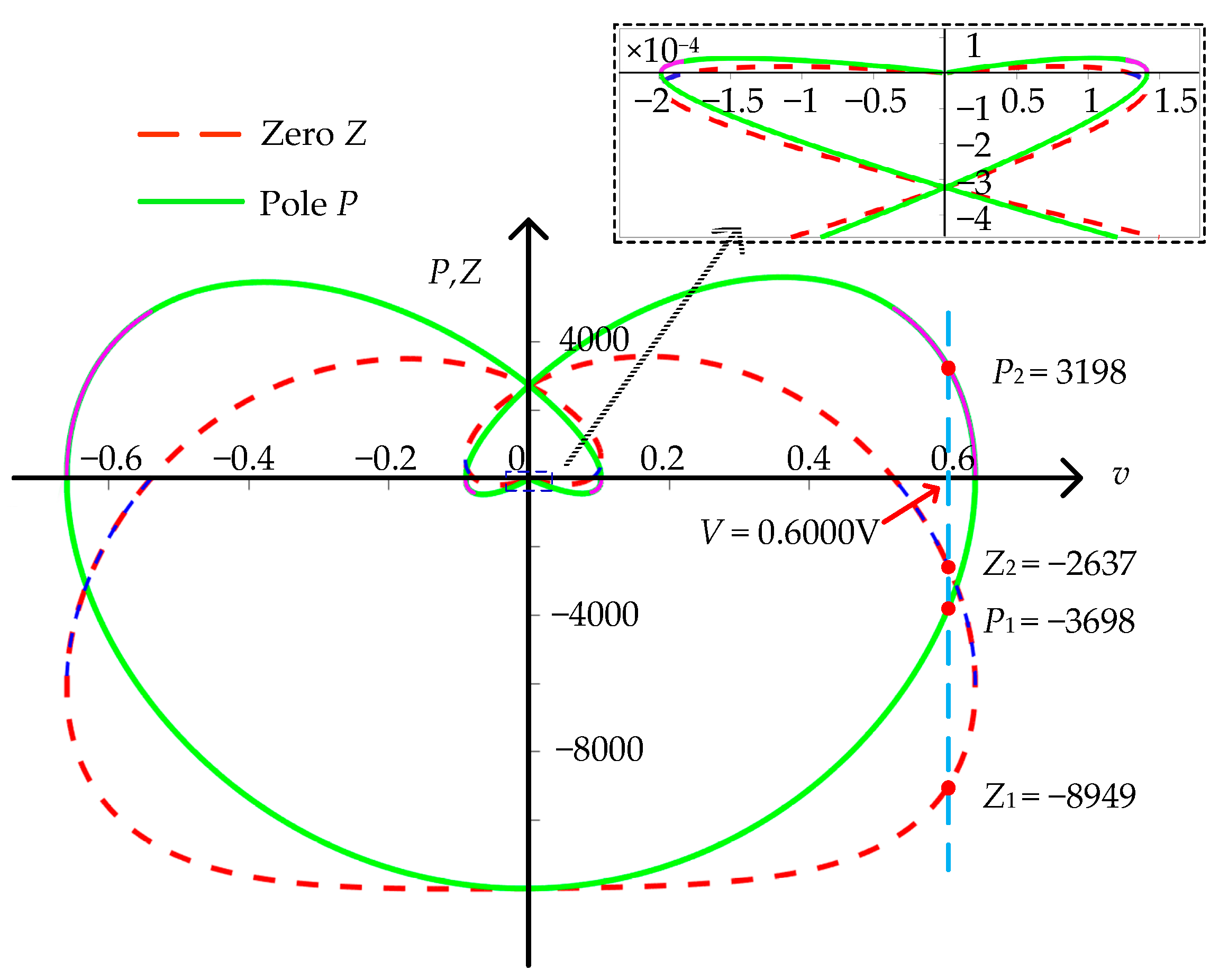
Figure 5 shows the pole and the zero trajectories of the admittance function Y(s, Q) with respect to the voltage V, where the solid and the dotted lines represent the poles and zero, respectively. The purple dotted line segment on the pole curve and the blue dotted line segment on the zero curve represent the zero and pole values of the memristor in the locally active regions, respectively. Obviously, P > 0 and Z < 0 for the stable locally active regions, while P < 0 and Z > 0 for the unstable locally active regions.

3.2. Frequency Response of the Memristor

From Equation (7), the frequency response of the memristor can be written as:
Y ( i ω , Q ) = K ( i ω Z ) / ( i ω P ) = ( K ( ω 2 + PZ ) + i K ω ( Z P ) ) / ( ω 2 + P 2 )
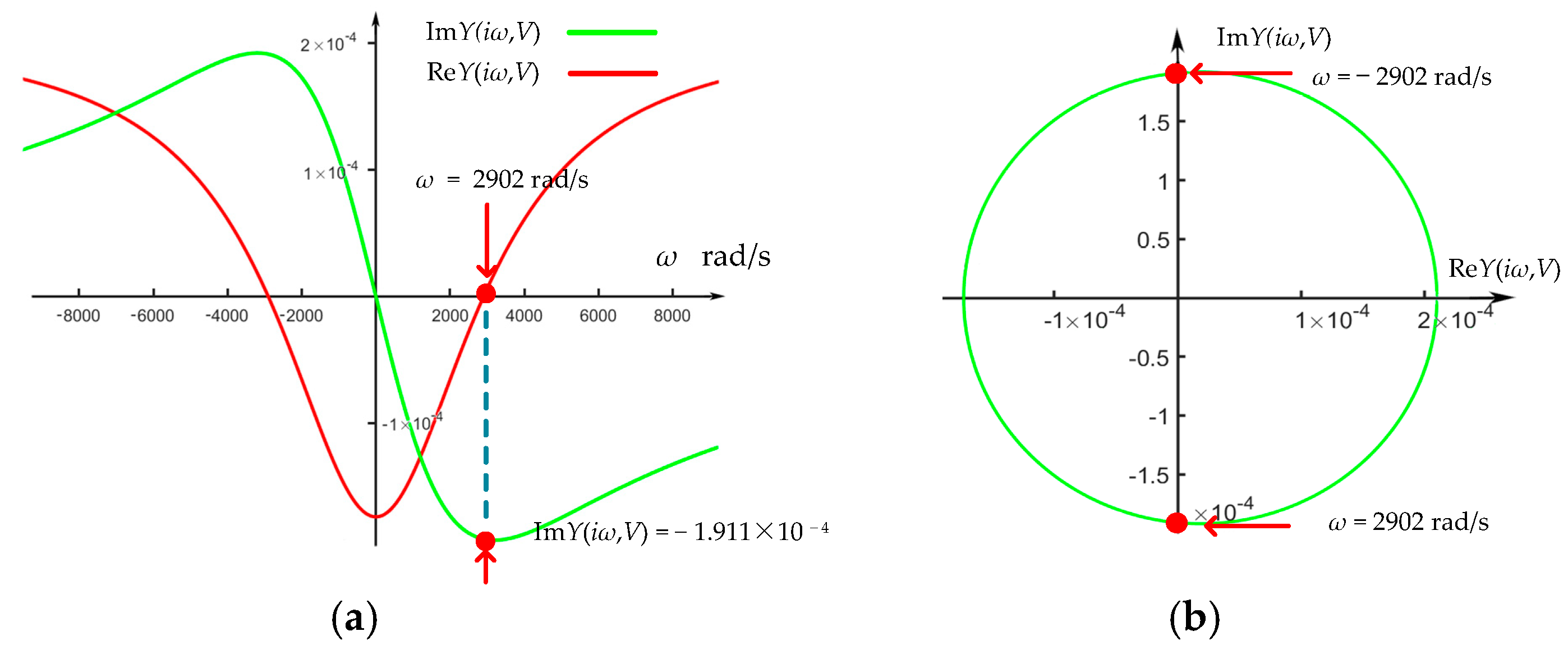
At equilibrium point V = V0, the real part and imaginary part of the memductance function are ReY(,V) = K(ω2 + pz)/(ω2 + p2) and ImY(,V) = iKω(zp)/(ω2 + p2), respectively. To make the locally active system generate oscillation, there should be a pair of complex conjugate poles (Hopf bifurcation points) on the imaginary axis for the admittance function Y(s, Q) of the locally active memristor. In other words, it is necessary to add an energy storage element (capacitance or inductance) in series or in parallel with the memristor to form a locally active system. The selection of capacitance or inductance depends on the frequency response of the memristor. Figure 6 shows the frequency response of the memristor where the voltage at both ends of the memristor is 0.6000 V. In order to construct an oscillation system, if Lx < 0 (Lx > 0) in the equivalent circuit of the memristor shown in Figure 4, an inductance L* = 1/(ωImY(,V)) (capacitor C* = ImY(,V)/ω) in series (parallel) with the memristor is required.
Figure 6 shows the frequency response of ReY(,V) and ImY(,V), where V = 0.6 V. Observe that ReY(*,V) = 0 and ImY(*,V) = −1.911 × 10⁻⁴ S at ω* = 2902 rad/s, indicating that the memristor is inductive and therefore a positive capacitance C* in parallel with the memristor is needed to compensate the ImY(*,V), as well as to make the total impedance of the C*-augmented memristive circuit equal to zero at operating point V = 0.6000 V. The compensated capacitance can be obtained using the following formula:
C* = −ImY(iω*,V)/ω* = 65.84 nF
Figure 7 shows the frequency response of ReY(,V) and ImY(,V), where V = 0.1031 V. Observe that ReY(*,V) = 0 and ImY(*,V) = −1.911 × 10⁻⁴ S at ω* = 200.7 rad/s, indicating that the memristor is capacitive and therefore a positive inductance L* in series with the memristor is needed to compensate the ImY(,V), as well as to make the total impedance of the L*-augmented memristive circuit equal to zero at operating point V = 0.1031 V. The compensated inductance can be obtained using the following formula:
L* = 1/(ω*ImY(,V)) = 1.972 H
Using the above small-signal-equivalent circuit method, we analyze the properties of the six local active regions of the memristor and obtain the following results shown in Table 2, which includes the small-signal-equivalent inductance, zero, pole, and the compensating energy storage element to cause the memristor oscillation.

4. Second-Order Periodic Circuit of Memristor

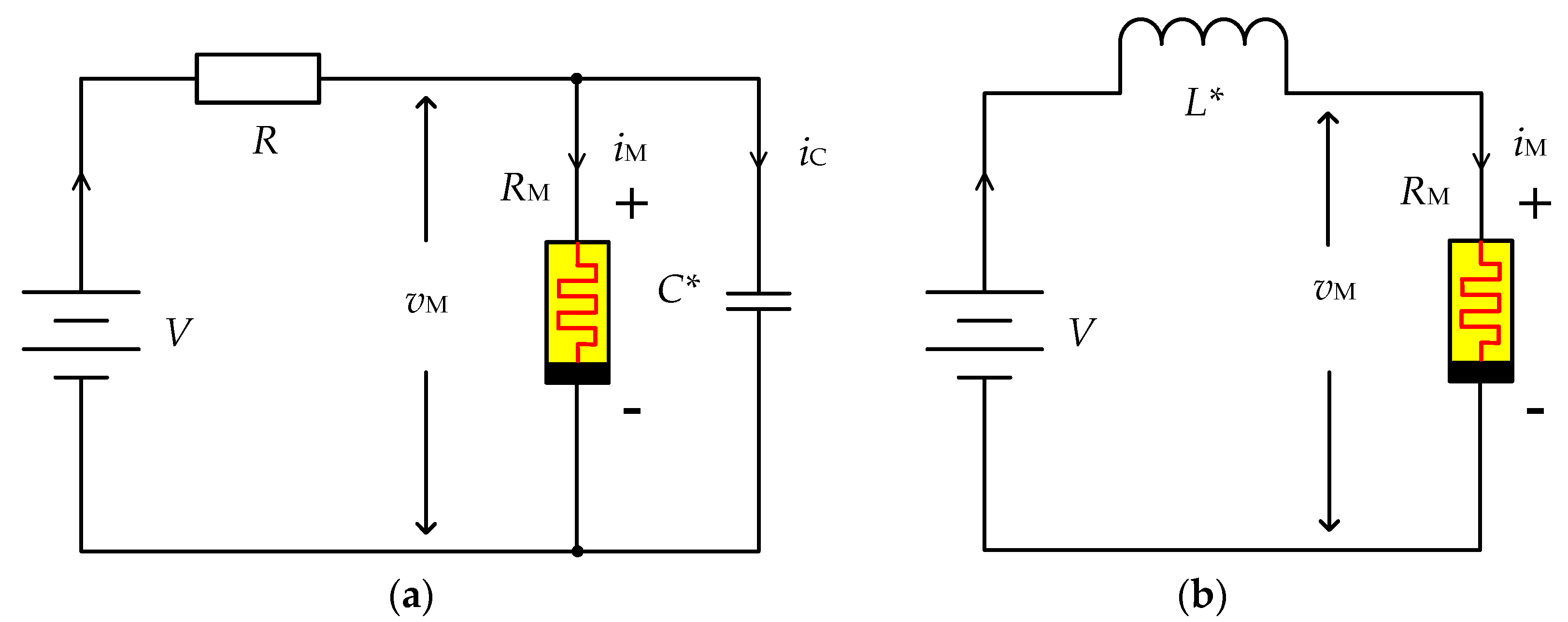
The above analysis shows that the memristor has two different types of locally active regions with deferent small-signal circuits, namely Lx < 0 and Lx > 0. For the two cases, we design two second-order memristive circuits, as shown in Figure 8.

4.1. Properties of the Memristive Circuit in the Unstable Locally Active Region of the Memristor

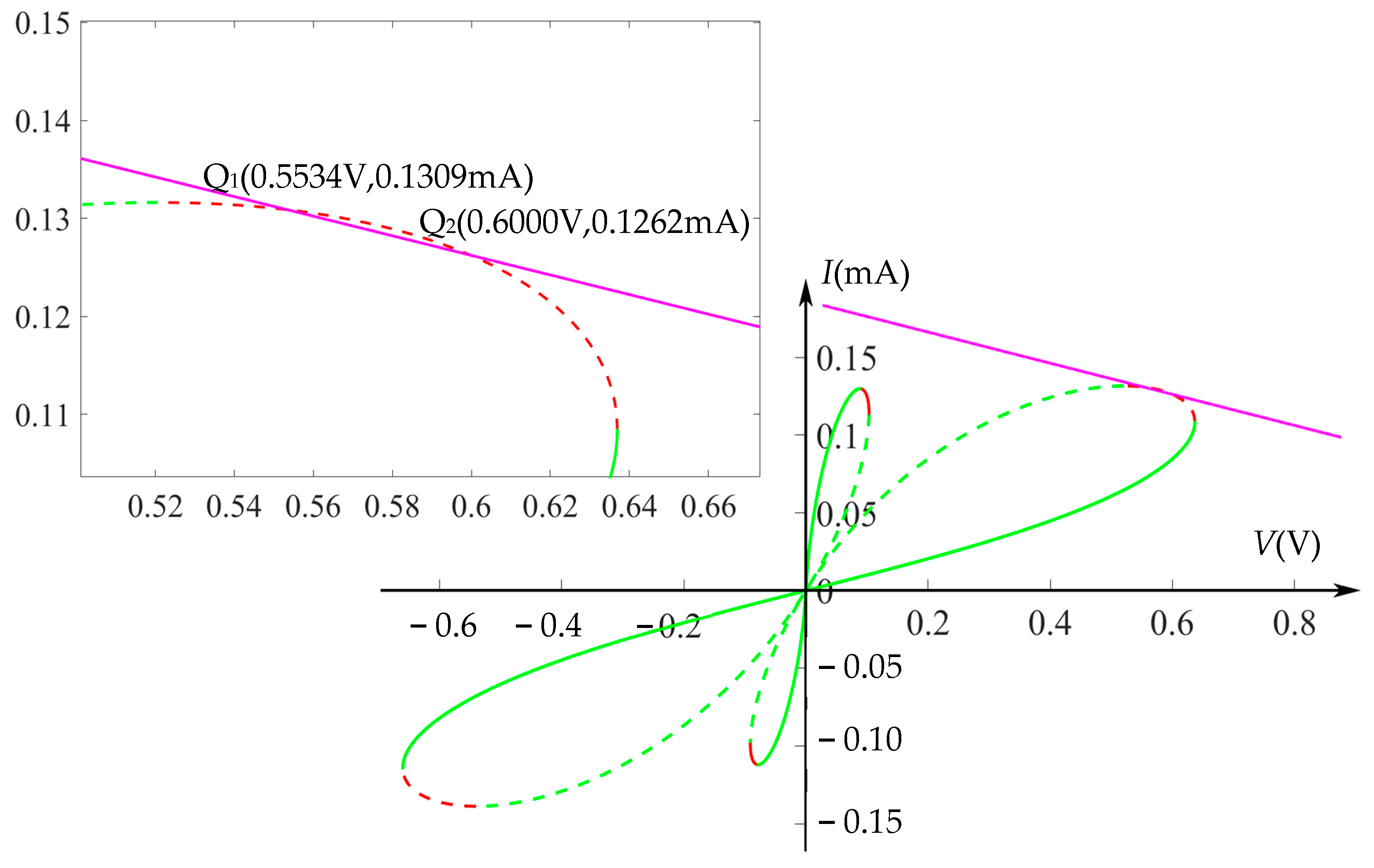
The memristive circuit shown in Figure 8a corresponds to the first unstable locally active region of the memristor, where R is a segregation resistor or load resistor, which provides an AC path for the memristor and also stabilizes the memristor at a certain operating point Q2, as shown in Figure 9.
Through small-signal analysis of the memristor oscillation circuit in Figure 8a, the composite admittance YC(s, Q) of the circuit satisfies that 1/YC(s, Q) = 1/(Y(s, Q) + YC*) + R, where YC* = sC*. Therefore, YC (s, Q) can been written as follows:
Y C ( s , Q ) = C s 2 + ( k p C ) s k z R C s 2 ( p R C 1 + k R ) s p k z R = ( s s z 1 ) ( s s z 2 ) ( s s p 1 ) ( s s p 2 ) R
The zeroes and the poles of the composite admittance YC(s, Q) of the circuits are obtained from Equation (9) as follows:
{ p 1 = a 1 + a 1 2 4 a 2 2 , p 2 = a 1 a 1 2 4 a 2 2 z 1 = b 1 + b 1 2 4 b 2 2 , z 2 = b 1 b 1 2 4 b 2 2
where a1 = (kR + 1 − pRC)/RC, a2 = −(p + kzR)/RC, b1 = (kpC)/RC, and b2 = −kz/RC; p, z, and k are the pole, the zero, and the coefficient of admittance function Y(s, Q) of the memristor in Equation (7), respectively.
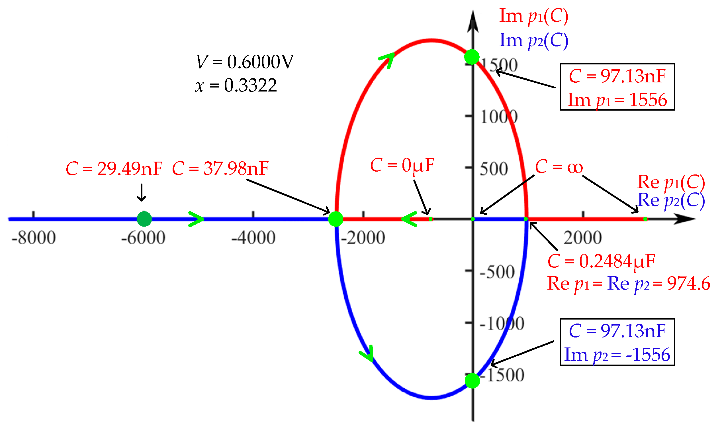
Figure 10 shows the loci of the real parts versus imaginary parts of the poles (P1 and P2) of YC(s, Q) with respect to the capacitance C, in which V = 0.6 V and the state variable x = 0.3322. Observe from Figure 10 that YC(s, Q) has a pair of complex conjugate poles on the imaginary axis at C = 97.13 nF and Im p1,2 = ±1556, which are the Hopf bifurcation parameters. When C < 97.13 nF, such as C = 65.84 nF, the real parts of the complex conjugate poles are less than zero, and the circuit gradually stabilizes to an equilibrium point, as shown in Figure 10a. However, when C = 97.13 nF, the periodic oscillation shown in Figure 10b,c occurs in the circuit. Moreover, the oscillation amplitude increases with the initial value, as described in Figure 10d. If C > 97.13 nF, the system enters the unstable right half plane of the complex plane and may oscillate.
Figure 11 shows the loci of the real parts versus imaginary parts of the poles (p1 and p2) of YC(s, Q) with respect to the voltage V, where C = 97.13 nF. Observe that YC(s, Q) has a pair of complex conjugate poles on the imaginary axis at the Hopf bifurcation parameters: V = 0.6 V and Im p1,2 = ±1556.
From Figure 11 and Figure 12, we find that the Hopf bifurcation frequency ωH = 1556 rad/s and the system oscillation frequency ωC = 2π/4.000 ms = 1570 rad/s through numerical calculation. It follows that ωC is consistent with the expected oscillation frequency ωH.

4.2. Properties of the Memristive Circuit in the Stable Locally Active Region of the Memristor

For Figure 8b, the composite admittance YC(s, Q) of the circuit satisfies
1 Y L ( s , Q ) = 1 Y ( s , Q ) + 1 Y L *
where YL* = 1/sL*. Therefore, YC(s, Q) can be written as follows:
Y L ( s , Q ) = K ( s Z ) L K s 2 ( K Z L 1 ) s P = ( s Z ) ( s s p 1 ) ( s s p 2 ) L
where P, Z, and K are the pole, the zero, and the coefficient of admittance function Y(s, Q) of the memristor in Equation (7), respectively.
The zero and the poles of the composite admittance of the circuit are obtained from Equation (11) as follows:
{ s p 1 = a 3 + a 3 2 4 a 4 2 , s p 2 = a 3 a 3 2 4 a 4 2 s z = z
where a3 = (1 − KZL)/KL and a4 = −P/KL.
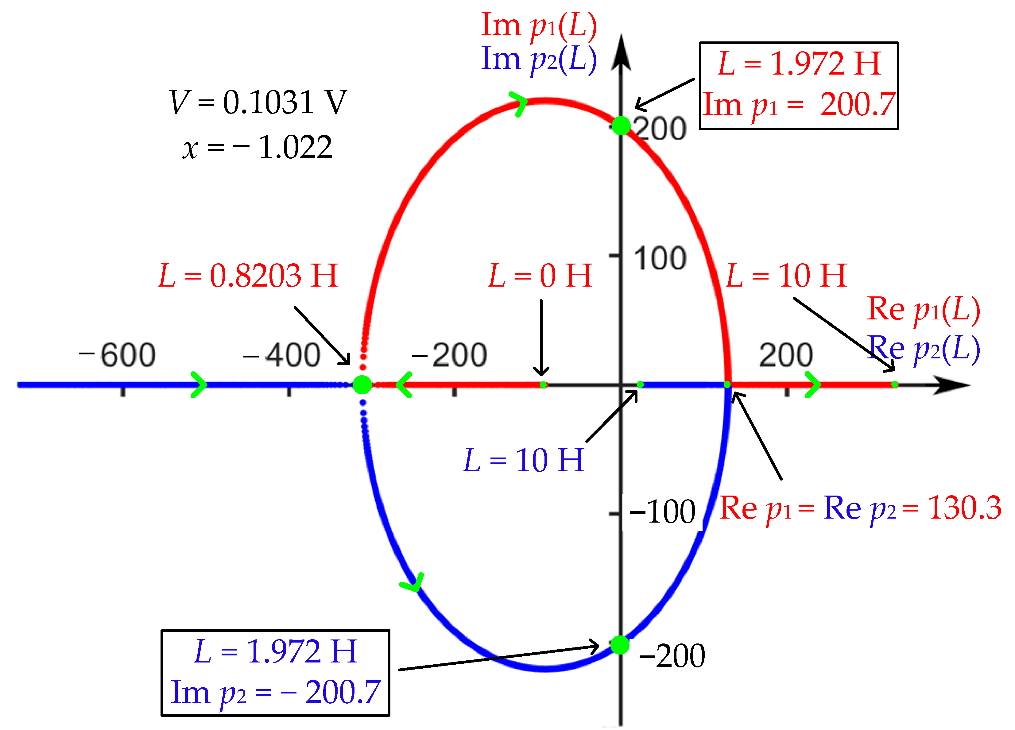
Figure 13 depicts the loci of the real and imaginary parts of the poles (P1 and P2) of the admittance YL(s, Q) versus the inductance L, where V = 0.1031 V and x = −1.022. Observe that L = 1.972 H is the Hopf bifurcation point of the memristive circuit where Im p1,2 = ±200.7. If L > 1.972 H, the system enters the right half plane of the complex plane and may oscillate; for example, for L = 2.021 H, a periodic oscillation appears as shown in Figure 14.
Figure 15 shows the loci of the real and imaginary parts of the poles (p1 and p2) of the admittance YL(s, Q) versus the voltage V, where L = 1.972 H.
Based on the Hopf bifurcation frequency ωH = 200.7 rad/s in Figure 13 and Figure 15, the system oscillation frequency can be calculated as ωL = 2π/0.031 s = 202.5 rad/s through circuit simulation, where ωL is consistent with the expected oscillation frequency ωH.

5. Memristor-Based Third-Order Chaotic Circuit

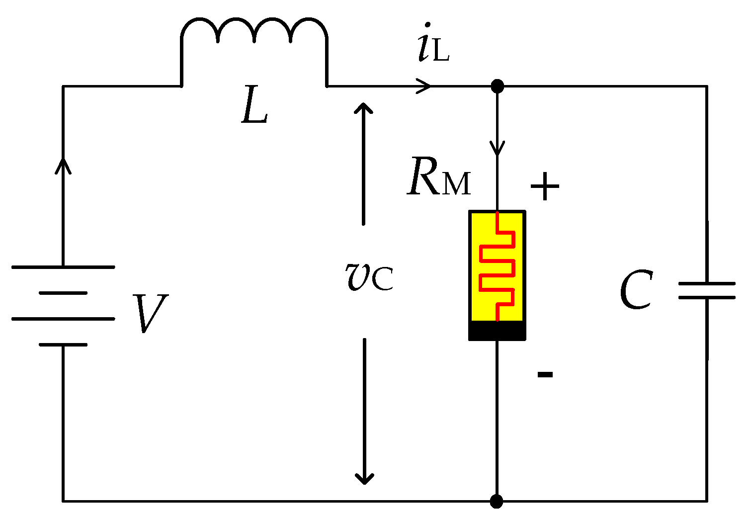
Based on the second-order memristive circuit shown in Figure 8b, we design the simplest third-order chaotic circuit by connecting a capacitor in parallel with the memristor that operates at the stable locally active regions of lobe 2 or 4 of the memristor’s DC V–I curve in Figure 3, where the small-signal-equivalent inductance Lx < 0, as shown in Figure 16.
According to Kirchhoff’s law, the state equations of the circuit can be written as follows:
{ d x d t = 1000 ( 0.05 × 48 x 5 480 x 3 + 240 x ( 1 + x 2 ) 5 + 3 v C + 0.2 x v C + 0.1 x 2 v C ) d v C d t = 1 C ( i L G ( x ) v C ) d i L d t = 1 L ( V v C )
where vC is the voltage across the memristor, iL is the current through the inductance, x is the state variable of the memristor, and v is the supply voltage.

5.1. System Equilibrium Points

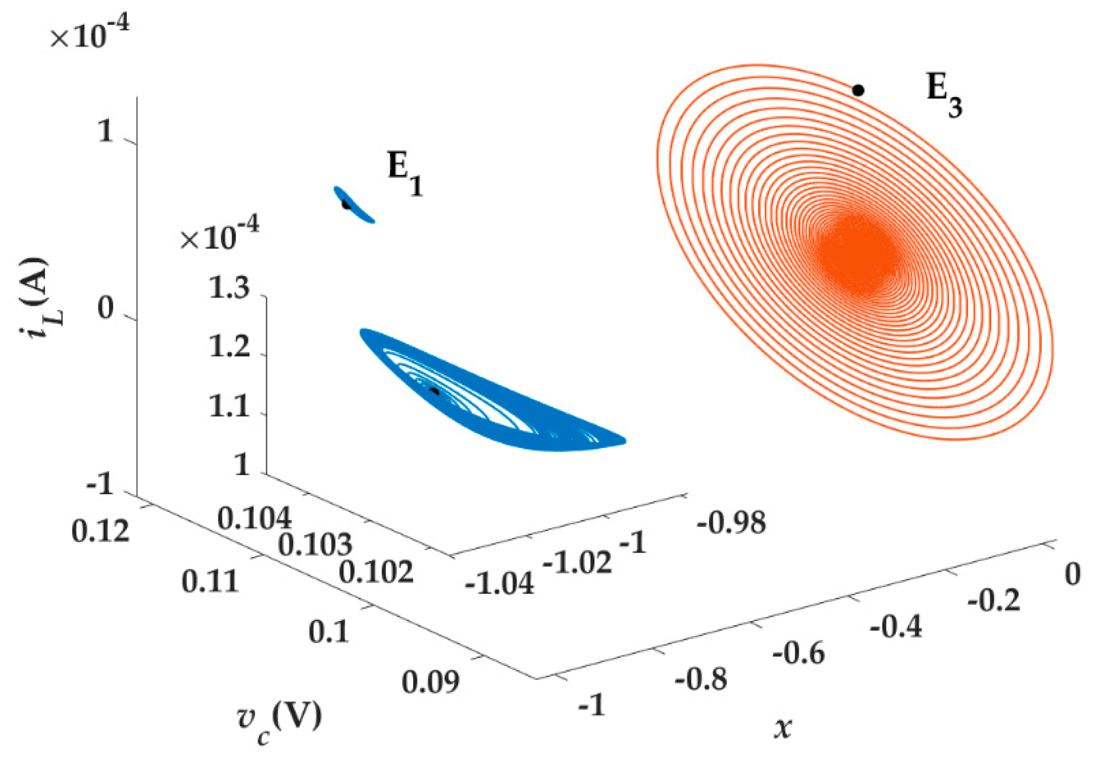
Let dx/dt = 0, dvc/dt = 0, and diL/dt = 0 in Equation (13); the following four equilibrium points of the system can be obtained: E1 (−1.022, 0.1031 V, 0.179 mA), E2 (−0.98, 0.1031 V, 0.109 mA), E3 (0.026, 0.1031 V, 0.104 mA), E4 (0.633, 0.1031 V, 0.516 mA). The four equilibrium points of the system (13) happens to be the equilibrium points of the memristor. Equilibrium E1 is located in the locally active region.
It can be known from the system state equations that the equilibrium points of the system is only related to the internal properties of the memristor and the applied voltage, and has nothing to do with the inductance L and the capacitance C in the circuit. The Jacobian matrix is obtained at an equilibrium point as follows:
J = [ ( g ( x , v ) ) x 1000 × ( 3 + 0.2 x + 0.1 x 2 ) 0 x v C 500 C x 2 + 0.1 1000 C 1 C 0 1 L 0 ]
where
( g ( x , v ) ) x = 1000 × ( ( - 0.05 × ( - 240 x 6 + 3600 x 4 - 3600 x 2 + 240 ) ( 1 + x 2 ) 6 + 0.2 v C + 0.2 v C x )
Table 3 shows the characteristic roots of the Jacobian matrix obtained at the four equilibrium points, in which it has three Saddle focuses (E1, E2, and E4) and one stable focus (E3).
Simulation analysis finds that the circuit has the phenomenon of coexisting attractors, i.e., when the system parameters are fixed, the circuit produces different dynamic characteristics with the different initial values. For example, let the parameters C = 26 μF and L= 0.96 H be fixed; the circuit exhibits a chaotic attractor and a stable equilibrium point under the conditions of initial values E1 and E2, respectively, as shown in Figure 17.

5.2. Influence of Parameters L and C on System Dynamics

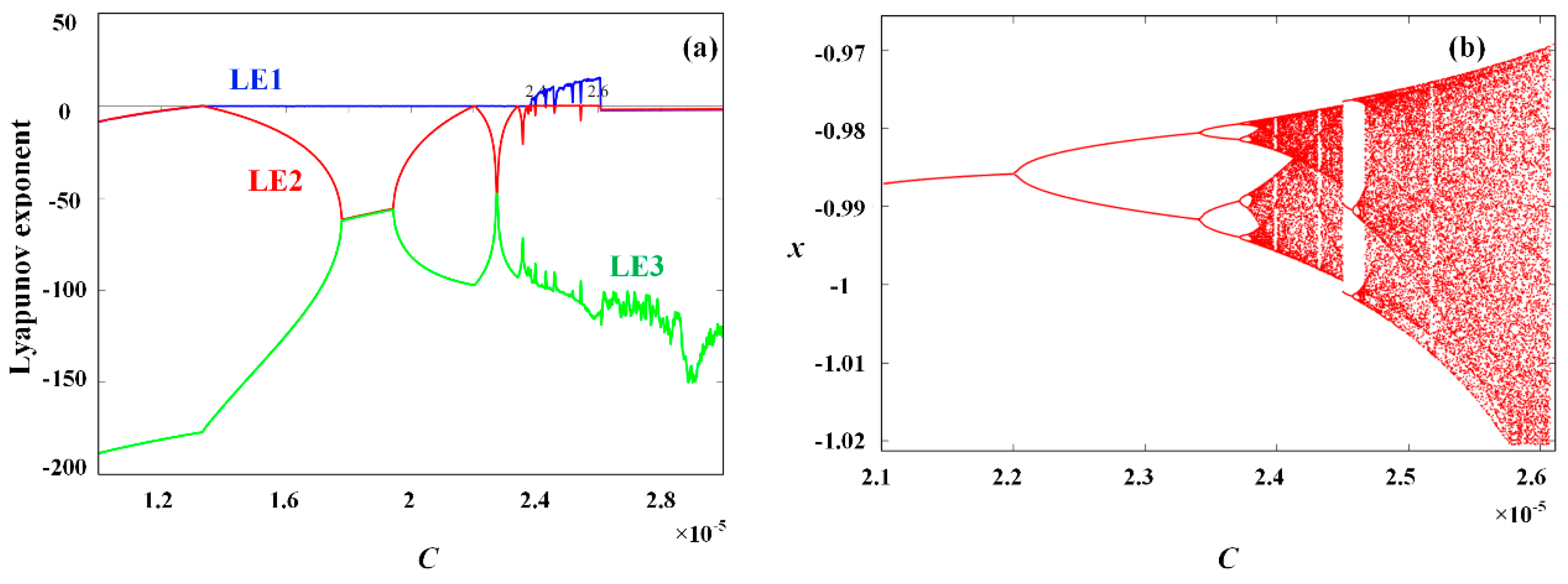
Let us fix the voltage V = 0.1031 V and the initial values E1 (−1.022, 0.1031 V, 0.179 mA); the variation in inductance L and capacitance C can cause the system to bifurcate. Figure 18a shows the variation in the system Lyapunov exponent spectrum [16] with the capacitance C within the interval of 10 μF–30 μF, where inductance L = 0.96 H. Figure 18b shows the bifurcation of the state variable x with the capacitance C within the interval of 21 μF–26.2 μF.
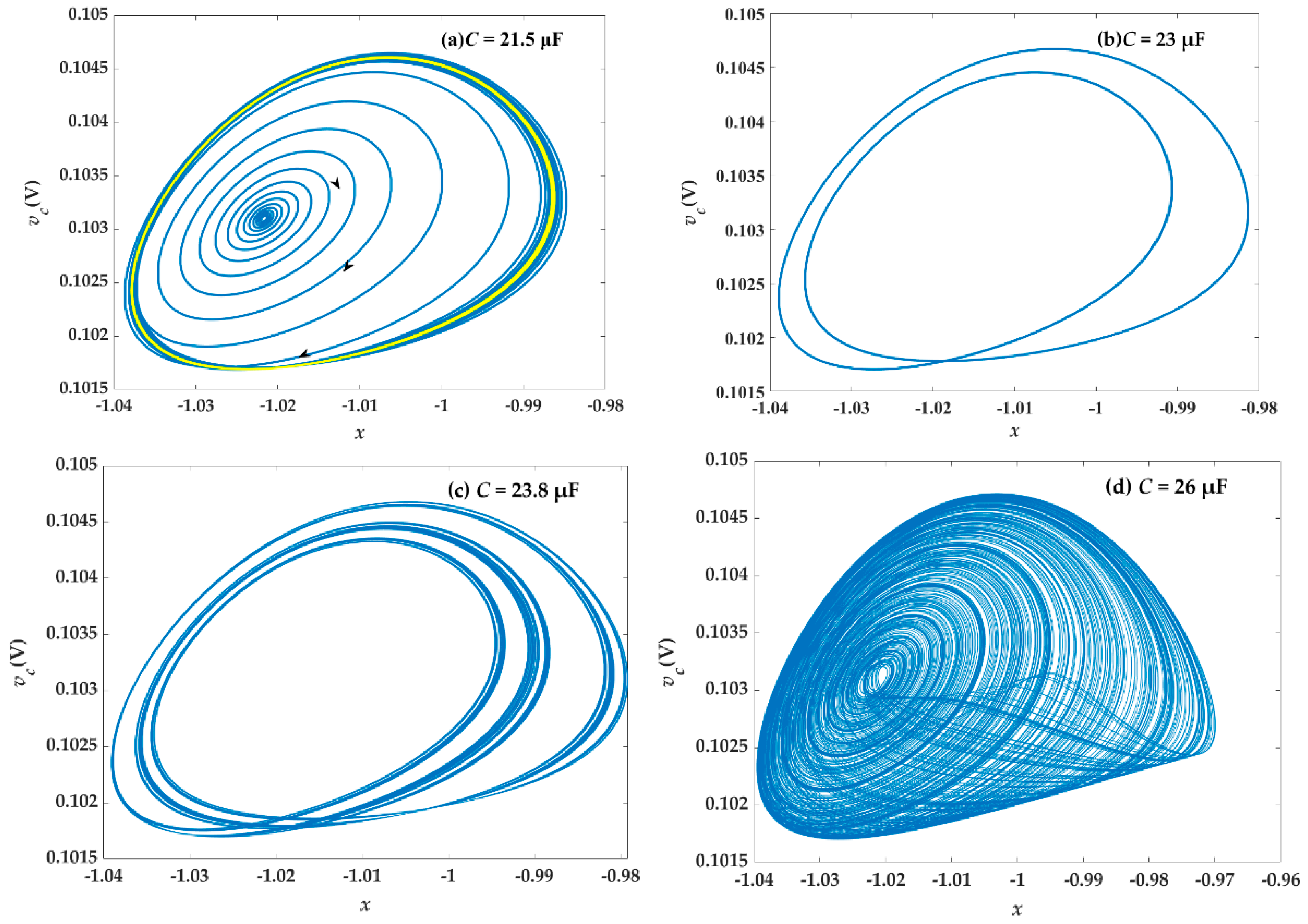
Observe from Figure 18 that as C increases, the system enters into chaotic oscillation through period-doubling bifurcation and finally enters into a stable state rapidly. In this doubling bifurcation process, the system oscillates with two limit cycles of period 1 (yellow cycle in Figure 18a) and period 2 (Figure 19b) when C = 21.5 μF and C = 21.5 μF, respectively; when C > 23.8 μF, the system enters the chaotic region (Figure 19d shows a chaotic attractor with C = 26 μF), where there is a period 3 window, whose corresponding phase diagram is shown in Figure 19c. When the capacitance C ≥ 26.2 μF continues to increase, the system will rapidly stabilize from chaotic oscillation to a stable point attractor.
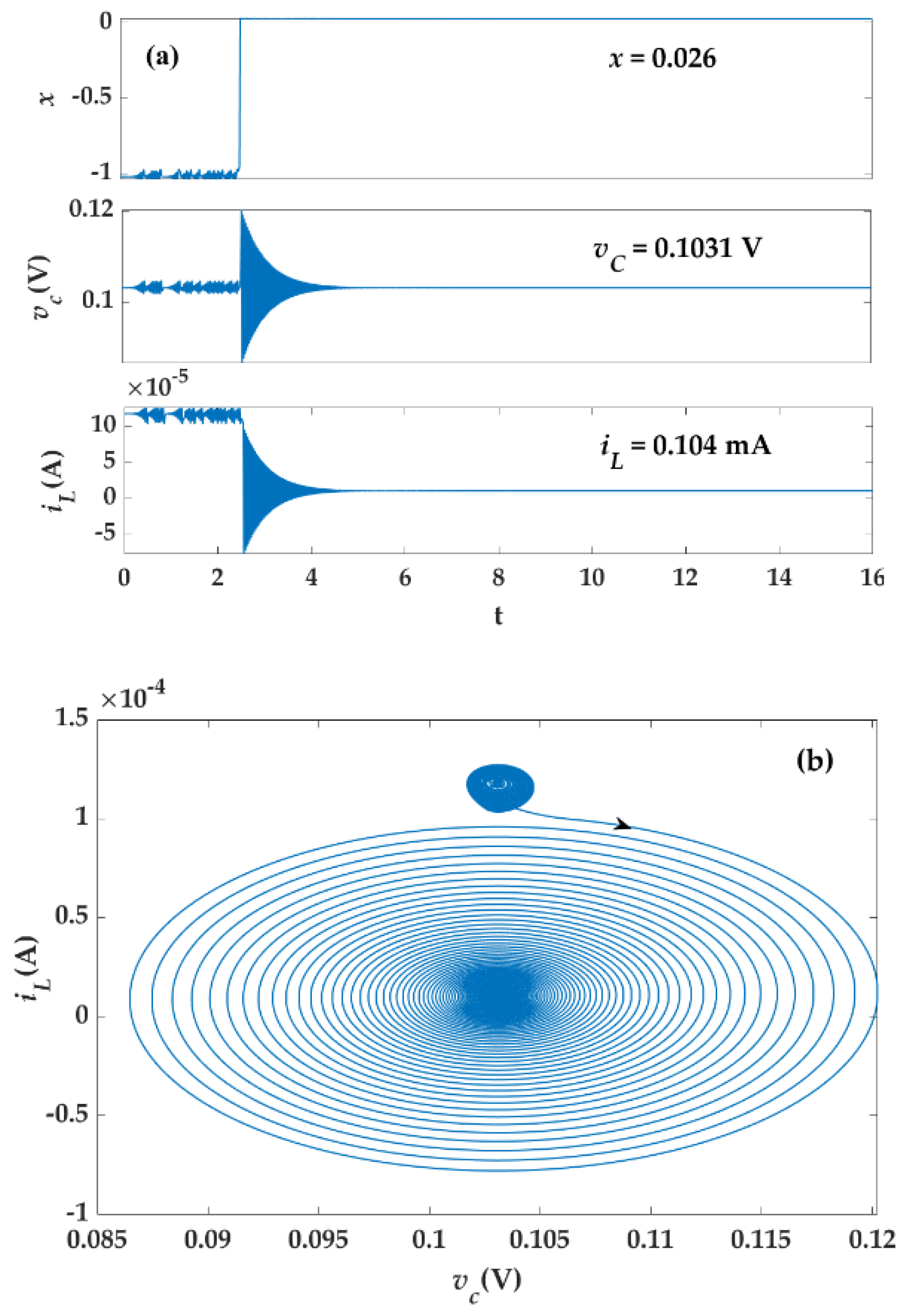
Figure 20 shows the waveforms and attractors of the system as capacitance C = 26.2 μF, where the system gradually stabilizes to E3 (0.026, 0.1031 V, 0.104 mA).
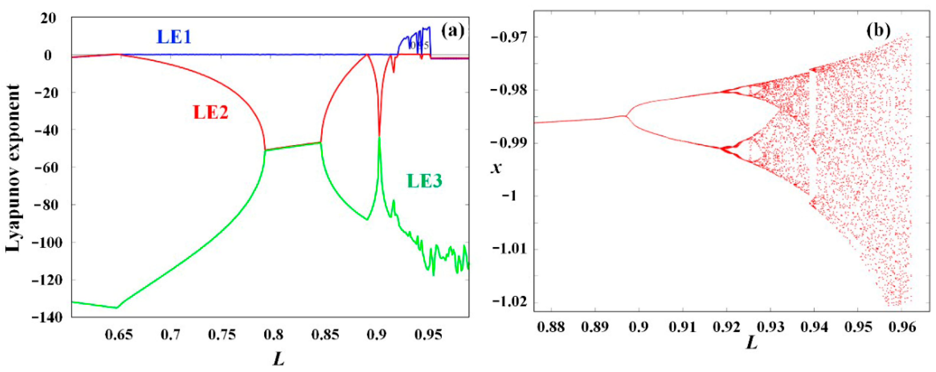
Figure 21 shows the Lyapunov exponent spectrum and the bifurcation of the system with respect to the inductance L, where the applied voltage V = 0.1031 V, the initial value of the memristor is E1 (−1.022, 0.1031 V, 0.179 mA), and the capacitance C = 26 μF. Observe from Figure 21 that for 0.925 H ≤ L ≤ 0.962 H, the system generates chaotic oscillation. With the increase in inductance L, the system bifurcates from period doubling to chaos by period-doubling bifurcation. Obviously, a Period 3 window can be observed from Figure 22b. If L > 0.962 H, the system gradually stabilizes to the system equilibrium point E3.
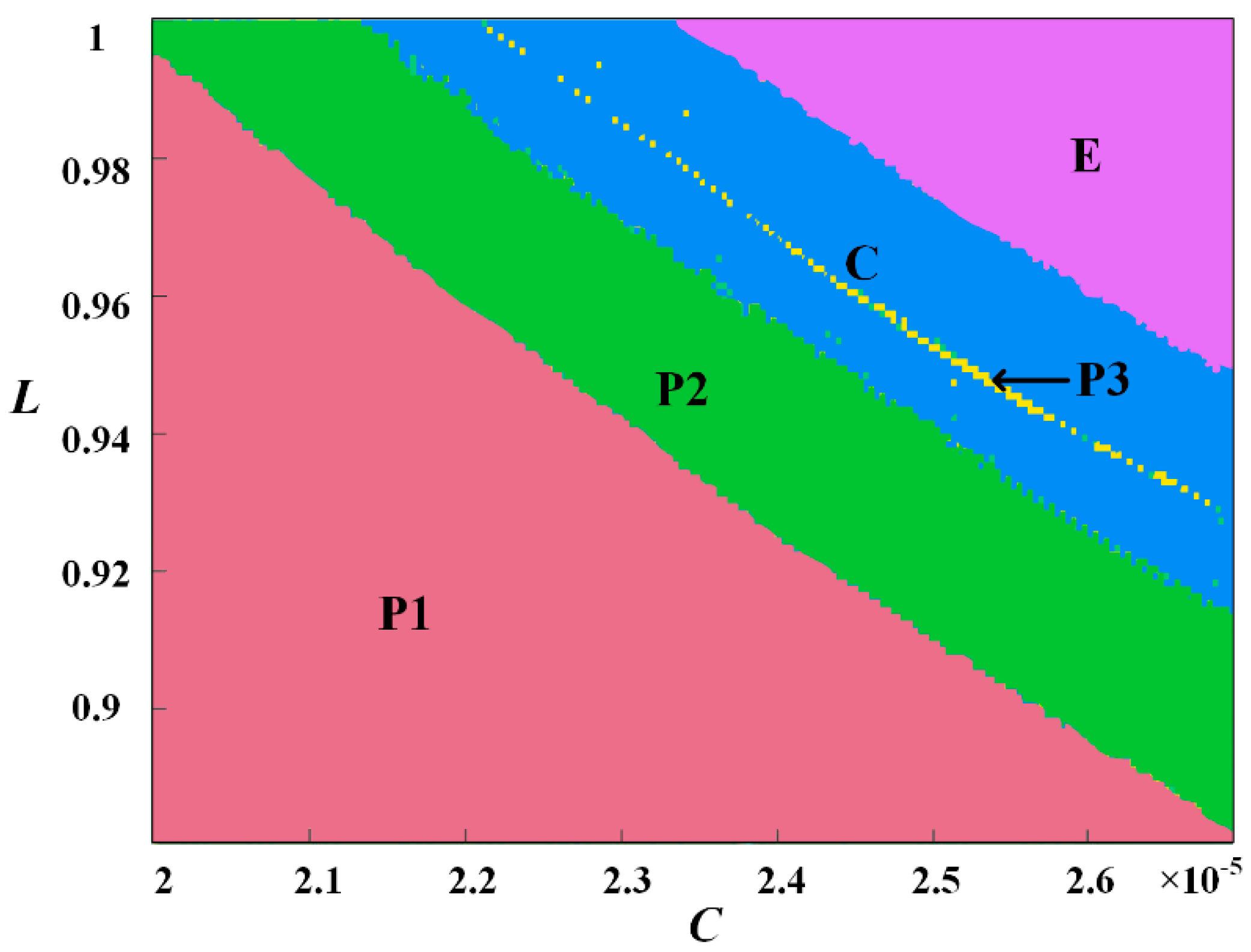
Figure 23 shows the system dynamics map with respect to both inductance L and capacitance C, where the system operating voltage V = 0.1031 V. Obviously, the dynamics map looks like a rainbow pattern, in which the areas labeled P1, P2, P3, C, and E represent period 1, period 2, period 3, chaos, and the stable point, respectively. The typical phase diagrams of those statuses are shown in Figure 24.

6. Conclusions

We design a locally active memristor model whose state function is continuous and derivable within the whole real number interval. Its basic property has been analyzed via the dynamic route map, the pinched vi hysteresis curve, and the DC VI curve. It is found that the memristor is globally passive but locally active and contains two stable locally active regions called the edge of chaos and four unstable locally active regions.
In the stable locally active region, the pole of the admittance function is negative and the zero of the admittance function is positive, while in the unstable locally active region, the pole of admittance function is negative, and the zero of admittance function is positive.
At the two different locally active regions, two kinds of second-order memristive circuits have been built by connecting the memristor in series with a positive inductance L or in parallel with a passive capacitor C. Small-signal analysis and simulations show that the built circuits can generate period oscillation signals.
Adding another passive energy storage component to the second-order circuit, we construct the simplest third-order chaotic circuit, whose equilibrium points and stability are discussed, and the influence of the capacitance and the inductance on system dynamics is further studied. With the change in system parameters, the circuit exhibits various characteristics such as periodic oscillation and chaos, as well as coexisting attractors.

Author Contributions

Conceptualization, F.L., J.L. and G.W.; methodology, F.L., W.Z. and Y.D.; formal analysis, J.L., P.J., J.Y. and G.W.; writing—original draft preparation, F.L., W.Z. and P.J.; writing—review and editing, F.L., Y.D. and J.Y.; supervision, J.L. and G.W.; funding acquisition G.W. All authors have read and agreed to the published version of the manuscript.

Funding

This work was supported in part by the National Natural Science Foundation of China under Grant 62171173, Grant 61771176, and Grant 61801154.

Conflicts of Interest

The authors declare that they have no conflicts of interest.

References

  1. Chua, L. Local activity is the origin of complexity. Int. J. Bifurcat. Chaos 2011, 15, 3435–3456. [Google Scholar] [CrossRef] [Green Version]
  2. Mannan, Z.I.; Choi, H.; Kim, H. Chua corsage memristor oscillator via Hopf bifurcation. Int. J. Bifurcat. Chaos 2016, 26, 1630009. [Google Scholar] [CrossRef]
  3. Dong, Y.; Wang, G.; Chen, G. A Bistable Nonvolatile Locally-active Memristor and its Complex Dynamics. Commun. Nonlinear Sci. Numer. Simul. 2020, 84, 105203. [Google Scholar] [CrossRef]
  4. Mannan, Z.I.; Yang, C.; Kim, H. Oscillation with 4-lobe Chua corsage memristor. IEEE Circuits Syst. Mag. 2018, 18, 14–27. [Google Scholar] [CrossRef]
  5. Mannan, Z.I.; Yang, C.; Adhikari, S.P. Exact Analysis and Physical Realization of the 6-Lobe Chua Corsage Memristor. Complexity 2018, 2018, 8405978. [Google Scholar] [CrossRef]
  6. Jin, P.; Wang, G.; Iu, H.H.C. A Locally-Active Memristor and its Application in Chaotic Circuit. IEEE Trans. Circuits Syst. II Express Briefs 2017, 65, 246–250. [Google Scholar] [CrossRef]
  7. Gu, W.; Wang, G.; Dong, Y.; Ying, J. Nonlinear dynamics in non-volatile locally-active memristor for periodic and chaotic oscillations. Chin. Phys. B 2020, 29, 110503. [Google Scholar] [CrossRef]
  8. Ying, J.; Liang, Y.; Wang, J.; Dong, Y.; Wang, G.; Gu, M. A tristable locally-active memristor and its complex dynamics. Chaos Solitons Fractals 2021, 148, 111038. [Google Scholar] [CrossRef]
  9. Liang, Y.; Wang, G.; Chen, G.; Dong, Y.; Yu, D.; Iu, H.H.C. S-Type Locally active memristor-based periodic and chaotic oscillators. IEEE Trans. Circuits Syst. I Regul. Pap. 2020, 67, 5139–5152. [Google Scholar] [CrossRef]
  10. Ascoli, A.; Slesazeck, S.; Tetzlaff, R.; Maehne, H.; Mikolajick, T. Unfolding the local activity of a memristor. In Proceedings of the 2014 14th International Workshop on Cellular Nanoscale Networks and their Applications (CNNA), Notre Dame, IN, USA, 29–31 July 2014; IEEE: Piscataway, NJ, USA, 2014; pp. 1–2. [Google Scholar]
  11. Chua, L.O. Five non-volatile memristor enigmas solved. Appl. Phys. A Mater. Sci. 2018, 124, 563. [Google Scholar] [CrossRef]
  12. Adhikari, S.P.; Sah Kim, M.P.H.; Chua, L.O. Three fingerprints of memristor. IEEE Trans. Circuits Syst. I Regul. Pap. 2013, 60, 3008–3021. [Google Scholar] [CrossRef]
  13. Chua, L. If it’s pinched it’s a memristor. Semicond. Sci. Technol. 2014, 29, 1–42. [Google Scholar] [CrossRef]
  14. Mannan, Z.I.; Choi, H.; Rajamani, V.; Kim, H.; Chua, L.O. Chua Corsage Memristor: Phase Portraits, Basin of Attraction, and Coexisting Pinched Hysteresis Loops. Int. J. Bifurc. Chaos 2017, 27, 1730011. [Google Scholar] [CrossRef]
  15. Kumar, S.; Strachan, J.P.; Williams, R.S. Chaotic dynamics in nanoscale NbO2 Mott memristors for analogue computing. Nature 2017, 548, 318–321. [Google Scholar] [CrossRef] [PubMed]
  16. Sandri, M. Numerical calculation of Lyapunov exponents. Math. J. 1996, 6, 78–84. [Google Scholar]
Figure 1. Dynamic route map of the memristor.
Electronics 11 01843 g001
Figure 2. Memristor-pinched hysteresis loop.
Electronics 11 01843 g002
Figure 3. DC VI curve of the memristor.
Electronics 11 01843 g003
Figure 4. Small-signal-equivalent circuit of the memristor.
Electronics 11 01843 g004
Figure 5. Zeros and poles of memristor.
Electronics 11 01843 g005
Figure 6. (a) Frequency response and (b) Nyquist diagram of the memristor at V = 0.6 V.
Electronics 11 01843 g006
Figure 7. (a) Small-signal frequency response of memristor and (b) Nyquist diagram of memristor when it operates under V = 0.1031 V, x = −1.022, L* = 1.972 H.
Electronics 11 01843 g007
Figure 8. (a) Parallel capacitance and (b) series resistance of locally active memristor oscillation circuit.
Electronics 11 01843 g008
Figure 9. DC load line is superimposed on the V–I plane.
Electronics 11 01843 g009
Figure 10. Simulation of memristor oscillation circuit: (ac) system initial value V = 0.6000 V and x = 0.3322 and (d) increasing oscillation amplitude, if the initial value is far from the equilibrium point.
Electronics 11 01843 g010
Figure 11. Variation in the real and imaginary parts of the poles of the admittance function in the oscillation circuit with the DC voltage (if C = 97.13 nF).
Electronics 11 01843 g011
Figure 12. Variation in the real and imaginary parts of the poles of the admittance function in the oscillation circuit with the external capacitance (if V = 0.6000 V).
Electronics 11 01843 g012
Figure 13. Variation in the real and imaginary parts of the poles of the admittance function in the oscillation circuit with the external capacitance (if V = 0.1031 V).
Electronics 11 01843 g013
Figure 14. Simulation of memristor oscillation circuit (if V = 0.1031 V and x = −1.022).
Electronics 11 01843 g014
Figure 15. Variation in the real and imaginary parts of the poles of the admittance function in the series inductance oscillation circuit with the DC voltage.
Electronics 11 01843 g015
Figure 16. Chaotic oscillation circuit.
Electronics 11 01843 g016
Figure 17. Two kinds of coexisting attractors of the system with different initial values.
Electronics 11 01843 g017
Figure 18. (a) Lyapunov exponent of the system, and (b) bifurcation of variable x with the capacitance C (if L = 0.96 H).
Electronics 11 01843 g018
Figure 19. Variation in system attractor with capacitance C, where V = 0.1031 V, L = 0.96 H. (a) C = 21.5 μF, (b) C = 23 μF, (c) C = 23.8 μF, (d) C = 26 μF.
Electronics 11 01843 g019
Figure 20. Variation in system attractor (a) waveforms and (b) vc-i phase with C = 26.2 μF.
Electronics 11 01843 g020
Figure 21. (a) Lyapunov exponent spectrum and (b) bifurcation of system with the inductance L (if C = 26 μF).
Electronics 11 01843 g021
Figure 22. Variation in system attractor with inductance L, v = 0.1031 V, C = 26 μF. (a) L = 0.88 H, L = 0.91 H, (b) L = 0.925 H, (c) L = 0.95 H, (d) L = 0.963 H.
Electronics 11 01843 g022aElectronics 11 01843 g022b
Figure 23. Dynamic map with V = 0.1031 V.
Electronics 11 01843 g023
Figure 24. Typical phase diagrams. (a) C = 21.5 μF, L = 0.9 H; (b) C = 24 μF, L = 0.94 H; (c) C = 23.5 μF, L = 0.96 H; (d) C = 24 μF, L = 0.98 H; (e) C = 26 μF, L = 0.98 H.
Electronics 11 01843 g024aElectronics 11 01843 g024b
Table 1. Locally active regions of the memristor.
Range of x LobeCorresponding
Voltage (V)
Corresponding Current I (mA)Stability
(−3.979, −3.667)6(−1.816 × 10⁻⁴, −1.989 × 10⁻⁴)(−2.894 × 10⁻⁶, −2.694 × 10⁻⁶)Unstable
(−1.169, −1.000)2(0.08855, 0.1034)(1.298 × 10⁻⁴, 1.138 × 10⁻⁴)Stable
(−0.3963, −0.2702)3(−0.5395, −0.6600)(−1.387 × 10⁻⁴, −1.140 × 10⁻⁴)Unstable
(0.2649, 0.3909)1(0.6369, 0.5206)(1.084 × 10⁻⁴, 1.316 × 10⁻⁴)Unstable
(0.9921, 1.152)4(−0.09095, −0.07837)(−9.862 × 10⁻⁵, −1.119 × 10⁻⁴)Stable
(3.653, 3.954)5(1.414 × 10⁻⁴, 1.295 × 10⁻⁴)(1.902 × 10⁻⁶, 2.038 × 10⁻⁶)Unstable
Table 2. Properties of locally active regions.
LobeEquivalent Circuit LxPZEnergy Storage Element
1> 0> 0< 0Parallel capacitance
2< 0< 0> 0Series inductance
3> 0> 0< 0Parallel capacitance
4< 0< 0> 0Series inductance
5> 0> 0< 0Parallel capacitance
6> 0> 0< 0Parallel capacitance
Table 3. Characteristic roots of the Jacobian matrix J.
Equilibrium PointCharacteristic ValueEquilibrium Points Types
λ1λ2λ3
E1−157.019.55 + 156.13i9.55–156.13iSaddle focus
E2144.14−45.92 + 159.2i−45.92–159.2iSaddle focus
E3−11810−2 + 204i−2–204iStable focus
E44273.2−8.1 + 204.2i−8.1–204.2iSaddle focus
Publisher’s Note: MDPI stays neutral with regard to jurisdictional claims in published maps and institutional affiliations.