Article

A Wideband High-Gain Dipole with Impedance and Field Control Structures

1
School of Electronic and Information Engineering, South China University of Technology, Guangzhou 510640, China
2
School of Electrical Engineering, Southwest Jiaotong University, Chengdu 611756, China
3
State Key Laboratory of Millimeter Waves, Southeast University, Nanjing 210096, China
*
Author to whom correspondence should be addressed.
Electronics 2022, 11(12), 1892; https://doi.org/10.3390/electronics11121892
Submission received: 21 May 2022 / Revised: 11 June 2022 / Accepted: 13 June 2022 / Published: 16 June 2022
(This article belongs to the Section Microwave and Wireless Communications)

Abstract

:
Dipoles are favorable in various applications because of their simple and light structure. However, narrow bandwidths and low gain values limit their usage in wideband and long-range systems. To solve this problem, this paper presents a new method to achieve wideband high-gain for dipoles with embedded double-sleeve and a bathtub-shaped cavity. The double-sleeve adjusts the dipole’s impedance and enforces wideband matching from 4.8 GHz to 9.4 GHz. Furthermore, the bathtub-shaped cavity reshapes the antenna’s radiation field and elevates the antenna’s boresight gain to be above 10 dBi in the bandwidth of 5 GHz to 9.4 GHz, which is a 7.75 dBi improvement over the 2.15 dBi gain of conventional dipoles. The combination of the two structures creates a wideband high-gain dipole that features an average simulated boresight realized gain of 11.8 dBi in the impedance bandwidth of 64.8%. Thus, the new antenna can work efficiently in wideband and long-range systems because of its enhanced bandwidth and gain performances.

1. Introduction

Wideband antennas with high-gain performance are in great need as they can provide high-speed transmission and long-range communication abilities. Various wideband antennas have been proposed to meet this need. Among these wideband antennas, traveling wave antennas, such as log-periodic antennas [1], horn antennas [2], antipodal tapered-slot antennas [3], and Vivaldi antennas [4], feature high gain values in wide bandwidths. Traveling wave antennas are large and generally radiate in the endfire direction, making them unsuitable for compact and broadside radiation applications. For example, the Vivaldi antenna works from 3.1 GHz to 10.6 GHz with a maximum gain of 5 dBi while its longitude dimension is 0.9 times of the wavelength at 6.75 GHz [5]. Though microstrip antenna radiates in the broadside direction and can achieve high gain values in a wide bandwidth, it may suffer from a complex structure or large size [6].
Dipoles are simple and can radiate in the broadside direction when they are equipped with reflecting plates. Numerous methods have been proposed to increase dipoles’ impedance bandwidths or gain performances to make them suitable for wideband and long-range applications. In [7], a dipole with a reflecting plate achieved a broad bandwidth of 45% and an averaged realized gain of 6.3 dBi. The antennas in [8,9] adopted loading parasitic elements to increase bandwidths. A broadband dipole with a parasitic patch proposed in [8] obtained a 72.7% bandwidth from 1.61 to 3.45 GHz and it’s realized gain ranged from 5.9 dBi to 8.8 dBi. The dipole presented in [9] utilized a parasitic top patch as a director to broaden the impedance bandwidth. In [10], the dipole achieved a wide bandwidth from 1.38 to 3.5 GHz with an average realized gain of 7.2 dBi by using a defected-ground structure. To increase the gain in the bandwidth, several high-gain dipoles have been proposed by adding a reflective plate, frequency selective reflector, or metal cavity. In [11], a high gain dipole with two simple plates proposed worked in the frequency band of 1 GHz to 2.1 GHz, and possessed an average gain of 6 dBi. In [12], the antenna’s boresight gain was increased to 9.8 dBi by installing frequency selective reflectors. The dipole in [13] achieved a stable gain value of around 9 dBi by utilizing a rectangular cavity-shaped reflector. A quadrilateral metal back cavity with an oblique angle was adopted in [14], and the antenna had a small variation gain of about 8 dBi. However, these antennas’ gain values are not high enough or change rapidly in the bandwidth.
This paper presents a new bent dipole with improved bandwidth and elevated in-band boresight stable gain. An embedded matching structure featuring two concentrical sleeves enhances the impedance matching; a bathtub-shaped metal cavity increases the boresight gain by reshaping the dipole’s radiation field at various frequencies. Circuit model and field distribution studies are used to explain the enhancing mechanism, respectively. Simulation results show that the proposed dipole achieves an average realized gain of 11.8 dBi in the frequency band from 4.8 GHz to 9.4 GHz. The proposed antenna’s 3-dB gain bandwidth is 62.9% in the bandwidth from 4.9 GHz to 9.4 GHz, and the impedance bandwidth and gain bandwidth is overlapped.

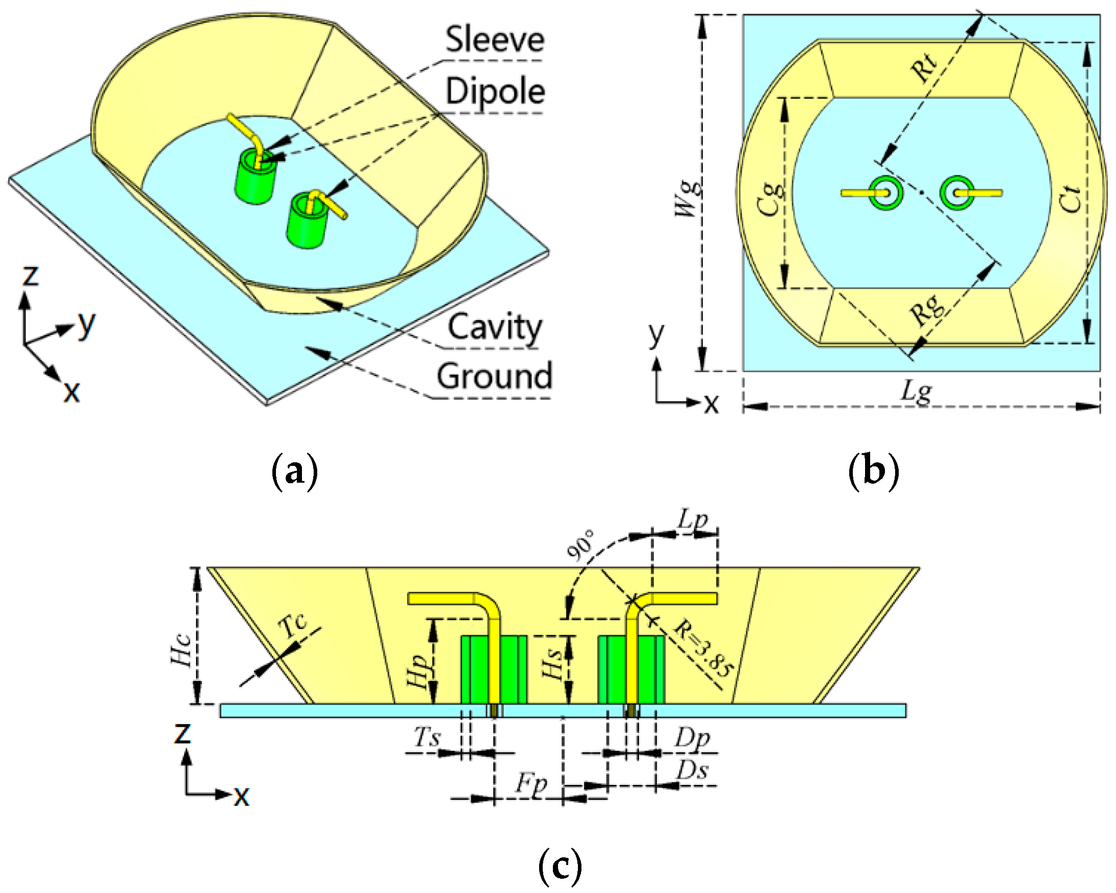
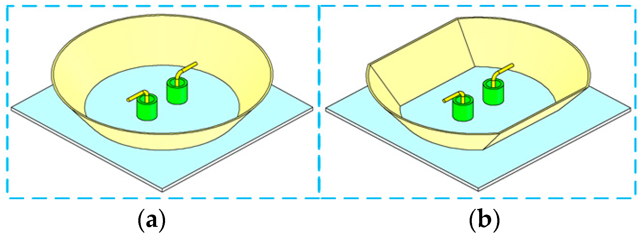
2. Antenna Structure

Figure 1 shows the proposed antenna’s configuration and several dimension variables. The perspective view shown in Figure 1a illustrates that the antenna comprises a bent dipole, two cylindrical sleeves, a bathtub-shaped cavity, and a ground plane. All structures are metal.
The top view of the proposed antenna is depicted in Figure 1b. A rectangular metal plate with the size of Lg × Wg is the antenna’s ground. Two arc plates and two trapezoidal plates comprise a bathtub-shaped cavity. The cavity’s two key dimension variables are the radius Rg and chord length Cg of the arcs at the foot of the cavity. Two other key dimension variables are labeled as the Rt and Ct at the top of the cavity.
Figure 1c illustrates the section-cut view of the antenna. The cylindrical dipole with the same diameter Dp is divided into three sections. The lengths of the vertical and horizontal parts are marked as Lp and Hp, respectively. A quarter arc column with a radius of 3.85 mm connects the horizontal and vertical parts. Two cylindrical sleeves with height Hs, inner diameter Ds, and thickness Ts partially surround the dipole’s vertical sections. Two feeding points’ half distance is Fp. The cavity’s thickness and height are labeled as Tc and Hc, separately. Detailed dimension variable values of the proposed antenna are given in Table 1.

3. Mechanisms of Wideband Impedance Bandwidth and High-Gain

The antenna’s design comprises two parts: achieving wideband impedance matching and getting high boresight gain values in the wideband bandwidth.

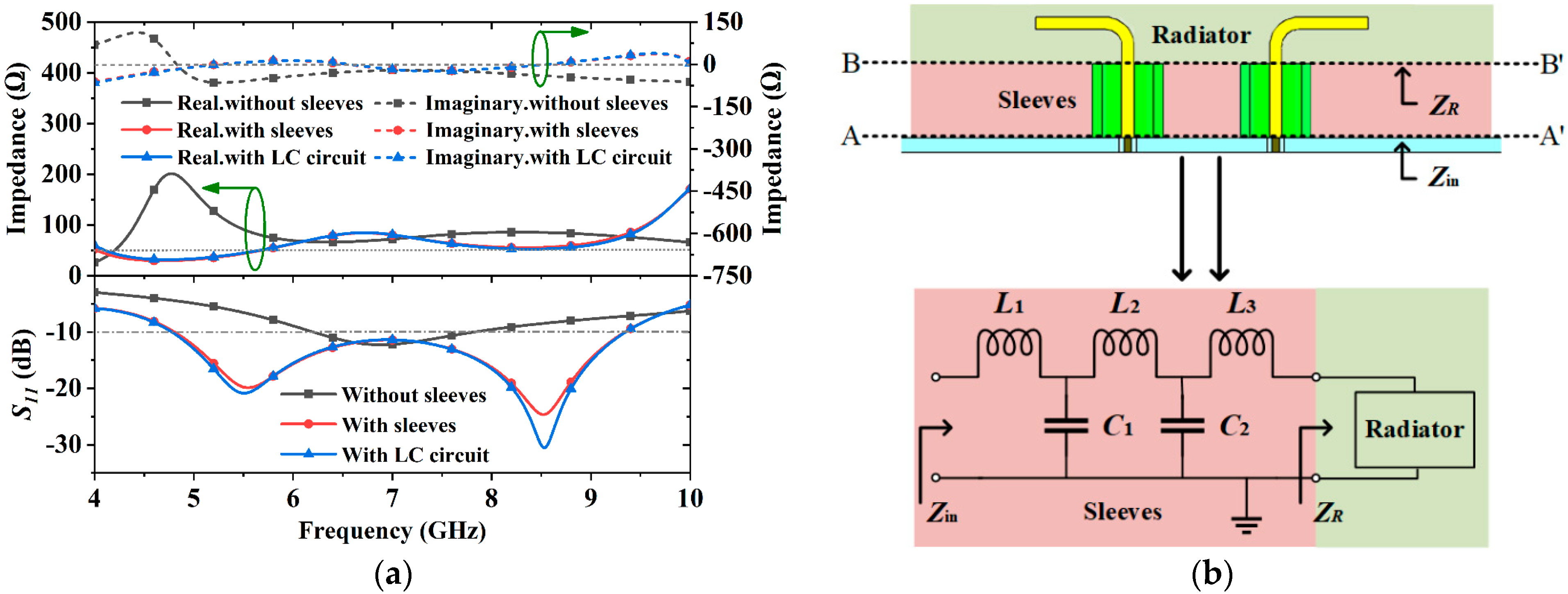
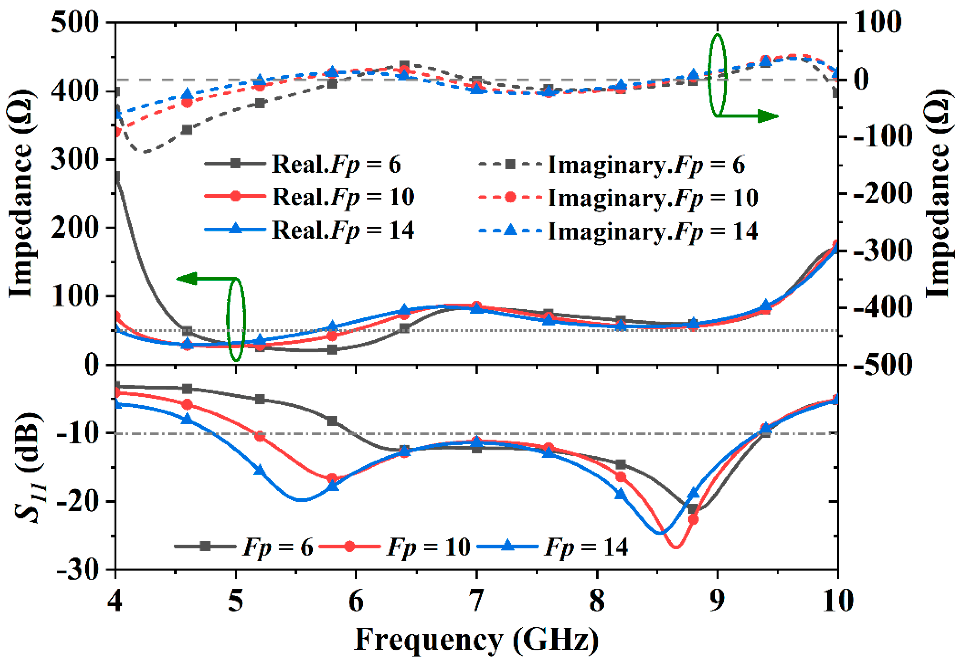
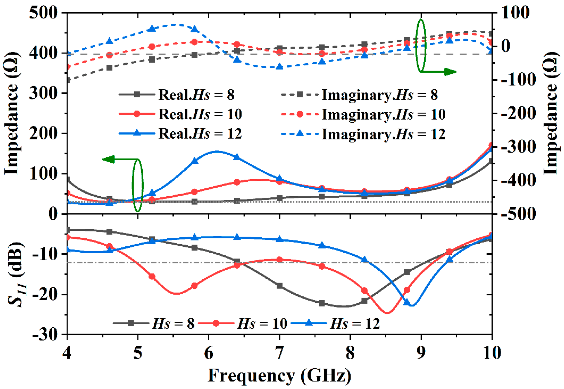
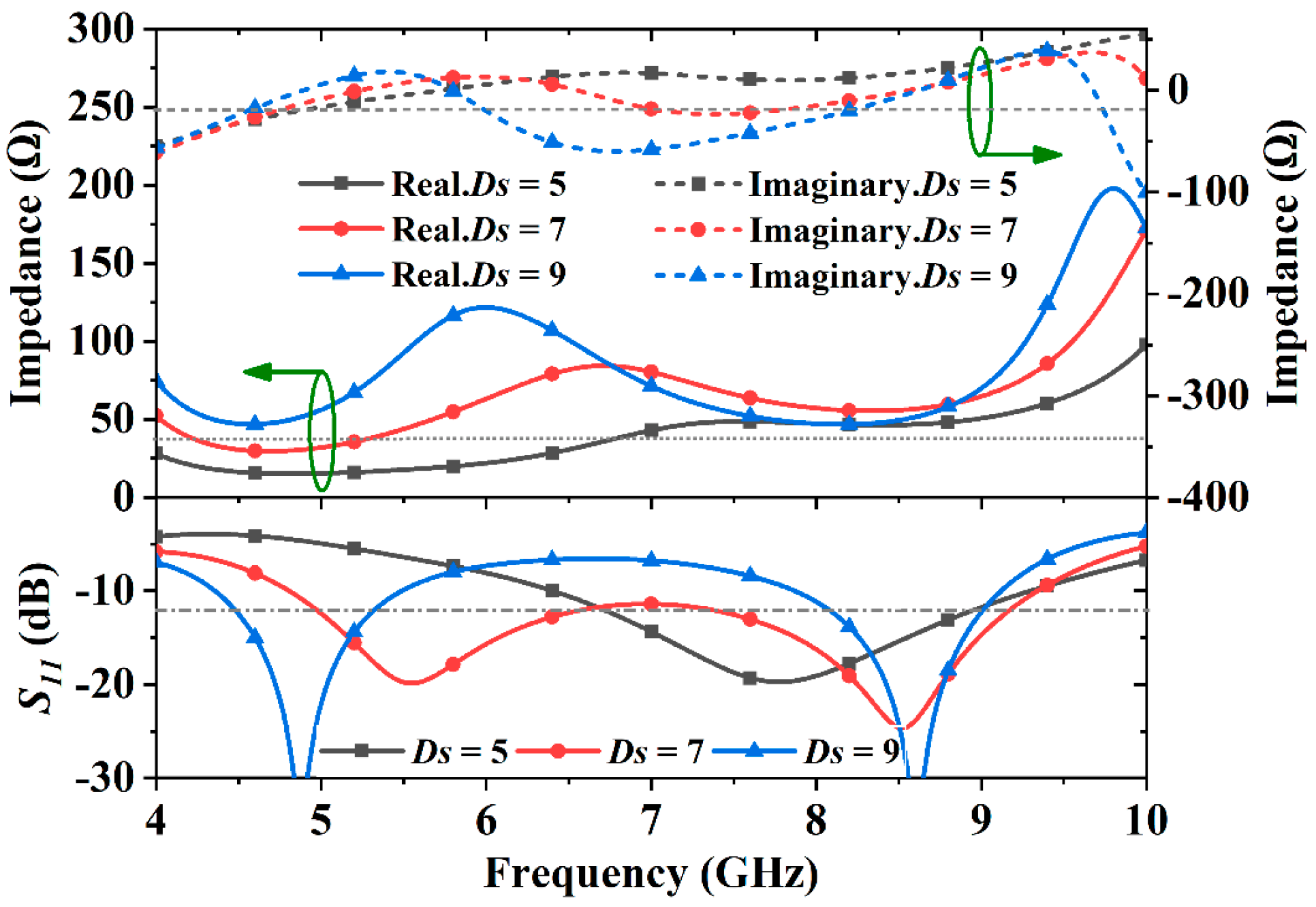
3.1. Wideband Impedance Bandwidth

In the first phase, two identical concentric sleeves encircle the dipole’s vertical parts, as shown in Figure 2, to control the antenna’s impedance. The distances between the two dipoles’ feeds are different because of the sleeves’ presence.
Simulated results indicate that the sleeves can significantly alter the dipole’s impedance to be matched in a wideband. Figure 3a shows that adding the sleeves can significantly reduce the antenna’s real part impedance’s peak value of 200 Ω and get rid of the large variation from +115 Ω to −65 Ω of the imaginary part impedance near 4.8 GHz. Benefiting from the sleeves, the antenna’s real and imaginary part impedance is controlled to be close to 50 Ω and 0 Ω in the frequency band of 4.8 GHz to 9.4 GHz, respectively. Applying the reflection coefficient calculation equation provided in [15]:
S 11 = Z in Z 0 Z in + Z 0  
Small reflection coefficient and good matching are obtained when the antenna’s input impedance is close to the characteristic impedance Z0, which is 50 Ω in this case. The corresponding reflection coefficient curves in Figure 3a verify that applying the sleeves can increase the antenna’s 10-dB impedance bandwidth from 22.8% (6.2–7.8 GHz) to 64.8% (4.8–9.4 GHz).
A simplified equivalent circuit of the sleeves and the dipole is sketched in Figure 3b. The overlapped section of the sleeve and vertical cylinder can be modeled as a fifth-order LC circuit with the extracted impedance values between Zin and ZR, where Zin is the total impedance seen at A - A plane and ZR is the impedance seen at B - B plane. Each sleeve and its corresponding enclosed vertical part of the dipole is equivalent to a section of coaxial cable. The equivalent inductance L and capacitance C in the overlapped section can be found by modifying the coaxial line’s impedance equation [15] to be
L     μ H s 2 π ln D s D p
C     2 π ε H s ln D s / D p
where μ and ε are the dependent permeability and permittivity of the material between the sleeves and the dipole’s vertical parts, respectively, Ds is the inner diameter of the sleeves, Dp is the cylindrical dipole’s diameter, and Hs is the sleeves’ height.
Based on Equations (2) and (3), and the impedance extracted from simulation, the sleeve’s equivalent circuit model is constructed and shown in Figure 3b. The curve fitting method is used to find the values of the inductors and capacitors to be: L1 = 372.22 pH, L2 = 1.75 nH, L3 = 749.27 pH, C1 = 240.26 pF, C2 = 196.13 pF. As plotted in Figure 3a, the results suggest the impedance and S11 curves with LC circuit are identical to those with sleeves.
Simulated results discover that three key dimension parameters, Fp, Hs, and Ds, influence the antenna’s impedance matching most distinctly.
As shown in Figure 4, the results reveal that Fp determines the lower bound of the antenna. When Fp is 6 mm, the antenna’s real part impedance changes from 275 Ω to 20 Ω, and the imaginary part impedance keeps far away from 0 Ω in the frequency band from 4 GHz to 6 GHz. The antenna is matched well, starting from 6 GHz. Increasing Fp to 10 mm, the imaginary part impedance of the antenna varies from −90 Ω to −20 Ω in the frequency band of 4 GHz to 5.1 GHz; the corresponding reflection coefficients are below −10 dB beginning at 5.1 GHz. When Fp is 14 mm, the antenna has a good matched bandwidth from 4.8 GHz to 9.4 GHz, corresponding to a fractional bandwidth of 64.8%.
The impedance tuning effect of the sleeves’ height (Hs) is shown in Figure 5. When Hs = 8 mm, the imaginary part impedance ranges from −55 Ω to −20 Ω from 4.8 GHz to 6.14 GHz. In this case, the fractional bandwidth is 41% (6.14–9.32 GHz). When Hs is 10 mm, the antenna is matched well from 4.8 GHz to 9.4 GHz with a bandwidth of 64.8%. Increasing Hs to 12 mm, the real part of the impedance reaches 155 Ω and the imaginary part of the impedance experiences a large change from +60 Ω to −60 Ω around 6.1 GHz. The corresponding reflection coefficients from 4.8 GHz to 8 GHz are above −10 dB with a decreased bandwidth of 17% (8–9.5 GHz). The results suggest wider bandwidth can be achieved when Hs = 10 mm while all other dimensions are held unchanged.
The impedance controlling effect associated with the sleeves’ inner diameter (Ds) is shown in Figure 6, which demonstrates that an optimal value of Ds yields the widest bandwidth. When Ds is 5 mm, the antenna’s real part impedance is much below 50 Ω from 4.8 GHz to 6.4 GHz, which gives a bandwidth of 37% (6.4–9.3 GHz). When Ds = 7 mm, all the reflection coefficients from 4.8 GHz to 9.35 GHz are smaller than −10 dB with a bandwidth of 64.8%. When Ds is 9 mm, there is a peak value of 120 Ω of the real part impedance at 6 GHz, and the imaginary part impedance is much smaller than 0 Ω in the bandwidth from 5.5 GHz to 7.9 GHz. In this case, the maximum bandwidth is only 23% (4.36–5.5 GHz). These results indicate that broader bandwidth can be obtained around Ds = 7 mm when all other dimensions are unvaried.

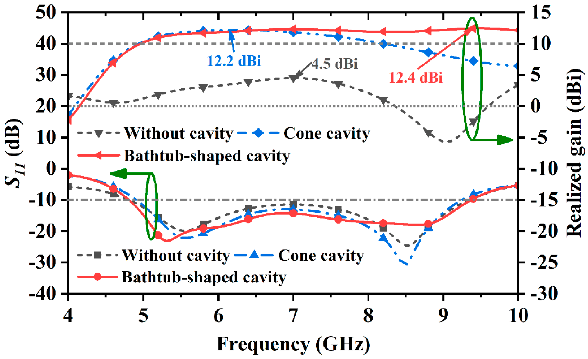
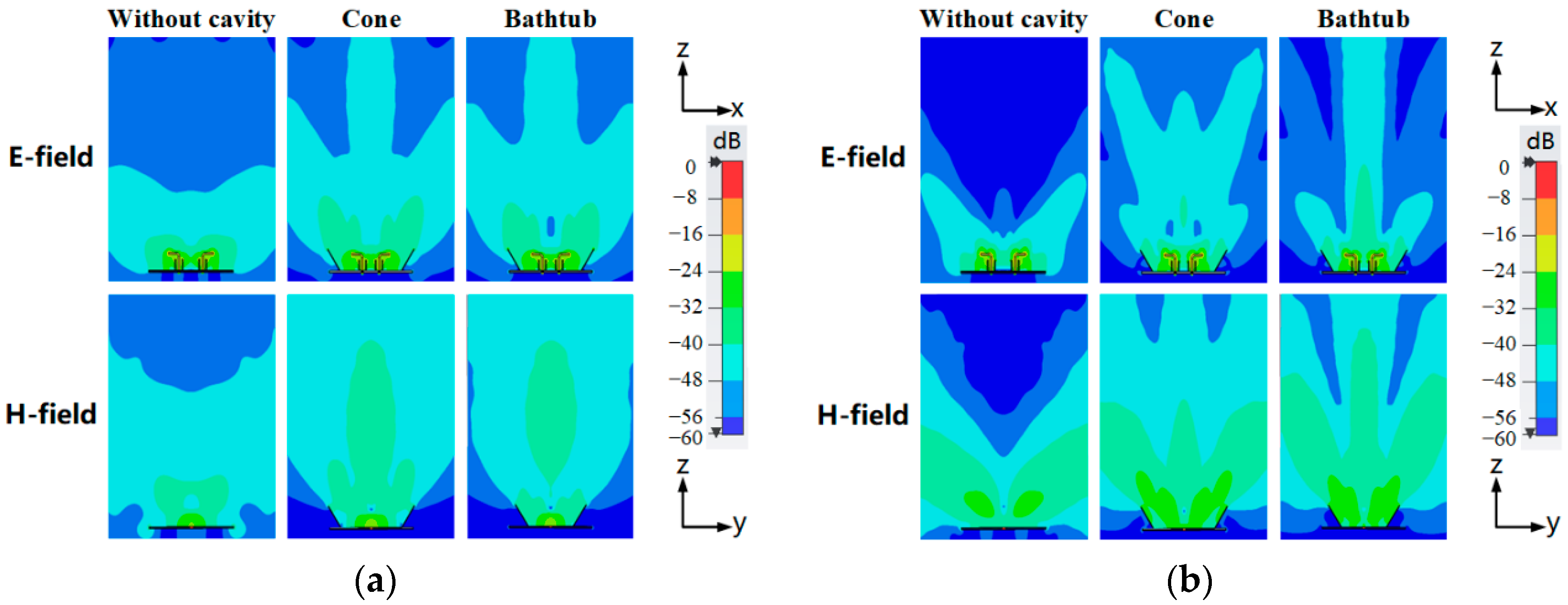
3.2. Stable High Gain in the Bandwidth

In the second design phase, a reflecting cavity is put outside the dipole to elevate the antenna’s boresight gain. Two cavities, as shown in Figure 7, are studied and have been compared to show the bathtub-shaped cavity’s advantage in this design. The cavity’s critical dimension variables have been investigated to reveal their influences on the antenna’s gain performance. When the cavities are applied, the dimension parameter’s value of Fp is adjusted accordingly to keep the antenna working in the bandwidth of 4.8 GHz to 9.4 GHz.
Figure 8 demonstrates that adding the cavity yields higher gain values in a wideband from 4.8 GHz to 9.4 GHz. Both the cone and bathtub-shaped cavities eliminate the sharp gain drop of −5.7 dBi at 9 GHz and increase the maximum realized gain from 4.5 dBi to around 12 dBi. With optimized dimensions, the antennas with the cone cavity or bathtub-shaped cavity can obtain average realized gain values of 10.7 dBi or 11.8 dBi from 4.8 GHz to 9.4 GHz, respectively. In comparison, the dipole without the cavity can only provide a small average gain value of 1.5 dBi in the same frequency band.
The results in Figure 8 indicate that utilizing the bathtub-shaped cavity can obtain higher and stabler gain values than the other. Figure 8 shows the realized gain values of the antenna with the cone cavity decrease from 12 dBi to 7.2 dBi from 7 GHz to 9.4 GHz. By contrast, the realized gain values maintain around 12 dBi from 7 GHz to 9.4 GHz because of using the bathtub-shaped cavity. The bathtub-shaped cavity brings about a wider 3-dB gain bandwidth of 63% (4.9–9.4 GHz) with a higher average realized gain of 11.8 dBi. While the antenna with the cone cavity provides a 3-dB gain bandwidth of 57% (4.8–8.6 GHz) with an average realized gain of 10.7 dBi.
The antenna’s electric and magnetic field distributions have been studied to reveal the cavities’ function. Simulations demonstrate that both cavities reshape the radiation field, which can noticeably improve the antenna’s gain performance. The cavities concentrate the antenna’s main radiation in the boresight direction at various frequencies.
The field distributions at 6 GHz in Figure 9a show that both the electric and magnetic field distributions of the antenna in the boresight direction are weak and the radiation is strong on the two sides of the antenna when there is no cavity. The field is redistributed and the radiation is focused in the boresight direction by employing the cone and bathtub-shaped cavities. Figure 9b further shows that the electric and magnetic field is not distributed in the boresight direction and the antenna nearly does not radiate in the boresight direction when no cavity is applied at 9 GHz. By contrast, the bathtub-shaped cavity significantly focuses the radiation power in the boresight direction. The cone cavity has a similar but weaker redirecting effect compared to the bathtub-shaped cavity. Field distributions at different frequencies indicate that the bathtub-shaped cavity delivers higher and stabler gain values in the antenna’s bandwidth.
The parameter study finds two key dimension parameters, Rg and Hc, affect the antenna’s gain performance most noticeably.
The results in Figure 10 suggest that selecting an optimal value of Rg can obtain higher gain and broader impedance bandwidth simultaneously. When the Rg = 36 mm, the average gain is 12 dBi with a fractional impedance bandwidth of 64.8% from 4.8 GHz to 9.4 GHz. When Rg is 30 mm, the average gain increases from 12 dBi to 13 dBi while the impedance bandwidth decreases to 55% (5.3–9.3 GHz). Increasing Rg to 42 mm, the average gain decreases to 10.7 dBi with a slightly increased impedance bandwidth. A wider impedance bandwidth and higher gain can be found simultaneously when Rg is near 36 mm, with all other dimensions remaining unchanged.
The gain controlling effect of Hc in Figure 11 demonstrates that higher height of the cavity provides higher gain values. When Hc is 20 mm, the average gain is 12 dBi with a fractional impedance bandwidth of 64.8% from 4.8 GHz to 9.4 GHz. Reducing Hc to 15 mm, the average gain drops to 10.7 dBi in the same frequency band. When Hc is 25 mm, the average gain increases to 12.7 dBi. The cavity’s height is chosen to be 20 mm out of size considerations.
Table 2 gives the performance of some wideband high-gain antennas reported in partial references. The simulated results are adopted here for comparison. As we can see, the proposed antenna possesses a 64.8% impedance bandwidth, which is greater than the ones in [7,8,13,14]. The proposed antenna provides a maximum gain of 12.6 dBi and a 3-dB gain bandwidth of 62.9%. Though the antennas’ impedance bandwidths in [12,15] are broader, their maximum gains are below 10 dBi. The proposed antenna possesses high gain values in a wideband, but it does not dominate in terms of size.

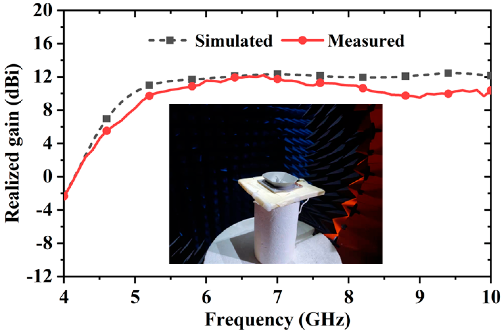
4. Measured Results and Discussions

An ultra-wideband balun [16] using slotline-to-microstrip transition is adopted to feed the antenna. The structure of the balun is shown in Figure 12. Rogers RO4003C laminate (Rogers Corporation, Chandler, AZ, USA) with a thickness of 0.508 mm is used as the balun’s substrate.
The performance of the balun is shown in Figure 13. The S-parameter curves in Figure 13a indicate that the balun works well over the frequency band of 1.8–16 GHz. Figure 13b plots the balun’s amplitude and phase balance performance. The amplitude difference is less than 0.5 dB, and the phase imbalance is 180 ± 1.9° between the two output ports from 1.8 GHz to 16 GHz. The results suggest that the balun can feed the proposed antenna efficiently.
Figure 14 demonstrates the integrated structure of the proposed antenna and the feeding balun. The proposed antenna was fabricated using aluminum alloy material with 3D printing technology. The balun is placed at the bottom of the proposed antenna. The feeds of the dipole are soldered to the balun’s output ports.
Anritsu Vector Network Analyzer (Anritsu, Atsugi, Japan) is used to measure the reflection coefficient of the prototype antenna that is shown in Figure 15. The measured impedance bandwidth is 64.6% (4.78–9.34 GHz) with a reflection coefficient < −10 dB, which shows a good agreement with the simulated one.
The antenna’s radiation performances were measured in the anechoic chamber in our institute. As shown in Figure 16, the measured radiation patterns agree well with the simulation, specifically at 5 GHz, 6 GHz, and 8 GHz, except for the small differences between measurement and simulation about the side-lobes’ amplitude around +/− 30 degrees at 9 GHz. The well-shaped radiation patterns ensure the antenna achieves high gain values in the antenna’s impedance bandwidth, as demonstrated in Figure 17. The gain curves show that the antenna’s gain averages at 10.6 dBi, which is 1.2 dB smaller than the simulation. Our analysis shows that the discrepancy in gain values may result from small fabrication and measurement errors.

5. Conclusions

This paper has presented the simulation results to show that a bent dipole achieves a maximum boresight gain of 12.4 dBi broadside gain and an impedance bandwidth from 4.9 GHz to 9.4 GHz. In the frequency band, the antenna’s boresight gain is 11.8 dBi on average. Results have illustrated that the proposed double-sleeve matching structure and the bathtub reflecting cavity ensure the wideband impedance matching and the high gain performance, respectively. The tested results have verified the antenna’s measured fractional bandwidth is 63% from 4.78 GHz to 9.43 GHz and the measured averaged gain value in the bandwidth is 10.6 dBi. Because the proposed antenna possesses high gain values in a wide frequency band with a relatively simple structure, it is suitable for various wideband and long-range wireless applications.

Author Contributions

Conceptualization, H.Z. (Honglin Zhang); methodology, H.Z. (Honglin Zhang); validation, H.Z. (Haiquan Zhong) and J.Y.; formal analysis, H.Z. (Haiquan Zhong), J.Y. and H.Z. (Honglin Zhang); investigation, H.Z. (Haiquan Zhong); writing—original draft preparation, H.Z. (Haiquan Zhong) and H.Z. (Honglin Zhang); writing—review and editing, H.Z. (Honglin Zhang), S.L. and B.L. All authors have read and agreed to the published version of the manuscript.

Funding

This research was funded by the National Natural Science Foundation of China under grant No. 62071182.

Conflicts of Interest

The authors declare no conflict of interest.

References

  1. Liu, G.; Li, H.; Chen, Y.; He, H.; Gao, S.; Yang, S. A Wideband, Low-Profile Log-Periodic Monopole Array with End-Fire Scanning Beams. IEEE Antennas Wirel. Propag. Lett. 2018, 17, 2414–2418. [Google Scholar] [CrossRef]
  2. Liu, K.; Ge, Y.; Lin, C. A compact wideband high-gain metasurface-lens-corrected conical horn antenna. IEEE Antennas Wirel. Propag. Lett. 2019, 18, 457–461. [Google Scholar] [CrossRef]
  3. Siddiqui, J.Y.; Saha, C.; Sarkar, C.; Shaik, L.A.; Antar, Y.M.M. Ultra-Wideband Antipodal Tapered Slot Antenna with Integrated Frequency-Notch Characteristics. IEEE Trans. Antennas Propag. 2018, 66, 1534–1539. [Google Scholar] [CrossRef]
  4. Lee, D.H.; Yang, H.Y.; Cho, Y.K. Tapered slot antenna with band-notched function for ultrawideband radios. IEEE Antennas Wirel. Propag. Lett. 2012, 11, 682–685. [Google Scholar]
  5. Hood, A.Z.; Karacolak, T.; Topsakal, E. A small antipodal vivaldi antenna for ultrawide-band applications. IEEE Antennas Wirel. Propag. Lett. 2008, 7, 656–660. [Google Scholar] [CrossRef]
  6. Lee, K.F.; Tong, K.F. Microstrip patch antennasbasic characteristics and some recent advances. Proc. IEEE 2012, 100, 2169–2180. [Google Scholar]
  7. Li, Y.; Luk, K.M. A linearly polarized magnetoelectric dipole with wide H-plane beamwidth. IEEE Trans. Antennas Propag. 2014, 62, 1830–1836. [Google Scholar] [CrossRef]
  8. Chang, L.; Chen, L.L.; Zhang, J.Q.; Li, D. A Broadband Dipole Antenna with Parasitic Patch Loading. IEEE Trans. Antennas Propag. 2018, 17, 1717–1721. [Google Scholar] [CrossRef]
  9. Xie, C.; Yin, J.; Li, X.; Pang, F.; Liu, Q.; Yang, J. An Ultrawideband Dipole with a Director as a Feed for Reflector Antennas. IEEE Trans. Antennas Propag. 2017, 16, 1341–1344. [Google Scholar] [CrossRef] [Green Version]
  10. Zeng, J.; Luk, K.M. A Simple Wideband Magneto-Electric Dipole Antenna. In Proceedings of the 2018 International Symposium on Antennas and Propagation (ISAP), Busan, Korea, 23–26 October 2018; Volume 17, pp. 1497–1500. [Google Scholar]
  11. Zhou, S.G.; Li, J.Y. Low-profile and wideband antenna. IEEE Antennas Wirel. Propag. Lett. 2011, 10, 373–376. [Google Scholar] [CrossRef]
  12. Kim, D.; Kim, E. A high-gain wideband antenna with frequency selective side reflectors operating in an anti-resonant mode. IEEE Antennas Wirel. Propag. Lett. 2015, 14, 442–445. [Google Scholar] [CrossRef]
  13. Ge, L.; Gao, S.; Zhang, D.; Li, M. Magnetoelectric dipole antenna with low profile. IEEE Antennas Wirel. Propag. Lett. 2018, 17, 1760–1763. [Google Scholar] [CrossRef]
  14. Tao, J.; Feng, Q.; Vandenbosch, G.A.; Volskiy, V. Director-Loaded Magneto-Electric Dipole Antenna with Wideband Flat Gain. IEEE Trans. Antennas Propag. 2019, 67, 6761–6769. [Google Scholar] [CrossRef]
  15. Ludwing, R.; Bretchko, P. RF Circuit Design: Theory and Applications; Prentice Hall: Upper Saddle River, NJ, USA, 2000. [Google Scholar]
  16. Horestani, A.K.; Shaterian, Z. Ultra-wideband balun and power divider using coplanar waveguide to microstrip transitions. AEU—Int. J. Electron. Commun. 2018, 95, 297–303. [Google Scholar] [CrossRef]
Figure 1. Configuration of the proposed antenna. (a) perspective view; (b) top view; (c) section-cut view.
Electronics 11 01892 g001
Figure 2. The proposed antenna’s wideband design procedure. (a) dipole without sleeves; (b) dipole with sleeves.
Electronics 11 01892 g002
Figure 3. (a) Impedance and S11 when the antenna has the double-sleeve or not. (b) Equivalent circuit model of the antenna.
Electronics 11 01892 g003
Figure 4. The impedance and S11 for different values of Fp.
Electronics 11 01892 g004
Figure 5. The impedance and S11 for different values of Hs.
Electronics 11 01892 g005
Figure 6. The impedance and S11 for different values of Ds.
Electronics 11 01892 g006
Figure 7. The proposed antenna’s high-gain design procedure. (a) antenna with a cone cavity; (b) antenna with a bathtub-shaped cavity.
Electronics 11 01892 g007
Figure 8. The S11 and boresight realized gains of the antennas.
Electronics 11 01892 g008
Figure 9. Uniform electric and magnetic field distribution of the antennas at different frequencies. (a) 6 GHz. (b) 9 GHz.
Electronics 11 01892 g009
Figure 10. The S11 and boresight gains for different values of Rg.
Electronics 11 01892 g010
Figure 11. The S11 and boresight gains for different values of Hc.
Electronics 11 01892 g011
Figure 12. Layout of the ultra-wideband balun.
Electronics 11 01892 g012
Figure 13. (a) Simulated S-parameters of the ultra-wideband feeding balun. (b) Simulated amplitude imbalance and phase imbalance at two out ports of the ultra-wideband balun.
Electronics 11 01892 g013
Figure 14. Integrated structure of the proposed antenna and the ultra-wideband balun. (a) top view; (b) bottom view.
Electronics 11 01892 g014
Figure 15. Simulated and measured return loss of the proposed antenna.
Electronics 11 01892 g015
Figure 16. Simulated and measured radiation patterns of the proposed antenna at different frequencies on the E-plane.
Electronics 11 01892 g016aElectronics 11 01892 g016b
Figure 17. Simulated and measured realized gains of the proposed antenna.
Electronics 11 01892 g017
Table 1. Dimension value (mm) of the proposed antenna.
ParameterLgWgLpHpDpFpDsHs
Value1001009.512.51.710710
ParameterTsTcRgCgRtCtHc
Value1.313653.55184.320
Table 2. Performance comparison between proposed and reported wideband high-gain antennas.
Ref.Dimensions
L3)
Impedance BW
(GHz) (BW%)
Maximum
Gain (dBi)
3-dB Gain BW
(GHz) (BW%)
GBW/IBW
[7]0.8 × 0.8 × 0.252.4–3.8 (45.4%)6.72.4–3.8 (45.4%)1
[8]0.8 × 0.8 × 0.241.6–3.5 (45.4%)91.6–3.1 (63.3%)0.87
[12]0.66 × 0.43 × 0.11–2.1 (80%)9.31.5–2.1 (60%)0.75
[13]1.7 × 1.4 × 0.281.7–2.6 (41.5%)121.7–2.3 (32.9%)0.79
[14]0.66 × 0.43 × 0.11.8–2.8 (43.6%)10.81.9–2.8 (39%)0.89
[15]0.6 × 0.6 × 0.261.6–3.8 (81.5%)8.21.6–3.8 (81.5%)1
This work1.7 × 1.5 × 0.324.8–9.4 (64.8%)12.64.9–9.4 (62.9%)0.97
L is the waveguide wavelength at the starting frequency in the operational BW. IBW is the S11-10 dB impedance bandwidth. GBW is the 3-dB gain bandwidth. According to [15], a new parameter GBW/IBW is defined to indicate the coincidence between the 3-dB gain bandwidth and the S11-10 dB impedance bandwidth).
Publisher’s Note: MDPI stays neutral with regard to jurisdictional claims in published maps and institutional affiliations.

