Abstract
This paper proposes a small antenna system (47 mm × 8 mm × 0.2 mm) to be used in a medical mask. The medical mask is composed of a frame and shield. The frame is made of polycarbonate (PC), and the shield is made of polyethylene terephthalate (PET). The author sets two groups of antennas on the upper side of the frame and sets two other groups of antennas on the sides facing away from the face of the shield. The substrates of the four antennas are all FR4 (εr = 4.4, tanδ = 0.02), so the first antenna type is a combination of PC and FR4, and the second antenna type is a combination of PET and FR4. The antenna system has three working frequency bands, in which the reflection coefficient is lower than −10 dB after actual measurement, and its working frequency bandwidth is 2.38–2.62 GHz, 3.38–3.74 GHz, and 5.14–8 GHz, respectively. It can be effectively used in 5G FR1 and Wi-Fi 7 frequency bands and can easily be combined with medical masks of different materials. This antenna system can use Wi-Fi 7 for wireless transmission indoors and use the 5G FR1 frequency band for wireless transmission outdoors, achieving seamless transmission capabilities.
1. Introduction
The most common topic discussed in the fourth industrial revolution is the Internet of Things, and among the important items in the Internet of Things are wearable devices [1]. Various wearable devices have different functions according to the needs of different industries such as changing the way of work in various industries, improving people’s work efficiency, or generating new ways of working [2]. From the recent research literature on the development of wearable devices, in the next few years, wearable devices will also bring astonishing industrial value; there will also be more and more different applications [3], such as smart wristbands, smart rings, smart clothes, smart pants, etc. To cooperate with ergonomics to achieve the best fit, or to measure the vital signs on the body surface, wearable devices must be attached to the torso, arms, legs, head, etc., so that part of the shape will be curved in order to achieve the best fit [4]. In recent years, another topic that has attracted attention is the metaverse [5], and wearable devices are also related to the metaverse. The most relevant wearable devices are virtual reality devices, augmented reality devices, and mixed reality devices. Wearable devices such as head-mounted [5] and curved-display [6] are usually installed in the head-mounted video device, and their appearance is also curved. So that the internal electronic components can be arranged and installed, it is necessary to cooperate with such a curved surface.
In addition, the sudden outbreak of the epidemic in the past two years has disrupted people’s daily lives and has also drawn attention to the application of wearable devices in public health and medical fields [7,8,9]. For example, medical personnel need to wear various medical protective equipment, including medical protective masks, masks, protective clothing, and gloves. This medical protective equipment can be transformed into wearable devices by adding electronic equipment [3,4]. One of the important items is to join a wireless communication system [10,11]. This allows medical personnel to transmit various medical data to the remote end quickly and in real time through wearable devices, allows patients to use wearable devices to transmit medical information or monitor physiological information in real time, and allows the tracking of patients via wearable devices [8]. For the above reasons, one of the most important items of wearable devices is to connect to the internet.
However, most antenna designs of current wearable devices have the following problems:
- The wearable devices only use Wi-Fi for data transmission [12,13,14,15,16], or only use 4G/5G frequency bands for data transmission [17]. However, the wearable device users not only use the wearable device indoors but may also move outdoors;
- A small number of wearable devices are designed with antennas that include Wi-Fi and 5G communication frequency bands [18] or use Wi-Fi and LTE frequency bands for data transmission [19,20]; other antennas are even designed with three different frequency bands [21]. However, the design of the antenna is too complicated and the area is too large so that the antenna is not suitable to be installed in the wearable device;
- Most of the antennas are flat designs [13,14,15,16,17,18,19,20,21], which cannot be applied to wearable devices with curved-structure designs;
- Traditional antenna designs are only applied to a single material [12,13,14,15,16,17,18,19,20,21], while wearable devices are often made of multiple materials.
Therefore, for the antenna system design of current wearable devices, it needs to have the following characteristics:
- For indoor and outdoor use at the same time. A variety of antennas are required to support different frequency bands to achieve a high broadband transmission rate and good transmission path reliability;
- Under the premise of meeting the aforementioned characteristics, the size of the antenna needs to be further miniaturized;
- Design the antenna system on the flat and curved positions of the wearable device;
- The antenna system needs to have good robustness, so that it can be used on different composite materials or placed on a flat or curved surface, without much design difference.
In summary, this paper designs an antenna system for medical masks. The medical mask includes a frame made of PC material and a shield made of PET material. The frame and the shield are assembled with an antenna made of FR4 material as a substrate. The FR4-substrate design is a set of antennas on the plane position of the frame. Another set of antennas located on the curved surface of the shield. The design of the two sets of antennas is similar. The operating frequency bands are 5G FR1 and Wi-Fi7’s Multiple-Input Multiple-Output (MIMO) antenna system. It can provide the transmission of large amounts of data indoors and outdoors, fully meeting the above design requirements. Furthermore, in the Section 2 of this paper, the antenna design and simulation results are introduced, the Section 3 is the actual measurement results of the antenna system of the medical mask in free space, and the Section 4 contains the simulation and measurement results of the medical mask–antenna system worn on the head. A comparison table with other references is created. The paper ends in the Section 5.
2. Antenna Design
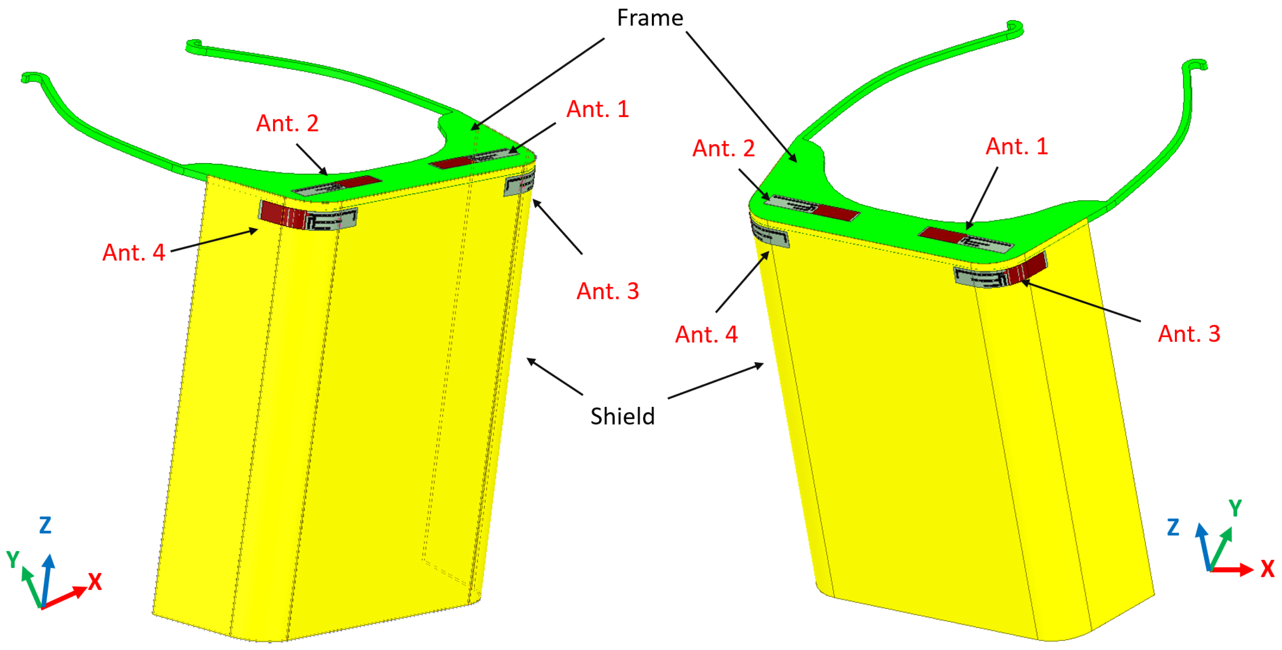
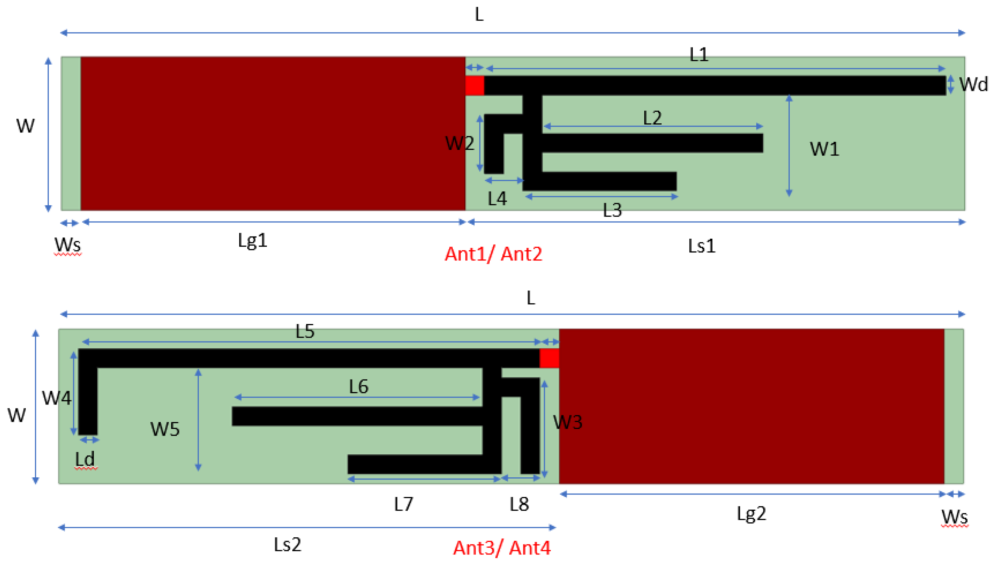
Most of the antenna designs in the literature are simple and common single-stage antennas [12,16,18,19,21]. One of these antennas is designed as a multi-frequency antenna [18,21], but these antennas are not MIMO antenna systems. The size of the antenna system is too large, and there are further possibilities for miniaturization. In addition, all references to antennas are designed on a single material. This paper proposes a 4 × 4 MIMO antenna system for 5G FR1 and Wi-Fi 7 frequency bands. This antenna system is applied to a medical mask, which consists of a frame and a shield. The frame is made of PC (εr = 2.31 tanδ = 0.001). The front edge and the narrowest part in the center of the frame without the tripod are both approximately 120 mm × 25 mm, and the thickness is 1.5 mm. The material of the shield is PET (εr = 3.7 tanδ = 0.018), the size is 235 mm × 190 mm, and the thickness is 0.188 mm. The antenna system is designed on the FR4 substrate, the thickness of the substrate is 0.2 mm (εr = 4.4, tanδ = 0.02), and the overall size of the substrate is 47 mm × 8 mm × 0.2 mm. The geometric structure of the medical mask and the antenna system is shown in Figure 1. Among them, two sets of antennas (Ant. 1 and Ant. 2) with the same geometric shape are designed in the frame to form the first antenna type, and another two sets of antennas (Ant. 3 and Ant. 4) are set on the shield to form the second antenna type. The geometry of the first antenna type is similar to that of the second antenna type. In other words, the substrate of the first antenna type is a combination of PC and FR4, and the substrate of the second antenna type is a combination of PET and FR4. Furthermore, the second antenna type is placed on the curved position of the shield. Finally, the antenna system is mainly composed of a monopole antenna and a metal ground plane disposed on the same surface printed on an FR4 substrate.
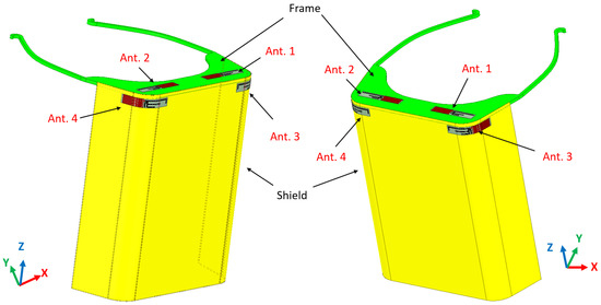
Figure 1.
Schematic of the antenna system on a medical mask.
2.1. Antenna Evolution
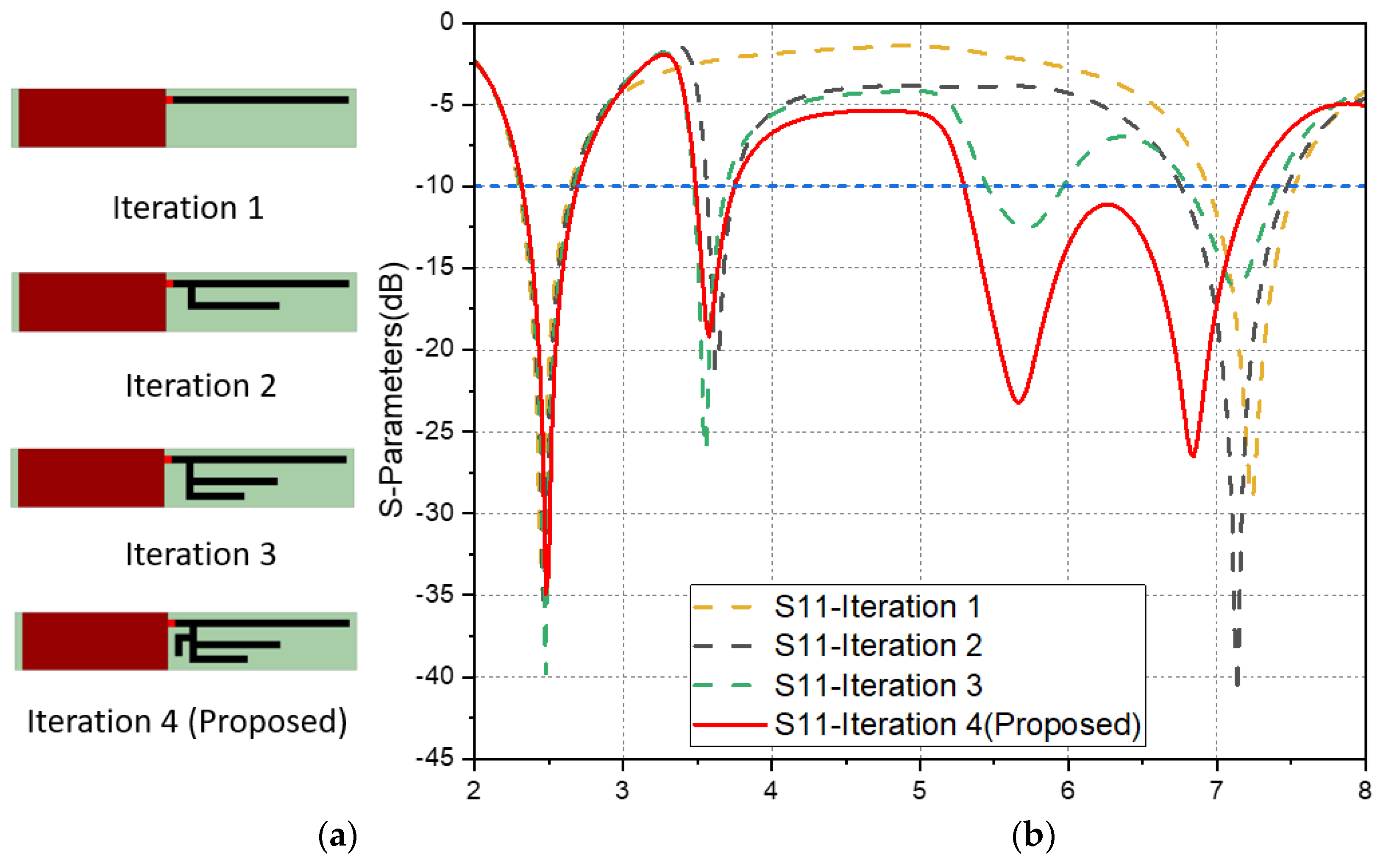
Antenna 1 (Ant. 1) of the first antenna type has the same geometric shape as antenna 2 (Ant. 2) and is placed in the symmetrical position of the frame. The evolution process of Ant. 1 will be described below. The evolution steps and reflection coefficients are shown in Figure 2. In the design process, it is necessary to consider that Ant. 1 printed on the FR4 substrate needs to be installed on frames of different materials. Therefore, we draw a three-dimensional model according to the size of the frame and the shield, import the three-dimensional model into the commercial software High-Frequency Structure Simulator 2021 R1 version (HFSS) for simulation analysis, and attach the FR4 substrate to the symmetrical position of the frame for simulation design.
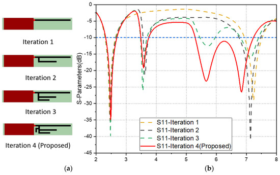
Figure 2.
(a) Evolution steps of Ant. 1, (b) corresponding reflection coefficients (|S11|).
As shown in Figure 2, in terms of Ant. 1, in iteration 1, we first design an 8 mm × 20 mm metal ground plane on the FR4 substrate, design a feeding point on one side of the metal ground plane, and then design a section of microstrip line L1 extending from the feeding point. Ant. 1 has a resonance near 2.4 GHz, its reflection coefficient is lower than −10 dB, the frequency bandwidth is about 2.3 GHz~2.64 GHz, and a frequency-doubling resonance is generated at 7.2 GHz. The Ant. 1 of iteration 2 extends a microstrip line L2 based on iteration 1, so that Ant. 1 of iteration 2 generates a resonant frequency near 3.6 GHz, its reflection coefficient is lower than −10 dB, and the bandwidth is about 260 MHz. The two resonant frequencies of 2.4 GHz and 7.2 GHz are preserved. In iteration 3, a section of microstrip line L3 is extended along the branch position of the antenna of iteration 2 to generate a resonance frequency of 5.7 GHz. In the antenna of iteration 3, the resonance frequencies of 2.4 GHz, 3.5 GHz, and 7.2 GHz still exist. The goal of iteration 4 is to adjust the resonance frequencies of 5.5 GHz and 7.2 GHz of iteration 3 through the extended microstrip line W2 between Ant. 1 of iteration 3 and the metal ground plane, so that making the reflection coefficient of antenna 1 of iteration 4 lower than −10 dB increases the frequency band of 5.3 GHz~7.22 GHz.
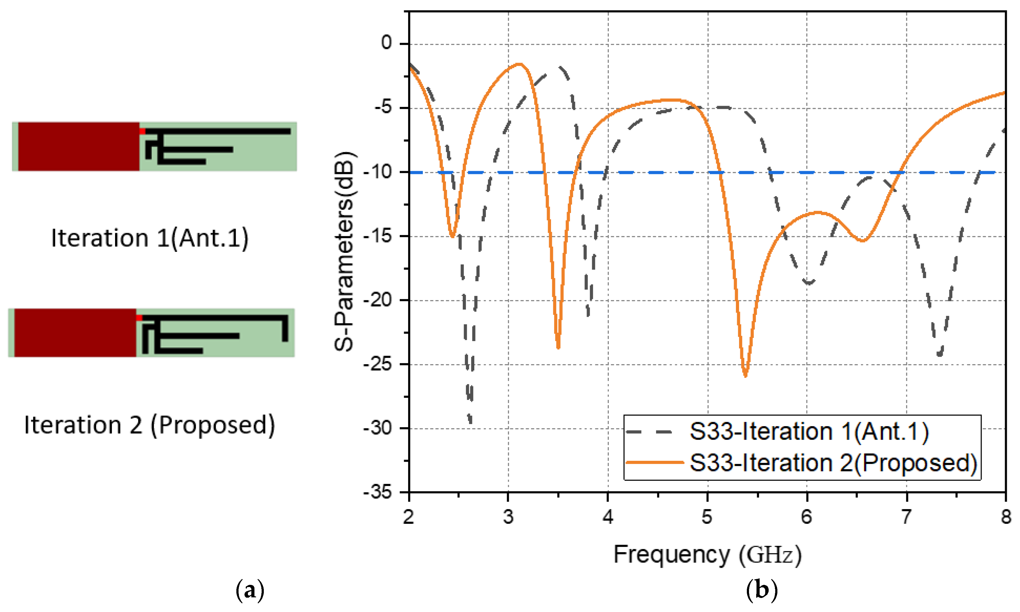
The antenna 3 (Ant. 3) of the second antenna type has the same geometric shape as the antenna 4 (Ant. 4) and is placed in the symmetrical position of the shield. The evolution process of Ant. 3 is described below. The evolution steps and reflection coefficients of the second antenna type are shown in Figure 3. In iteration 1, the size design of the first antenna type is applied to the PET shield and the FR4 substrate. The simulation results show that the resonant frequency band of 5.3 GHz~7.22 GHz originally in the first antenna type is shifted to the resonant frequency band of 5.64 GHz~7.72 GHz, and other resonant frequency bands are also shifted. In iteration 2, the length of W2 is extended to W3 and the microstrip line W4 is added to adjust the resonant frequency band to 5 GHz to 7 GHz. In addition, the length of L2 is slightly increased to L6 to adjust the resonant frequency band between 3.38 GHz and 3.66 GHz.
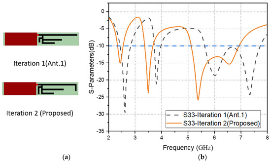
Figure 3.
(a) Evolution steps of Ant. 3, (b) corresponding reflection coefficients (|S33|).
2.2. Effect of Antenna Branch
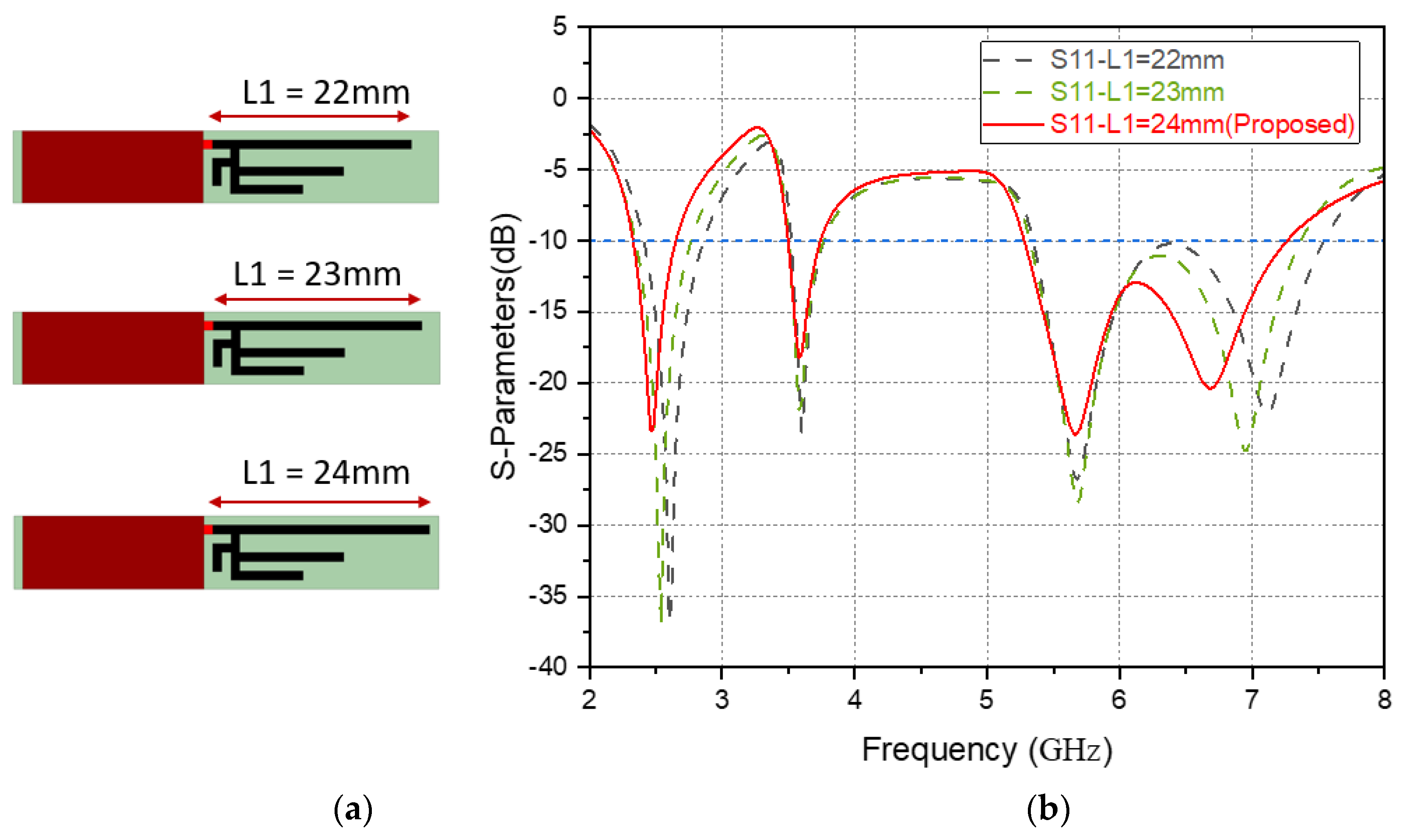
The resonance of the antenna depends on the size and position of the radiating element and the ground plane. First, a simulation comparison is made for the length change of L1 of Ant. 1. As shown in Figure 4, when the length of L1 of Ant. 1 is gradually shortened (L1 = 22 mm and L1 = 23 mm), from the reflection coefficient |S11|, the resonance strength between 5 GHz and 7 GHz is weakened, but it does not have much impact on the 3.5 GHz resonance frequency band.
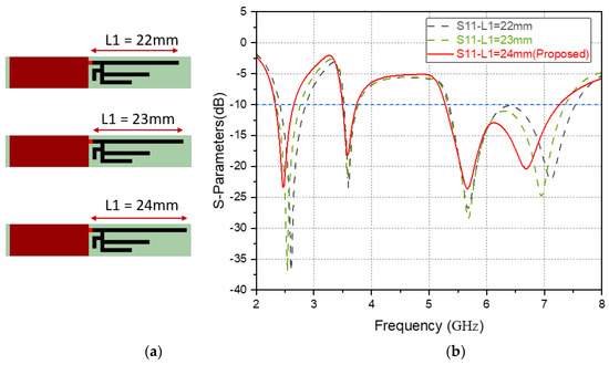
Figure 4.
(a) Schematic diagram of L1 length variation of Ant. 1, (b) reflection coefficient (|S11|) of L1 length variation.
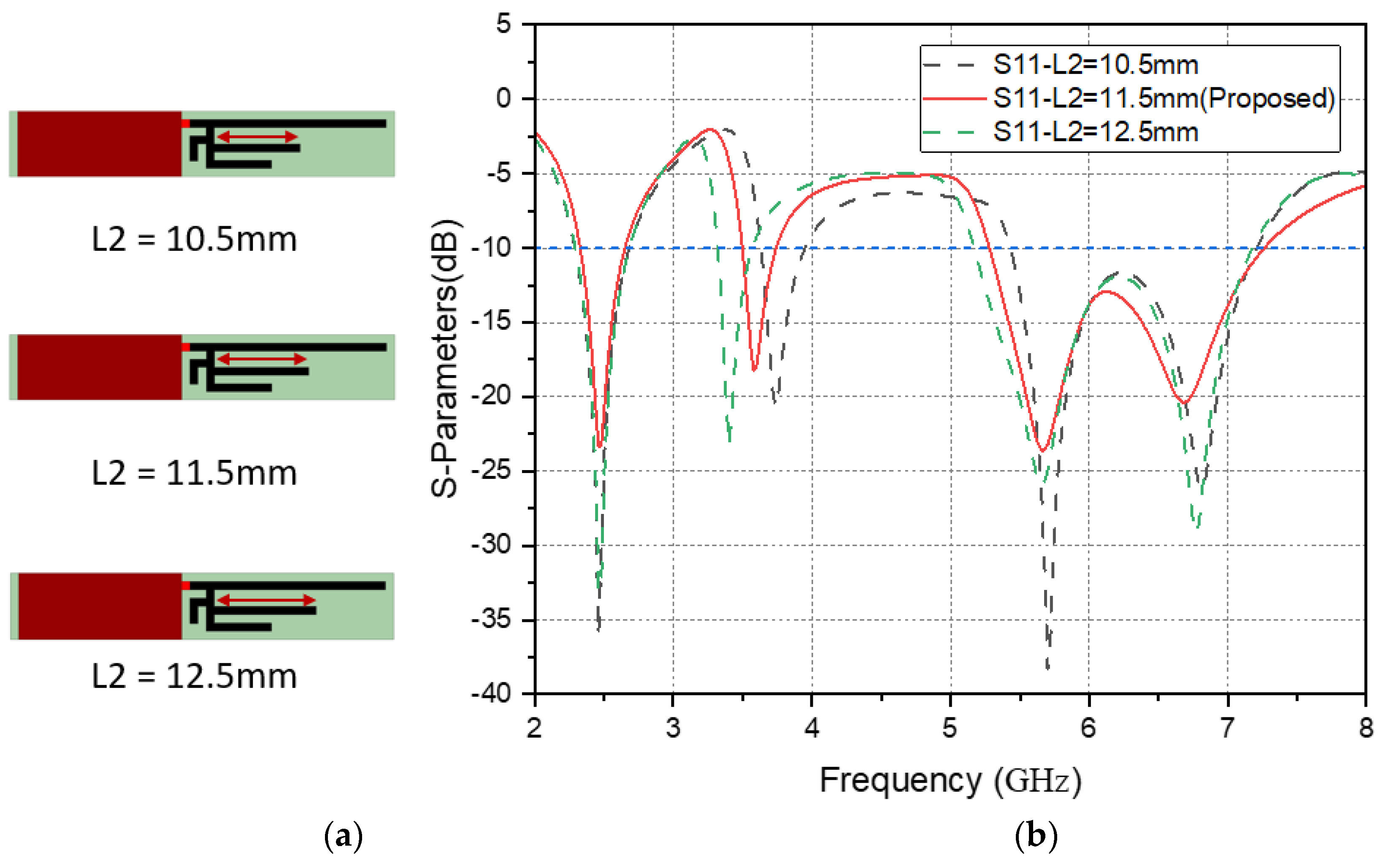
As shown in Figure 5, when the length of L2 of Ant. 1 is 10.5 mm, the resonance point of 3.5 GHz will move to a higher frequency and weaken the resonance strength between 5 GHz and 7 GHz. When the length of L1 is 12.5 mm, the resonance point of 3.5 GHz will move to a lower frequency, the bandwidth of 5 GHz~7 GHz will be narrowed, and the resonance strength between 5 GHz~7 GHz will also be weakened.
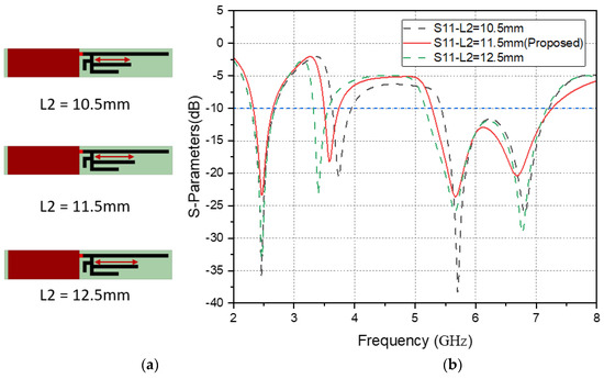
Figure 5.
(a) Schematic diagram of L2 length variation of Ant. 1, (b) reflection coefficient (|S11|) of L2 length variation.
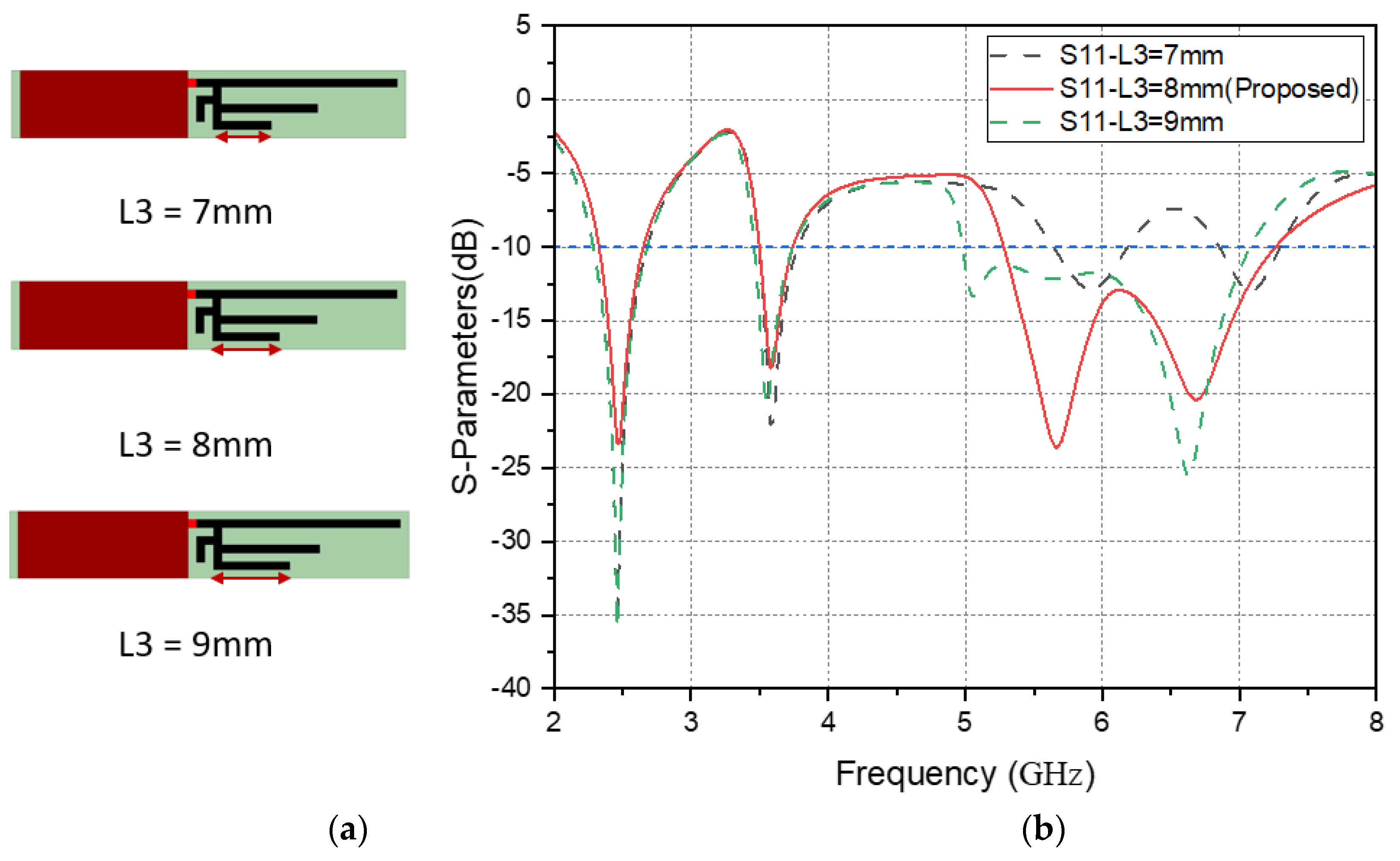
As shown in Figure 6, when the L3 length of Ant. 1 is 7 mm, the resonance point of 5 GHz~7 GHz will move to a higher frequency, and at the same time, the resonance strength between 5 GHz~7 GHz will be greatly weakened. When the length of L3 is 9 mm, the resonance point of 5 GHz~7 GHz will move to a lower frequency, and the resonance strength between 5 GHz~6 GHz will be weakened.
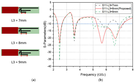
Figure 6.
(a) Schematic diagram of L3 length variation of Ant. 1, (b) reflection coefficient (|S11|) of L3 length variation.
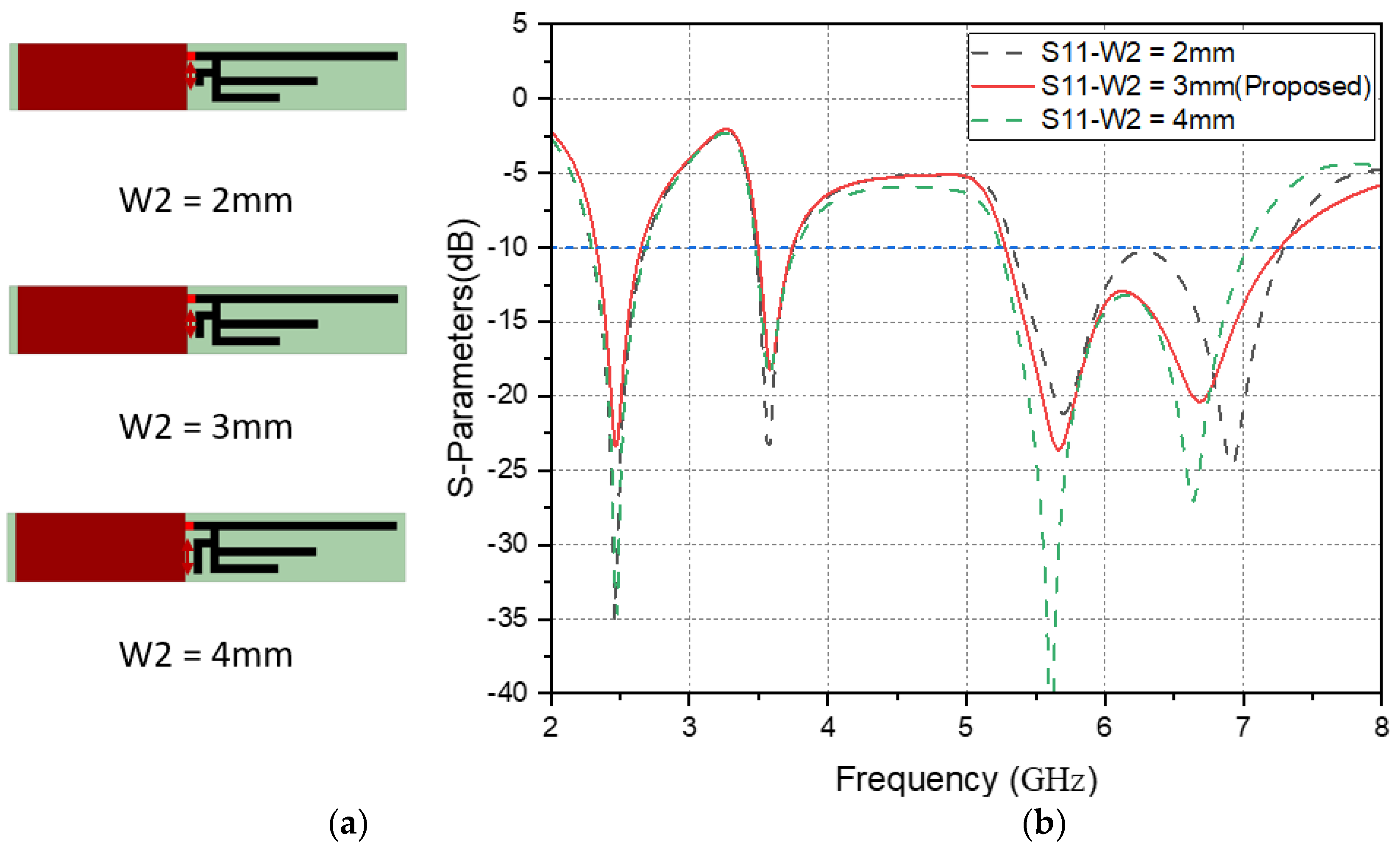
As shown in Figure 7, when the W2 length of Ant. 1 is 2 mm, the resonance strength of 5 GHz to 7 GHz is weakened. When the length of W2 is 4 mm, the resonance intensity of 5 GHz~6 GHz is slightly increased, and the resonance bandwidth is reduced, but whether the length of W2 is increased or decreased has little effect on the resonance point and bandwidth of 2.4 GHz and 3.5 GHz.
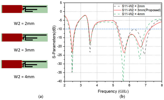
Figure 7.
(a) Schematic diagram of W2 length variation of Ant. 1, (b) reflection coefficient (|S11|) of W2 length variation.
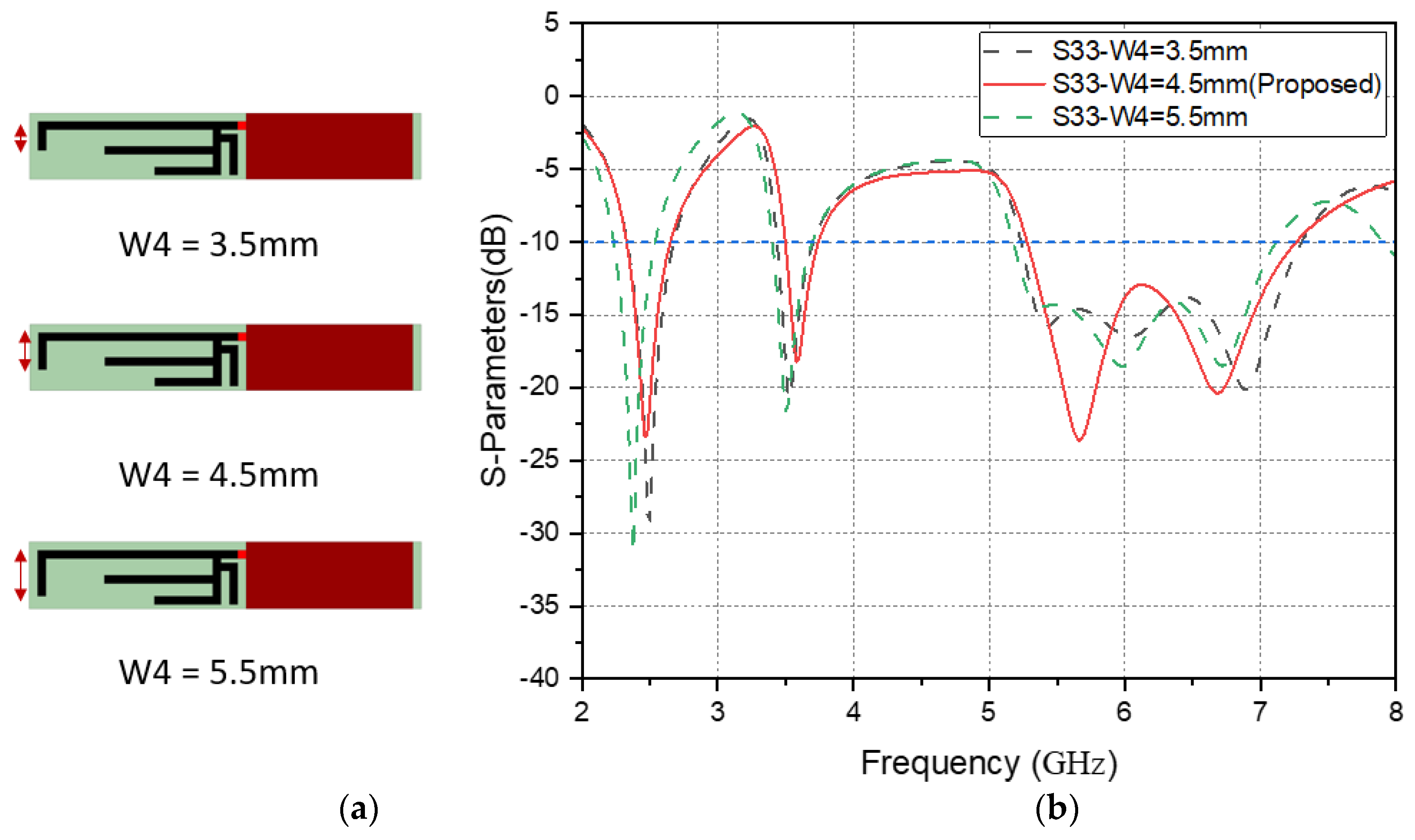
The geometry of the second antenna pattern is similar to that of the first antenna pattern. Therefore, the offset change of the resonance point and frequency of the antenna branches of L5, L6, and L7 of the second antenna type is the same as the resonance point and frequency of the antenna branches of L1, L2, and L3 of the first antenna type. The second type of antenna is only analyzed for the branch of W4. As shown in Figure 8, when the length of W4 of Ant. 3 is 3.5 mm, the resonance strength of 5 GHz~7 GHz is weakened. When the length of W4 is 5.5 mm, the resonance strength of 5 GHz~6 GHz is also weakened. Similarly, whether the length of W4 is increased or decreased has little effect on the resonance point and bandwidth of 2.4 GHz and 3.5 GHz.

Figure 8.
(a) Schematic diagram of W4 length variation of Ant. 3, (b) reflection coefficient (|S33|) of W4 length variation.
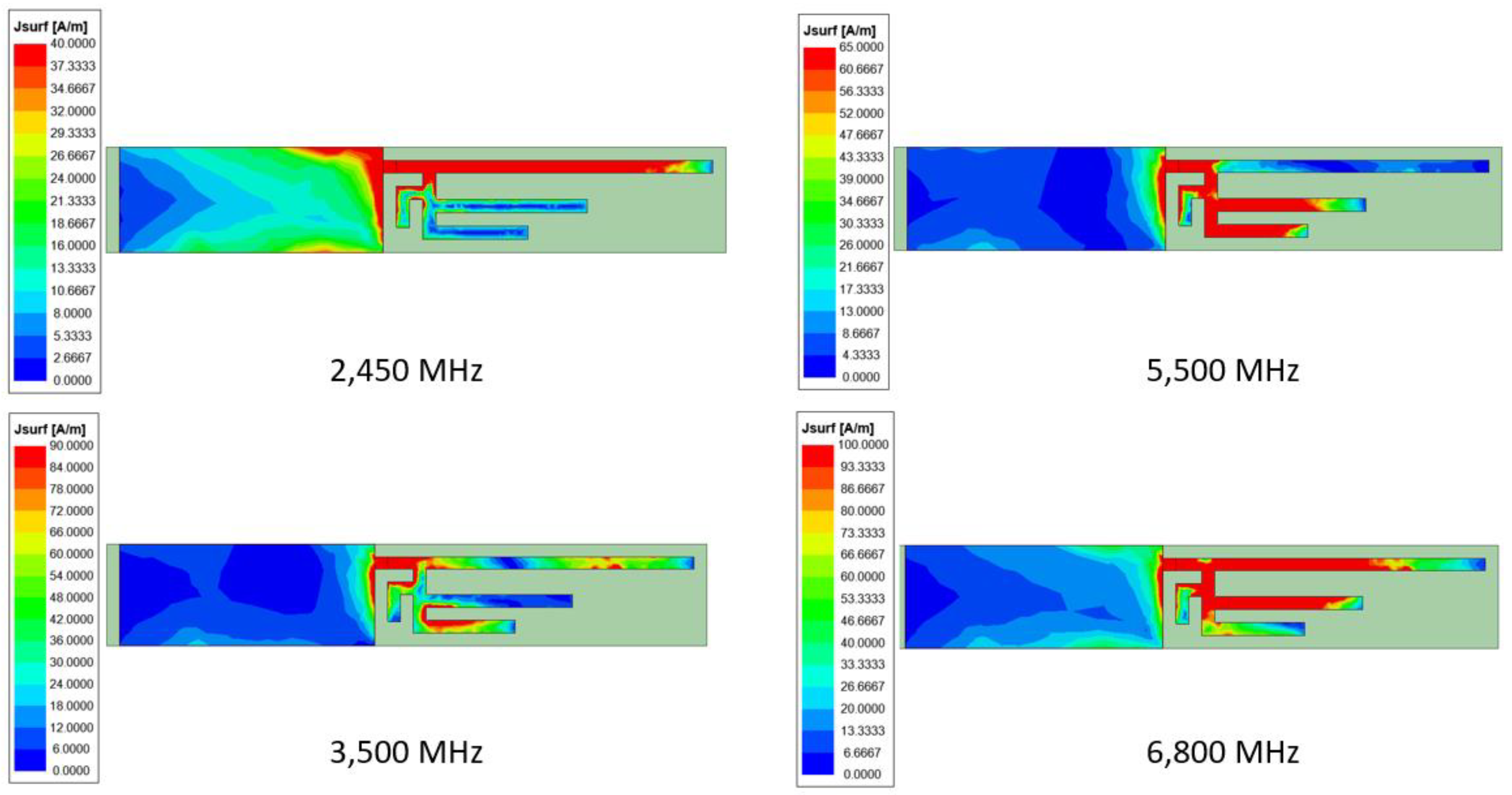
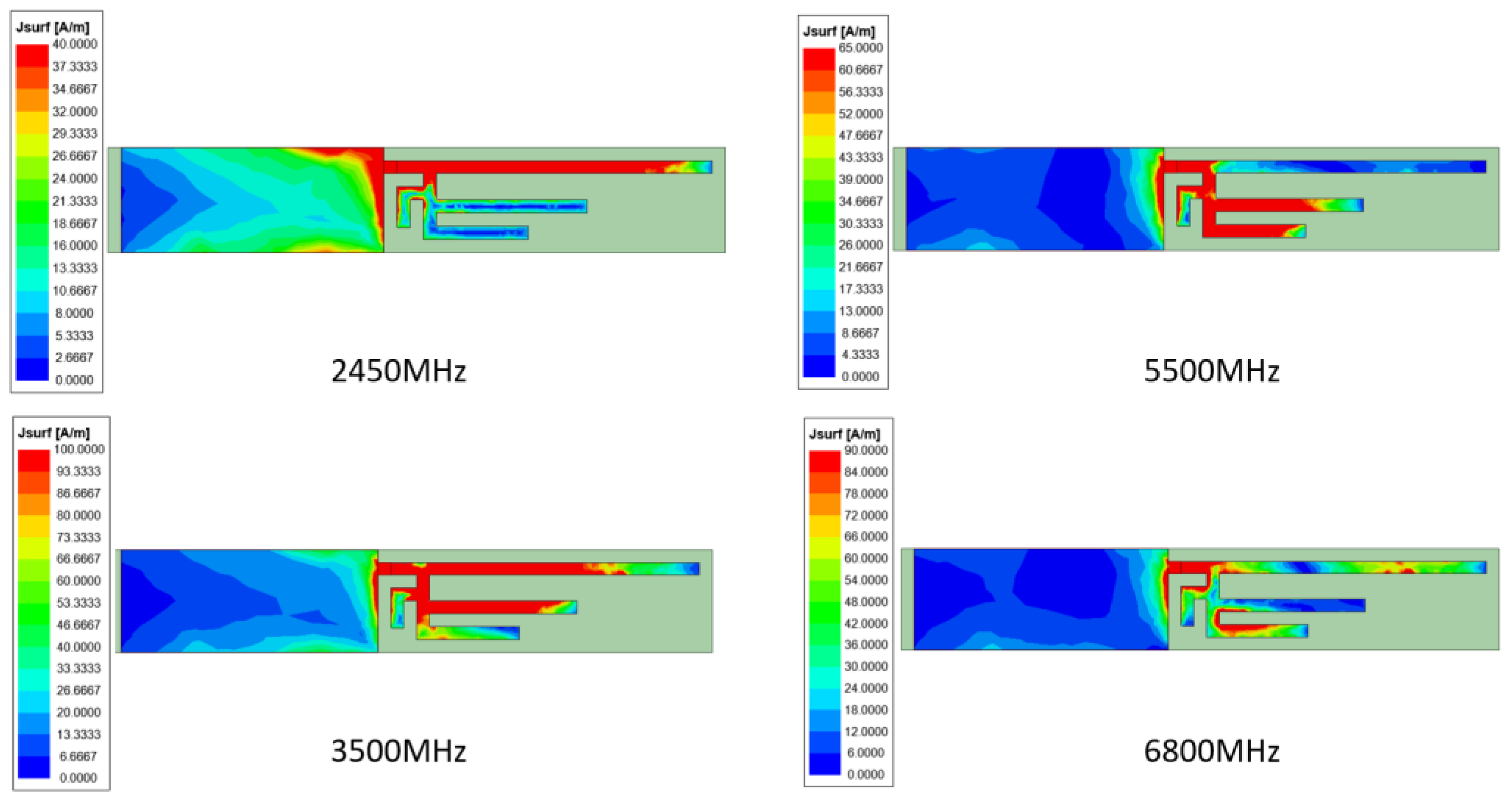
2.3. Surface Current
The working mode of the antenna is to exist in the whole monopole antenna according to the current entering from the feeding point. When the antenna is operating at the desired frequency, the magnitude of the current is greatest and allows electromagnetic waves to radiate away from the antenna.
From the Ant. 1 of Figure 9, the current mainly flows around L1 in the 2.45 GHz band. In the 3.5 GHz band, the surface current of Ant. 1 flows between L2 and the segment of L1 adjacent to L2, and the coupling produces the 3.5 GHz band. For Ant. 1 in the 5.5 GHz band, surface current flows between L3- and L2-adjacent L3 segments and couples to produce the 5.5 GHz band. For Ant. 1 in the 6.8 GHz band, surface current flows between L1 and the metal ground plane and the segment before the branch flow, which also echoes the resonant frequencies of 2.4 GHz and 7 GHz generated by L1 during the evolution analysis of Ant. 1.
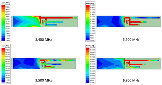
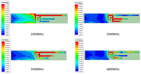
Figure 9.
Surface-current simulation results when the working resonance point of Ant. 1 is located at 2450 MHz, 3500 MHz, 5500 MHz, and 6800 MHz.
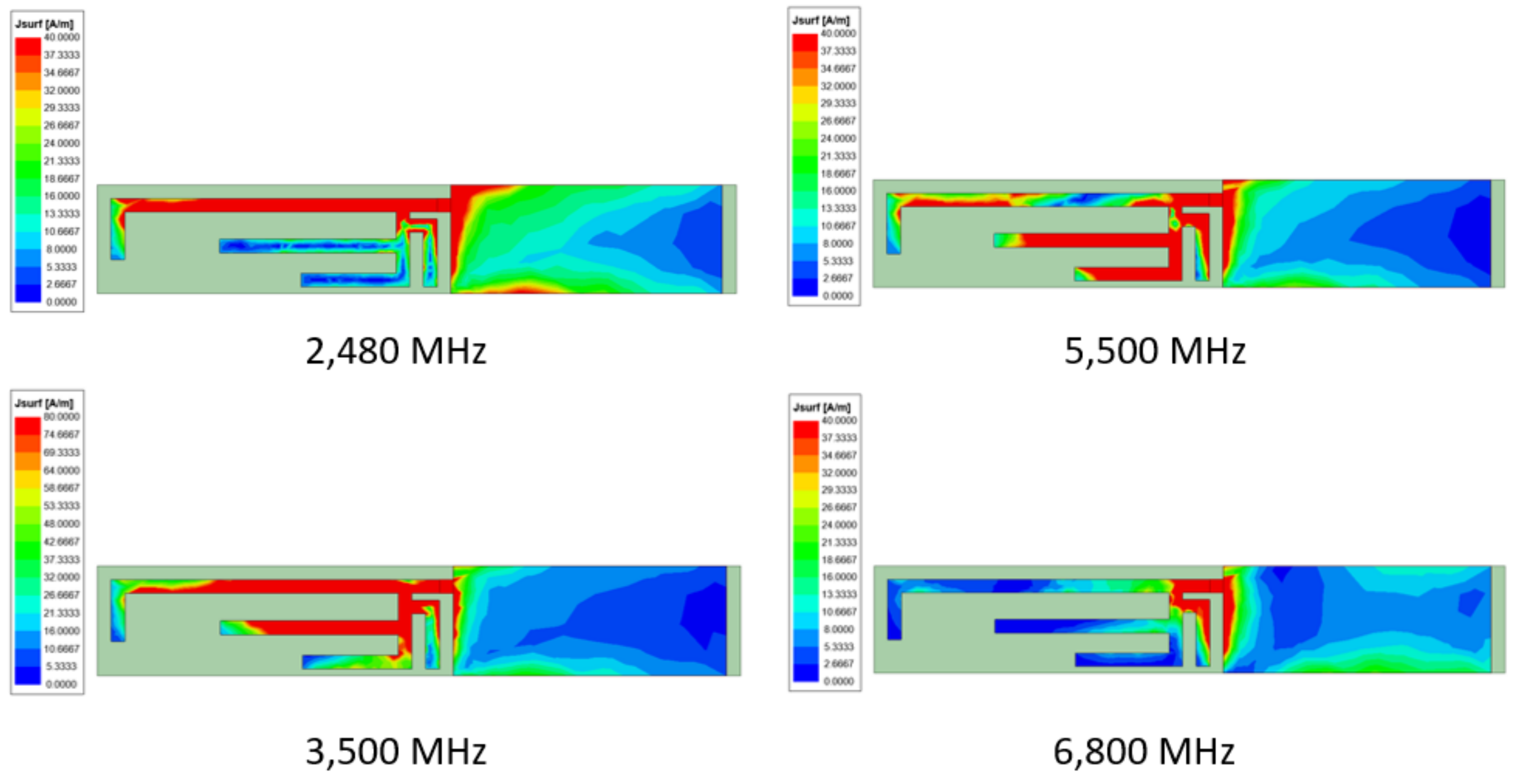
As shown in Figure 10, in the 2.48 GHz band, the current of Ant. 3 mainly flows around L5. For Ant. 1 in the 3.5 GHz frequency band, surface current flows between L6 and L5 in the segment adjacent to L6. For Ant. 3 in the 5.5 GHz band, surface current flows between L7 and L6 in the segment adjacent to L7. In the 6.8 GHz frequency band, the surface current of Ant. 3 flows between L5, the metal ground plane, the segment before the branch, and W4. During the evolution analysis of Ant. 1, L1 generates resonance frequencies of 2.4 GHz and 7 GHz at the same time, and W2 affects the resonance and strength. Ant. 3 is evolved from Ant. 1, so such a current distribution is also related to the resonance of W4 and L5.

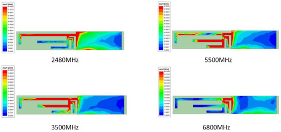
Figure 10.
The surface current simulation results when the working resonance point of Ant. 3 is located at 2480 MHz, 3500 MHz, 5500 MHz, and 6800 MHz.
The final proposed design size of the antenna based on the above-mentioned antenna evolution, antenna branch, and surface current analysis is shown in Figure 11, and the size code in the figure refers to the detailed size table in Table 1.
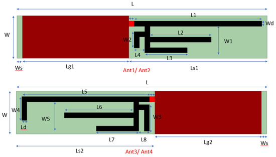
Figure 11.
Ant. 1 and Ant. 3 for the final proposed design.

Table 1.
Detailed Antenna Dimensions.
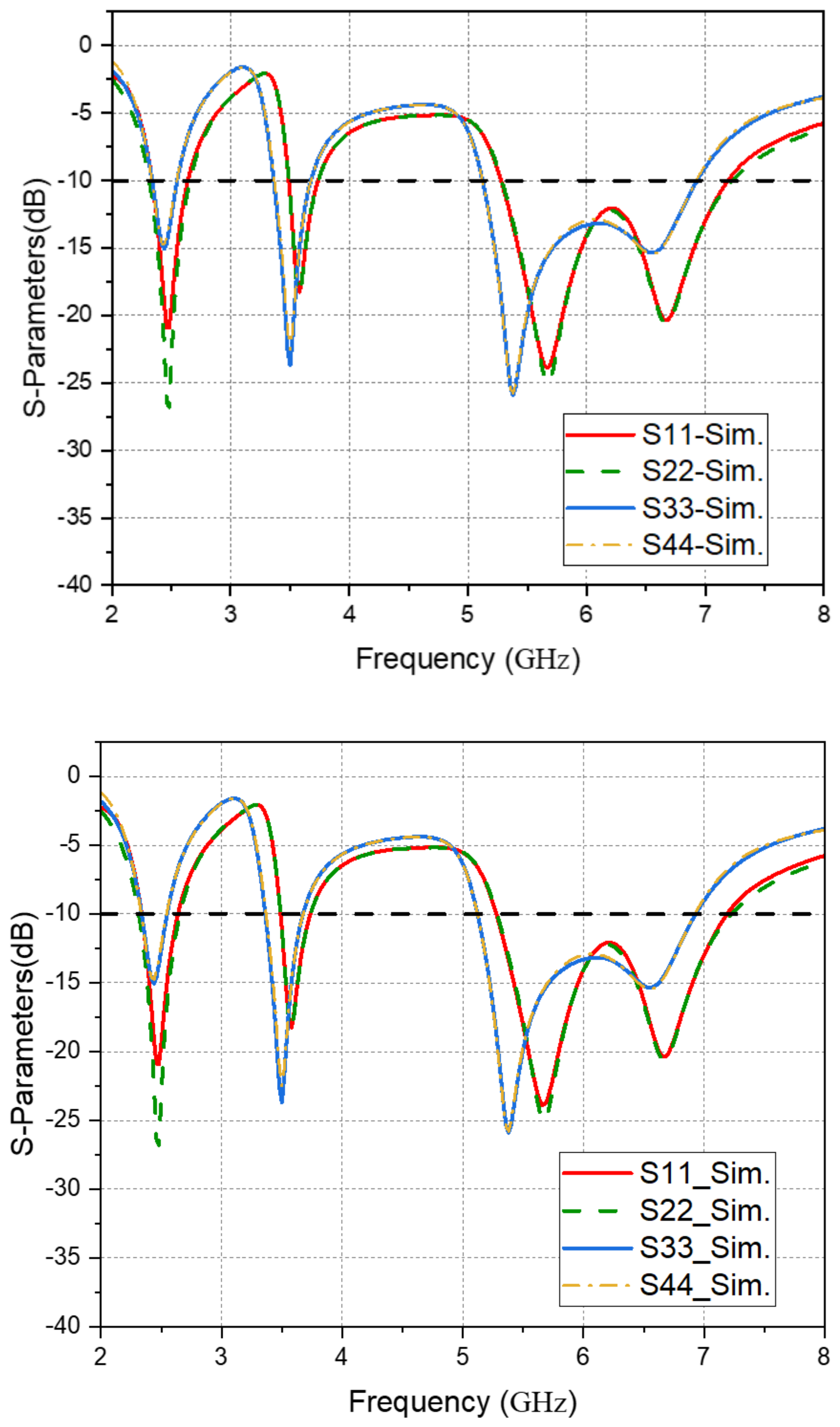
As shown in Figure 12, the reflection coefficients (|S11|, |S22|, |S33|, |S44|) of the final proposed size of the antenna system can reach the operating frequency band and resonance strength of ≤−10 dB covering 5G FR1 and Wi-Fi 7 working frequency bands. Moreover, the working frequency bands and resonances of the antennas 1 and 2 constituting the first antenna type are almost the same, and the working frequency bands and resonances of the antennas 3 and 4 constituting the second antenna type are also almost the same.
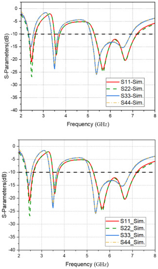
Figure 12.
Reflection coefficients for the final proposed size of the antenna system (|S11|, |S22|, |S33|, |S44|).
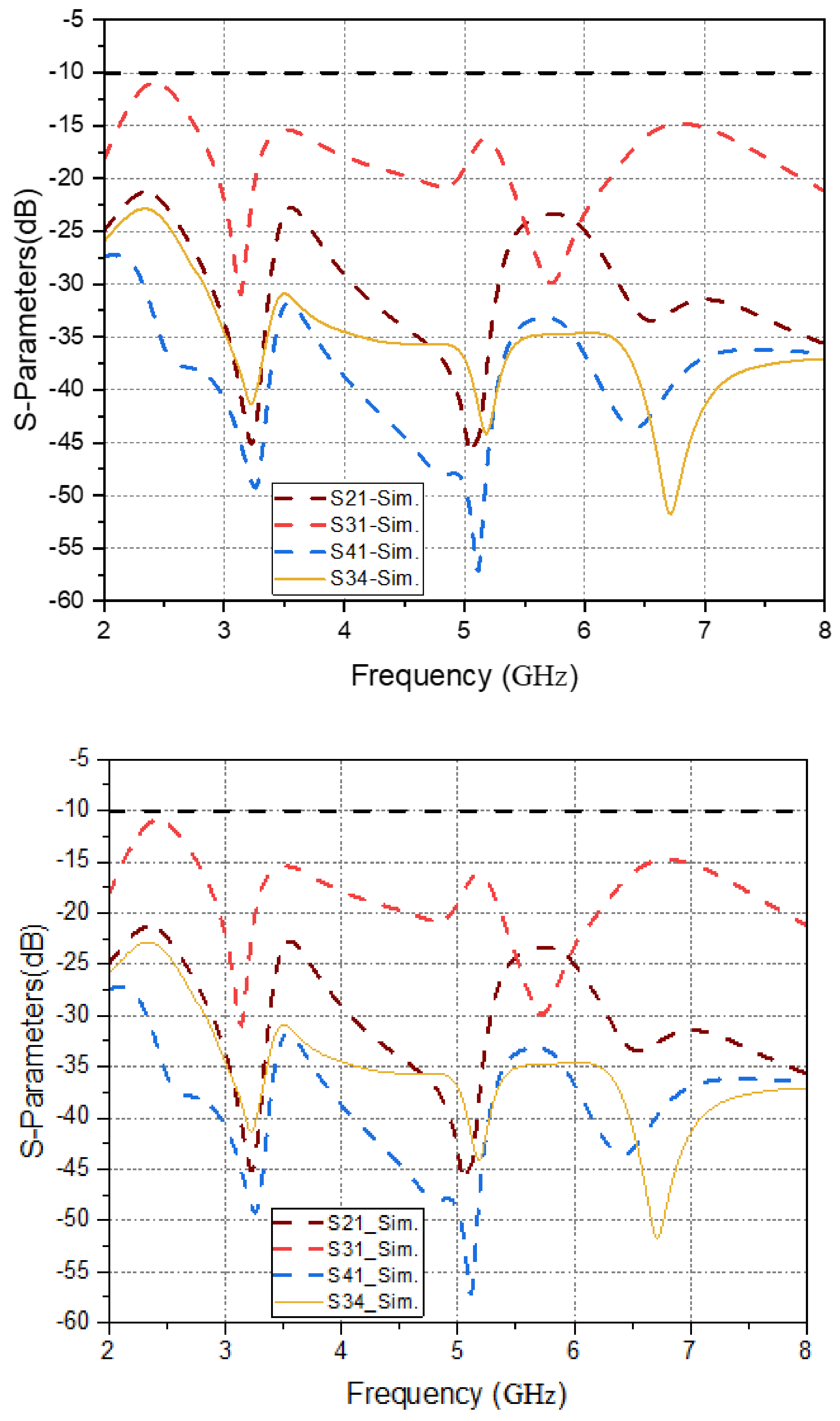
The quality of isolation is very important for MIMO antennas. Ant. 1 and Ant. 2 make full use of the symmetry of the frame and are placed in symmetrical positions on the left and right sides of the frame so that the distance between Ant. 1 and Ant. 2 is at least 20 mm. Ant. 3 and Ant. 4 are placed on symmetrical curved positions on the left and right sides of the shield by utilizing the symmetry of the shield. Only Ant. 1 and Ant. 3, Ant. 2 and Ant. 4 are close to each other. As shown in Figure 13, the isolation between Ant. 1 and Ant. 3 is about −10 dB. The isolation between other antennas is better than −20 dB.
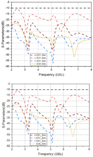
Figure 13.
Isolation for final proposed size of antenna system (|S21|, |S31|, |S41|, |S34|).
3. Antenna Analysis
3.1. S-Parameters Analysis of Antennas
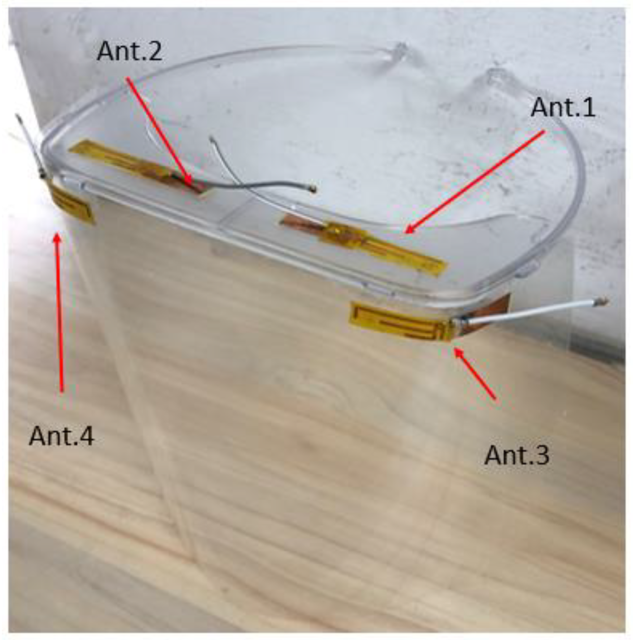
Figure 14 shows the actual architecture diagram of a 5G FR1 and Wi-Fi 7 antenna system for a medical mask proposed in this paper. The antenna system is printed on FR4-substrate material. Each antenna has a 50 ohm feeding connector, and Ant. 1 and Ant. 2 are placed on the left and right sides of the frame, respectively, and Ant. 3 and Ant. 4 are placed on the left and right sides of the shield, respectively. The previous simulation software was placed in the same position.

Figure 14.
Physical diagram of the antenna system on a medical mask.
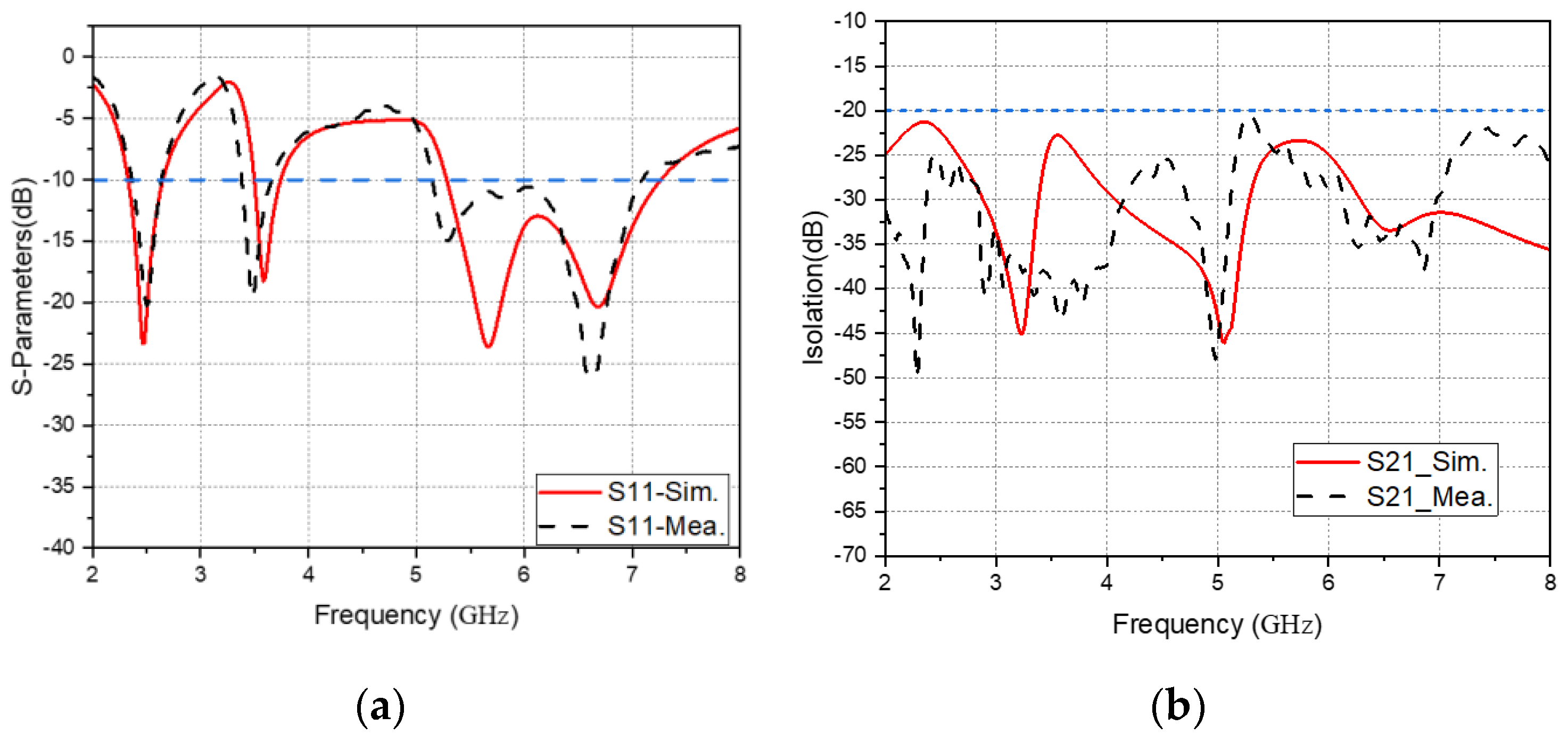
Since Ant. 1, Ant. 2, Ant. 3, and Ant. 4 have symmetry, the following description will take Ant. 1 and Ant. 3 as the representative examples. As shown in Figure 15, the reflection coefficient |S11| of the designed Ant. 1 shows resonant frequencies at 2.46, 3.58, 5.66, and 6.8 GHz. The simulation results cover bandwidths from 2.34 GHz to 2.64 GHz (300 MHz or 12%); 3.5 GHz to 3.74 GHz (240 MHz or 6%); and 5.3 GHz to 7.26 GHz (1960 MHz or 16%). Whereas in the case of measurement results, resonant frequencies are shown at 2.5, 3.48, 5.28, and 6.6 GHz, respectively. The antenna covers a bandwidth of 2.38 GHz to 2.62 GHz (240 MHz or 9.6%); 3.4 GHz to 3.74 GHz (340 MHz or 9.6%); and 5.16 GHz to 7.02 GHz (1800 MHz or 3%). The measured results are in good agreement with simulated frequencies. In addition, the isolation between Ant. 1 and Ant. 2 is lower than 20 dB in both simulation and measurement, indicating that the isolation between Ant. 1 and Ant. 2 is good.
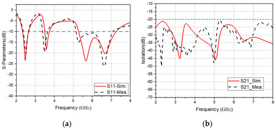
Figure 15.
(a) Simulation and measurement of the reflection coefficient |S11| of Ant. 1, (b) Simulation and measurement of the isolation of Ant. 1 and Ant. 2.
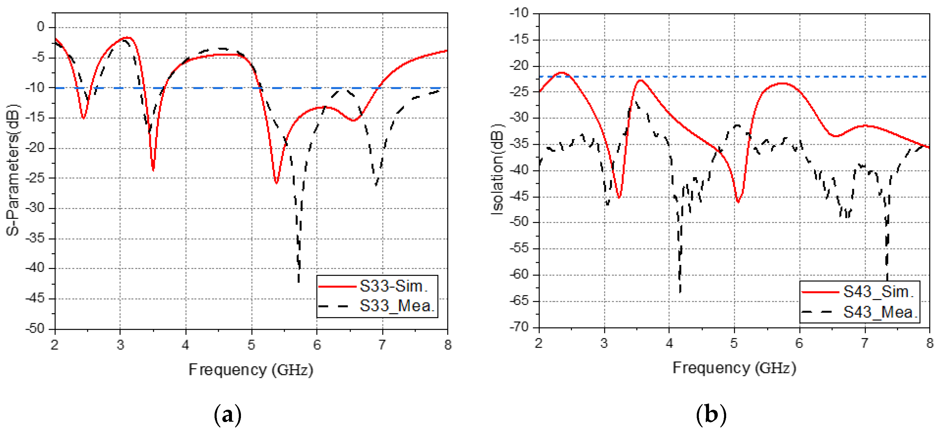
As shown in Figure 16, the reflection coefficient |S33| of the designed Ant. 3 shows resonant frequencies at 2.42, 3.5, 5.38, and 6.56 GHz. The simulation results cover bandwidths from 2.34 GHz to 2.54 GHz (200 MHz or 8%); 3.38 GHz to 3.66 GHz (240 MHz or 8%); and 5.14 GHz to 6.92 GHz (1780 MHz or 29.5%). Whereas in the case of the measurement results, resonant frequencies are shown at 2.52, 3.44, 5.38, and 6.56 GHz, respectively. The antenna covers bandwidths of 2.44 GHz to 2.62 GHz (180 MHz or 7%) and 3.3 GHz to 3.64 GHz (340 MHz or 9.8%). The measured results are in good agreement with the simulated frequencies. However, 5.14 GHz to 8 GHz (2860 MHz or 44%) is slightly different from the analog frequency. The data deviation of the above measurement and simulation may come from the difference between the actual processed value of the dielectric constant of the FR4 substrate and the simulated value, the difference between the actual processing size of the antenna branch and the simulated value, and introducing the measurement coaxial cable into the actual model for measurement needs, etc. The isolation between Ant. 3 and Ant. 4 are lower than 20 dB in both simulation and measurement, indicating that Ant. 3 and Ant. 4 have good isolation.
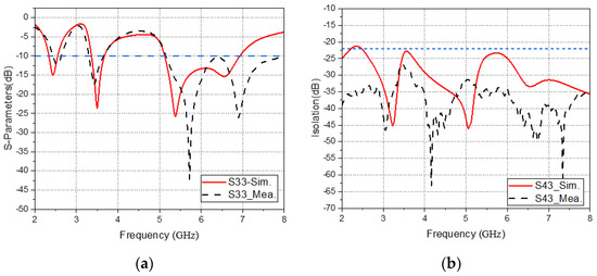
Figure 16.
(a) Simulation and measurement of the reflection coefficient |S33| of Ant. 3, and (b) simulation and measurement of the isolation of Ant. 3 and Ant. 4.
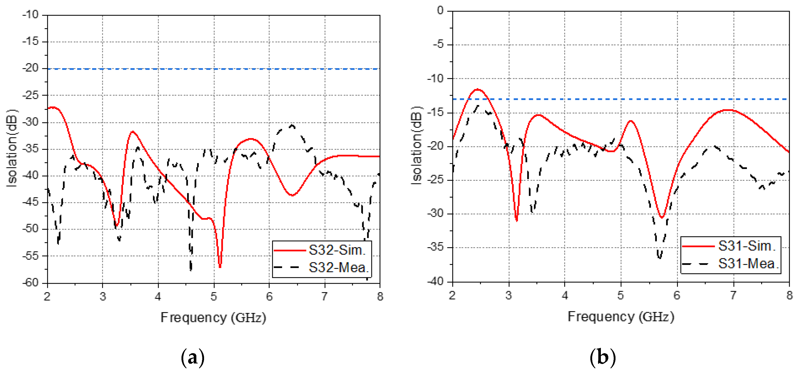
As shown in Figure 17, the isolation of Ant. 2 and Ant. 3 is lower than 30 dB in both simulation and measurement, while the simulation and measurement of the isolation between Ant. 1 and Ant. 3 are both lower than 10 dB. The reason for the good isolation between the antennas 1 and 2, the antennas 3 and 4, and the antennas 2 and 3 is that the antennas are placed at least 20 mm apart. The isolation of Ant. 1 and Ant. 3 is poor because Ant. 1 and Ant. 3 are placed adjacent to the position of the frame and the shield up and down.
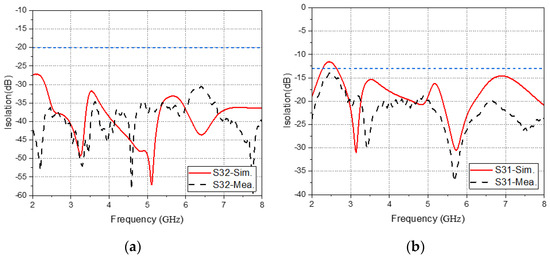
Figure 17.
(a) Simulation and measurement of isolation of Ant. 2 and Ant. 3 (b) simulation and measurement of isolation of Ant. 1 and Ant. 3.
3.2. Gain and Efficiency of Antenna
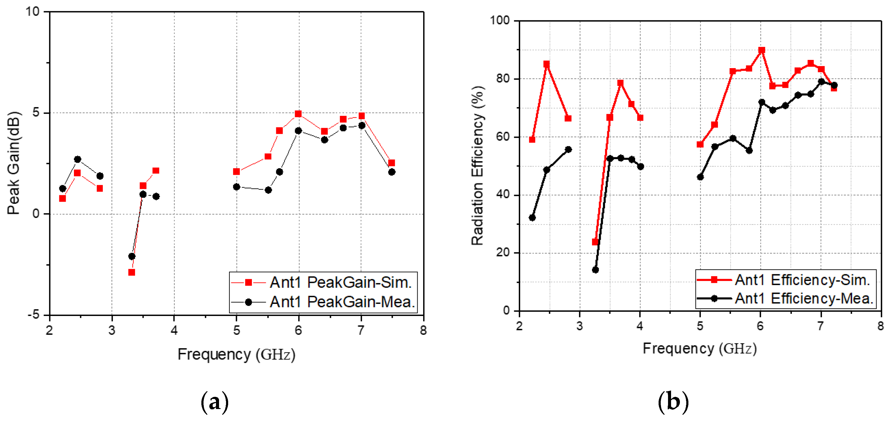
In this paper, the gain and radiation efficiency of the antenna are compared. Figure 18a shows that the simulated peak gain of Ant. 1 is 2, 1.4, 4.9, and 4.8 dB at 2.45, 3.5, 6, and 7 GHz, respectively, while the measured antenna gain is 2.7 dB at 2.45 GHz; 0.9 dB at 3.5 GHz; 4.13 dB at 6 GHz; and 4.39 dB at 7 GHz. As Figure 18b shows, the simulated efficiency peaks of Ant. 1 at 2.45, 3.5, 6, and 7 GHz are 85%, 66%, 71%, and 83%, respectively, while the measured antenna gain is 48% at 2.45 GHz; 48% at 3.5 GHz; 71% at 6 GHz; and 79% at 7 GHz.

Figure 18.
(a) Simulated and measured gain values of Ant. 1, (b) simulated and measured efficiency values of Ant. 1.
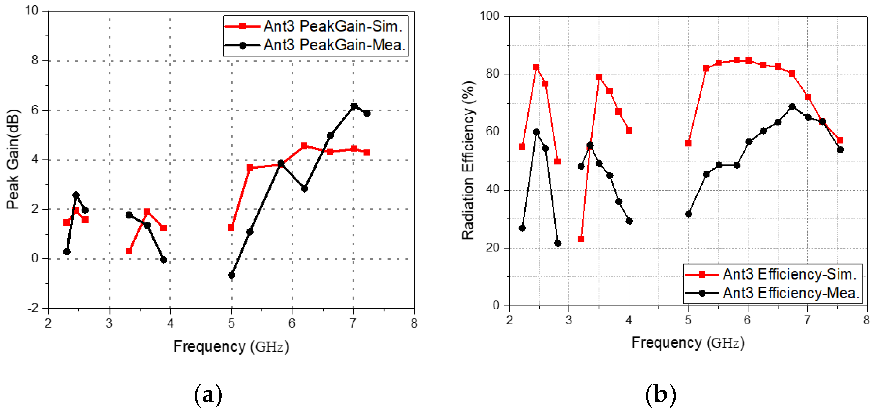
Figure 19a shows that the simulated peak gain of Ant. 1 is 2, 1.8, 4.5, and 4.4 dB at 2.45, 3.5, 6, and 7 GHz, respectively, while the measured antenna gain is 2.56 dB at 2.45 GHz; 1.3 dB at 3.5 GHz; 2.8 dB at 6 GHz; and 6.1 dB at 7 GHz. As Figure 18b shows, the simulated efficiency peaks of Ant. 1 are 82%, 79%, 84%, and 72% at 2.45, 3.5, 6, and 7 GHz, respectively, while the measured antenna gain is 60% at 2.45 GHz; 60% at 3.5 GHz; 56% at 6 GHz; and 65% at 7 GHz.
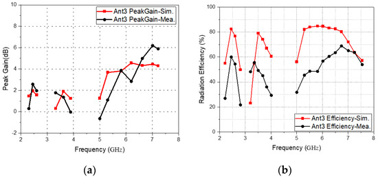
Figure 19.
(a) Simulated and measured gain values of Ant. 3, (b) simulated and measured efficiency values of Ant. 3.
The power losses are caused by mismatches between the antenna elements and the feed network. In addition, the antenna material itself loses energy and generates undesired heat, and the radiation of electromagnetic waves from the antenna material also causes some losses. These losses allow the antenna to transmit less than 100% of the energy supplied to it, and the actual measured antenna efficiency is also often between 50–60%; the measured efficiency results are lower than the simulation due to reasonable losses.
3.3. Radiation Pattern
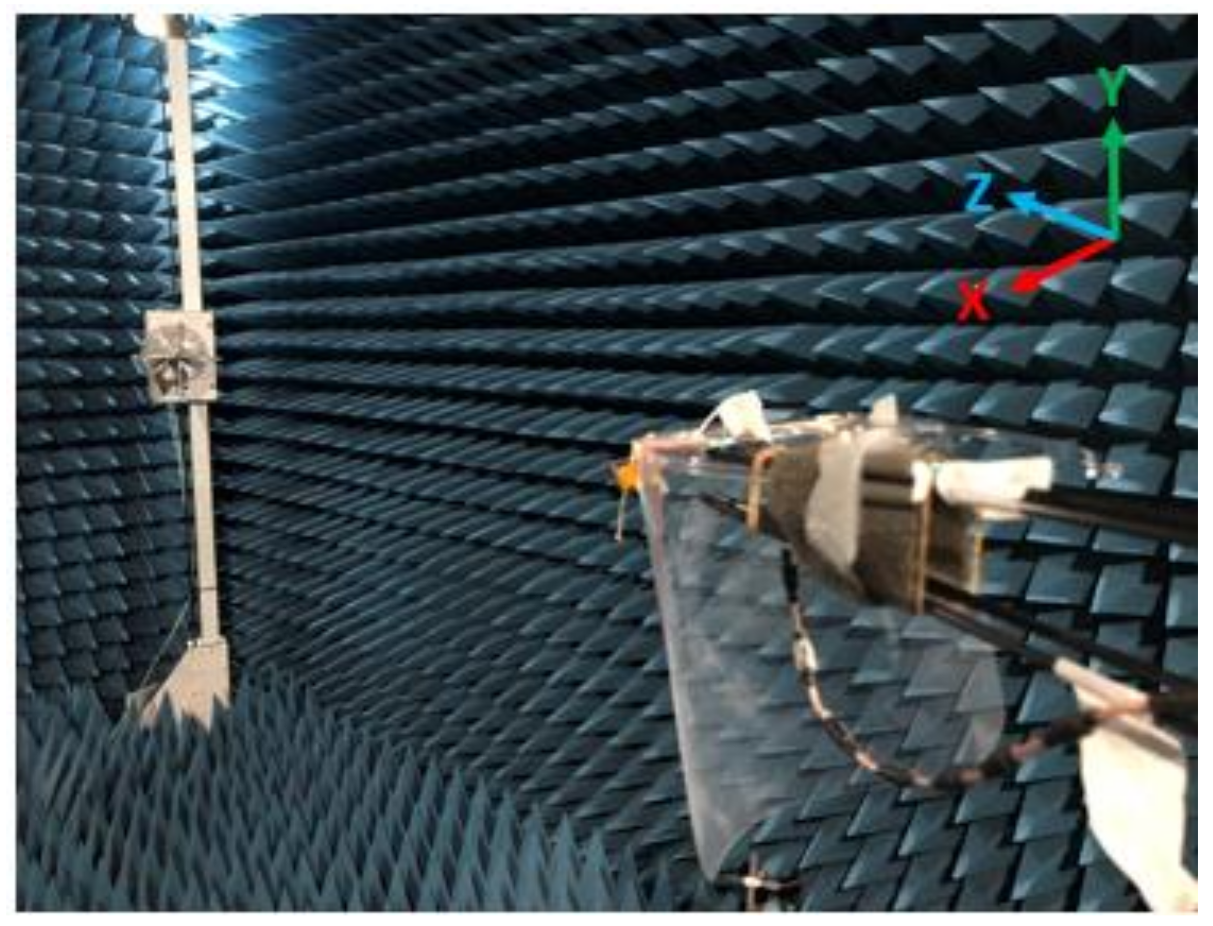
It can seen from the simulation results in Figure 12 that the resonant modes of Ant. 1 and Ant. 2 are very similar, and the resonant modes of Ant. 3 and Ant. 4 are also very similar. Therefore, the following far-field tests are performed with Ant. 1 and Ant. 3. The measurement field used this time is a standard far-field anechoic chamber, the model of the network analyzer is Anritsu MS46524B, and the measurement frequency band of the Horn antenna in the anechoic chamber is 0.1–8 GHz. Figure 20 below is a photo of the test environment of the medical mask in the far-field darkroom, and it is erected according to the XYZ axis of the simulation software corresponding to the XYZ axis of the darkroom.

Figure 20.
Photo of the erection of the medical mask in the far-field darkroom.
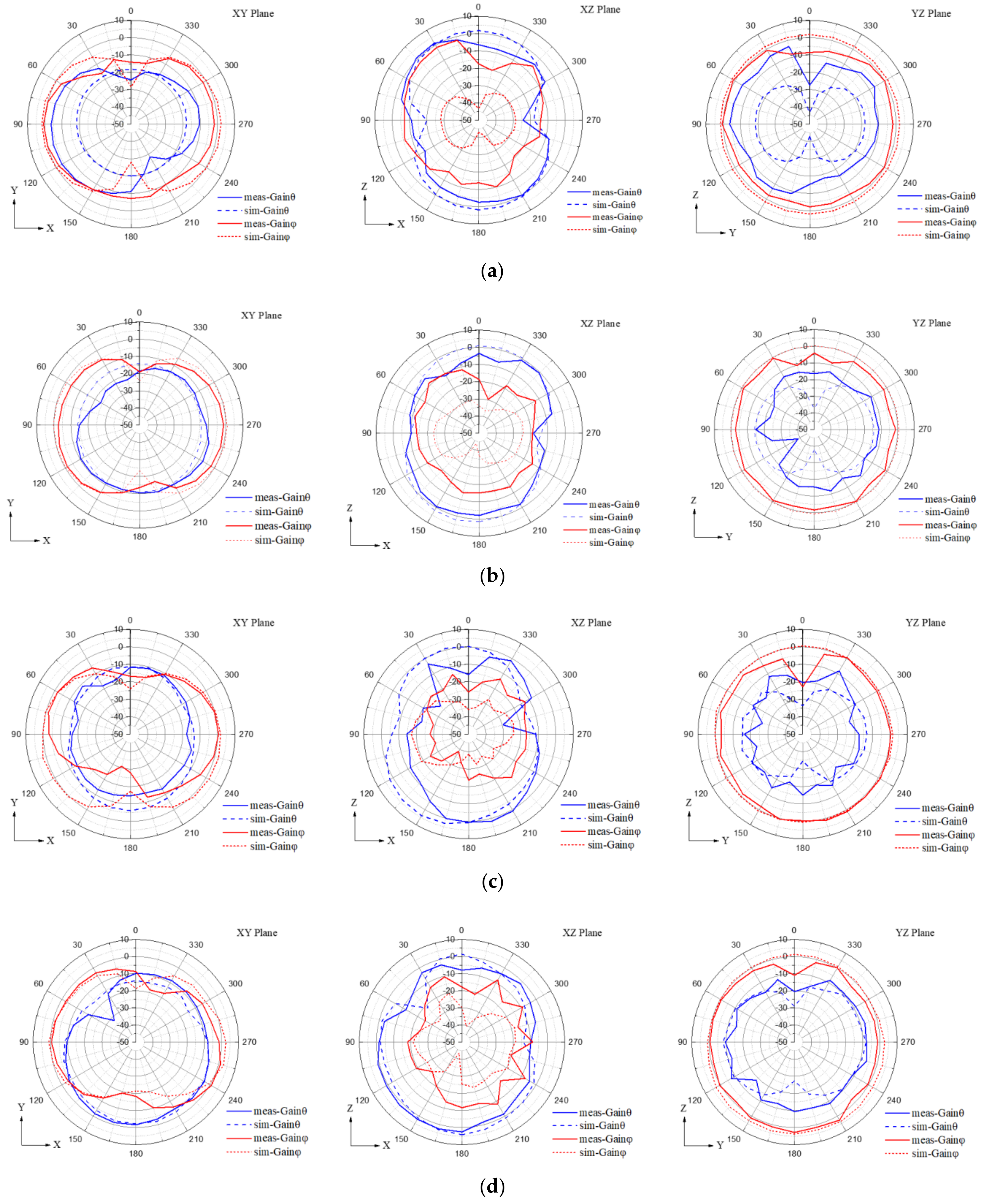
Figure 21 is a 2D gain pattern diagram of Ant. 1 of the simulation and medical mask in the XY plane, the XZ plane, and the YZ plane. It can be found from the figure that when Ant. 1 operates at the resonance points of 2.45 GHz, 3.5 GHz, 5.5 GHz and 6.8 GHz, the simulated and measured radiation modes have the same trend.
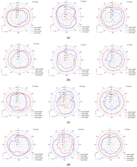
Figure 21.
2D gain simulation and measurement comparison results for Ant. 1. (a) 2.45 GHz; (b) 3.5 GHz; (c) 5.5 GHz; (d) 6.8 GHz.
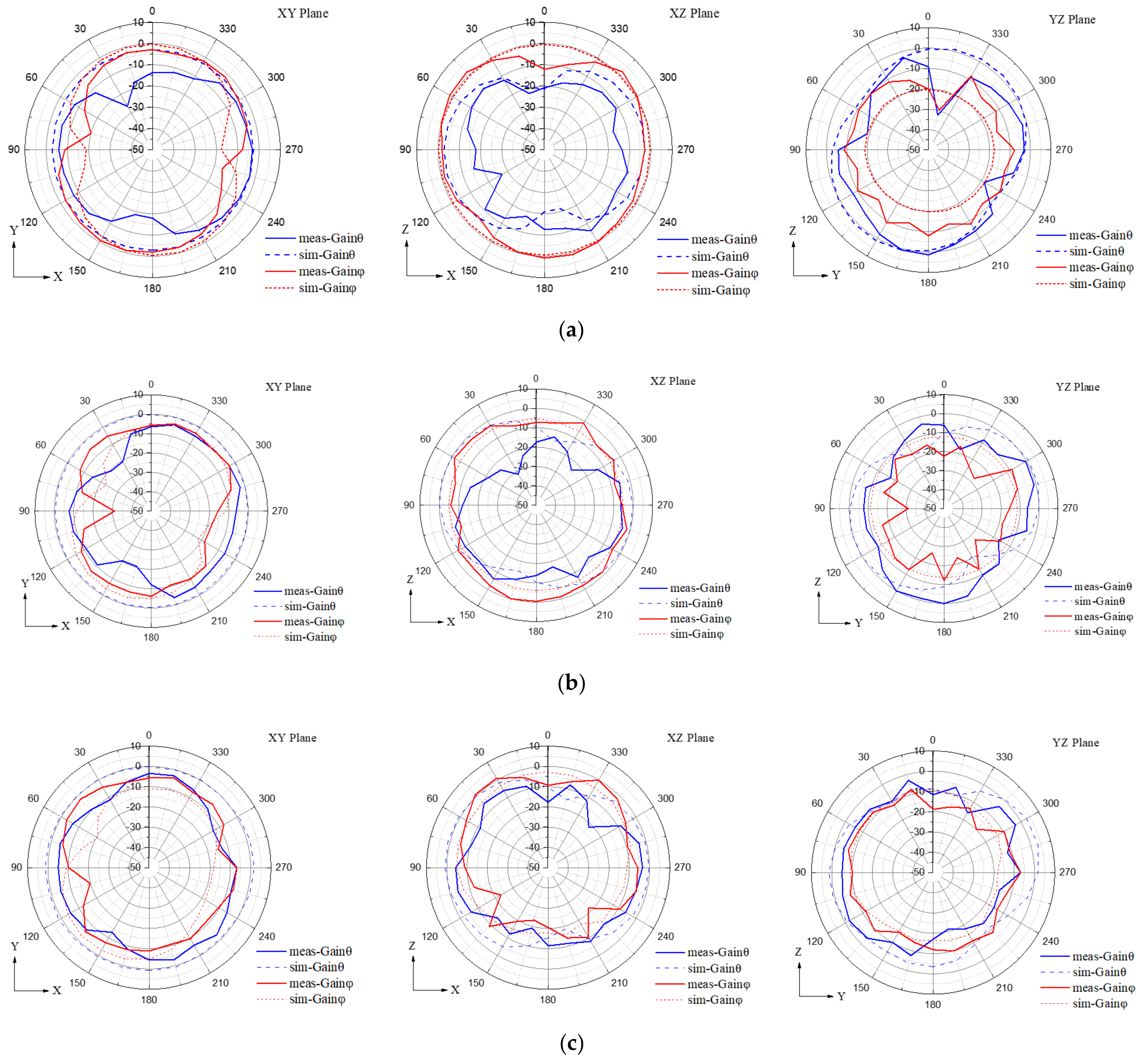
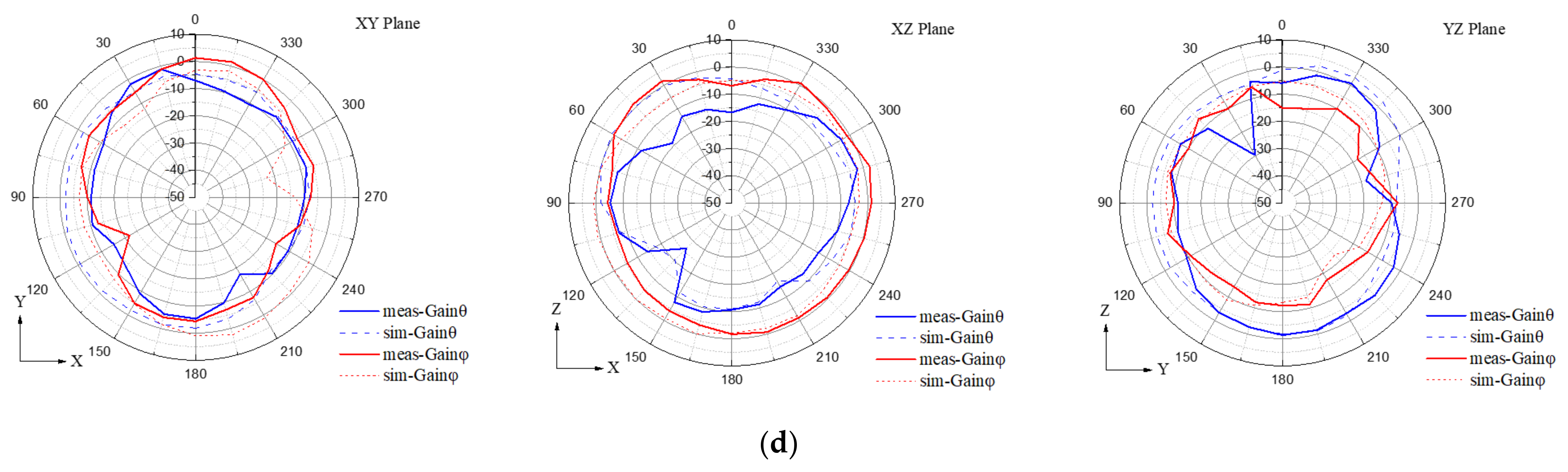
Figure 22 is a 2D gain pattern diagram of Ant. 3 of the simulation and medical mask in the XY plane, the XZ plane, and the YZ plane. It can be found from the figure that when Ant. 3 operates at the resonance points of 2.45 GHz, 3.5 GHz, 5.5 GHz, and 6.8 GHz, the simulated and measured radiation modes have the same trend.
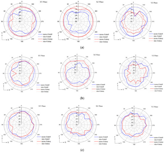
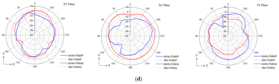
Figure 22.
2D gain simulation and measurement comparison results for Ant. 3. (a) 2.45 GHz; (b) 3.5 GHz; (c) 5.5 GHz; (d) 6.8 GHz.
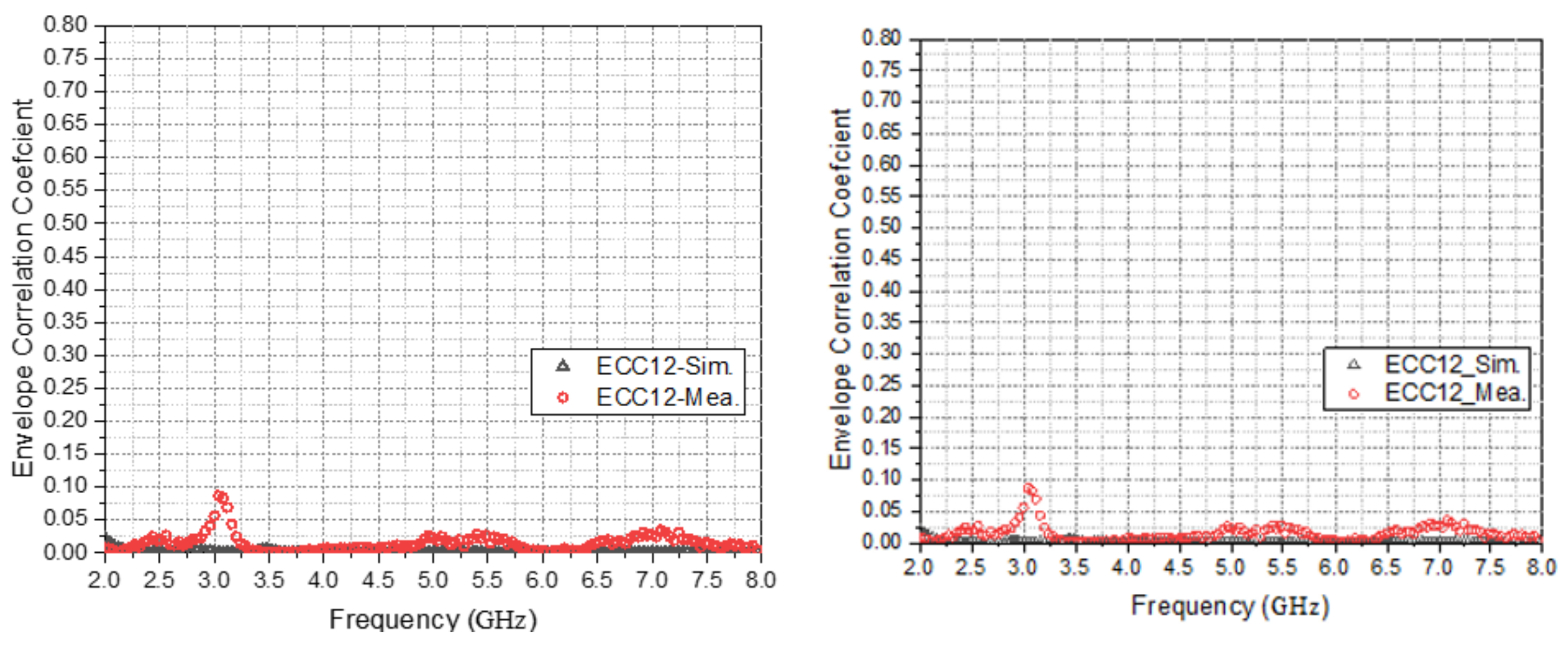
3.4. ECC Simulation and Analysis
The Envelope Correlation Coefficient (ECC) is an important index to measure the performance of the MIMO antenna system. Figure 23, Figure 24, Figure 25 and Figure 26 show the simulation and measurement results of the ECC of the medical mask in free space. It can found that in the effective working frequency band, the measured and simulated ECC values do not exceed 0.05, and the independence of Ant. 1 and Ant. 2, Ant. 3 and Ant. 4, Ant. 1 and Ant. 3, and Ant. 1 and Ant. 4 is good.
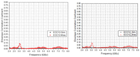
Figure 23.
Comparison of ECC simulation and actual measurement between Ant. 1 and Ant. 2.
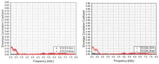
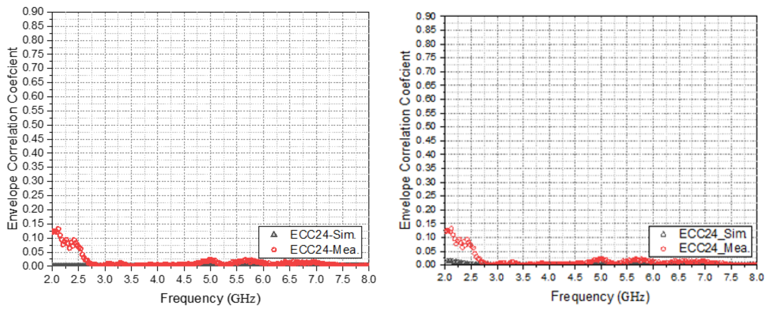
Figure 24.
Comparison of ECC simulation and measurement between Ant. 3 and Ant. 4.
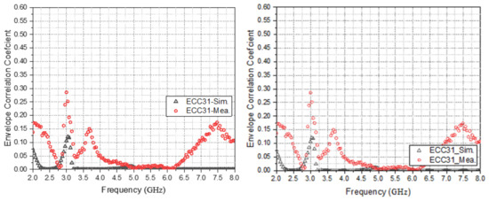
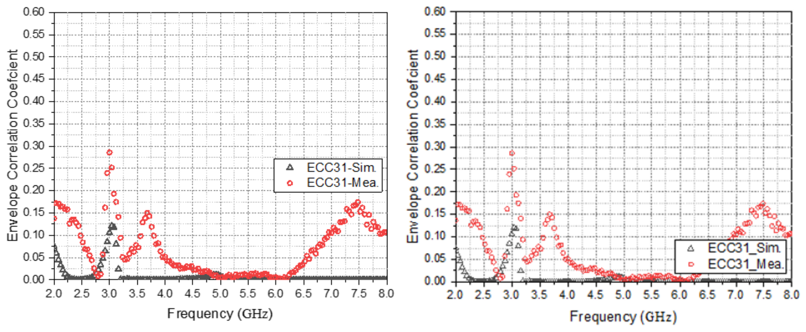
Figure 25.
Comparison of ECC simulation and actual measurement between Ant. 1 and Ant. 3.
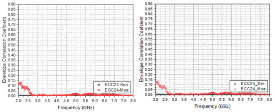
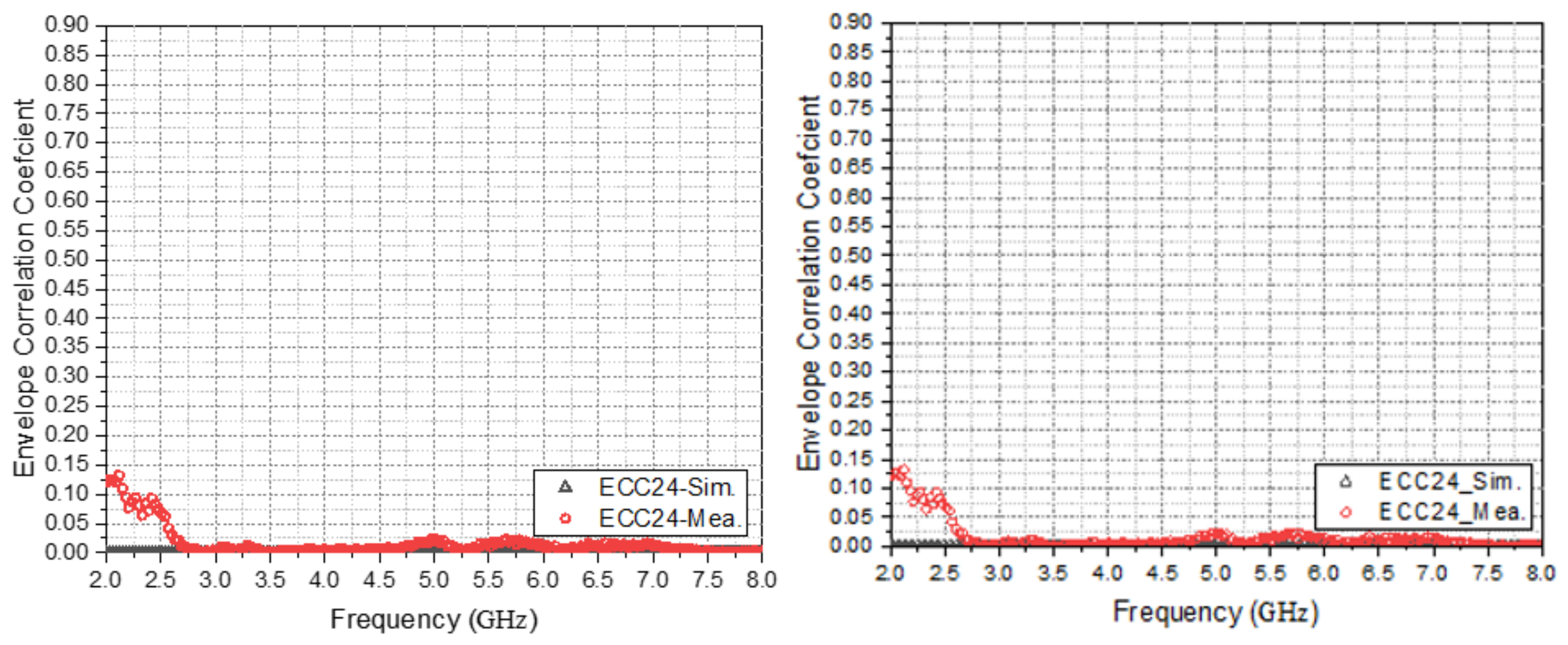
Figure 26.
Comparison between ECC simulation and measurement of Ant. 1 and Ant. 4.
In summary, the measurement results of the antenna show that when the operating frequency band is 2.45 GHz, the gain of the antenna is 2.7 dB, and the efficiency reaches 60%. When the operating frequency band of the antenna is 3.5 GHz, the gain is 1.3 dB, and the efficiency reaches 52%. When the operating frequency band of the antenna is 6 GHz, the gain of the antenna is 4.13 dB, and the efficiency of the antenna is 71%. When the operating frequency band of the antenna is 7 GHz, the gain of the antenna is 6.1 dB, and the efficiency of the antenna is 79%. For the Multiple-Input Multiple-Output (MIMO) antenna system, the isolation is better than −10 dB. The measured Envelope Correlation Coefficient (ECC) is lower than 0.5. This indicates that this antenna is less susceptible to interference during data transmission.
4. Human Body Effect Analysis
4.1. Human Head Model
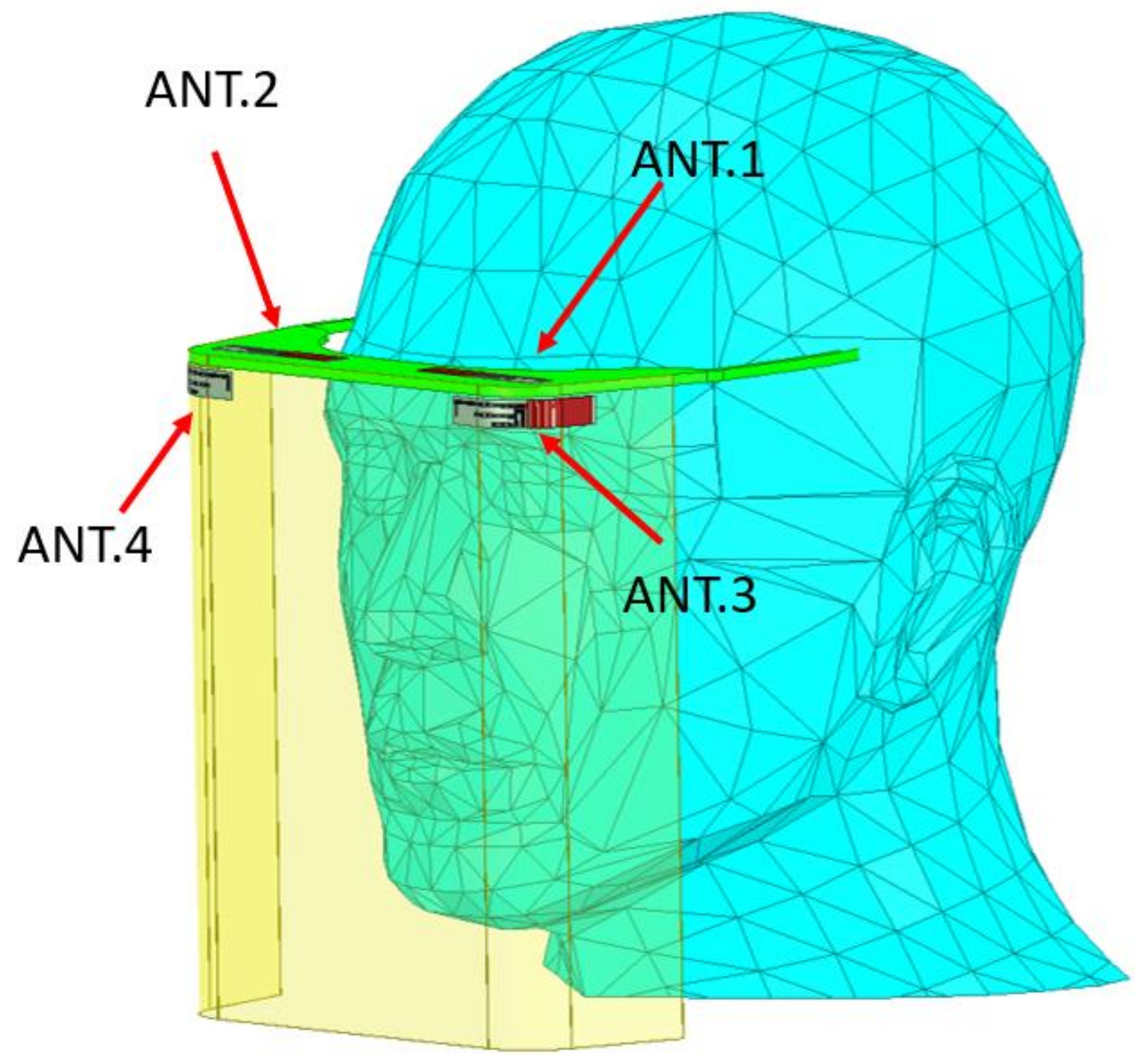
Due to the high dielectric constant of the human body, the resonant frequency of the antenna is lower than that of the free-space antenna. Therefore, it is necessary to simulate and measure the designed antenna system in the human head model and observe whether the antenna performance is affected, to confirm the applicability of the antenna system of the medical mask. Whether it is suitable for wearing on the human body and its performance are analyzed. Figure 27 shows the result of using HFSS to design a medical mask and hanging it on a human head model.
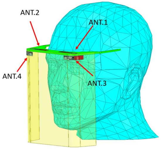
Figure 27.
Medical mask with antenna system worn on human head model.
4.2. Analysis of Free Space and Wearing Head
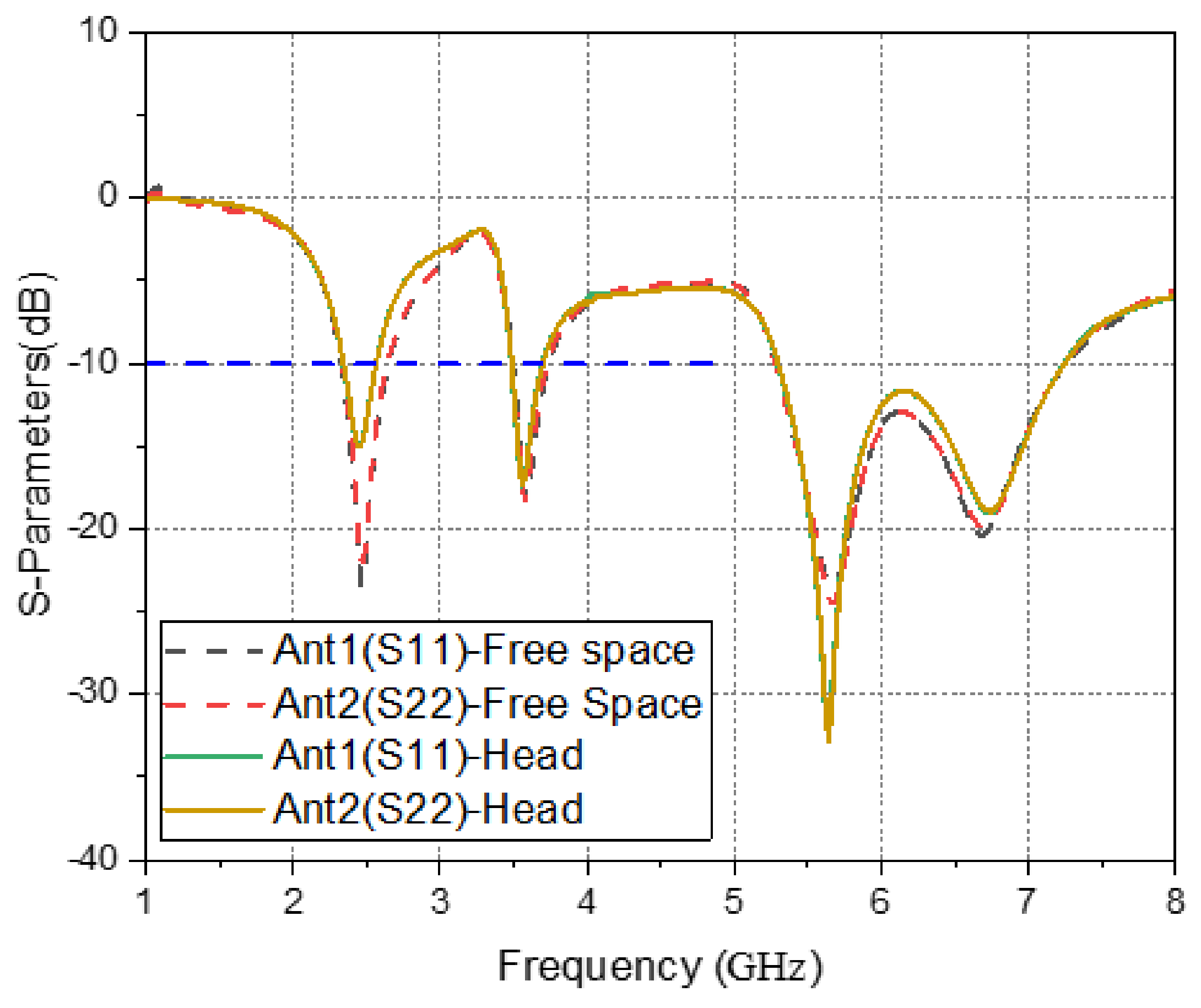
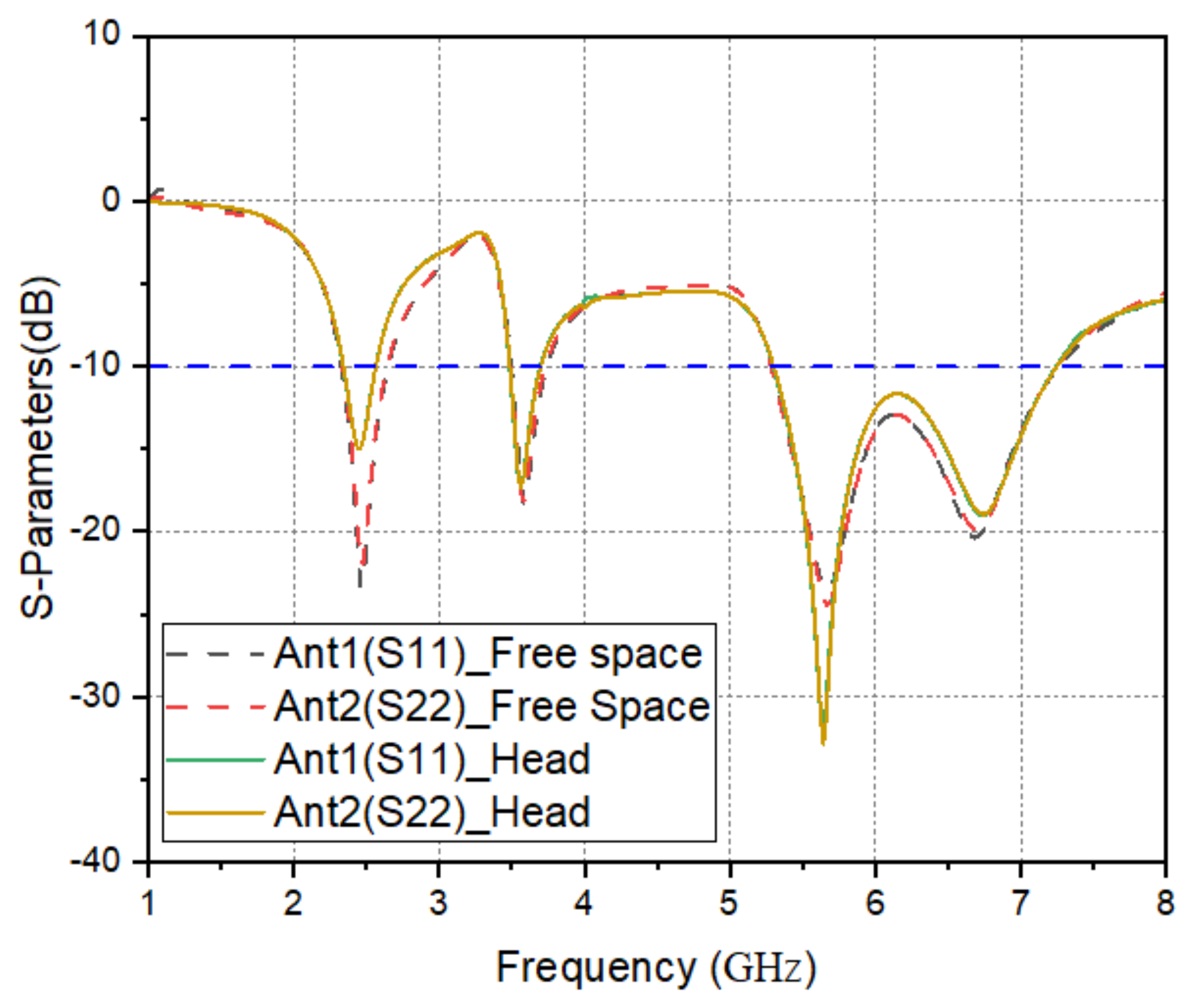
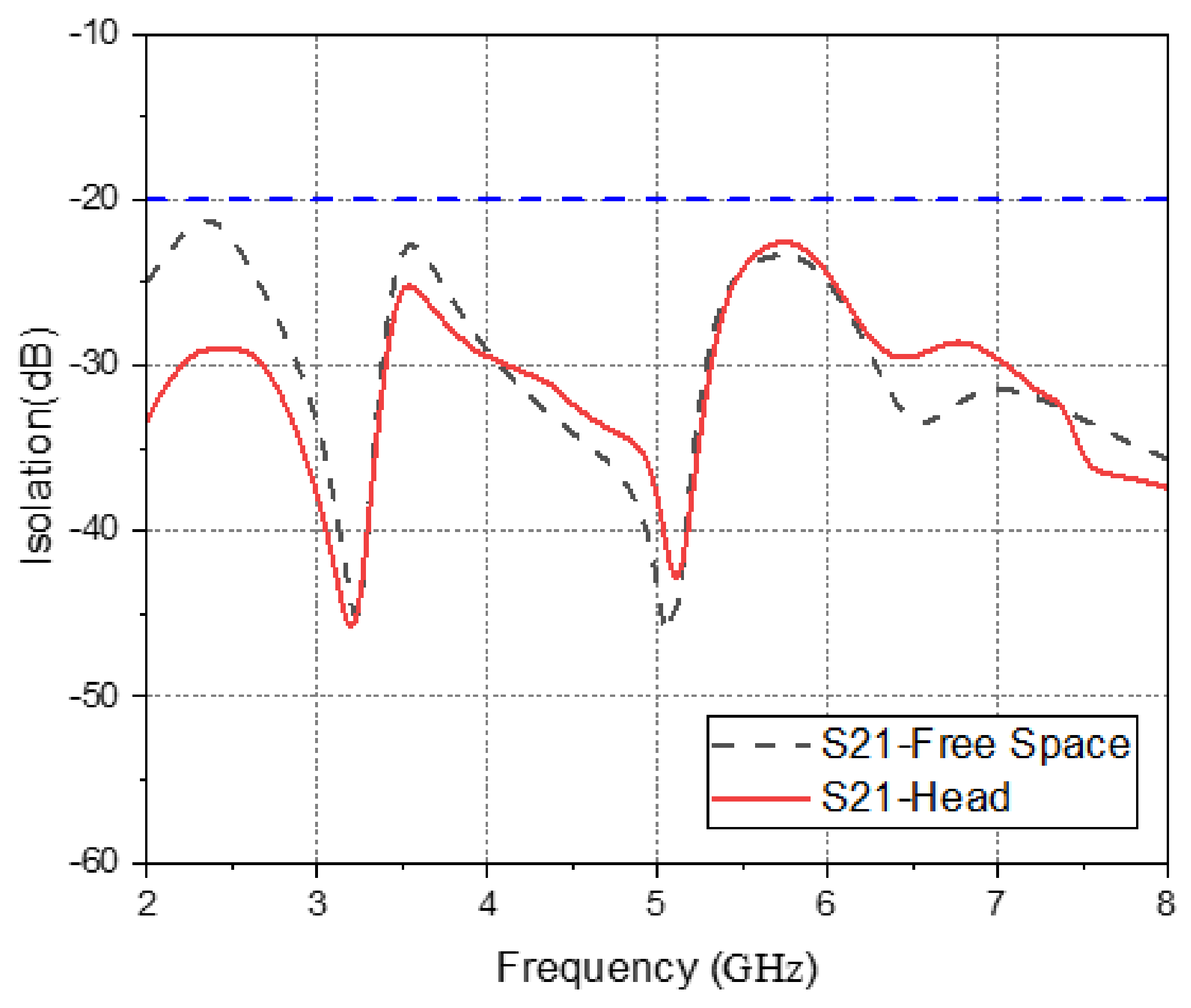
From Figure 27, the medical mask is worn on the head, and Ant. 1 and Ant. 2 are arranged on the left and right sides of the frame. The horizontal projection of Ant. 1 and Ant. 2 towards the head is about the position of the forehead. The distance between the front edge of the frame and the rear side is about 20 mm. Figure 28 shows that the reflection coefficients of simulated Ant. 1 and Ant. 2 in free space are similar to those when worn on the head. Figure 29 shows the comparison of the isolation between the simulated free-space Ant. 1 and Ant. 2 and the Ant. 1 and Ant. 2 worn on the head. The isolation between wearing on the head and in open space is lower than −20 dB.
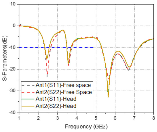
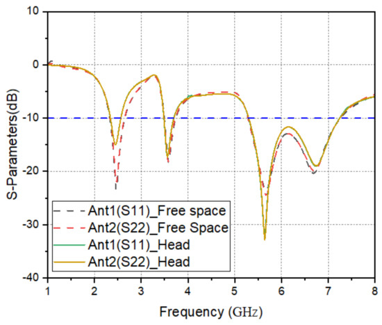
Figure 28.
Simulated reflection coefficients of Ant. 1 and Ant. 2 in free space and when worn on the head.
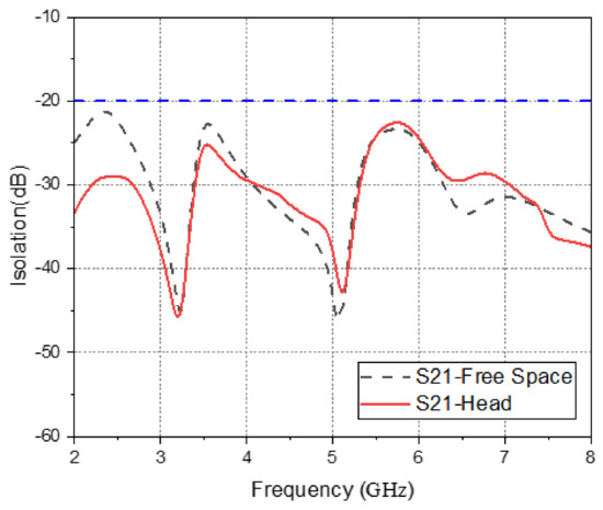
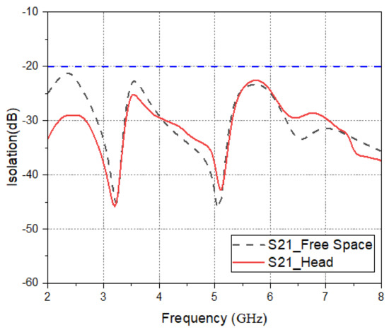
Figure 29.
Isolation for simulated Ant. 1 and Ant. 2 in free space and when worn on the head.
From Figure 27, Ant. 3 and Ant. 4 are arranged at the curved positions on the left and right sides of the shield, and Ant. 3 and Ant. 4 are projected horizontally to the head about the position of the eyebrows. Since the shield is mounted on the front edge of the frame, the distance between the shield and the human head is also about 20 mm. Figure 30 shows that the reflection coefficients of the simulated Ant. 3 and Ant. 4 in free space are similar to those worn on the head. Figure 31 shows the comparison of the isolation between the simulated free-space Ant. 3 and Ant. 4 and the Ant. 3 and Ant. 4 worn on the head. The isolation between wearing on the head and in open space is lower than −20 dB.
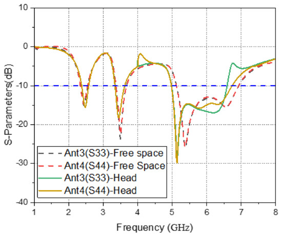
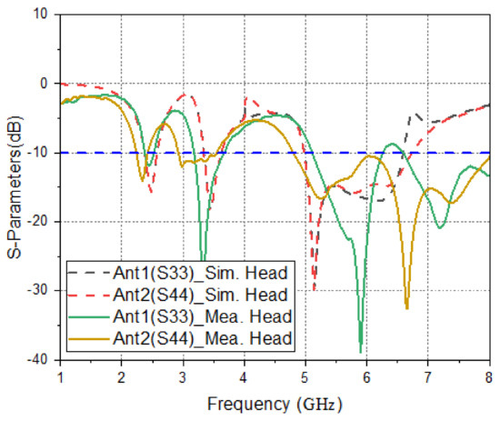
Figure 30.
Simulated reflection coefficients of Ant. 3 and Ant. 4 in free space and when worn on the head.
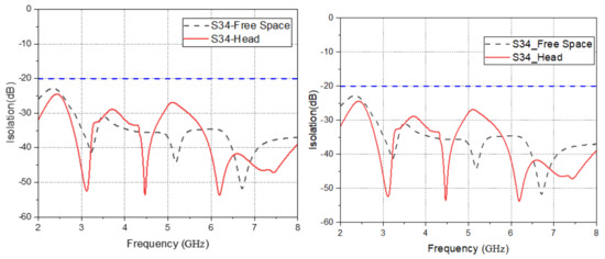
Figure 31.
Isolation for simulated Ant. 3 and Ant. 4 in free space and when worn on the head.
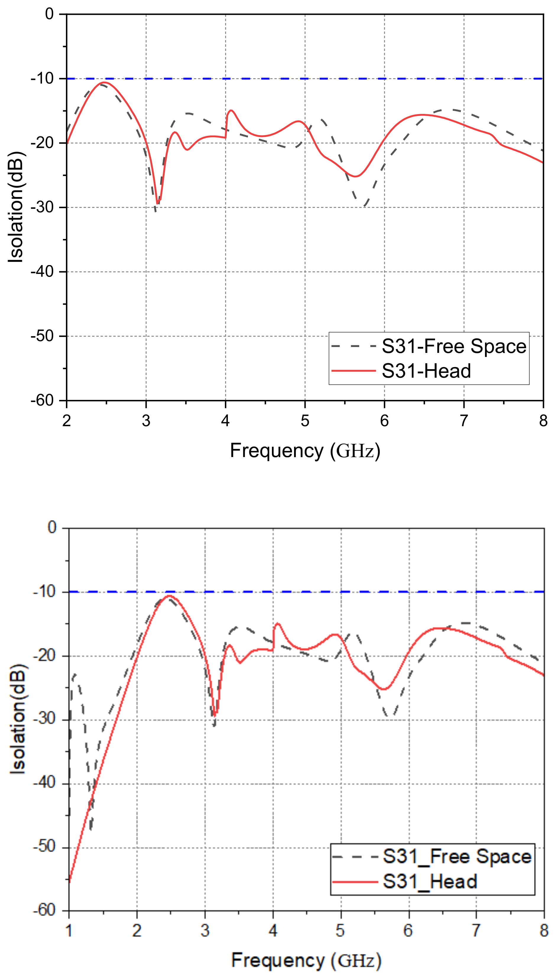
Figure 32 shows that the comparison of the isolation between the simulated free-space Ant. 1 and Ant. 4 and the isolation degree of the Ant. 1 and Ant. 4 worn on the head is lower than −20 dB. Figure 33 simulates the comparison of the isolation between the free-space Ant. 1 and Ant. 3 and when they are worn on the head. The isolation between Ant. 1 and Ant. 3, when worn on the head and in open space, is lower than −10 dB. The reason why the isolation between Ant. 1 and Ant. 3 is lower than the isolation between the other antennas is that Ant. 1 and Ant. 3 are located at relatively close positions as mentioned above.
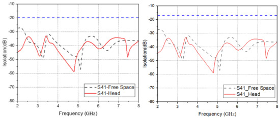
Figure 32.
The free space of the simulated Ant. 1 and Ant. 4 and the isolation degree worn on the head.

Figure 33.
The isolation degree of the simulated free-space Ant. 1 and Ant. 3 and when worn on the head.
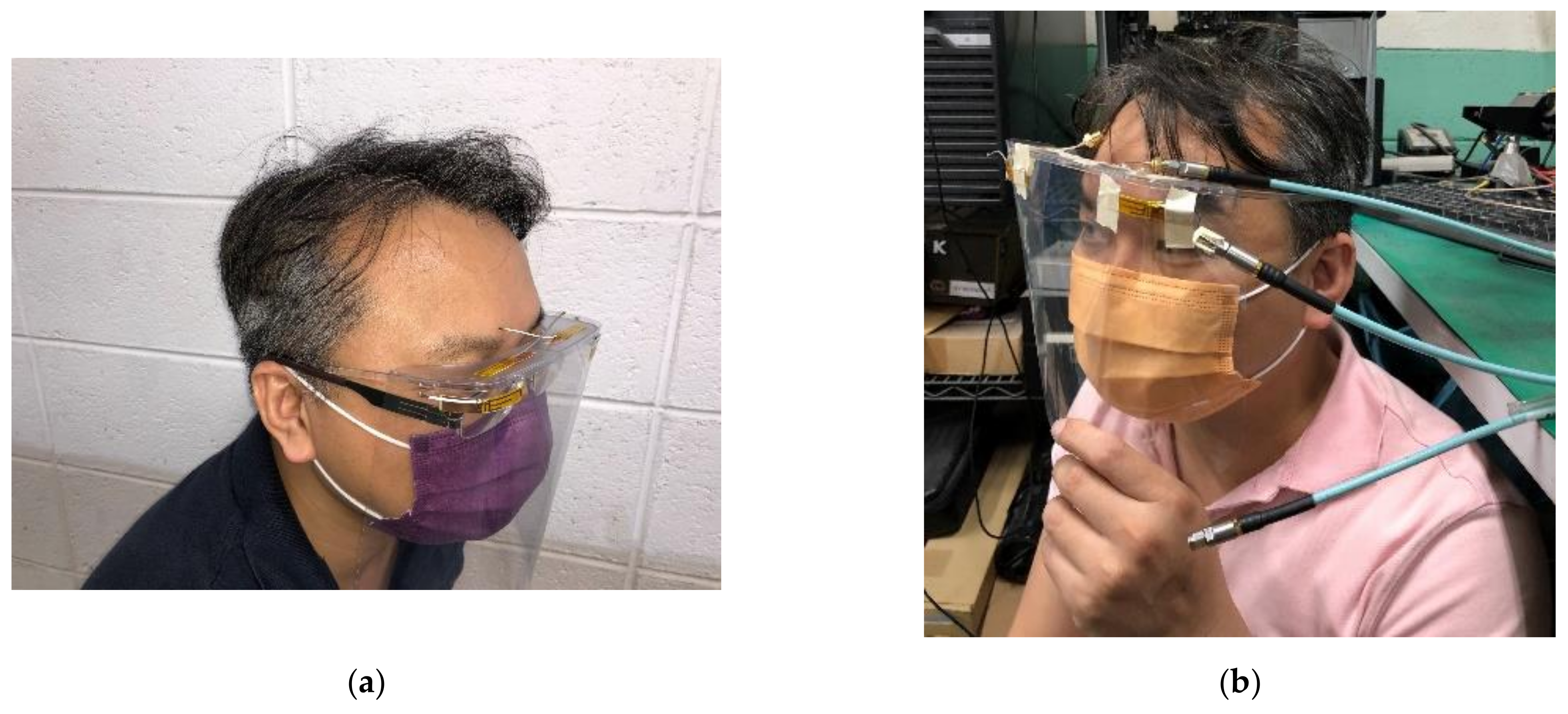
4.3. Simulation and Measurement Analysis of Wearing on Head
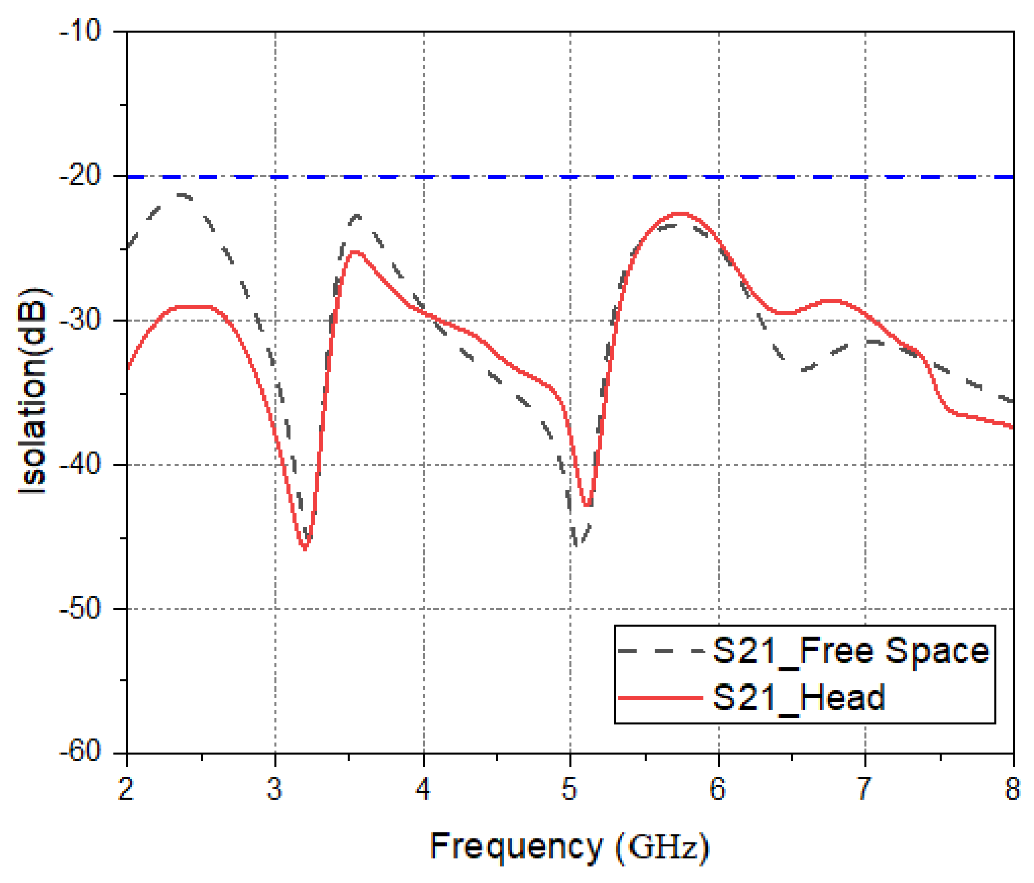
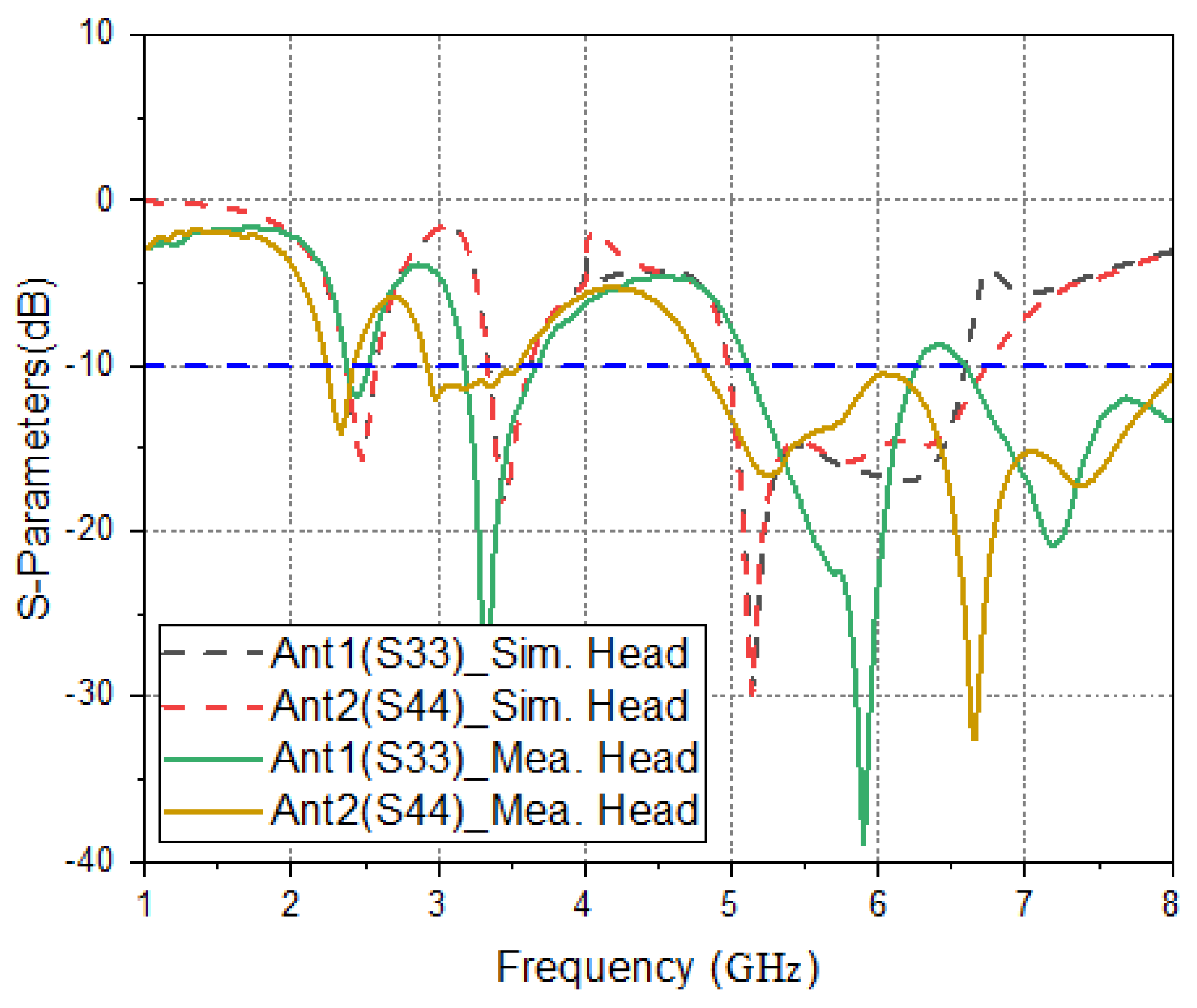
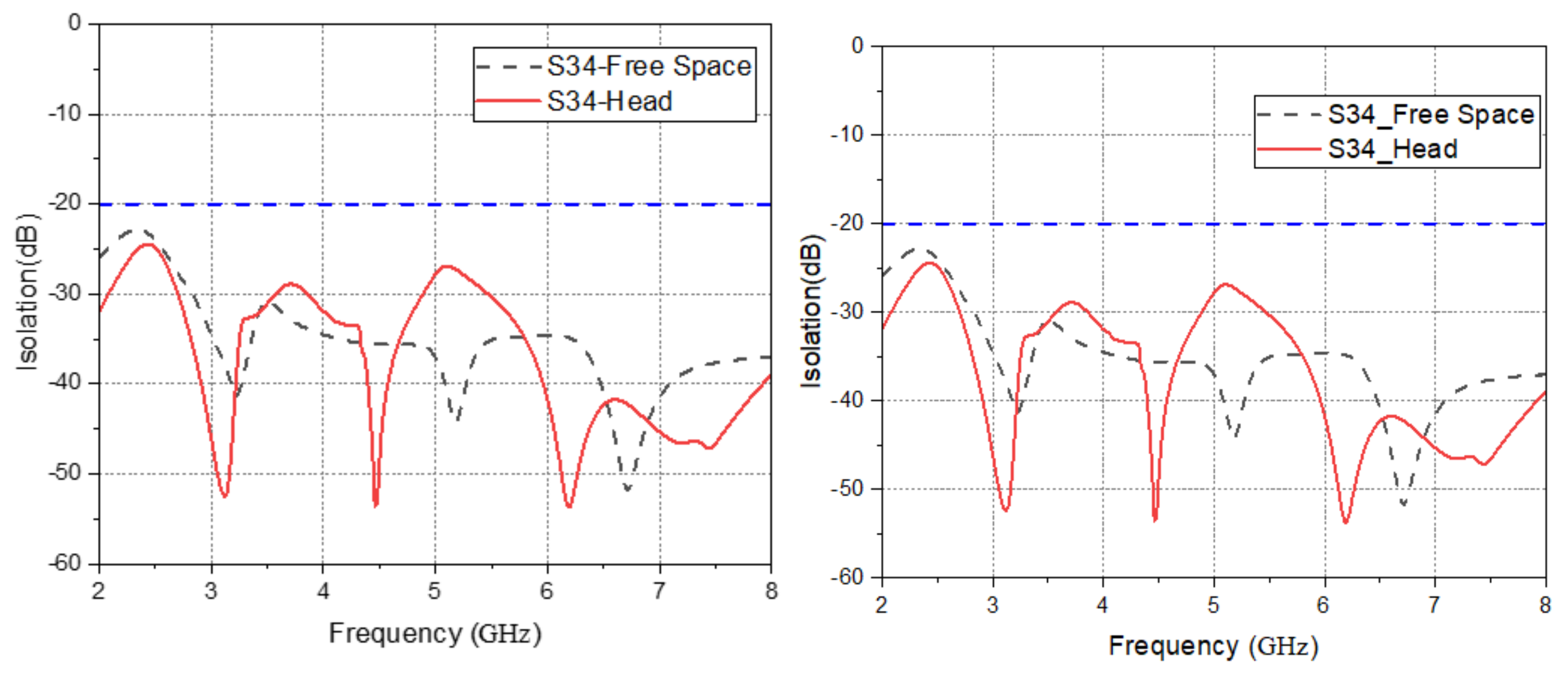
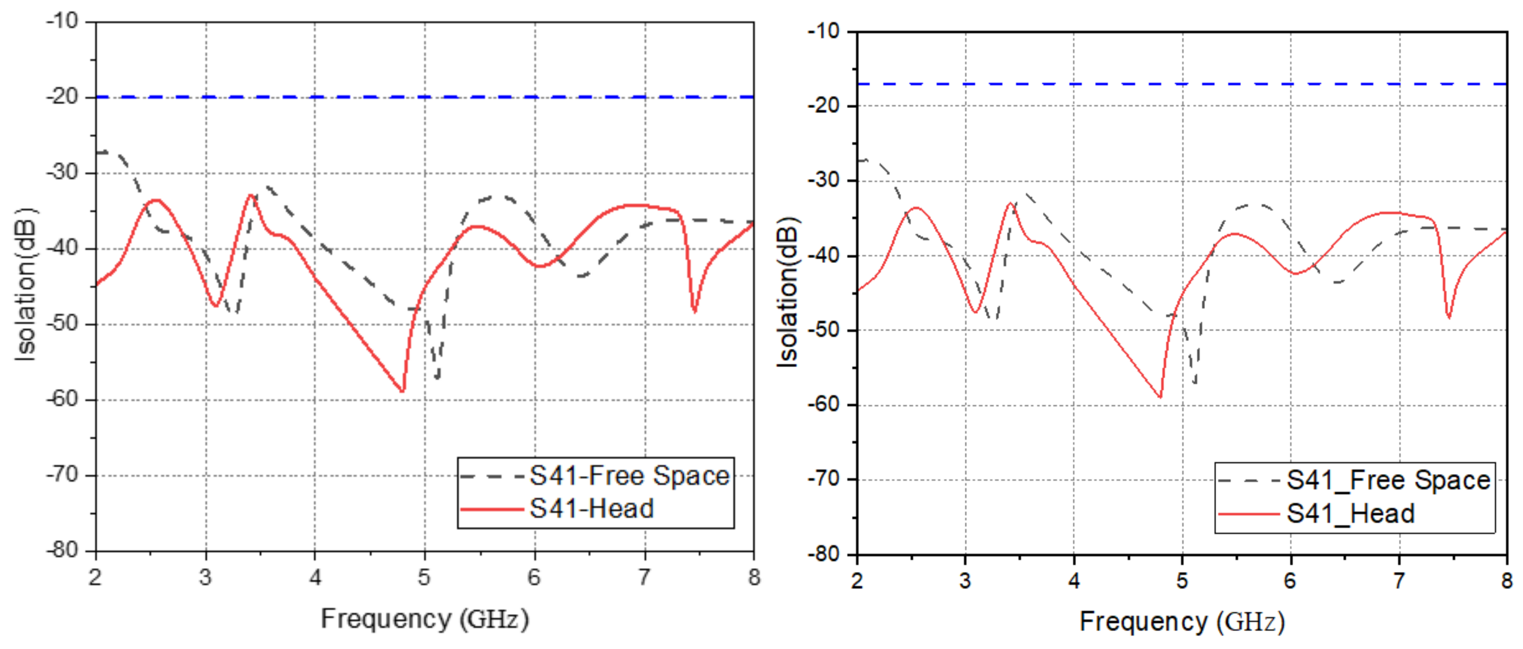
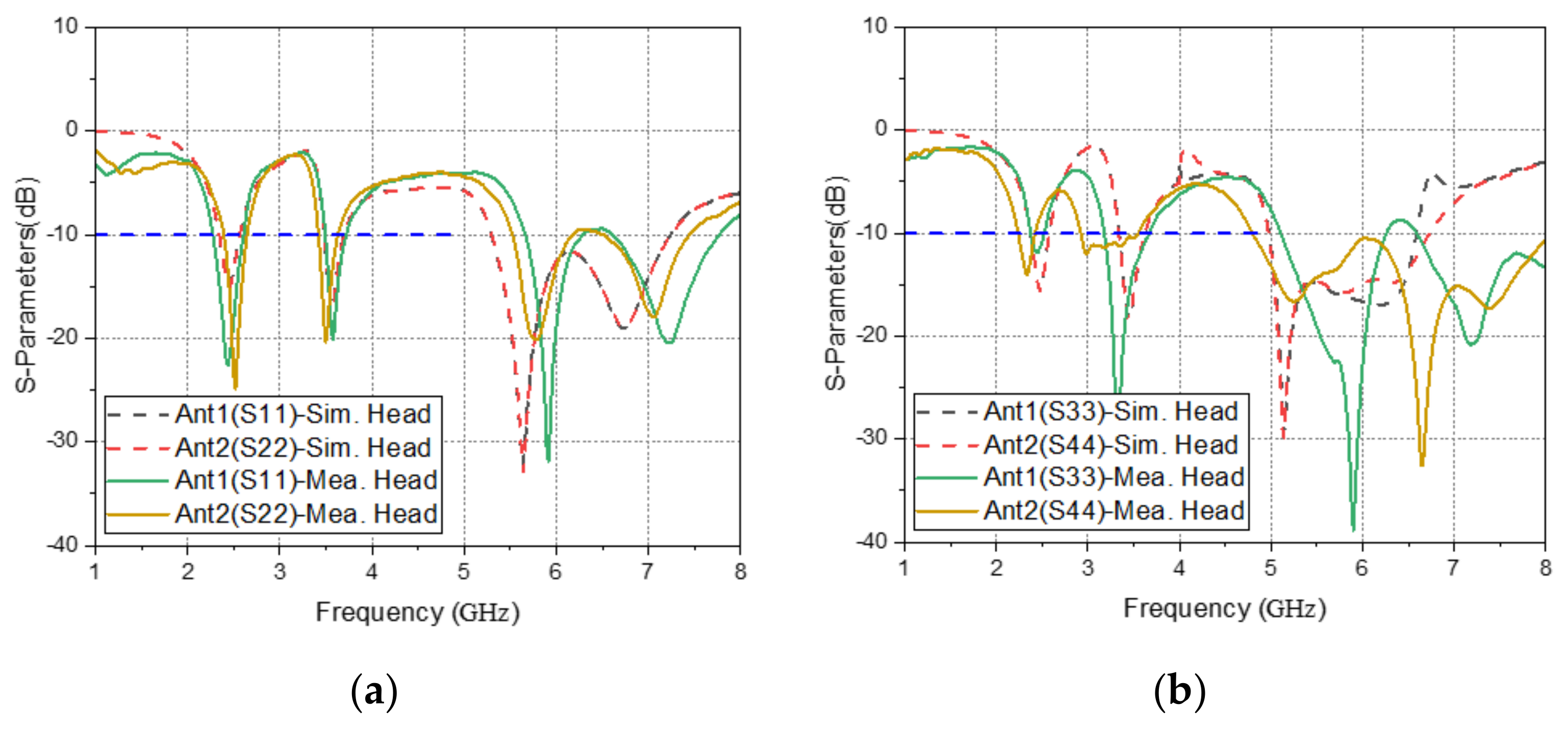
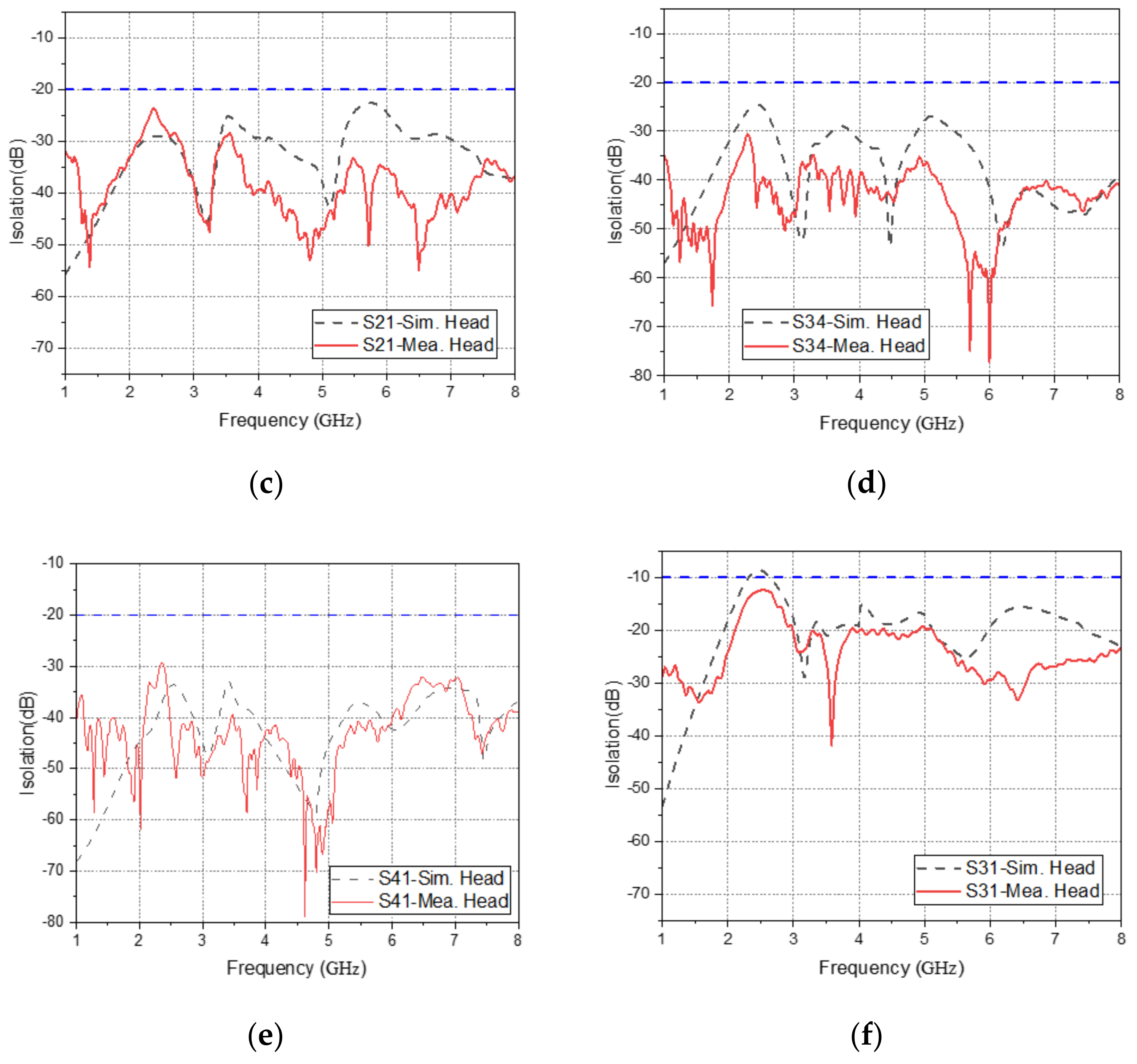
To further understand the comparison of the medical mask on the human head and the simulation, Figure 34 is a photo of the medical mask on the human head and the actual measurement. It can be seen from Figure 35 that the simulated and measured resonant frequency changes of Ant. 1 and Ant. 2 are quite similar. It can also be seen that the simulated and measured resonant frequencies of Ant. 3 and Ant. 4 are quite similar at low frequencies. However, the resonant frequencies at high frequencies varies slightly, but there are still similar resonant frequencies. Ant. 1 and Ant. 2, Ant. 3 and Ant. 4, and Ant. 1 and Ant. 4 have the same isolation degree between each antenna. Because they are far apart from each other, the isolation degree can be lower than −20 dB. Ant. 1 and Ant. 3 are adjacent to each other, and the isolation is lower than −10 dB. This indicates that the effective working frequency bands of the antennas are all as expected, and the isolation meets the basic conditions of the MIMO antenna system.

Figure 34.
(a) Photo of the medical mask on the human head, (b) photo of the medical mask on the human head.
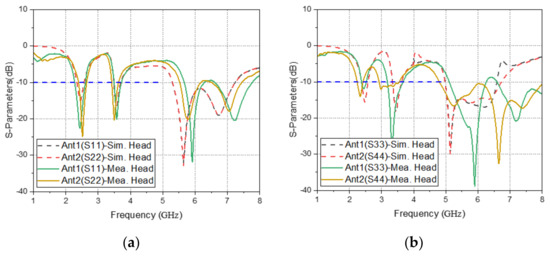
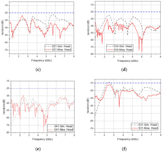
Figure 35.
(a) Simulated and measured reflection coefficients of Ant. 1 and Ant. 2 worn on the head, (b) simulated and measured reflection coefficients of Ant. 3 and Ant. 4 worn on the head, (c) simulated and measured isolation of Ant. 1 and Ant. 2 worn on the head, the (d) simulated and measured isolation of Ant. 3 and Ant. 4 worn on the head, (e) simulated and measured isolation pf Ant. 1 and 4 worn on the head, and (f) the simulated and measured isolation of Ant. 1 and Ant. 3 worn on the head.
4.4. Specific Absorption Rate (SAR) Simulation Aanalysis
Wearable devices are electronic products that are used in close proximity to the human body. They transmit wireless communication through antennas. Therefore, electromagnetic radiation will be generated during the transmission process. All countries have SAR specifications, which are mainly used to limit the damage caused by electronic products to the human body, including absorption of electromagnetic radiation. Its regulatory limits according to the US FCC are 1 g SAR 1.6 W/kg, and according to the European CE, 10 g SAR 2 W/kg for bulk. The calculation method of SAR is the radiation power energy absorbed by a unit volume in a specific time, as shown in the following equations [22]:
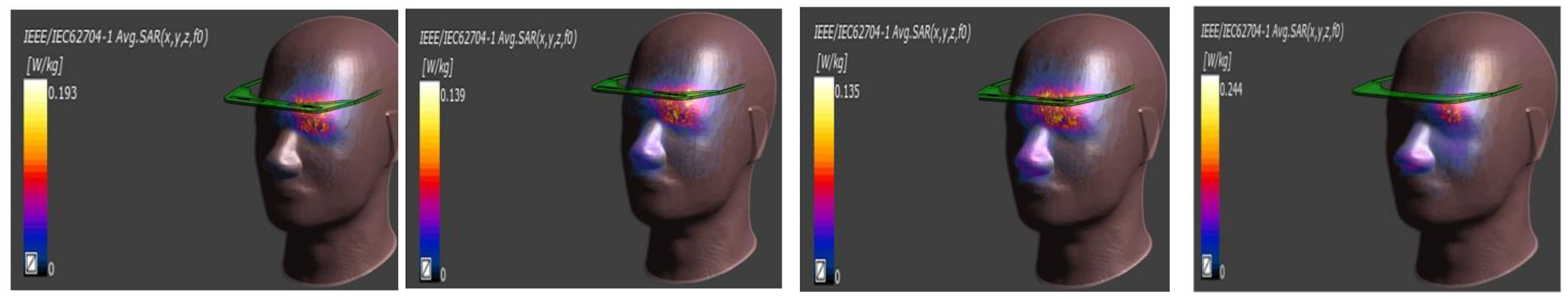
The structure of the antenna system proposed in this paper is left- and right-symmetrical, so only the SAR values of Ant. 1 and Ant. 3 are simulated. The SAR simulation software uses Sim4Life to operate, as shown in Figure 36 and Figure 37 below. When Ant. 1 is 20 mm away from the head, and the input power from the feed point is 0.1 W (20 dBm), the frequencies are 2.4 GHz, 3.5 GHz, 5.5 GHz, and 6.8 GHz to calculate the value of 1 g SAR and 10 g SAR. The 1 g SAR and 10 g SAR of Ant. 1 at 2.4 GHz, 3.5 GHz, 5.5 GHz, and 6.8 GHz are shown in the Table 2, and all SAR values are lower than the regulatory limit. Figure 36 and Figure 37 hides the shield to highlight the SAR distribution state of Ant. 1.
Figure 36.
1 g SAR Simulation Results for Ant. 1 at 2.4 GHz, 3.5 GHz, 5.5 GHz, and 6.8 GHz.
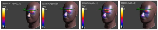
Figure 37.
10 g SAR simulation results of Ant. 1 at 2.4 GHz, 3.5 GHz, 5.5 GHz, and 6.8 GHz.
Table 2.
Simulated 1 g SAR and 10 g SAR for Ant. 1 and Ant. 3.
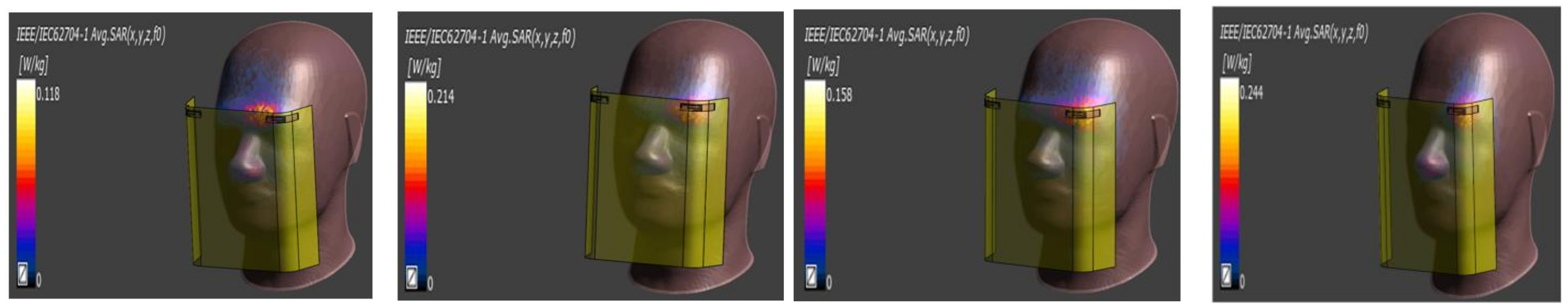
As shown in Figure 38 and Figure 39 below, when Ant. 3 is 20 mm away from the head, the input power from the feed point is 0.1 W (20 dBm), and the frequencies are 2.4 GHz, 3.5 GHz, 5.5 GHz, and 6.8 GHz to calculate 1 g SAR and 10 g SAR values. The 1 g SAR and 10 g SAR of Ant. 3 at 2.4 GHz, 3.5 GHz, 5.5 GHz, and 6.8 GHz are shown in the Table 2, and all SAR values are lower than the regulatory limit. Figure 38 and Figure 39 hide the frame to highlight the SAR distribution state of Ant. 3.
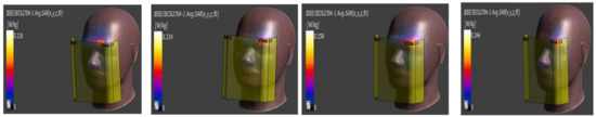
Figure 38.
The 10 g SAR simulation results of Ant. 3 at 2.4 GHz, 3.5 GHz, 5.5 GHz, and 6.8 GHz.
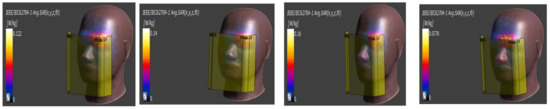
Figure 39.
10 g SAR Simulation Results for Ant. 3 at 2.4 GHz, 3.5 GHz, 5.5 GHz, and 6.8 GHz.
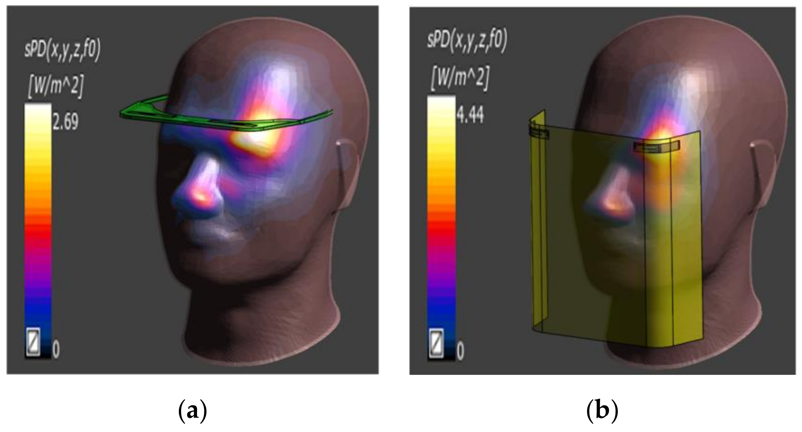
According to the FCC regulatory test requirements, when the wearable device supports frequency bands above 6 GHz, additional power density needs to be measured. The test frequency is selected as the frequency point with the worst SAR value, and the PD regulatory limit is 10 W/m2. The formula is as follows [23]:
Based on the above reasons, the author simulated the test power density (PD) of Ant. 1 and Ant. 3. Figure 40a below shows that when the input power of Ant. 1 from the feed point is 0.1 W (20 dBm), the frequency is 6.8 GHz to calculate the PD value. According to the simulation results, the PD of Ant. 1 at 6.8 GHz is 2.69 W/m2, which is lower than the regulatory limit of 10 W/m2. Figure 40b shows that when the input power of Ant. 3 from the feed point is 0.1 W (20 dBm), the frequency is 6.8 GHz to calculate the PD value. According to the simulation results, the PD of Ant. 3 at 6.8 GHz is 2.69 W/m2, which is lower than the regulatory limit of 10 W/m2.
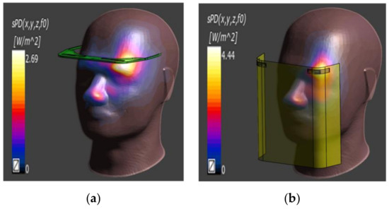
Figure 40.
PD simulation results at 6.8 GHz: (a) Ant. 1, (b) Ant. 3.
4.5. Performance Comparison with Other Antennas
Table 3 is a comparison table between the proposed antenna and other antenna studies. The sizes of the antennas in references [12,14,15,16,17,18,19,20,21] are larger than that of the antenna system in this paper. Among them, the references [12,13,14,15,19,20] only support two working frequency bands. Although the references [17,18,21] have more frequency bands, the efficiency of the antenna is not good, and the bandwidth is also insufficient. Only [18,20] have MIMO functions, but [18] has a large antenna size. Reference [20] does not support the frequency band of 5G FR1. In addition, all the antennas of [12,13,14,15,16,17,18,19,20,21] are designed on a single material, while Ant. 1 and Ant. 2 in this paper are designed on FR4 and PC, and Ant. 3 and Ant. 4 are designed on FR4 and PET. Furthermore, the current references do not have the antenna design applied to 5G FR1 and Wi-Fi 7. This paper proposes a medical mask with a wide operating bandwidth, high antenna efficiency, high antenna gain, and 2 x 2 MIMO support, and applies it to 5G Antenna design for FR1 and Wi-Fi 7.
Table 3.
Antenna Comparison Table.
The further differences between this paper and other literatures are further explained here. The antenna in this paper is arranged on a medical mask, which is an unprecedented design. The different working frequency bands for indoor and outdoor applications are designed with an extremely small antenna size, which improves upon the problem that traditional antenna designs are not suitable for miniaturization. Furthermore, this paper designs the antenna in the plane and curved positions at the same time, which has not been found in the literature. In particular, the two antenna types can be adapted to different materials and different geometrical positions with only minor modifications, which shows the superiority of the design as documented in this paper.
5. Conclusions
This paper proposes a method to enable a medical mask to use an simple designed antenna system for 5G FR1 and Wi-Fi 7 communications. Moreover, the antenna system is set on composite materials, and the antenna is designed in different composite materials and placed in a curved position, and the geometry of the antenna does not change much, which proves that the antenna system has high robustness and is very suitable for different applications. Material combinations indicate that the antenna system can be suitable for use in wearable devices. In the end, this paper also successfully produced a solid antenna, and the actual measurement results show that the efficiency and gain of the antenna are good, so the medical mask has a high probability of being used in the application scenarios of 5G FR1 and Wi-Fi 7 in the future.
This paper has proposed a medical mask that can be used indoors and outdoors to cope with the amount of medical data transmission that may increase in the future. If the antenna design of the 5G FR2-related working frequency band is further added to the medical mask, it may make the application of medical masks wider, and accelerate the realization of medical masks in actual medical services.
Author Contributions
Conceptualization, M.-A.C.; methodology, M.-A.C.; software, M.-A.C., M.-C.L. and C.-W.H.; validation, M.-C.L. and C.-W.H.; formal analysis, M.-A.C., M.-C.L. and C.-W.H.; investigation, M.-A.C.; resources, M.-A.C.; writing—original draft preparation, M.-A.C. and M.-C.L.; writing—review and editing, M.-A.C.; visualization, M.-A.C.; supervision, M.-A.C.; project administration, M.-A.C.; funding acquisition, M.-A.C. All authors have read and agreed to the published version of the manuscript.
Funding
This research received no external funding.
Conflicts of Interest
The authors declare no conflict of interest.
References
- Ometov, A.; Shubina, V.; Klus, L.; Skibińska, J.; Saafi, S.; Pascacio, P.; Flueratoru, L.; Gaibor, D.Q.; Chukhno, N.; Chukhno, O. A survey on wearable technology: History, state-of-the-art and current challenges. Comput. Netw. 2021, 193, 108074. [Google Scholar]
- Dachyar, M.; Zagloel, T.Y.M.; Saragih, L.R. Knowledge growth and development: Internet of things (IoT) research, 2006–2018. Heliyon 2019, 5, e02264. [Google Scholar] [PubMed] [Green Version]
- Ahsan, M.; Teay, S.H.; Sayem, A.S.M.; Albarbar, A. Smart Clothing Framework for Health Monitoring Applications. Signals 2022, 3, 113–145. [Google Scholar] [CrossRef]
- Paracha, K.N.; Rahim, S.K.A.; Soh, P.J.; Khalily, M. Wearable antennas: A review of materials, structures, and innovative features for autonomous communication and sensing. IEEE Access 2019, 7, 56694–56712. [Google Scholar] [CrossRef]
- Park, S.-M.; Kim, Y.-G. A Metaverse: Taxonomy, components, applications, and open challenges. IEEE Access 2022, 10, 4209–4251. [Google Scholar] [CrossRef]
- Ratcliff, J.; Supikov, A.; Alfaro, S.; Azuma, R. ThinVR: Heterogeneous microlens arrays for compact, 180 degree FOV VR near-eye displays. IEEE Trans. Vis. Comput. Graph. 2020, 26, 1981–1990. [Google Scholar] [CrossRef]
- Lavric, A.; Petrariu, A.I.; Mutescu, P.-M.; Coca, E.; Popa, V. Internet of Things Concept in the Context of the COVID-19 Pandemic: A Multi-Sensor Application Design. Sensors 2022, 22, 503. [Google Scholar] [CrossRef] [PubMed]
- Vavrinsky, E.; Zavodnik, T.; Debnar, T.; Cernaj, L.; Kozarik, J.; Micjan, M.; Nevrela, J.; Donoval, M.; Kopani, M.; Kosnacova, H. Research and Development of a COVID-19 Tracking System in Order to Implement Analytical Tools to Reduce the Infection Risk. Sensors 2022, 22, 526. [Google Scholar] [CrossRef] [PubMed]
- Siriwardhana, Y.; Gür, G.; Ylianttila, M.; Liyanage, M. The role of 5G for digital healthcare against COVID-19 pandemic: Opportunities and challenges. ICT Express 2021, 7, 244–252. [Google Scholar] [CrossRef]
- Ahad, A.; Tahir, M.; Aman Sheikh, M.; Ahmed, K.I.; Mughees, A.; Numani, A. Technologies Trend towards 5G Network for Smart Health-Care Using IoT: A Review. Sensors 2020, 20, 4047. [Google Scholar] [CrossRef]
- Sabban, A. Wearable circular polarized antennas for health care, 5G, energy harvesting, and IoT systems. Electronics 2022, 11, 427. [Google Scholar] [CrossRef]
- Smida, A.; Iqbal, A.; Alazemi, A.J.; Waly, M.I.; Ghayoula, R.; Kim, S. Wideband wearable antenna for biomedical telemetry applications. IEEE Access 2020, 8, 15687–15694. [Google Scholar] [CrossRef]
- Wang, Y.; Zhang, J.; Peng, F.; Wu, S. A glasses frame antenna for the applications in Internet of Things. IEEE Internet Things J. 2019, 6, 8911–8918. [Google Scholar] [CrossRef]
- Wong, K.-L.; Chang, H.-J.; Wang, C.-Y.; Wang, S.-Y. Very-low-profile grounded coplanar waveguide-fed dual-band WLAN slot antenna for on-body antenna application. IEEE Antennas Wirel. Propag. Lett. 2019, 19, 213–217. [Google Scholar] [CrossRef]
- Cil, E.; Dumanli, S. The design of a reconfigurable slot antenna printed on glass for wearable applications. IEEE Access 2020, 8, 95417–95423. [Google Scholar] [CrossRef]
- Xu, Y.; Qu, L.; Kim, H.; Liu, Y. S-shaped planar antenna with 45° tilted bidirectional radiation pattern for motorcycle helmets. Int. J. RF Microw. Comput.-Aided Eng. 2020, 30, e22420. [Google Scholar] [CrossRef]
- Wang, Y.-Y.; Ban, Y.-L.; Liu, Y. Sub-6 GHz 4G/5G conformal glasses antennas. IEEE Access 2019, 7, 182027–182036. [Google Scholar] [CrossRef]
- Fady, B.; Terhzaz, J.; Tribak, A.; Riouch, F. Integrated miniature multiband antenna designed for WWD and SAR assessment for human exposure. Int. J. Antennas Propag. 2021, 2021, 5548834. [Google Scholar] [CrossRef]
- Ellusamy, S.; Balasubramanian, R. Sub-6 GHz Quad-Band Reconfigurable Antenna for 5G Cognitive Radio Applications. Appl. Comput. Electromagn. Soc. J. 2021, 36, 1015–1025. [Google Scholar] [CrossRef]
- Wang, Y.-Y.; Ban, Y.-L.; Nie, Z. Dual-loop antenna for 4G LTE MIMO smart glasses applications. IEEE Antennas Wirel. Propag. Lett. 2019, 18, 1818–1822. [Google Scholar] [CrossRef]
- Elkorany, A.S.; Mousa, A.N.; Ahmad, S.; Saleeb, D.A.; Ghaffar, A.; Soruri, M.; Dalarsson, M.; Alibakhshikenari, M.; Limiti, E. Implementation of a Miniaturized Planar Tri-Band Microstrip Patch Antenna for Wireless Sensors in Mobile Applications. Sensors 2022, 22, 667. [Google Scholar] [CrossRef] [PubMed]
- Jiang, H.; You, L.; Wang, W.; Gao, X. Multiuser MIMO uplink transmission with electromagnetic exposure constraints: Spectral efficiency and energy efficiency tradeoff. IEEE Commun. Lett. 2022, 26, 1096–1100. [Google Scholar] [CrossRef]
- He, W.; Xu, B.; Yao, Y.; Colombi, D.; Ying, Z.; He, S. Implications of incident power density limits on power and EIRP levels of 5G millimeter-wave user equipment. IEEE Access 2020, 8, 148214–148225. [Google Scholar] [CrossRef]


Publisher’s Note: MDPI stays neutral with regard to jurisdictional claims in published maps and institutional affiliations. |
© 2022 by the authors. Licensee MDPI, Basel, Switzerland. This article is an open access article distributed under the terms and conditions of the Creative Commons Attribution (CC BY) license (https://creativecommons.org/licenses/by/4.0/).