Article

Design and Optimization of a Wireless Power Transfer System with a High Voltage Transfer Ratio

1
College of Electrical Engineering, Zhejiang University, Hangzhou 310027, China
2
Polytechnic Institute, Zhejiang University, Hangzhou 310015, China
3
Ningbo Jintai Rubber & Plastic Co., Ltd., Ningbo 315609, China
*
Author to whom correspondence should be addressed.
Electronics 2022, 11(14), 2115; https://doi.org/10.3390/electronics11142115
Submission received: 10 June 2022 / Revised: 3 July 2022 / Accepted: 4 July 2022 / Published: 6 July 2022
(This article belongs to the Section Power Electronics)

Abstract

:
With the development of the logistics industry, low-voltage systems, such as intelligent logistics vehicles, have also started to propose application scenarios for wireless power transfer systems. As most logistics vehicles use lithium batteries for energy supply, the wireless charging system has to adapt to the charging characteristic curve of lithium batteries. In this paper, a dual-transmitter single-receiver compound resonant compensation topology with a high voltage ratio is proposed, and a corresponding magnetic coupler is designed and optimized through finite element analysis, which guarantees adaptive output curves according to the working state. A 1 kW experimental platform is established to verify the theoretical analysis, which realizes a high voltage transformation ratio with 90.3% efficiency. Throughout the whole charging process, the output curve agrees with the charging profile of the lithium battery, which can greatly extend the service life of lithium batteries.

1. Introduction

In recent years, environmental pollution and the energy crisis have attracted increasing attention from the public. Meanwhile, the capacity and stability of batteries have been further developed. Compared with traditional fuel vehicles, electric vehicles have a higher energy efficiency. Considering this background, electric vehicles have found wider applications, which has resulted in the charging technology of electric vehicles becoming more and more important. The traditional charging scheme adopts the wired charging method with a fixed charging pile. However, because of the mechanical contact between the charging gun and the vehicle battery interface, there is a risk of electric shock or causing personal injury. Moreover, operating the charging device in extreme weather also poses a certain threat to the safety of staff. Compared with wired charging, wireless charging features no electrical contact, high safety, and high reliability, which has become a hot research topic.
In 2007, the MIT research group lit up a bulb 2 m away using magnetic resonant power transmission technology, and corresponding research work was published in Science [1]. J. R. Smith, at Washington University, utilized similar power transmission methodology, and the transferred power was increased to 60 W with 75% system efficiency. The research team also found out that, when the distance between two coils was too close, the “frequency splitting” phenomenon happened in the system. They also built a four-coil wireless power transfer system, and further put forward the concepts of over coupling, under coupling, and critical coupling. In terms of the control algorithm, the team proposed a frequency adjustment method, which was able to adjust system output in an adaptive way [2].
The Korean Academy of Science and Technology also conducted research on the WPT system with multiple groups of transmission coils, and analyzed the influence of system parameters on transmission efficiency [3,4]. Since 2007, the team has had three sets of complete experimental systems, which have been applied to buses, golf carts, and other vehicles. Their system realized 20 kW transmission power on a multi-functional sports vehicle, and the efficiency was around 71%
Zhejiang University has been investigating problems related to wireless power transfer since 2008, including the design of resonance compensation topology and optimization of the magnetic coupling coil [5,6,7,8]. The DC–DC efficiency of a 3.3 kW wireless power transfer system was above 95% at a transmission distance of 200 mm.
The Harbin Institute of Technology carried out a significant amount of research work on the structure and output characteristics of various resonant compensation topologies, the parameter design of radio energy transmission coupling mechanism, and the basic theory of resonant compensation topology. The team developed a 15 kW wireless charging system and proposed applications in underwater equipment, super-capacitors, etc. [9].
Until now, investigations on wireless power transfer technology have mainly focused on the design and optimization of the magnetic coupling structure [10,11,12,13,14], compensation topology [15,16,17,18,19,20,21,22,23], and control algorithm [24,25]. In addition to academic research, wireless power transfer technology has been commercialized. For instance, ZTE Co., Ltd., proposed high-power wireless charging products during the rapid development period of electric buses. At present, field tests of wireless charging have been carried out in many sites.
With the development of the logistics industry, intelligent logistics vehicles have also been widely used (Figure 1). Unlike electric vehicles, logistics vehicles mainly utilize low-voltage battery packs for power supply. The existing research on wireless power transfer mostly focuses on 300–400 V high-voltage systems, so the existing design scheme cannot be directly applied to low-voltage systems. Therefore, this paper focuses on the design and implementation of a wireless charging system for logistics vehicles with a high-voltage input and low-voltage output.
In the logistics vehicle scenario of this paper, a 48V low-voltage battery pack is utilized as the energy storage unit, the distance from the vehicle chassis to the ground is 10 cm, and the width of the coil dimension available for installation does not exceed 40 cm. It is required that the input voltage during charging is 300 V, the coupling coefficient of the whole system is between 0.2–0.3, the maximum power is 1 kW, and the efficiency is more than 90%.
The aim of this paper is to achieve a high voltage transformation ratio and energy efficiency optimization through the design of the compensation topology, coupling structure, and control scheme. This is achieved in the following steps:
(i)
The mathematical models of different compensation topologies are established and the variation of transformation ratio with circuit parameters is obtained, so as to calculate the output characteristics of different topologies and to determine the compound resonant topology network design used in this paper.
(ii)
The coupling structure is designed afterwards, and the coil and ferrite dimensions are optimized through finite element simulation to ensure that the coupling coefficient agrees with the design requirements.
(iii)
The closed-loop control scheme of the system is studied, and the parameters in the control system are optimized to ensure stable loop output of the WPT system.
(iv)
Finally, an experimental platform is established and the corresponding design parameters are verified through experimental results, including the voltage transformation ratio, output characteristics, etc.

2. Theoretical Analysis

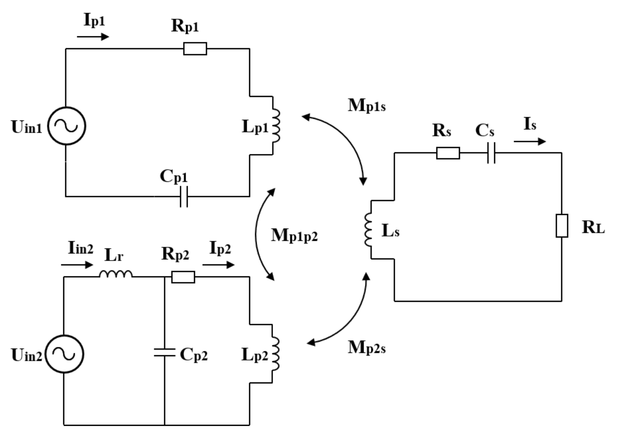
2.1. System Architecture

The system architecture of the wireless power transfer system with a high voltage transformation ratio is shown in Figure 2. The compound compensation topology network is composed of S-S and LCL-S, two resonant topologies. In practice, the load information is collected on the receiver controller, and is sent to the transmitter controller in a wireless way. After being processed by the transmitter controller, the adjusted PWM signal of the full bridge inverter switch is sent out, and the signal is amplified by the driving circuit to drive the MOSFET.

2.2. Circuit Analysis

The system architecture of the wireless power transfer system with a high voltage transformation ratio can be simplified as the equivalent circuit diagram, as shown in Figure 3.
The impedance of transmitter and receiver side can be written as follows:
Z p 1 = R p 1 + j ω L p 1 + 1 j ω C p 1 Z p 2 = j ω L r + R p 2 + j ω L p 2 1 + j ω C p 2 ( R p 2 + j ω L p 2 ) Z s = R L + R s + j ω L s + 1 j ω C s
In which Rp is the parasitic resistance of transmitter coil, Rs is the parasitic resistance of receiver coil, Cp is the resonant capacitance of transmitter, Cs is the resonant capacitance of receiver, Lp is the self-inductance of transmitter coil, Ls is the self-inductance of receiver coil, and RL is the load resistance.
The circuit loop equations are as follows:
Z p 1 I p 1 + j ω M p 1 p 2 I i n 2 j ω M p 1 s I s = U i n 1 j ω M p 1 p 2 I p 1 + Z p 2 I i n 2 j ω M p 2 s I s = U i n 2 j ω M p 1 s I p 1 j ω M p 1 s I i n 2 + Z s I s = 0
In which Uin is the input voltage of excitation source at transmitter side, Mpp is the mutual inductance of two transmitter coils, and Mps is the mutual inductance between transmitter and receiver coil.
Transform the loop equations into matrix form:
Z p 1 j ω M p 1 p 2 j ω M p 1 s j ω M p 1 p 2 Z p 2 j ω M p 2 s j ω M p 1 s j ω M p 2 s Z s I p 1 I i n 2 I s = U i n 1 U i n 2 0
By solving Equation (3), the current matrix I can be obtained, and the branch current of the LCL-S topology as well as the load current can be derived as follows:
I p 2 = 1 1 + j ω C p 2 ( R p 2 + j ω L p 2 ) I i n 2
I L = I s
According to the load current, the transferred power and system efficiency can be expressed as follows:
P 0 = I L 2 R L
η = P 0 Re [ U i n 1 I p 1 ] + Re [ U i n 2 I i n 2 ]
To sum up, the theoretical model of the dual-transmitter single-receiver wireless power transfer system composed of S-S and LCL-S compound resonant compensation topology is obtained.

2.3. Power and Efficiency Analysis

The key factor affecting the working state of the system is the load resistance of the system. The battery is the charging load in this case, which has a small external characteristic equivalent resistance during the initial constant current charging process. As the terminal voltage increases and the system switches to the constant voltage charging stage, the external equivalent resistance of the battery keeps increasing. This process is consistent with the designed system topology. When the system load changes, the respective equivalent resistances of the two branches of the primary side will change with the designed turning point, resulting in corresponding changes in the power distribution.

2.3.1. When the System Works in Constant-Current State

As discussed in previous literature [26], when the system works in a constant current state, the S-S compensation topology is in operation.
The transferred power and system efficiency is as follows:
P 0 = I L 2 R L = ω 2 M 2 U i n 2 R L [ R p ( R s + R L ) + ( ω M ) 2 ] 2
η = I L 2 R L I p U i n = ω 2 M 2 R L [ R p ( R s + R L ) + ( ω M ) 2 ] ( R s + R L )
As can be observed from Equations (8) and (9), the output power and system efficiency are affected by various factors, such as mutual inductance, frequency, coil internal resistance, load, and input voltage. As the internal equivalent resistance of the battery will gradually increase with the charging process, the battery is regarded as a dynamic load in the actual charging scene. The system working frequency is determined at 85 kHz and the input voltage is 300 V. The mutual inductance between the transmitter and receiver is 12 μH and the coil has an internal resistance of 0.1 Ω. The variation trend of the power and efficiency with load is drawn as shown in Figure 4.
As shown in Figure 4, the power and efficiency of the WPT system in the S-S topology are convex with the change of load resistance, i.e., they increase first and then decrease. However, it can be observed that the maximum power point and the maximum efficiency point do not coincide. The load resistance value corresponding to the maximum power point is slightly larger than that corresponding to the optimal efficiency point.
Find the partial derivative of Equation (8) to RL:
P 0 R L = ( ω M ) 2 U i n 2 [ R p R s + ( ω M ) 2 + R p R L ] [ R p R s + ( ω M ) 2 R p R L ] [ R p ( R s + R L ) + ( ω M ) 2 ] 4
Make the above formula equal to 0 and round off the negative root, and the load resistance corresponding to the maximum power point is as follows:
R L _ max _ P o ( s s ) = R s 1 + ( ω M ) 2 R p R s
where RL_max_Po(ss) is the equivalent load resistance value corresponding to the maximum output power of the system.
Similarly, find the partial derivative of RL from Equation (9):
η R L = ( ω M ) 2 [ R p R s 2 + R s ( ω M ) 2 R p R L 2 ] [ R p ( R s + R L ) + ( ω M ) 2 ] 4
Make the above formula equal to 0 and round off the negative root, and the load resistance corresponding to the maximum efficiency point is as follows:
R L _ max _ η ( s s ) = R s 1 + ( ω M ) 2 R p R s
where RL_max_η(ss) is the equivalent load resistance value corresponding to the maximum efficiency of the system.
Comparing Equations (11) and (13), it can be seen that the maximum power point is always on the right side of the maximum efficiency point. Therefore, if we want to ensure maximum output power, it will inevitably result in a relatively low-efficiency state. In order to strike a balance between output power and efficiency, the value of load resistance should be restricted in the following range:
R L _ max _ η ( s s ) R L R L _ max _ P o ( s s )

2.3.2. When the System Works in Constant Voltage State

When the system works in a constant voltage state, LCL-S topology is in operation.
The output power and efficiency are as follows:
P 0 = I L 2 R L = ω 4 M 2 C p 2 U i n 2 R L ( R s + R L ) 2
η = I L 2 R L I i n U i n = ω 2 M 2 R L ( R s + R L ) 2 ( R p + ω 2 M 2 R s + R L )
As can be seen from Equations (9) and (16), the efficiency expressions for the LCL-S and S-S topology are identical. The system working frequency is 85 kHz, the mutual inductance is 12 μH, the input voltage is 300 V, and the internal resistance of the coil is 0.1 Ω. The variation of power and efficiency with load resistance is drawn as shown in Figure 5.
It can be seen that the output characteristics of the LCL-S topology and S-S topology have the same trend, that is, the output power and efficiency curves are convex and have a maximum value. The load resistance value corresponding to the maximum output power is slightly larger than the load resistance value corresponding to the maximum efficiency. The efficiency characteristics of the LCL-S topology and S-S topology are exactly the same.
Find the partial derivative of Equation (15) to RL:
P 0 R L = ω 4 M 2 C p 2 U i n 2 ( R s R L ) ( R s + R L ) 3
Make the above formula equal to 0 and round off the negative root, and the load resistance corresponding to the maximum power point is as follows:
R L _ max _ P o ( L C L ) = R s
The load resistance of maximum efficiency corresponding to LCL-S and S-S topology are identical, i.e.,
R L _ max _ η ( L C L ) = R s 1 + ( ω M ) 2 R p R s
Based on the analysis above, if we set the maximum output power point of LCL-S and S-S topology to be the same, we have:
( ω M ) 2 R p R s
When the system meets the above conditions, there will be no sudden change in the output power of the system when switching from constant current mode to constant voltage mode. As the system frequency is given, the main factor affecting the above condition is the mutual inductance of the coupling structure.

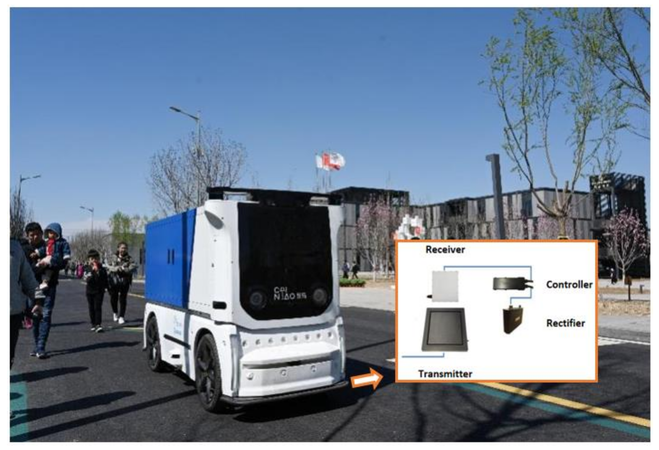
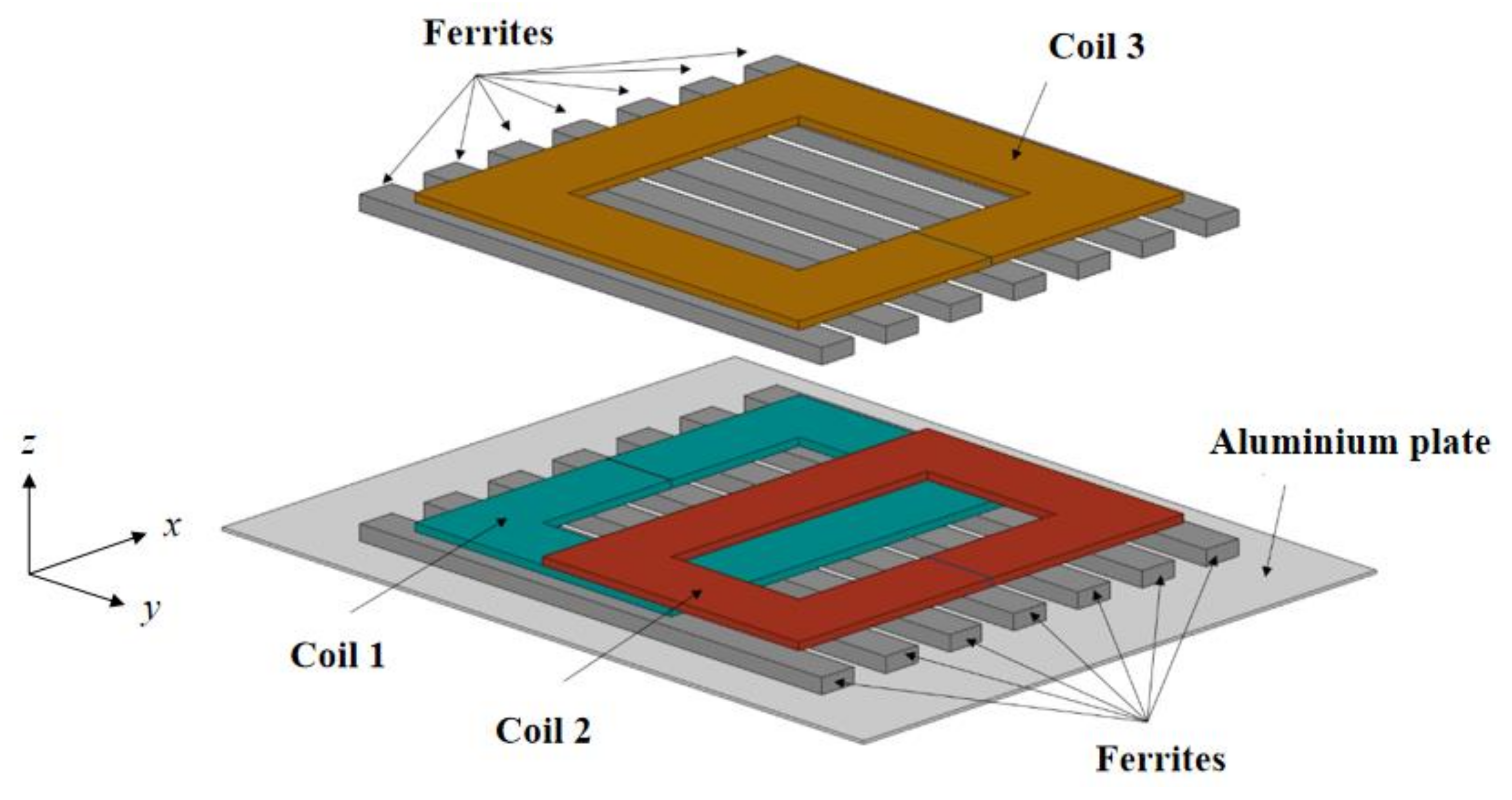
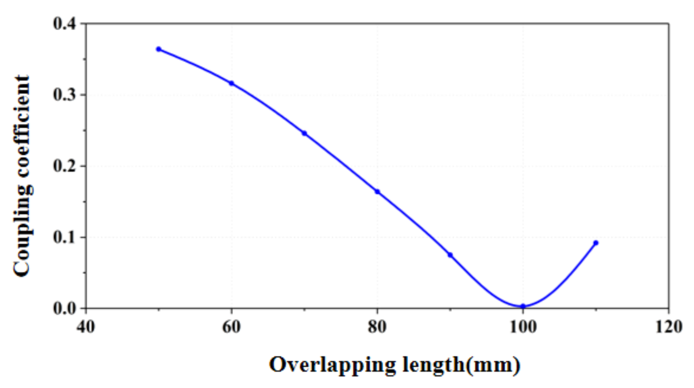
3. Design of Magnetic Coupling Structure

In order to increase the anti-displacement capability of the wireless power transfer system, as well as to align with the dual-transmitter, a single-receiver architecture is proposed in this paper. Two decoupled coils are utilized as the transmitter, and a rectangle coil is used as the receiver, as shown in Figure 6.
As for the two transmitter coils, if there is coupling between them, it will inevitably form a circulating current in the two coils, which will reduce the system efficiency and increase control complexity. However, if the two coils are overlapped, there is a position at which the magnetic field flows in the coil equals the magnetic field flows out, i.e., the two coils are decoupled, as shown in Figure 7.
The overlapping area of two coils can be determined through ANSYS simulation. As the space on the vehicle chassis available for coil installation is limited within 400 × 400 mm, the size of the aluminum plate for shielding should be larger than the coils. The dimension of the coil is preliminary determined to be 300 × 300 mm. Adjust the overlapping area of two coils and the variation of the coupling coefficient at different overlapping positions is shown in Figure 8.
The final design scheme of the coupling structure is shown in Figure 9. The dimensions of both the transmitter and receiver coils are 300 × 300 mm, the thickness of ferrite is 10 mm, the thickness of the aluminum plate is 2 mm, and the distance between the transmitter and receiver coils is 100 mm.
Finite element analysis is carried out in ANSYS to calculate the coupling coefficient between the transmitter and receiver coils, as shown in Figure 10. When misalignment happens in the y-axis direction, the coupling coefficient between coil 1 and coil 3 first decreases, while the coupling coefficient between coil 2 and coil 3 increases. When the misalignment further increases, k13 starts to increase and k12 begins to decrease, so the overall coupling coefficient k12 + k13 remains above 0.2.

4. Experimental Validation

In order to verify the transfer characteristics of the proposed magnetic coupling structure and compensation network, an experimental platform is established, as shown in Figure 11. The main power circuit is composed of a full-bridge inverter, coupling structure, compensation network, and rectifier bridge. The output variables are collected by the controller connected in parallel to the load. The proper topology will turn into theworking state according to the load resistance. The input voltage is 300 V, and the system working frequency is 85 kHz, the main parameters of the platform are shown in Table 1.

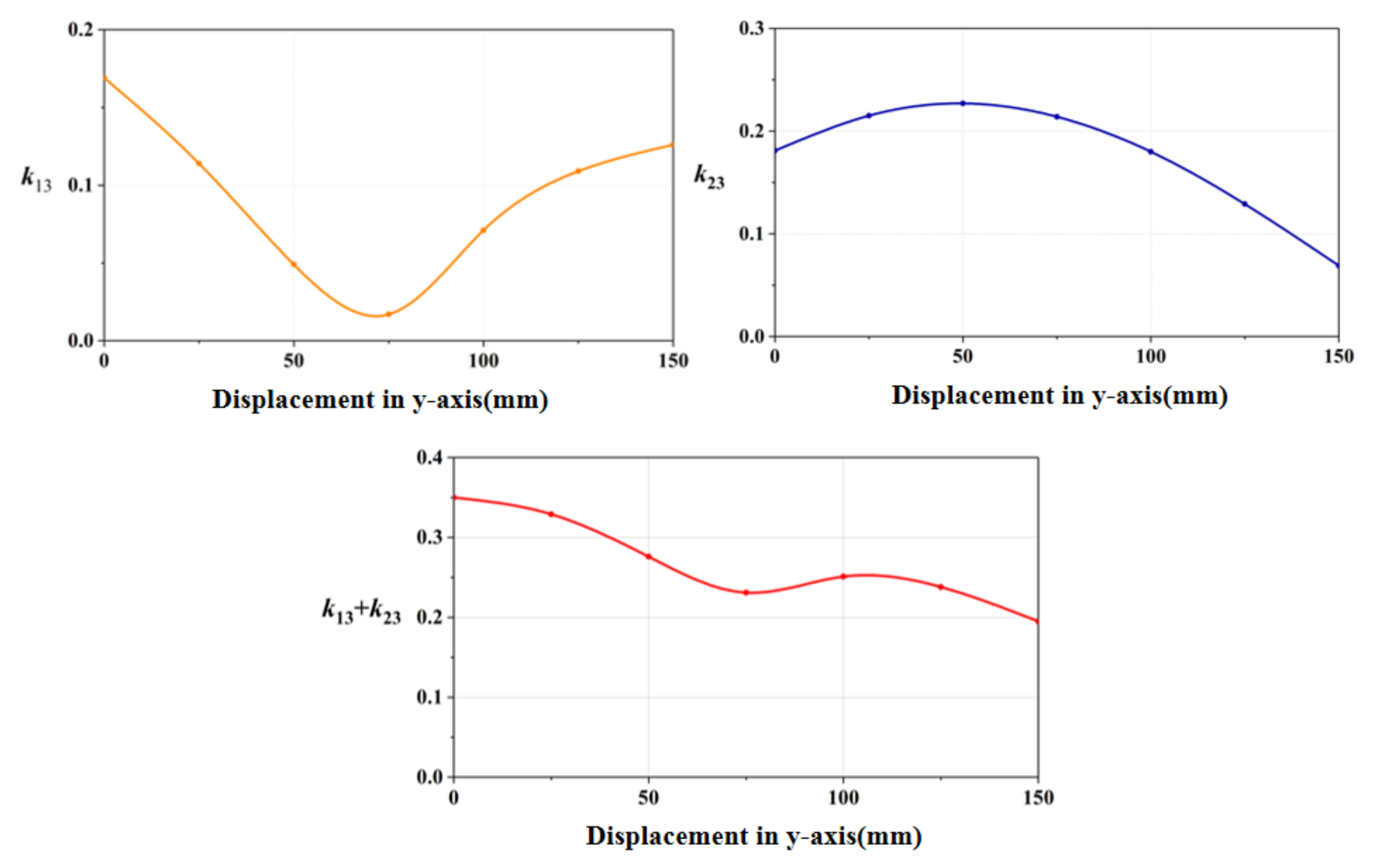
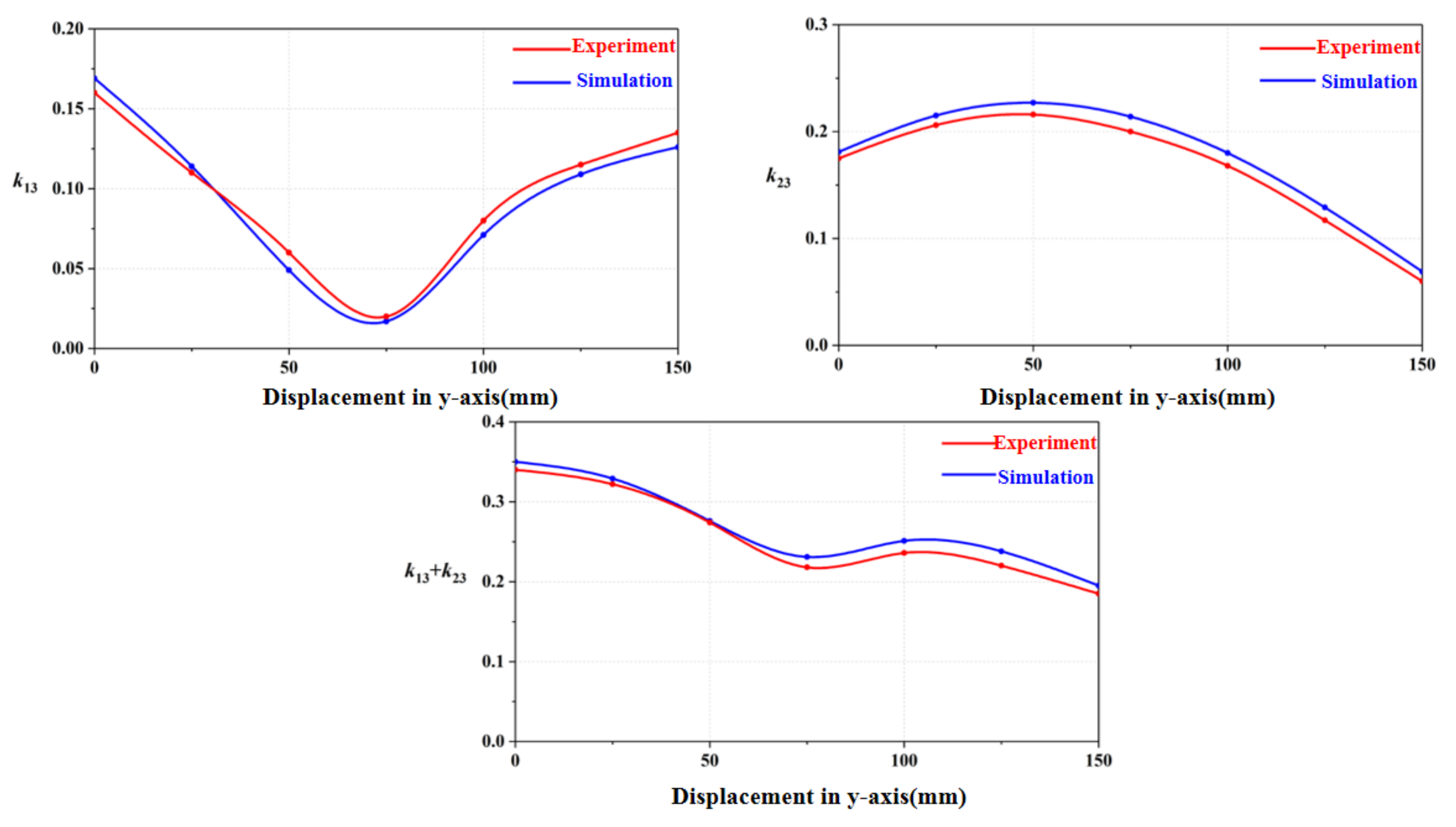
4.1. Verification on Coupling Mechanism

First, the designed coupling structure was tested in terms of the coupling coefficient variations with displacement. As shown in Figure 12, when displacement happens, the coupling coefficient k13 decreases first before increasing, while k12 first increases and then decreases, but the overall coupling coefficient roughly remains above 0.2. Comparing the simulation and experimental results, the coupling mechanism satisfies the expected requirements.

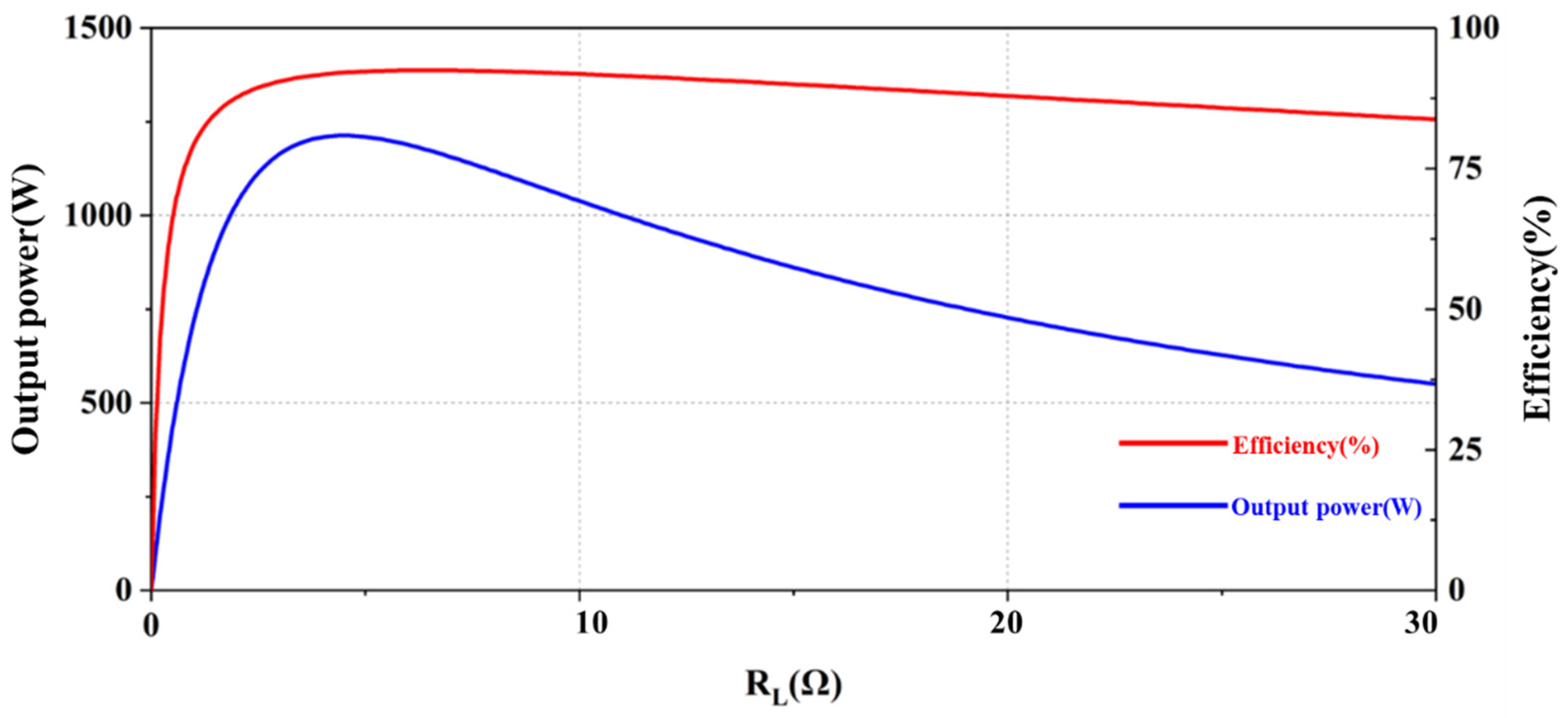
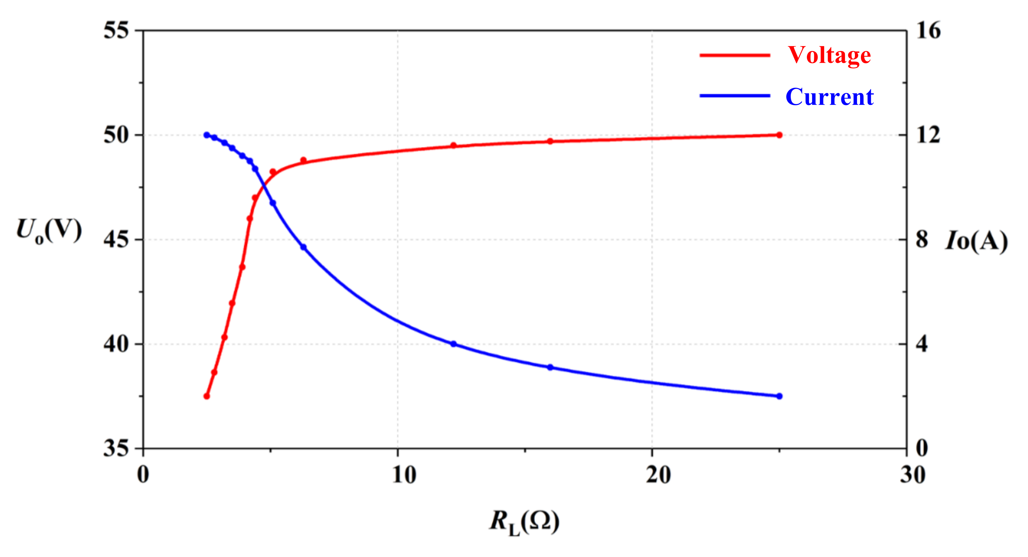
4.2. Verification on System Output Characteristics

The driving signal is tested when the main circuit is in operation, and the drive signal is shown in Figure 13. The dead time zone is set as 100 ns. As the full bridge inverter is composed of four switches, the driving module also outputs four driving signals, manipulated by two groups of complementary PWM signals sent by the primary controller. As shown in Figure 13, the output signals of the driving circuit are stable, and are not affected by the current fluctuation of the main power circuit, which meets the design requirements.
The output waveform of the full-bridge inverter is originally a square waveform, due to the resonant circuit, only the fundamental component in the form of a sine wave is retained. The full-bridge inverter voltage and coil current are shown in Figure 14.
In order to prevent large current flow in the whole circuit at the set-up point, the system proposed in this paper utilizes a soft start mode. The increasing speed of the load current is limited by the control program, so as to prevent overshoot from damaging the battery pack. The soft start process is shown in Figure 15. As can be seen from Figure 15, the load current rises to the preset value of the constant current stage after about 200 ms. The phase of the resonant current always lags slightly behind the square wave voltage, i.e., the full bridge inverter always works in the soft switching state.
In this paper, resistive load is used to simulate the charging process of the actual battery pack, and the charging process of the battery pack in different stages is characterized by different equivalent resistances. As shown in Figure 16, in the constant current stage, the variation in charging current is relatively small. When the load resistance rises to about 5 Ω (that is, the battery voltage reaches near the rated voltage in the actual charging process), the system switches to the constant voltage output mode. At this time, the load voltage remains basically unchanged, and the current drops rapidly until the end of the charging process. In the entire wireless charging process, the output voltage is stable and is maintained at around 48 V, the minimum output efficiency is 90.3%, and the maximum power is 1 kW.

4.3. Comparison with existing literature

The experimental results of our system are compared with the existing literature in terms of tolerance in offset, Tx coil failures, and output strategy switching, as shown in Table 2. Tolerance of Tx coil failures means whether the WPT system can still transmit power when one of the Tx coils cannot work normally. It worth noting that the comparison of allowable offset should be based on the size of the coil, as larger coils can tolerant a larger offset. The coupler designed in this paper can maintain a stable output at an offset of half its coil size. It can be concluded that the system proposed in this paper outperforms that found in the existing literature.

5. Conclusions

This paper designs and develops a wireless charging system for electric logistics vehicles. According to the characteristics of lithium batteries, a dual-transmitter single-receiver wireless power transmission system with S-S and LCL-S compound compensation topology is proposed, which realizes autonomous switching between the constant current and constant voltage output modes. By designing the circuit parameters of the S-S and LCL-S topologies separately, the entire WPT system can meet the output requirements of different charging stages. The staggered and stacked transmitting coil group can decouple the two coils and stabilize the coupling coefficient between the transmitter and receiver when offset occurs. The simulation and experimental results show that the system can stably conduct wireless power transmission when the input voltage is 300 V and the output voltage is 48 V, and the maximum transmission power is 1 kW. The highest system efficiency is 93.4% and the lowest system efficiency is 90.3%.

Author Contributions

Conceptualization, P.Y. and J.Z.; methodology, J.W. and P.Y.; hardware, Y.L. and J.G.; validation, J.W., A.Y. and Y.L.; writing—original draft preparation, J.W., P.Y. and Y.L.; writing—review and editing, S.H. All authors have read and agreed to the published version of the manuscript.

Funding

This research received no external funding.

Data Availability Statement

All of the data supporting the reported results have been included in this paper.

Conflicts of Interest

The authors declare no conflict of interest.

References

  1. Kurs, A.; Karalis, A.; Moffatt, R.; Joannopoulos, J.D.; Fisher, P.; Soljacic, M. Wireless power transfer via strongly coupled magnetic resonances. Science 2007, 317, 83–86. [Google Scholar] [CrossRef] [PubMed] [Green Version]
  2. Sample, A.P.; Meyer, D.T.; Smith, J.R. Analysis, Experimental Results, and Range Adaptation of Magnetically Coupled Resonators for Wireless Power Transfer. IEEE Trans. Ind. Electron. 2011, 58, 544–554. [Google Scholar] [CrossRef]
  3. Cheon, S.; Kim, Y.; Kang, S.; Lee, M.L.; Lee, J.; Zyung, T. Circuit-Model-Based Analysis of a Wireless Energy-Transfer System via Coupled Magnetic Resonances. IEEE Trans. Ind. Electron. 2013, 60, 360–371. [Google Scholar] [CrossRef]
  4. Ahn, D.; Hong, S. Effect of Coupling Between Multiple Transmitters or Multiple Receivers on Wireless Power Transfer. IEEE Trans. Ind. Electron. 2013, 60, 2602–2613. [Google Scholar] [CrossRef]
  5. Tang, Y.; Zhu, F.; Wang, Y.; Ma, H. Design and optimizations of solenoid magnetic structure for inductive power transfer in EV applications. In Proceedings of the IECON 2015-41st Annual Conference of the IEEE Industrial Electronics Society, Yokohama, Japan, 9–12 November 2015; IEEE: New York, NY, USA, 2015; pp. 001459–001464. [Google Scholar] [CrossRef]
  6. Tang, Y.; Chen, Y.; Madawala, U.K.; Thrimawithana, D.J.; Ma, H. A New Controller for Bi-directional Wireless Power Transfer Systems. IEEE Trans. Power Electron. 2017, 33, 9076–9087. [Google Scholar] [CrossRef]
  7. Tang, Y.; Zhu, F.; Ma, H. Efficiency Optimization with a Novel Magnetic-Circuit Model for Inductive Power Transfer in EVs. J. Power Electron. 2018, 18, 309–322. [Google Scholar]
  8. Tang, Y.; Ma, H. Dynamic Electrothermal Model of Paralleled IGBT Modules with Unbalanced Stray Parameters. IEEE Trans. Power Electron. 2017, 32, 1385–1399. [Google Scholar] [CrossRef]
  9. Li, Z.; Zhu, C.; Jiang, J.; Song, K.; Wei, G. A 3-kW Wireless Power Transfer System for Sightseeing Car Supercapacitor Charge. IEEE Trans. Power Electron. 2017, 32, 3301–3316. [Google Scholar] [CrossRef]
  10. Budhia, M.; Covic, G.A.; Boys, J.T. Design and Optimization of Circular Magnetic Structures for Lumped Inductive Power Transfer Systems. IEEE Trans. Power Electron. 2011, 26, 3096–3108. [Google Scholar] [CrossRef]
  11. Bosshard, R.; Iruretagoyena, U.; Kolar, J.W. Comprehensive Evaluation of Rectangular and Double-D Coil Geometry for 50 kW/85 kHz IPT System. IEEE J. Emerg. Sel. Top. Power Electron. 2016, 4, 1406–1415. [Google Scholar] [CrossRef]
  12. Budhia, M.; Covic, G.; Boys, J. A new IPT magnetic coupler for electric vehicle charging systems. In Proceedings of the IECON 2010—36th Annual Conference on IEEE Industrial Electronics Society, Glendale, AZ, USA, 7–10 November 2010; IEEE: New York, NY, USA, 2010; pp. 2487–2492. [Google Scholar]
  13. Zaheer, A.; Kacprzak, D.; Covic, G.A. A bipolar receiver pad in a lumped IPT system for electric vehicle charging applications. In Proceedings of the 2012 IEEE Energy Conversion Congress and Exposition (ECCE), Raleigh, NC, USA, 15–20 September 2012; IEEE: New York, NY, USA, 2012; pp. 283–290. [Google Scholar] [CrossRef]
  14. Futagami, D.; Sawahara, Y.; Ishizaki, T.; Awai, I. Study on high efficiency WPT underseas. In Proceedings of the 2015 IEEE Wireless Power Transfer Conference (WPTC), Boulder, CO, USA, 13–15 May 2015; pp. 1–4. [Google Scholar]
  15. Yoon, S.-H.; Kim, T.-H.; Yook, J.-G.; Yun, G.-H.; Lee, W.-Y. High Q-factor WPT system with negative impedance converter. In Proceedings of the 2017 IEEE Wireless Power Transfer Conference (WPTC), Taipei, China, 3–7 June 2017; pp. 1–4. [Google Scholar] [CrossRef]
  16. Takehiro, I.; Hiroyuki, O.; Toshiyuki, U.; Yoichi, H. Study of Magnetic and Electric Coupling for Contactless Power Transfer Using Equivalent Circuits. IEEE Trans. Ind. Appl. 2010, 130, 84–92. [Google Scholar]
  17. Koh, K.E.; Beh, T.C.; Imura, T.; Hori, Y. Impedance Matching and Power Division Using Impedance Inverter for Wireless Power Transfer via Magnetic Resonant Coupling. IEEE Trans. Ind. Appl. 2014, 50, 2061–2070. [Google Scholar] [CrossRef]
  18. Beh, T.C.; Kato, M.; Imura, T.; Oh, S.; Hori, Y. Automated Impedance Matching System for Robust Wireless Power Transfer via Magnetic Resonance Coupling. IEEE Trans. Ind. Electron. 2013, 60, 3689–3698. [Google Scholar] [CrossRef]
  19. Villa, J.L.; Sallan, J.; Osorio, J.F.S.; Llombart, A. High-Misalignment Tolerant Compensation Topology for ICPT Systems. IEEE Trans. Ind. Electron. 2012, 59, 945–951. [Google Scholar] [CrossRef]
  20. Hu, A.P. Selected Resonant Converters for IPT Power Supplies. Ph.D. Thesis, Department of Electrical and Computer Engineering, University of Auckland, Auckland, New Zealand, 2011. [Google Scholar]
  21. Zhang, W.; Mi, C.C. Compensation Topologies of High-Power Wireless Power Transfer Systems. IEEE Trans. Veh. Technol. 2016, 65, 4768–4778. [Google Scholar] [CrossRef]
  22. Li, S.; Li, W.; Deng, J.; Nguyen, T.D.; Mi, C.C. A Double-Sided LCC Compensation Network and Its Tuning Method for Wireless Power Transfer. IEEE Trans. Veh. Technol. 2015, 64, 2261–2273. [Google Scholar] [CrossRef]
  23. Lim, Y.; Tang, H.; Lim, S.; Park, J. An Adaptive Impedance-Matching Network Based on a Novel Capacitor Matrix for Wireless Power Transfer. IEEE Trans. Power Electron. 2014, 29, 4403–4413. [Google Scholar] [CrossRef]
  24. Berger, A.; Agostinelli, M.; Vesti, S.; Oliver, J.A.; Cobos, J.A.; Huemer, M. A Wireless Charging System Applying Phase-Shift and Amplitude Control to Maximize Efficiency and Extractable Power. IEEE Trans. Power Electron. 2015, 30, 6338–6348. [Google Scholar] [CrossRef]
  25. Matysik, J.T. The current and voltage phase shift regulation in resonant converters with integration control. IEEE Trans. Ind. Electron. 2007, 54, 1240–1242. [Google Scholar] [CrossRef]
  26. Zhou, J.; Yao, P.; Guo, K.; Cao, P.; Zhang, Y.; Ma, H. A Heterogeneous Inductive Power Transfer System for Electric Vehicles with Spontaneous Constant Current and Constant Voltage Output Features. Electronics 2020, 9, 1978. [Google Scholar] [CrossRef]
Figure 1. Electric logistics vehicle.
Electronics 11 02115 g001
Figure 2. System architecture for a wireless power transfer system with a high voltage transformation ratio.
Electronics 11 02115 g002
Figure 3. S-S and LCL-S compound resonant compensation network.
Electronics 11 02115 g003
Figure 4. Variation of the output power and efficiency with load resistance for the S-S topology.
Electronics 11 02115 g004
Figure 5. Variation of output power and efficiency with load resistance for the S-S topology.
Electronics 11 02115 g005
Figure 6. Magnetic coupling structure.
Electronics 11 02115 g006
Figure 7. Decoupling mechanism of two transmitter coils.
Electronics 11 02115 g007
Figure 8. Variation of the coupling coefficient with the overlapping length.
Electronics 11 02115 g008
Figure 9. Design scheme of magnetic coupling structure.
Electronics 11 02115 g009
Figure 10. Variation of the coupling coefficient with displacement.
Electronics 11 02115 g010
Figure 11. Experimental platform.
Electronics 11 02115 g011
Figure 12. Variation of the coupling coefficient with displacement.
Electronics 11 02115 g012
Figure 13. Drive signals.
Electronics 11 02115 g013
Figure 14. Full-bridge output voltage and receiver coil current.
Electronics 11 02115 g014
Figure 15. Variation of receiver coil voltage and load current during the system setup.
Electronics 11 02115 g015
Figure 16. Variation of load voltage and current with load resistance.
Electronics 11 02115 g016
Table 1. Experimental parameters.
ParameterValue
Distance between transmitter and receiver100 mm
Turns of coils on transmitter side10
Turns of coils on receiver side12
Resistance of coils0.13 Ω, 0.128 Ω, 0.142 Ω@100 kHz
Lp190.4 uH
Lp282 uH
Ls107 uH
Resonant frequency85 kHz
Input DC voltage300 V
Cp138.8 nF
Cp242.7 nF
Cs32.7 nF
Lr12 uH
Table 2. Comparison with different WPT systems.
Tolerance of OffsetTolerance of Tx Coil FailuresOutput Strategy Switching
[10]200 mm (420 × 420 mm)NoNo
[11]300 mm (380 × 630 mm)YesNo
[6]N/ANoYes
[9]200 mm (400 × 400 mm)NoNo
[23]N/ANoYes
This paper150 mm (300 × 300 mm)YesYes
Publisher’s Note: MDPI stays neutral with regard to jurisdictional claims in published maps and institutional affiliations.

