1. Introduction
With rapid economic development, population growth, and the emissions from internal combustion engine vehicles, the issues of energy shortage and global warming have emerged gradually. Therefore, energy-saving and eco-friendly measures have become highly valued. In recent years, the governments of many countries have developed incentives for electric vehicles and implemented energy subsidy reforms. In this background, the application of secondary batteries is rising as the global trend. Secondary batteries can be categorized by their chemical characteristics into lead-acid batteries, NI-MH batteries (nickel-metal hydride batteries), NiCd batteries (nickel-cadmium batteries), and Li-ion batteries (lithium-ion batteries). In the application of electric vehicles and smart grids, a high power/high voltage is required for long-term operation. Therefore, lithium-ion batteries, featuring high energy density, no memory effect, and low self-discharge rate, have been widely utilized in electric vehicles and household storage systems [
1,
2,
3,
4]. Due to the low voltage and insufficient capacity of a single cell, lithium-ion batteries are usually connected in series and in parallel as a battery pack or battery module to meet the demands of high power and large capacity for energy storage systems or electric vehicles [
5,
6,
7,
8,
9]. However, there are some deviations in the batteries during the manufacturing process, leading to a slight difference in chemical characteristics and electrical properties among cells. In addition, distinct operating temperature, self-discharging rate, and aging degradation will cause unbalance in a battery module when repeatedly charging and discharging. It may result in problems in reliability and safety and may lower the energy utilization of the battery pack. In addition, the unbalance of the battery module may increase replacement and maintenance cost, etc. [
10,
11,
12]. To solve the above issues, the usage of an equalizer could keep the battery module balance, improve energy utilization, and further prolong the life span of the battery module [
13,
14,
15].
Conventionally, in order to reduce imbalance among batteries, the characteristics of individual cells are measured in advance. Then, cells with similar properties are selected and constructed as a module [
16]. Nowadays, various balancing structures and corresponding control techniques have been developed to achieve balance among cells effectively. According to the energy balancing mechanism, these techniques can be divided into passive balancing and active balancing [
17,
18,
19,
20,
21]. In passive balancing, the resistance and switch are connected with each battery cell in parallel. The surplus energy of a high-SOC cell dissipates via resistance until it is equal to that of a low-SOC cell. This method has the advantages of low cost, simple structure, and being easy to control, but its balancing process takes a longer time and causes energy consumption and heating [
17,
18].
The active balancing transfers energy from a high-SOC battery to a low-SOC battery to achieve balance. Thus, compared with passive balancing, it achieves better energy utilization efficiency and shortens equilibrium time. As a result, active balancing is extensively investigated nowadays [
19,
20,
21,
22,
23]. However, due to its hardware cost, control complexity, and reliability, it is still challenging for active balancing to become a commercial product. According to the ways active equalizers perform the transfer of energy, active balancing can be classified into the forms of capacitor, inductor, transformer, and converter [
19,
20,
21,
22,
23,
24,
25,
26,
27,
28,
29,
30,
31,
32]. In a capacitor-based equalizer, capacitors and switches are utilized to make energy flow among the cells to achieve an active balancing. The control and structure are simple and easy to implement, but the balancing current will decrease as the voltages among cells become closer, resulting in a prolonged equilibrium time [
23,
24,
25]. A converter-based equalizer can be divided into isolated converters [
26,
27] and non-isolated converters [
28,
29,
30,
31,
32]. Since a converter-based equalizer uses magnetic components such as transformers or inductances as energy storage components to transfer energy, it can be designed to transfer energy from a cell to a module or from a module to a cell. As a power converter is used as a medium for energy transfer, better conversion efficiency could be achieved, but the structure and control are more complicated and the cost is also higher. As for a converter-based equalizer with an isolated transformer, it can be divided into multiple sets of a transformer and a transformer with multiple secondary windings. The design is more flexible but complex, and the total volume is relatively bulky. On the other hand, the non-isolated inductive balancing structure can be realized by a bi-directional buck-boost converter. Unlike an equalizer with a transformer, it can save space and cost. In the meantime, it improves the small balancing current in the later stage of the balancing process by the control method [
28,
29,
30]. The inductor-based equalizer enables zero-voltage and zero-current switching through LC resonance; thus, higher conversion efficiency can be obtained [
31,
32]. The active balancing structure is widely applied in multiple batteries in series or energy storage modules due to its better design flexibility, energy utilization, and shorter balancing time than passive balancing. Therefore, this paper focuses on active balancing and adopts a bi-directional buck-boost converter as the hardware circuit of the equalizer.
This paper discusses the problem of prolonged equilibrium time caused by a decreased balancing current due to the minor difference of voltage in adjacent cells during the balancing process. The conventional control techniques cannot maintain the balancing current throughout the whole balancing process; therefore, it takes a longer time for equilibrium. In order to solve this problem, Ref. [
33] proposed the adaptive varied duty cycle (AVDC) technique, which calculates the duty cycle with the terminal voltage of adjacent batteries to achieve the purpose of adjusting the balancing current. However, due to the nonlinear factors in the circuit, such as wire resistance and the on-resistance of the power switch, it may not keep the balancing current completely identical. Ref. [
34] proposed the curve-fitting modulation (CFM) method to fix the balancing current. The low-SOC voltage and the voltage difference between adjacent cells are measured, and the optimal duty cycles with twelve voltage stages are given. Then, an equation of the curve can be obtained by approaching the CFM method. Although this method can maintain the balancing current during the process, it needs practical tests and records the values of the optimal duty cycle in each battery voltage scenario in advance. If the number of test stages is larger, it will take more time conducting experiments to obtain the best curve-fitting approximation equation. Ref. [
35] proposed adaptive fuzzy-logic-based balancing current control, which uses a fuzzy logic controller to adjust the duty cycle. The input parameters of the controller are the voltages of a single cell and battery stacks. The adaptive duty cycle can be acquired through fuzzification, a rule table, and a defuzzification process. This method can solve the nonlinear consideration of the system and get an accurate duty cycle. However, the membership functions and the rule table need to be designed to comply with the system specifications, and the calculation of the function is more complex so it is difficult to implement by a low-cost MCU with a simple calculation.
This paper proposes a fast active equalizer based on a bi-directional buck-boost converter and implements two adaptive balancing current control techniques. The VOT method calculates the conduction time every switching cycle by simply detecting the voltage of a high-SOC cell to maintain the balancing current in the whole balancing process. Since both the conduction time and the cut-off time in a switching period are controllable, the VRM method is presented. It uses the terminal voltage of the high SOC and the low SOC of adjacent batteries to obtain the optimal proportion of the conduction time and the cut-off time in a switching period, which is used to maximize the balancing current to shorten the equilibrium time and improve overall performance. The main contributions of this paper are as follows: The active equalizer has a simple circuit structure with a small inductance value since the converter is designed to operate in discontinuous conduction mode, which can further reduce the volume of the equalizer. The proposed control method does not require a battery-equivalent circuit model or complicated calculations. It only needs to detect the terminal voltages of the adjacent batteries to attain the proportion of the conduction time and cut-off time in a switching cycle and then maximize the balancing current during the whole balancing process. With a simple equation, a low-cost micro-controller can be utilized to implement the presented method in multi-string battery modules. Moreover, the proposed equalizer could be modularized conveniently and employed with more cells connected in series. The organization of this paper is as follows.
Section 2 introduces the circuit structure and the analysis of operation principle of the equalizer.
Section 3 explains the balancing control technique, deriving the equations of the balancing current, the conduction time, and the cut-off time according to the adjacent cell voltages. The simulation platform is explained and the proposed control method is verified in
Section 4.
Section 5 shows the experimental test platform and measurement results to demonstrate the feasibility and performance of the presented method. In the end, the conclusion of this paper is described in
Section 6.
2. Hardware Structure of Equalizer and Operation Principle
The active equalizer requires not only bi-directional energy transfer but a rapid equalization process. To save equilibrium time, the current-based inductive topology is prioritized in this application [
27,
28,
29]. Hence, a buck-boost converter is utilized in this paper since its structure is simple and the energy storage element is an inductor by which the balancing current can be controlled by modulating the conduction time. The circuit diagram is illustrated in
Figure 1.
where
Lm is the energy storage inductor,
Q1 is the main switch, and the conventional diode is replaced with the switch
Q2 as a synchronized switch. The input voltage and output voltage are substituted with batteries
VB1 and
VB2, respectively. This structure can be extended according to the number of batteries. By taking the number of batteries N, (N − 1) sets of bi-directional buck-boost circuits should be organized to perform the equalization process. The complete circuit diagram of four series batteries is shown in
Figure 2. In this structure, the balancing current that is the average input current and average output current of the batteries could be regarded as the average current of the inductor conducted in the rising time and falling time intervals, respectively. In order to improve the balance efficiency, adjusting the conduction time of the main switch can effectively regulate the balancing current at the desired value to speed up the balancing process. In addition, the circuit operated in discontinuous conduction mode (DCM) enables the controller to calculate an accurate average current by integrating the area of the inductor current waveform over one switching cycle.
Figure 3 shows the diagram of the energy transfer path from battery
VB1 to battery
VB2 (assuming the SOC of
VB1 is higher than
VB2).
VB1 stores energy in the inductor by controlling the main switch
Q1 turn-on, while the inductor current increases with slope
VB1/
Lm, as shown in
Figure 3a. The switch
Q2 is driven with the complementary signal to
Q1. When
Q1 is turned off,
Q2 is in the conduction state. Moreover, the inductor current decreases with slope
VB2/
Lm and releases energy to
VB2 until the inductor current is zero. The diagram of the inductor releasing energy to
VB2 is illustrated in
Figure 3b. Vice versa, if the voltage of
VB2 is higher than that of
VB1,
Q2 becomes the main switch and transfers the energy from
VB2 to
VB1.
In this study, the equalizer is designed and operated in discontinuous conduction mode (VOT method) and in critical conduction mode (VRM method). According to the concept of volt-second balance and the average voltage on the inductor over a switching cycle being zero, the equation of the designed inductor value in critical conduction mode is shown:
where
D and
TS are the duty cycle and switching period and
IB2 is the average current of battery
VB2. The inductor value should be designed with the lowest level of the battery to ensure that the equalizer operates in critical conduction mode or discontinuous conduction mode under any conditions.
3. Control Strategy of Equalizer
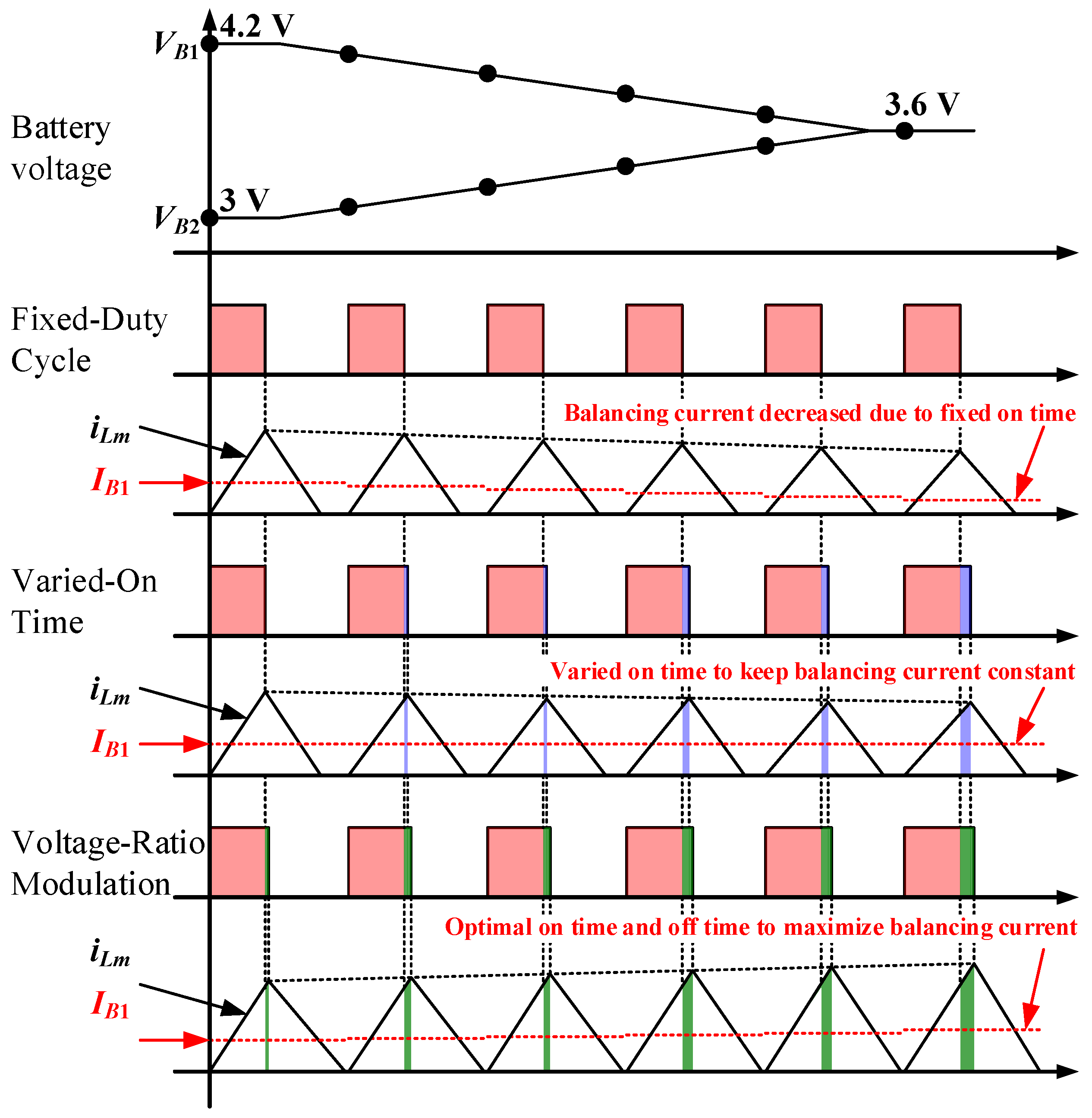
The main goals of the battery equalizer include high energy transfer efficiency, fast balancing speed, and safety in use. Moreover, the primary requirement is to achieve equilibrium rapidly. The key to the balancing speed is directly related to the balancing current. In the conventional control method, the duty cycle which means the conduction time of the main switch is constant as the buck-boost converter is used as an equalizer structure. Since the voltage of the high-SOC battery during the equalization process gradually decreases, the voltage difference between adjacent batteries becomes smaller so that the balancing current will drop if the conduction time does not change adaptively, resulting in a significant time cost in the equilibrium. Therefore, if the magnitude of the balancing current can be regulated according to the voltage of the battery, it could speed up the balance. In this circuit, the inductor current integrated over one switching period can be regarded as the average current from the battery while the main switch is turned on, so the balancing current can be controlled by changing the time interval of the conduction state. A concept diagram of the three strategies with balancing current control is shown in
Figure 4, where
iLm is the inductor current and
IB1 is the average current of battery
VB1.
In
Figure 4, the conventional fixed duty cycle (FDC) method does not adjust the duty cycle followed by the reduced battery voltage, so balancing current will decrease during the equilibrium process, resulting in a longer time to reach balance. The VOT method modulates the duty cycle of the main switch based on the battery voltage to maintain the magnitude of the balancing current. However, the conduction time cannot be optimized since only the voltage of the high-SOC battery is considered. To improve the balancing speed, the VRM method is proposed, which detects both the voltages of the adjacent batteries to calculate the distribution ratio of the conduction time and cut-off time of the main switch in a switching period for optimizing the energy that is stored and released by the inductor. Then, the average current can be maximized to effectively shorten the equilibrium process. The principle of control strategies is explained next.
3.1. Varied-on-Time Method
The adjacent cells can transfer energy between cells by manipulating the sequence of the switching operations of the buck-boost converter.
Figure 5 shows the diagram of the circuit structure and the waveform of the inductor current when the switches
Q1 and
Q2 are in conduction states sequentially. The energy of the inductor is charged when switch
Q1 is turn on as arrow in red color in
Figure 5. While switch
Q2 is turn on as arrow in blue color, the energy of the inductor is released.
VB1 and
VB2 are the adjacent voltages of the high-SOC battery and the low-SOC battery, respectively,
Ipk is the peak value of the inductor current,
IQ1,avg is the average current of main switch
Q1 as well as balancing current
IB1 of battery
VB1,
Ton is the conduction time of the main switch
Q1, and
TS is the switching period. The converter is operated in discontinuous conduction mode; hence, the inductor current will reduce to zero before the next switching cycle begins.
The relation between the inductor current and the battery voltage is shown:
Since the inductance is constant, it can be observed that the peak value Ipk of the inductor current is proportional to the battery voltage VB1. The integration of the inductor current over the switching period is the output charge of battery. When entering the balancing process, the voltage VB1 of the high-SOC battery will become lower. If the conduction time Ton of the switch Q1 is fixed, it can be seen from Equation (2) that the peak current Ipk will drop, which results in a prolonged equilibrium time. Hence, the VOT method is proposed to deal with this problem.
As discussed in
Figure 5, the balancing current of the battery
VB1 is the average current of the main switch
Q1, and it is related to the peak current of the inductor, as shown below:
Equation (4) can be derived from Equations (2) and (3). It can be seen from Equation (4) that the conduction time of the main switch Q1 can be controlled simply by detecting the terminal voltage of the high-SOC battery. Thus, in order to maintain the balancing current IB1, the conduction time Ton should be increased when the voltage of the high-SOC battery drops.
However, Equation (4) only detects the voltage of the high-SOC battery to calculate the conduction time of main switch Q1. Although it could prevent the prolonged balancing time from the balancing current decreasing due to the voltage drop, it cannot take the low-SOC battery into account to dispatch the optimal proportion of the conduction time and the cut-off time in a switching period. Therefore, this paper proposes a VRM method to optimize the conduction time and cut-off time, allowing the balancing current to be maximized based on the current battery voltage in a switching period and transferring energy from the high-SOC battery to the low-SOC battery more effectively to reduce the equilibrium time.
3.2. Voltage Ratio Modulation Method
To further increase the balancing current and achieve cell potential balance rapidly, a control strategy is proposed to effectively allocate the conduction time and cut-off time required in a complete switching period by detecting the voltages of two adjacent cells. Then, the converter is operated in critical conduction mode. With Equation (4), the relation between the conduction time and cut-off time can be written:
in which
Toff is the cut-off time of the main switch as well as the conduction time of
Q2 and
IB2 is the balancing current of battery
VB2. If the components in the circuit are all ideal and there is no loss in the circuit, the input power is equal to the output power as in Equation (6). The distribution ratio of conduction time and cut-off time can be arranged by Equation (7), which is directly related to the voltages of adjacent batteries.
From Equation (7), if the voltage of battery
VB1 is higher than that of battery
VB2, the conduction time of the main switch will be less than the cut-off time in a switching period. Furthermore, the sum of the conduction time and the cut-off time is the time of the switching period, then Equations (8) and (9) can be derived, respectively.
since the circuit operation should consider the dead time and time delay of the main switch and synchronized switch, the conduction time and cut-off time in the switching period are both concerned with an effective factor α, selected as 0.01 in this study. By Equations (8) and (9), it can be seen that the proportion of the conduction time of
Q1 is related to the low-SOC voltage of battery
VB2, and the cut-off time of
Q1 is associated with the low-SOC voltage of battery
VB1.
Figure 6a is the flow chart of the main control software program of the equalizer. TMS320F280049 produced by TI company is selected as a digital signal processor (DSP), and its maximum clock speed is 100 MHz. In the beginning, each required module is initialized and enabled. After entering the infinite loop, it continuously communicates with the ADAM-4117 voltage-sense module to obtain the terminal voltage information of each battery and is used in the balancing program.
Figure 6b shows the flow chart of the balancing process of the VOT method. Initially, it reads the information of the battery voltage and then calculates the voltage difference Δ
Vdiff between the maximum battery voltage
Vmax and the minimum voltage
Vmin. Then, the voltage difference is used to determine whether the battery balance state is reached by comparing with the critical value
Vlimit. Next, according to the aforementioned Equation (4), the conduction time is calculated in real time with the high-SOC voltage of battery condition. Furthermore, the energy flow of the converter can be controlled by the relation of the battery voltage of adjacent batteries.
Figure 6c depicts the flow chart of the balancing process of the VRM method. The different portion is that when the equalizer is in the balancing process, the proportion of the conduction time and cut-off time in a switching cycle will be calculated based on Equations (8) and (9). As a result, the balancing current can be further maximized to achieve balance rapidly.
4. Simulation Results
In this section, the simulation platform is established to verify the availability and correctness of the VOT method and the VRM method presented in this paper. Control strategies were tested on the platform and their results compared. The model UR18650ZY of a lithium-ion battery produced by SANYO was utilized in this examination. The specifications are shown in
Table 1.
The battery pack was composed of four batteries in series. In order to reduce the complexity and shorten the simulation time, the resistor and capacitor was adopted as the equivalent circuit model of the battery, of which the capacitance was 0.5 F and the internal resistance was 5 mΩ.
Table 2 lists the detailed simulation parameters of the bi-directional buck-boost converter. The initial voltages of the four batteries before the balancing process were 4.195 V, 3.715 V, 3.35 V, and 3.05 V, respectively. When the voltage difference between the maximum voltage and the minimum voltage of the batteries was lower than 50 mV, the balancing process was terminated.
Figure 7a–c are the simulation results of the FDC method, the VOT method, and the VRM method, respectively.
Figure 7a–c show that all of three control methods allow the four batteries to reach equilibrium, and the process is terminated as the voltage difference among batteries is within 50 mV.
Table 3 is a comparison table of the equilibrium time of the three control methods, and the VRM method saves 31.7% and 26.3% of the time compared with the FDC method and VOT method, respectively.
5. Experimental Results and Comparison
According to the simulation parameters, the experimental platform was also built to validate correctness and feasibility. Three bi-directional equalizer circuits with four batteries in series were tested, and corresponding strategies were implemented.
Figure 8 and
Table 4 show the practical platform of the equalizer system and equipment prepared in the test. In
Figure 8, it consists of the bi-directional buck-boost converter, battery pack, Micro-processor which is TMS320F280049 from Texas Instruments Incorporated, voltage sensing and computer interface. The platform could contain non-ideal conditions such as nonlinear component characteristics and temperature changes, which can more precisely verify the feasibility of the proposed control strategies. The comparison results were carried out in different control methods and test conditions with different orders of battery voltage. The balancing procedures of three cases using the three control strategies started with the same initial voltage, and they stopped when the voltage difference between cells was below 50 mV.
Table 5 shows the initial voltage conditions of three cases. The main purpose of the examination is that each equalizer can be well controlled according to the voltages of two adjacent batteries, and the proposed VRM method is verified in that it has the shortest equilibrium time under each test condition.
It can be seen from
Figure 9 that the energy of the high-SOC battery could be transferred to the low-SOC battery through the buck-boost converter, and the balancing process is completed when the termination condition is reached. From experimental results, it can be inferred that the three control methods are able to exhibit battery balance and the proposed VRM method can achieve equilibrium in the shortest time.
Table 6 shows the summarized elapsed time under the three cases. The VOT method calculates the conduction time by Equation (4), which can keep the balancing current at a constant value during the whole balancing time, and its performance is 16% better than the FDC method in case III. The VRM method uses Equations (7) and (8) to obtain the proportion conduction time and cut-off time in a switching period, which means the energy can be further effectively maximized to transfer between two adjacent batteries and speed up equalization. Therefore, the VRM method is the fastest way to reach a balanced condition and it can save 37.3% of equilibrium time compared with the FDC method while in case III.
The voltage difference among batteries will significantly rise during the long-term charging or discharging process due to the influence of internal impedance, nonlinear characteristics, and temperature. If the charging or discharging process is stopped early because of unbalance, it will result in lower utilization of the battery cells. Therefore, to verify the proposed equalizer could perform the balancing process while charging and discharging, the tests were carried out during charging and discharging, respectively.
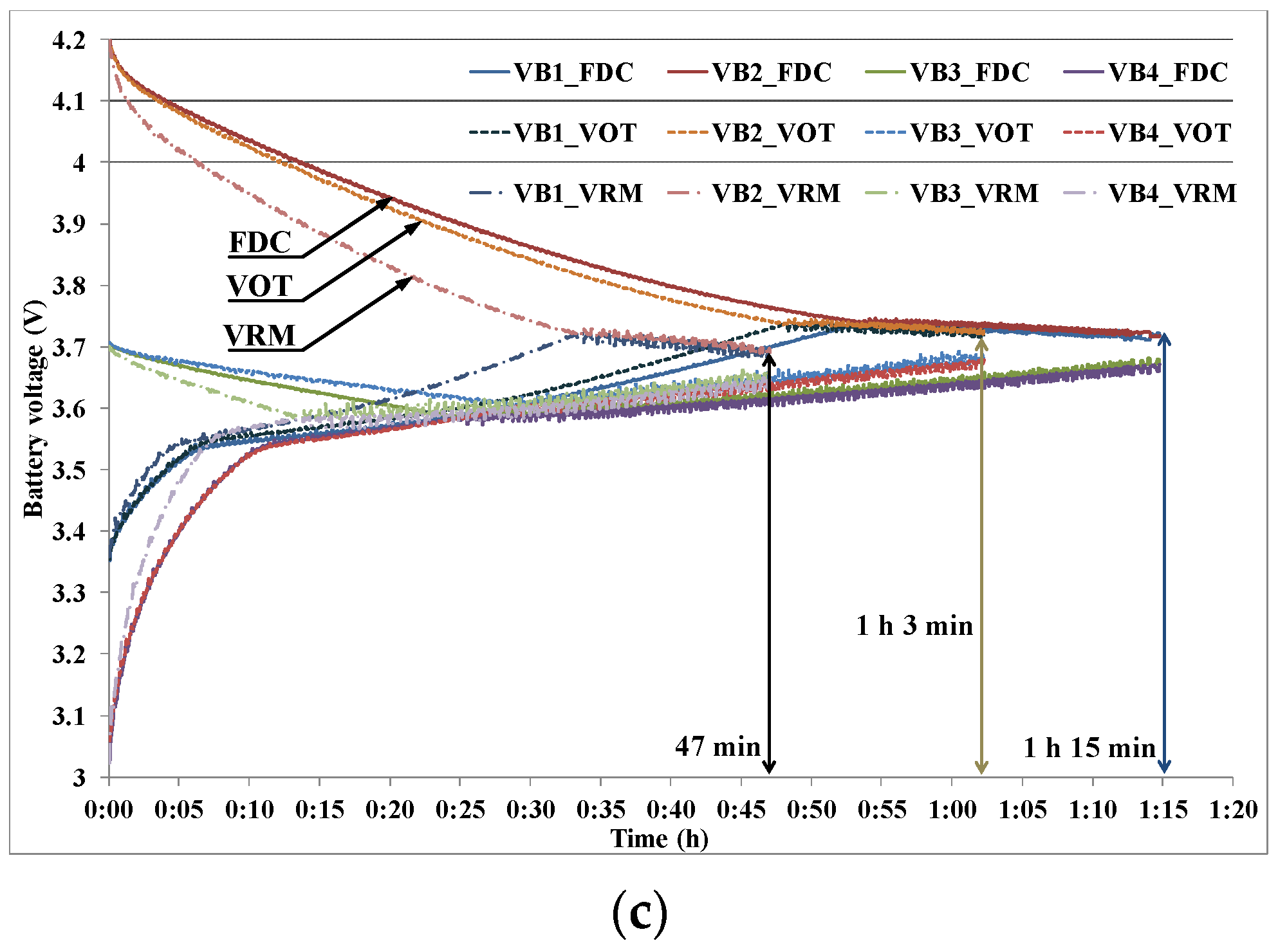
Table 7 is a list of battery voltages for charging and discharging test. Each battery voltage was set lower than 4 V initially in the charging test. When the highest voltage among batteries reached 4.2 V, the charger stopped charging. The discharging test was to set the battery voltage higher than 3.6 V initially. Moreover, the charger stopped discharging when the lowest voltage among batteries dropped to 3 V.
Figure 10 and
Figure 11 are the battery voltage curves under charging and discharging, respectively. The experimental results show that the proposed equalizer can implement battery balancing while charging and discharging situations. The voltage difference among the batteries was within 50 mV after 30 min and the process stopped until any battery voltage reached 4.2 V or dropped to 3 V.
6. Conclusions
This paper develops an active equalizer based on a bi-directional buck-boost converter, featuring a simple scheme, fast balancing speed, and easy implementation compared with other current-controlled equalizers. The proposed equalizer is capable of transferring energy bi-directionally between adjacent cells to make the battery module perform equalization rapidly. The implemented converter is operated in discontinuous conduction mode, so the magnetic component is small and the volume of the equalizer becomes compact. To deal with the problem of decreased balancing current in the later stage of equalization, which results in a prolonged equilibrium period, this paper proposes and realizes two methods, namely, the VOT method and the VRM method, to control the balancing current. The VOT method is able to perform a constant balancing current, while the VRM method enables maximum energy transfer during the entire equalization. The VOT method measures the voltage of the high-SOC battery to obtain the conduction time of the main switch; thus, the balancing current can be maintained at a constant value. However, the VOT method only detects the voltage of the high-SOC battery. It cannot take the low-SOC battery into account to dispatch the optimal proportion of the conduction time and the cut-off time in a switching period. Therefore, the VRM method is presented to use the voltages of the adjacent batteries in the described equation to calculate conduction time and cut-off time, which makes the energy transferring time almost fill up the entire switching period, and maximize the balancing current for the equalizer. The simulations and experiments are established to verify the proposed control methods. According to experimental results, the VOT method is validated to solve the reduced balancing current during the later equalization process and shortens the equilibrium time by 10.3%, 11.7%, and 16% compared with the conventional method. The VRM method is able to maximize the balancing current in the whole equalization process and shortens the equilibrium time by 35.9%, 36.6%, and 37.3% compared with conventional method. Furthermore, in the process of charging and discharging tests, the active equalizer proposed in this paper is verified to achieve equilibrium successfully. Finally, in future studies, the battery SOC could be considered and the long-term cycle life test could be performed to demonstrate the effectiveness of the proposed methods.


