Article

Delay Compensation Control Strategy for Electric Vehicle Participating in Frequency Regulation Based on MPC Algorithm

1
State Grid Hubei Electric Power Company Electric Power Research Institute, Wuhan 430070, China
2
College of Automation & College of Artificial Intelligence, Nanjing University of Posts and Telecommunications, Nanjing 210023, China
*
Author to whom correspondence should be addressed.
Electronics 2022, 11(15), 2341; https://doi.org/10.3390/electronics11152341
Submission received: 7 July 2022 / Revised: 21 July 2022 / Accepted: 25 July 2022 / Published: 27 July 2022
(This article belongs to the Section Electrical and Autonomous Vehicles)

Abstract

:
With the continuous increase of renewable energy, the power system will face the problem of insufficient frequency response capability. Electric vehicles (EVs) combine the characteristics of mobile energy storage and controllable loads and can provide capacity support in frequency control. However, as a distributed frequency regulation resource, there is inevitably a communication delay in the process of electric vehicles participating in frequency regulation, which will affect the stability of the system frequency. Therefore, this paper proposes a frequency regulation delay compensation control strategy based on model predictive control (MPC). Firstly, the model predictive control is utilized to design an electric vehicle frequency response model controller and establish a frequency regulation model of the power system containing electric vehicles; then, by establishing the selection rules of the control signal, the multi-step control signal is dynamically adjusted during the rolling optimization of the predictive model to form a delay compensation mechanism considering delay and packet loss; finally, multi-scenario simulation is conducted, and the results show that the proposed strategy can roll-optimize the auxiliary frequency regulation function of electric vehicles, significantly reduce the influence of communication time delay, and improve the system frequency stability.

1. Introduction

In recent years, in order to cope with the increasingly serious environmental and resource problems and achieve the purpose of “carbon peaking” and “carbon neutrality” [1,2], the development of a low-carbon economy has become a key issue. As one of the effective ways to achieve a low-carbon sustainable economy [3], electric vehicles (EVs) are a main measure to alleviate the problem of huge energy consumption and environmental degradation. With their fast power output and response characteristics, electric vehicle clusters can effectively improve the utilization level of fluctuating renewable energy in the power system [4,5] and ensure the safe and stable operation of large power grids. The access of electric vehicles to the grid has become one of the keys to the national energy strategy. With the introduction of the concept of electric vehicles accessing the grid [6], the issue of electric vehicles participating in grid frequency control has become increasingly widely considered [7]. In the “New Energy Vehicle Industry Development Plan (2021–2035)” issued by the General Office of the State Council, it is stated that it is necessary to promote the efficient coordination of new energy vehicles and renewable energy and coordinate the energy utilization of new energy vehicles and the coordinated scheduling of wind power generation and photovoltaic power generation.
Conventional frequency control [8,9,10] is involved in system power regulation by increasing the backup capacity of the generator on the generation side. After the large-scale integration of renewable energy sources (such as wind power and photovoltaics) [11,12,13], the power rapid response ability of the generator set is greatly limited due to economics and practicality. In the case of a sharp drop in system frequency due to the loss of a large amount of wind power, the low-frequency load reduction strategy can lead to frequency collapse events if it is not effective in time [14]. The suddenness and urgency of events place higher requirements on the speed of stable control of the grid frequency [15]. There have been several studies on the participation of electric vehicles in the integration of new energy grids and frequency control by domestic and international academics. Guille et al. [16], by establishing the static frequency characteristic model of EV charge and discharge, realized the coordinated control of EV charge and discharge so that the EV can quickly and effectively switch between controllable load and distributed power generation. An improved charging and discharging scheduling strategy for electric vehicles is proposed in [17]. The strategy aims to improve the frequency regulation efficiency of electric vehicles by constructing a two-way interactive electric vehicle intelligent network system and related communication mechanisms. Medina et al. [18] propose a joint optimization method for load frequency control that takes EV-assisted frequency regulation into consideration. This method effectively improves the steady-state response speed and frequency regulation performance of load frequency control. J. Li and his research team in [19] analyze the restrictions on the participation of electric vehicles in the frequency control of the power grid and propose the control strategy of the primary frequency and secondary frequency regulation of the electric vehicles participating in the power grid. Based on this, the authors in [20] further improve the control strategy and present a load frequency control (LFC) method based on increased control signals for plug-in hybrid automobiles.
Most of the existing frequency control methods in [21] assume that the communication system is capable of controlling massively distributed loads instantly, without considering the effect of communication delays in the frequency regulation process. In practice, the available power of the controllable EV cluster is collected and transmitted to the system control center, which then adopts the corresponding control strategy and calculates the control amount to be transmitted to each controllable load cluster [22]. As a result, control systems and terminal devices inevitably generate time delays. Due to the impact of communication delays, the load cannot receive control instructions synchronously, and the time required to adjust the error of the system frequency increases. H. Fan et al. [23] studied the effect of using EV to participate in the delay of communication in primary frequency regulation on the effect of frequency modulation in multi-region systems but did not use it as a guide to develop frequency control strategies; N. Zhao et al. [24] propose a control strategy for IAC aggregation and generator output to participate in the frequency regulation of the power system. Since demand response behavior is related to time delay, MPC-based compensation strategies are used to reduce the impact during frequency control. C. Peng et al. [25], by analyzing the interval distribution characteristics of TCP/IP communication network delay, designed the time delay compensation strategy of an LFC system with random interval distribution delay to eliminate the interference caused by communication delay on electric vehicles entering the network. From the above analysis, it can be seen that when the frequency is adjusted, the communication delay has a certain negative impact on the dynamic response of the system. However, much of the current work is mainly focused on analyzing the effects of delays based on communication systems or power systems, while relatively few studies consider compensation for communication delays in the integrated communication dimension and power dimension.
In order to meet the requirements of the speed of electric vehicle frequency regulation and compensate for the communication delay in the frequency regulation process, this paper proposes a control strategy for the compensation of electric vehicle frequency delay based on the MPC algorithm. The model predictive control is utilized to design an electric vehicle frequency response model controller and establish a frequency regulation model of the power system containing electric vehicles; by establishing the selection rules of the control signal, the multi-step control signal is dynamically adjusted during the rolling optimization of the predictive model to form a delay compensation mechanism considering delay and packet loss. The performance of the proposed controller model and compensation strategy is evaluated by MATLAB/Simulink simulation, and the effectiveness of the compensation strategy is verified, which shows that the compensation strategy can improve the frequency support capability of electric vehicle cluster connection.
The rest of this paper is arranged as follows. In Section 2, the overall framework of electric vehicle frequency modulation is introduced. In Section 3, by analyzing the model predictive control theory, the predictive model and rolling optimization algorithm are studied. This section also establishes the aggregation model of electric vehicles, the frequency response model, and other models in detail, which makes preparations for the design of the time delay compensation controller in the next section. In Section 4, the influence of communication delay on system frequency modulation is analyzed, the selection rules of control signal are established, and the active compensation strategy of electric vehicle frequency modulation delay is proposed. In Section 5, the performance of the proposed controller model and compensation strategy is evaluated by MATLAB/Simulink simulation. Finally, in Section 6, the contents of the previous four sections are summarized, and the deficiencies and improvements of the research are put forward.

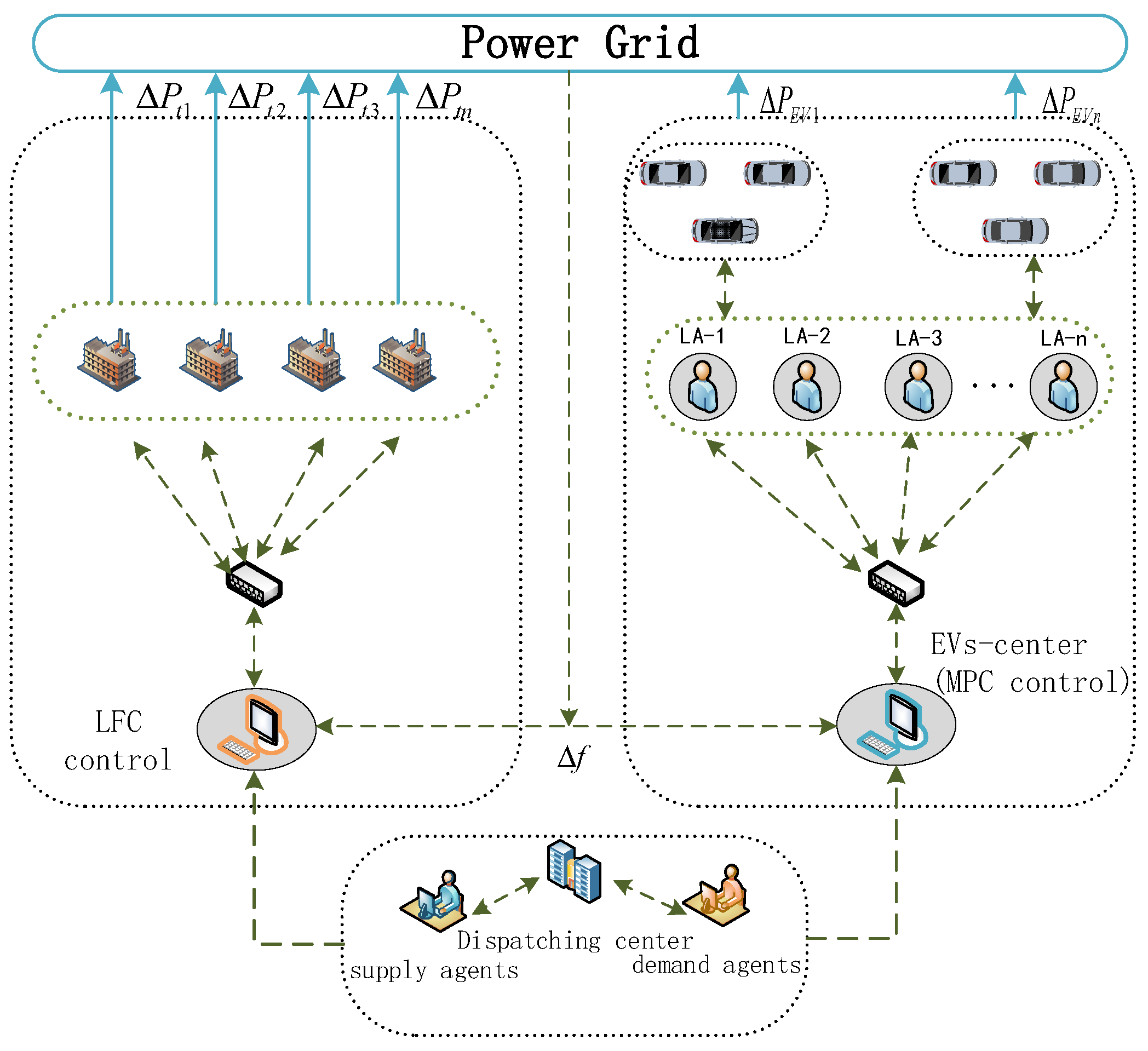
2. MPC-Based Electric Vehicle Frequency Regulation Framework

In the frequency control frame, as shown in Figure 1, the scheduling center allocates capacity to the generator and the aggregate EV. The management structure of hybrid vehicles includes a central controller, LAs, and EV units. In the management structure, LAs are used to aggregate EV units in the same area to provide frequency regulation services; the EVs control center obtains the frequency reserve potential of the aggregated EVA units from each load aggregator by means of a quantitative estimate a few days prior. Together with the LFC central control, the central controller sends a frequency response signal to the LAs if the frequency fluctuates beyond an acceptable value.

3. Frequency Control Strategy of Electric Vehicles Based on MPC

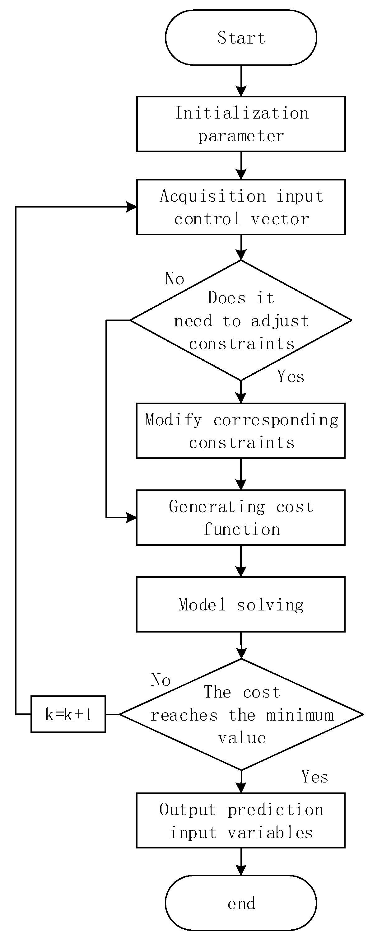
3.1. Model Predictive Control Theory Introduction

By solving the optimization problem for each sample point in a limited time, the model predictive control current sequence is derived. Consider the following scheme.
x k + 1 = f k ( x k , u k )
where x k and u k are vectors composed of a series of finite scalars, assuming that the cost function is non-negative:
min U J ( U ( k ) ) 0
The constraints for the control state and input are
x k X k , u k U k , k = 0 , 1 , , n
Suppose there is a system state that can be controlled to the initial value and the utility function is 0:
f k ( 0 , u ¯ k ) = 0 g k ( 0 , u ¯ k ) = 0 u k U k ( 0 )
The MPC algorithm will eventually generate a control sequence that can track a set trajectory and satisfy both state and control constraints, as well as guarantee that the cost function is minimized. The specific process is shown in the following Figure 2.

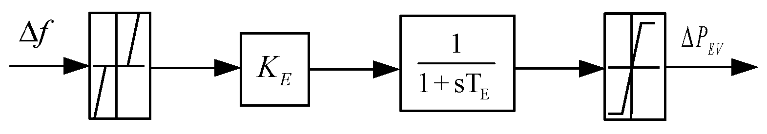
3.2. Electric Vehicle Aggregation Model Construction

In order to explore the frequency response characteristics of EV clusters, a dynamic model of EV participation in one-time frequency regulation is constructed. According to the direction of transferring electricity between the grid and the EV, this can be divided into two kinds of working states: in the “charging state”, or “CS”, the electric vehicle (EV) draws electricity from the grid at its rated active power; in the “discharging state”, or “DS”, the EV feeds back electrical energy to the grid at its rated active power. The individual differences among EVs are ignored to simplify the study, and the combined electric vehicles are divided into categories based on the aforementioned two states. To change the power system’s frequency, the suitable EVs can be selected depending on frequency fluctuation. Further considering the different cluster classifications of electric vehicles participating in system frequency regulation, it is necessary to set the battery charge and discharge priority according to different state of charge (SOC) values. When the power battery’s SOC value is between 20% and 40%, in order to ensure the travel needs of electric vehicle users, the charging pile is charged by default when it is connected to the electric power system, and it can participate in the drops of grid frequency; when the SOC value is between 40% to 60%, the regulation margin of the internal electric vehicle battery is large, and it can participate in the up-and-down adjustment of the system frequency at the same time; when the SOC is between 60% to 80%, for electric vehicles that participate in the grid frequency regulation, only the discharge behavior is carried out, and participation in the system frequency upregulation is allowed. Additionally, the power limit of the polymer electric vehicle itself is considered. The controllable charge and discharge power should meet
0.2 P lim Δ P E V 0.8 P lim
When an EV participates in frequency regulation as a distributed power supply or energy storage element, its discharge static characteristic model consists of EV charge and discharge frequency response coefficient K e v and a first-order inertial system. It is uniformly set as the charge and discharge coefficient of electric vehicles, which is due to the fact that the difference between the charging coefficient and the discharge coefficient is very small. For N electric vehicle aggregates, they are defined as K e v 1 , K e v 2 K e v n .
When an electric vehicle participates in frequency regulation control, its frequency response characteristic [26] is
Δ P e v i = 0 Δ f Δ f dead K e v i Δ f T e v i s + 1 Δ f Δ f max P max Δ f > Δ f max K e v i Δ f T e v i s + 1 Δ f Δ f min P min Δ f < Δ f min
where Δ P e v i is the charging load of an electric vehicle during frequency regulation; K e v is the frequency regulation coefficient of an electric vehicle, determined according to the state of charge and frequency deviation; P min is the maximum load that can be reduced under the current charging state of the electric vehicle; P max is the maximum load that can be increased under the current charging state of the electric vehicle; T e v 1 , T e v 2 and T e v n are time constants of an EV in corresponding EV aggregators; Δ f dead is the located frequency regulation dead band of electric vehicle. When Δ f is in the dead zone, the frequency regulation strategy of an electric vehicle is not triggered to ensure the general charging demand of the electric vehicle.
In Formula (2), the electric vehicle primary frequency control model is introduced, as depicted in Figure 3.
Therefore, all EVAs in the system under the central controller (EVs) of the electric vehicle have the following power controllability:
Δ P e = i = 1 N Δ P e v i
where Δ P e is the sum of the power of all EVs, and N represents the number of EVs involved in frequency regulation.

3.3. Frequency Control Strategy of Electric Vehicles Based on MPC

Figure 4 shows the system frequency response model proposed in this paper, which includes the traditional LFC model and the model predictive control of the polymer electric vehicle. Among them, H, D, K, R, and N are equivalent inertia time constants, system damping coefficients, LFC controller integration gain, power system speed regulation coefficients, and the number of EVAs; T g and T t are the time constants for the governor and turbine, respectively; U e is the control signal of the EV controller, Δ f and Δ P g represent the variance in frequency and the shift in the governor’s position, respectively; Δ P e and Δ P t are the changes of the total output power of the electric vehicle aggregator and turbine, respectively; Δ P L is load disturbance.; and α 1 and α 2 are the frequency deviation weights to the main controller and electric vehicle controller, respectively, and the number of α 1 and α 2 equals 1.
The frequency dynamics of analogous governors, turbines, and power systems are graphs for the host controller to locate differential equations:
Δ f ˙ ( t ) = 1 2 H Δ f ( t ) + 1 2 H Δ P g ( t ) 1 2 H Δ P L ( t ) Δ P e ( t )
Δ P ˙ t ( t ) = 1 T t Δ P t ( t ) + α 1 T t Δ P g ( t )
Δ P ˙ g ( t ) = 1 R T g Δ f ( t ) 1 T g Δ P g ( t ) + 1 T g Δ P 1
Δ P ˙ e ( t ) = 1 T E ( α 2 N K E U e Δ P e )
The state space dynamic frequency model of a power system can be expressed as follows:
x ˙ ( t ) = A x ( t ) + B u ( t ) + F w ( t ) y ( t ) = C x ( t )
where state vectors are x ( t ) R n , u(t) is the aggregation control vector for the EV, and y(t) is vector output from the system, with w(t) being the interference vector, defined as
x ( t ) = c o l [ Δ f Δ P g Δ P t Δ P 1 Δ P e ]
y ( t ) = Δ f , w ( t ) = Δ P L
where Δ P 1 is the auxiliary variable, and a system model in linear state space is exported.
Δ P ˙ 1 = K Δ f
The following contains the precise formats for the system control matrix A, input matrix B, output control matrix C, and disturbance matrix F.
A = D 2 H D 2 H 0 0 1 2 H 1 R T g 1 T g 0 1 T g 0 0 α 1 T t 1 T t 0 0 K 0 0 0 0 0 0 0 0 1 T E
B = 0 0 0 0 N K E α 2 1 T t T
C = 1 0 0 0 0
F = 1 2 H 0 0 0 0
By discretizing Equation (11), we are able to obtain an equation-based state-space model for linear discrete systems as follows:
x ( k + 1 ) = A ¯ x ( k ) + B ¯ u ( k ) + F ¯ w ( k ) y ( k ) = C x ( k )
where T is the sampling period.
A ¯ = e A T , B ¯ = 0 T e A s B d s , F ¯ = 0 T e A s F d s
Define the forecast range Np and control range Nc and NcNp. Based on the discretization formula, the following predictive model is derived at time k:
X k = A ˜ x k + B ˜ U k + F ˜ W k
where
X ( k ) = x ( k + 1 k ) T x ( k + 2 k ) T x ( k + N p k T T
U ( k ) = u ( k k ) T u ( k + 1 k ) T u k + N c 1 k T T
W ( k ) = w ( k k ) T w ( k + 1 k ) T w ( k + N p 1 k T T
A ˜ = A ¯ A ¯ 2 A ¯ N p
B ˜ = B ¯ 0 0 A ¯ B ¯ B ¯ 0 A ¯ N p 1 B ¯ A ¯ N p 2 B ¯ A ¯ N p N c B ¯
F ˜ = F ¯ 0 0 A ¯ F ¯ F ¯ 0 A ¯ N p 1 F ¯ A ¯ N p 2 F ¯ A ¯ F
A linear discrete system’s state space model is as follows:
Y k + 1 = G x x k + G u U k + G w W k
where
Y ( k + 1 ) = y ( k + 1 k ) T y ( k + 2 k ) T y k + N p k T T
C ˜ = d i a g C C C N p S x y = C ˜ A ˜ , S u y = C ˜ B ˜ , S w y = C ˜ F ˜
For the following objective optimization issues, set the reference value of frequency deviation to zero and determine the control signal by determining the minimal control cost.
lim U J = i = 1 N p y ( k + i | k ) q i 2 + i = 1 N c u ( k + i 1 | k ) r i 2
where q i and r i are positive diagonal weighted matrices, the objective function minimizes the frequency deviation within the prediction range, and the control cost within the control range can be rewritten in matrix form:
min U J ( x ( k i ) , U ( k i ) , d m ) = Q Y ( k i + 1 k i ) 2 + R U ( k i ) 2 s . t .   ϒ U ( k i ) γ
The optimal control objective function can be further converted into
min U J ( U ( k ) ) = U ( k ) T H U ( k ) + S ( k ) U ( k )
where
H = S x y T Q S x y + R
S ( k ) = 2 S u y T Q S x y x ( k ) + S w y W ( k )
Q = d i a g q 1 q 2 q N p   R = d i a g r 1 r 2 r N c
Υ = J B ˜ J B ˜ , γ = J A ˜ x ( k ) + J F ˜ W ( k ) N J A ˜ x ( k ) J F ˜ W ( k ) + M
J g = 0 0 0 0 1   J = d i a g J g J g J g N p
N = N m N m N m T N p ,   M = M m M m M m T N p
By solving the above equation, the optimal control sequence is
U * ( k ) = u ( k k ) T u ( k + 1 k ) T u k + N c 1 k T T

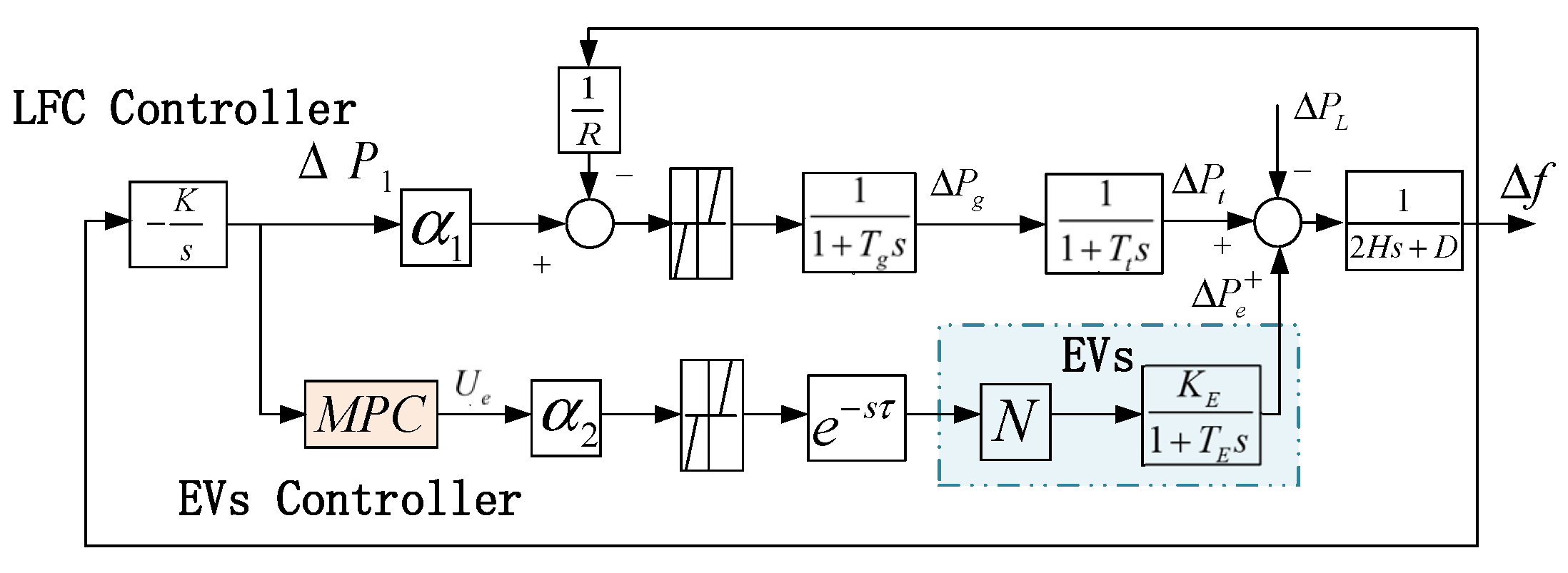
4. Electric Vehicle Frequency Regulation Delay Compensation Strategy

4.1. The Effects of Communication Delays on the Participation of EVs in Frequency Regulation

The performance of an originally calibrated physical system deteriorates because of the delays in the communication network. This situation can lead to system instability in severe cases. The impact of random delays in control signals is mainly reflected in immediate control. The presence of long random delays can cause timing errors in the output variables, as well as loss of variable data. It is simpler to use a zero-input control method. The zero-order hold (ZOH) method avoids the unsmooth switching of control inputs, but it is difficult to maintain the previous value. However, maintaining the value at the previous moment in time inevitably leads to conservatism, making it difficult to achieve the desired system performance. In the presence of both packet loss and time delay in the network, the system model can take many different forms. This does not allow the system to be described in terms of an ideal time delay system. For the purposes of this paper, a packet is considered to be dropped once if no packet is reached within a sampling period.
Definition 1. 
Input latency can be expressed as
0 τ τ max T
where T is the sampling period, τ max is a positive integer, and N p τ max is satisfied.
τ max T is defined as the time delay’s maximum value.
As shown in Figure 4, LA implements a delay compensator that selects the appropriate control value applicable to the current time interval based on the delay. Consequently, the impact of delay is eliminated, and system performance and stability are enhanced.
The presence of latency causes the data packets to be out of order, which will inevitably lead to data packet loss. In the interval [ ( k 1 ) T , k T ] , the following rules are described as follows:
δ i = min { i | τ k i i 0 } ,   i = 0 , 1 , , τ m
Since the controller actively discards packets in disorder, the packet loss factor needs to be considered. Let θ k be the number of consecutive active packet drops before timestamped k packets and θ k [ 0 , s ] ,   s τ max ; according to the rules of active packet drops, we get θ k as
θ k = min { j | τ k j τ k j + 1 i T ,   i = 0 , 1 , , τ max ,   j = 0 , 1 , , s }

4.2. Active Compensation Strategy for Frequency Regulation Delay of Electric Vehicles

In this section, an active compensating control strategy based on the MPC technique is employed to correct for the impacts of offsetting input delays.
Considering delay and packet loss, the state-space dynamic frequency model (16) of the power system can be described as
x ( k + 1 ) = A ¯ x ( k ) + B ¯ U * ( k ) + F ¯ w ( k ) y ( k ) = C x ( k )
where U * ( k ) is the best control volume at moment k of the optimal control sequence U * .
Predictive control sequences with a timestamp are transmitted to LAs as separate packets. The delay compensator is set at the LA, and the corresponding control value applicable to the current time step is selected based on the delay, thereby eliminating the effect of delay and improving system performance and stability. Depending on the delay and packet loss, three compensation mechanisms can be considered independently.
(1) The number of sample periods δ k for which the communication’s lengthy delay lasts is 1, and the controller receives a timestamp of 1 if the network transmission delay is less than one sampling period. Consequently, the system’s ideal control input is
U * ( k + 1 ) = u ( k + 1 k )
(2) If the network transmission time delay is more than one sampling cycle, the linked output power signal from the EVs that finally travel from the LA to the grid via the EV control center to participate in frequency regulation is more than one sample cycle. No data are received during a control cycle as a result. The controller gets a time stamp of 0, and the number of sample periods δ k for which the communication’s lengthy delay lasts is higher than 1. Consequently, the system’s ideal control input is
U * ( k + δ k ) = U ^ * ( k + δ k 1 ) + u ( k + δ k k ) u ( k + δ k 1 k )
(3) If an approaching control cycle involves n sets of control increment sequences, the minimum packet loss A of the n sets of sequence timestamps θ k will be used to determine when to employ the control increment sequence. Consequently, the system’s ideal control input is
U * ( k + 1 ) = U ^ * ( k ) + u ( k + 1 k θ k ) u ( k k θ k )
In conclusion, the ideal control sequence U * may be identified when the transmission time delay has been considered. The combination of the MPC algorithm and time delay compensator in the process of electric vehicle participation in frequency regulation can ensure that the control center can output the optimal or sub-optimal electric vehicle raised regulation frequency, thus playing a role in compensating the adverse effects of network time delay on system performance, with good control performance.

5. Simulation Results and Analysis

In MATLAB, the above load frequency control simulation model considering communication delay is established, and the parameters of the smart grid are set as follows: T t = 0.3, T g = 0.08, H = 6, D = 1, R = 0.05, K = 1. Using two eviction aggregators, the charge–discharge time constant of the electric vehicle is set to T e v 1 = T e v 2 = 0.035, the charge–discharge coefficient is K e v 1 = K e v 2 = 2 × 10 3 , and the power constraint of the electric vehicle is [−0.5,0.5].

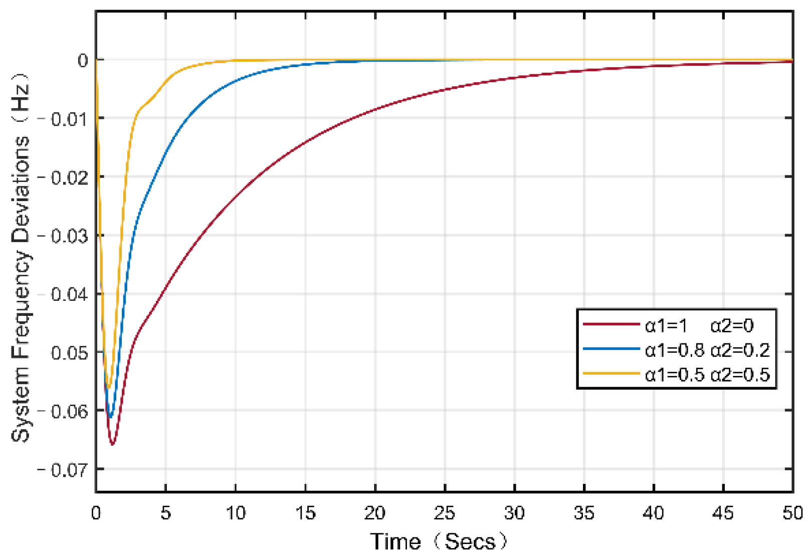
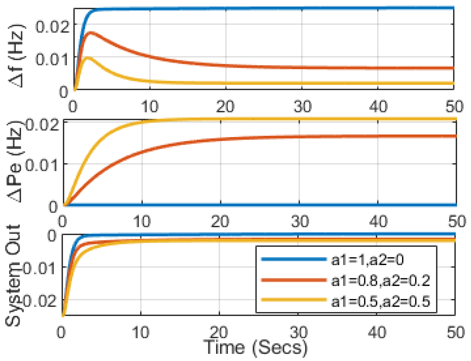
5.1. Effect of Aggregated EV Involved in Dynamic Response on System Frequency Stability

In this case, the article focuses primarily on comparing the contributions of generators and aggregated EVs rather than exploring communication latency impact. By analyzing different participation factors, different EV participation factors α in three cases were discussed. Case 1: α 1 = 1, α 2 = 0; case 2: α 1 = 0.8, α 2 = 0.2, and case 3: α 1 = 0.5, α 2 = 0.5. Under a step disturbance of 0.025 p.u, Figure 5 depicts the system dynamic response of various EV participation factors, which shows that cases 2 and 3 with aggregate EV participation have a positive effect on improving the frequency response compared to case 1. In addition, by increasing the participation factor of the aggregate EV, the frequency deviation of case 3 is further reduced compared to that of case 2, which indicates that the greater the proportion of EV participation in frequency regulation, the better the frequency response performance. As can be seen from Figure 6, the EV responds faster than the generator because the adjustment inertia constant is smaller than the generator. It can also be seen from the system output curve that a larger EV participation factor will lead to an overshoot of frequency regulation, and the selection of suitable α 1 and α 2 values conducive to better system performance proves the effectiveness of the coordinated control strategy.

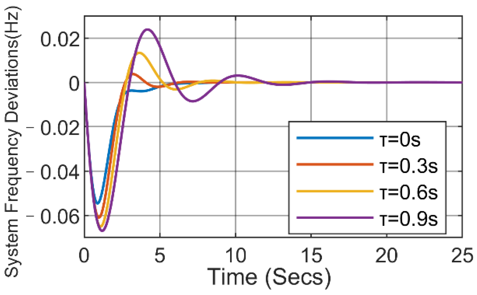
5.2. The Effect of Communication Delay on the Power System Frequency Response

In view of the communication delay in the system, we evaluated the system’s response to EV communication delays. The EV participation factor coefficient provided to the system refers to case 2 in usage scenario 1 and assumes that the increment of the step disruption is the same as in Scenario 1. Different communication timing delay values are introduced to examine the influence of communication delay on the system, and the dynamic performance is displayed in Figure 7. As the delay increases, the frequency deviation also increases significantly. Communication delays negatively affect the electricity system’s frequency response, and when the communication delay exceeds a certain threshold, the performance of the power system will gradually deteriorate. However, considering that there is no EV control loop, the use of EVs in frequency regulation can improve the frequency’s lowest point, which also shows the advantages of the control strategy we have proposed.

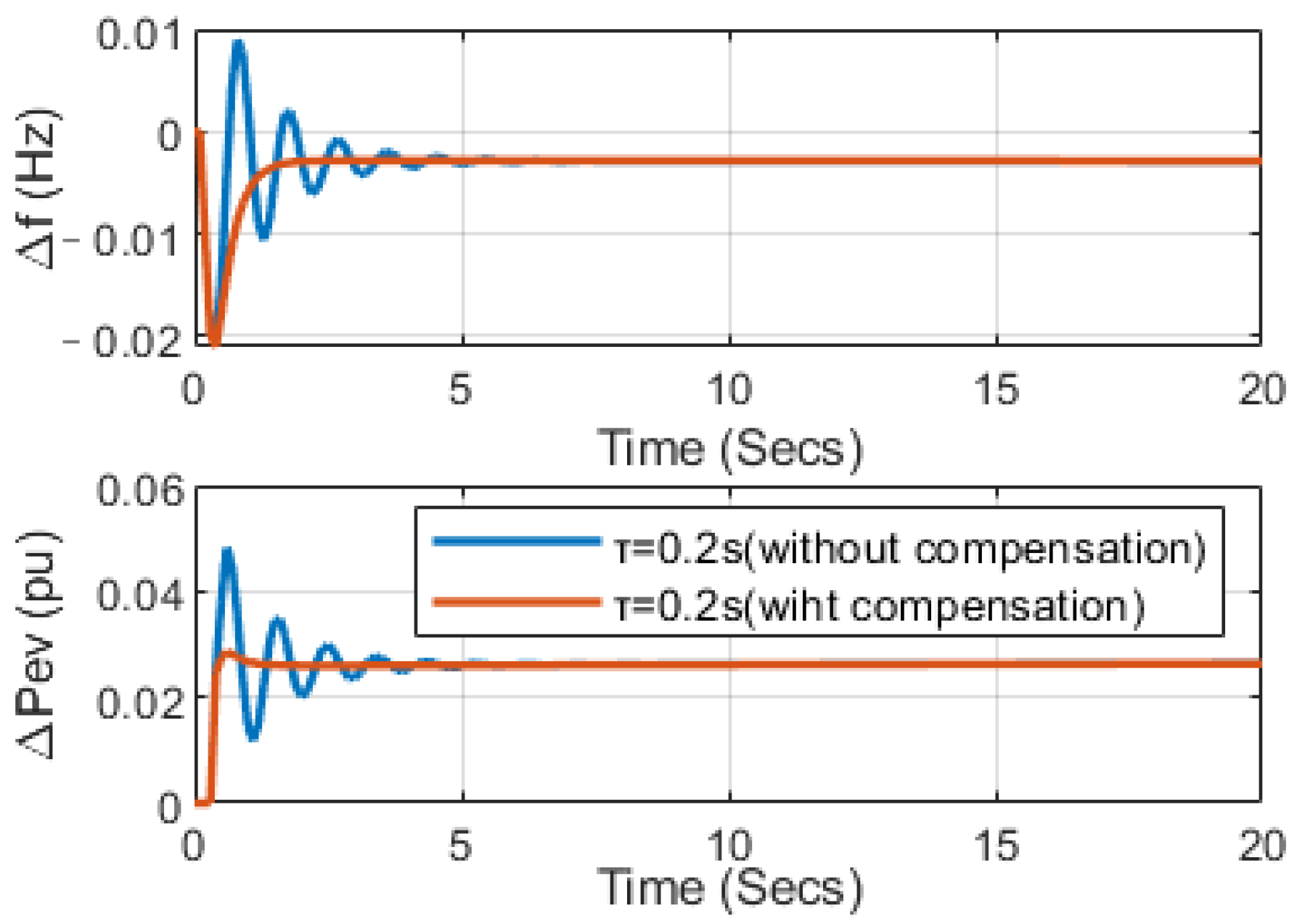
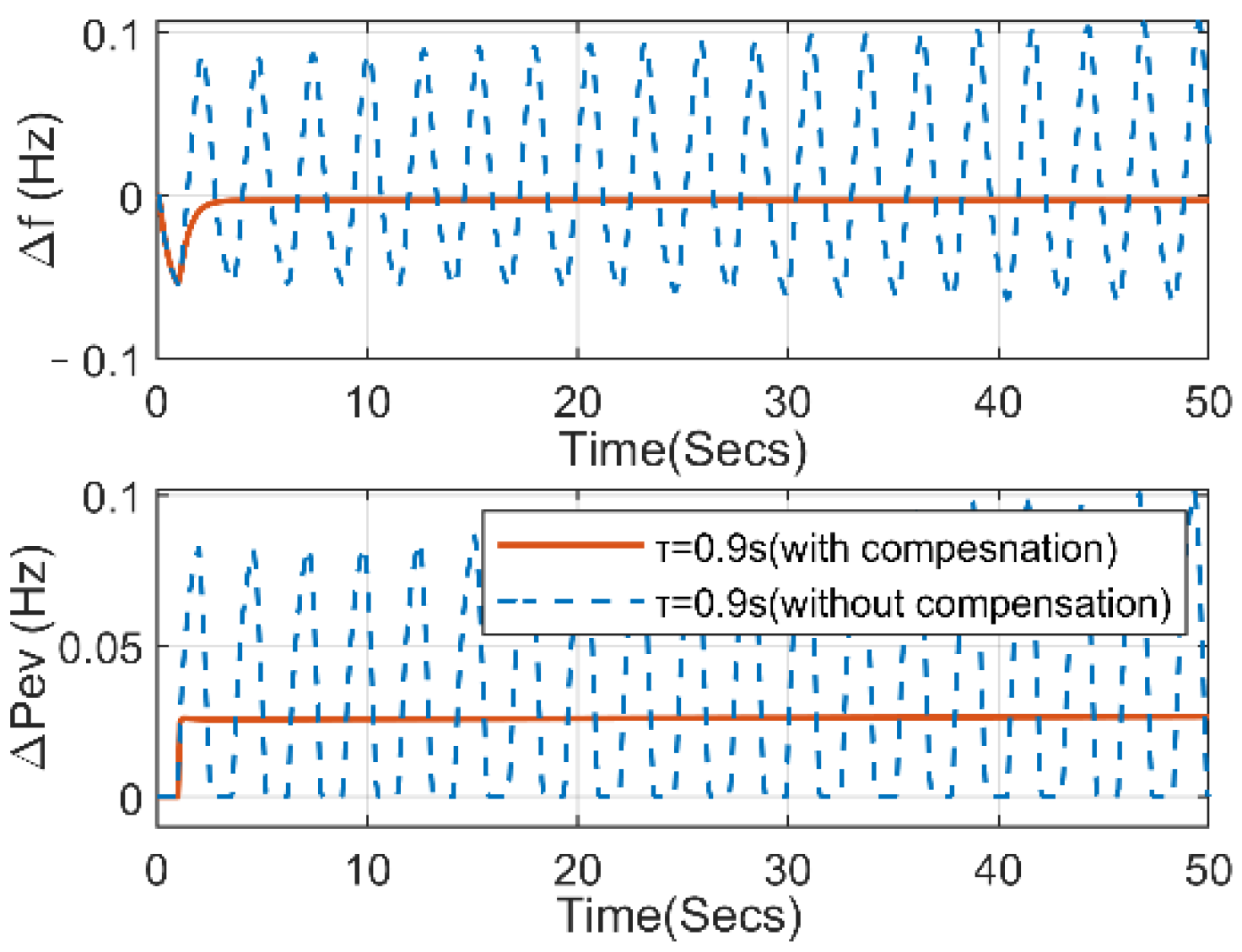
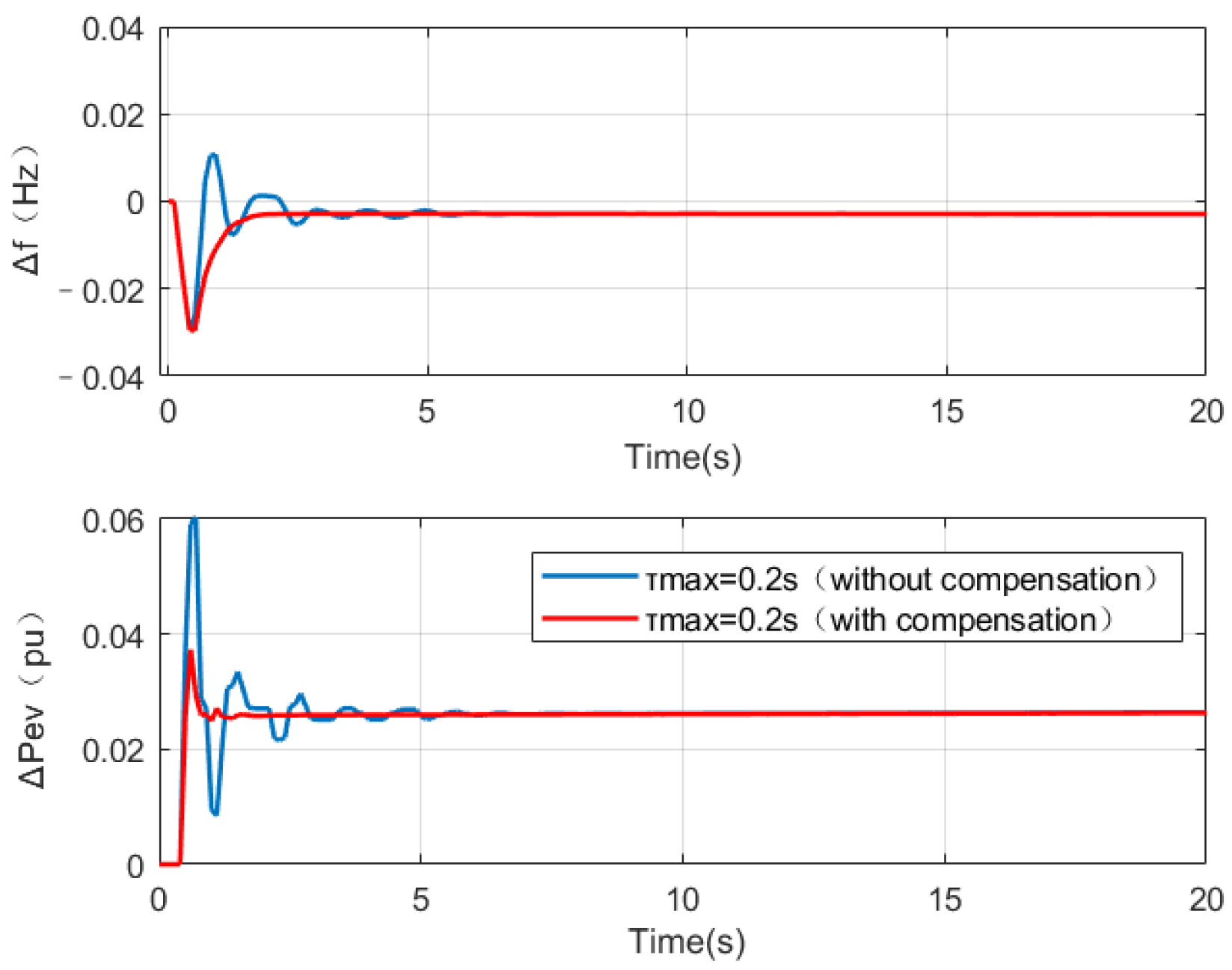
5.3. Comparison Effect of System Performance with or without Delay Compensation

As increasing numbers of EVs are connected to the power system, the power system has low inertia characteristics, which can easily lead to frequency stability problems and affect frequency regulation. At the same time, in actual conditions, communication delay is mostly random delay. Therefore, in the third scenario, aiming to confirm the robustness of the suggested control mechanism and the efficacy of the delay compensation approach, it is assumed that the inertia time constant of the power system load is reduced by 10% of the original state. Using the parameters in case 2 of Scenario 1, we consider the contribution to a system with a 10% inertia reduction and assume the same step load disturbance as before. First, for a system with a 10% reduction in inertia, Figure 8 and Figure 9 show a comparison of the frequency response and power output with or without delay compensation, as well as the different delays. As shown in the figure, when τ = 0.2 s in the system, the compensated system is faster and more stable than the uncompensated system, illustrating the effectiveness of the delay compensation strategy. As can be seen from Figure 9, when a delay is introduced into the system without delay compensation, the system oscillates violently until it loses stability. It can be observed that when the system is unstable due to the influence of communication delays τ = 0.9 s, the delay compensation method provides better performance, so the frequency response and output power changes of EVs are not divergent.
In order to further reflect the superiority of this compensation method, we consider using random communication delay for a system with a 10% reduction in inertia, where the maximum delay is the sum. Figure 10 and Figure 11 illustrate a comparison of the frequency response and power output of a 10% system inertia reduction with and without delay compensation under different random delays. The results show that without the delay compensation strategy, the dynamic response process with random delay leads to significant oscillation of the load output, which affects the service life of the device itself. The results show that even if the communication delay is simulated in the face of a random τ max = 0.2 s and τ max = 0.7 s delay closer to the actual situation, the delay compensation method can effectively reduce the amount of frequency oscillation in a shorter adjustment time and maintain stability.

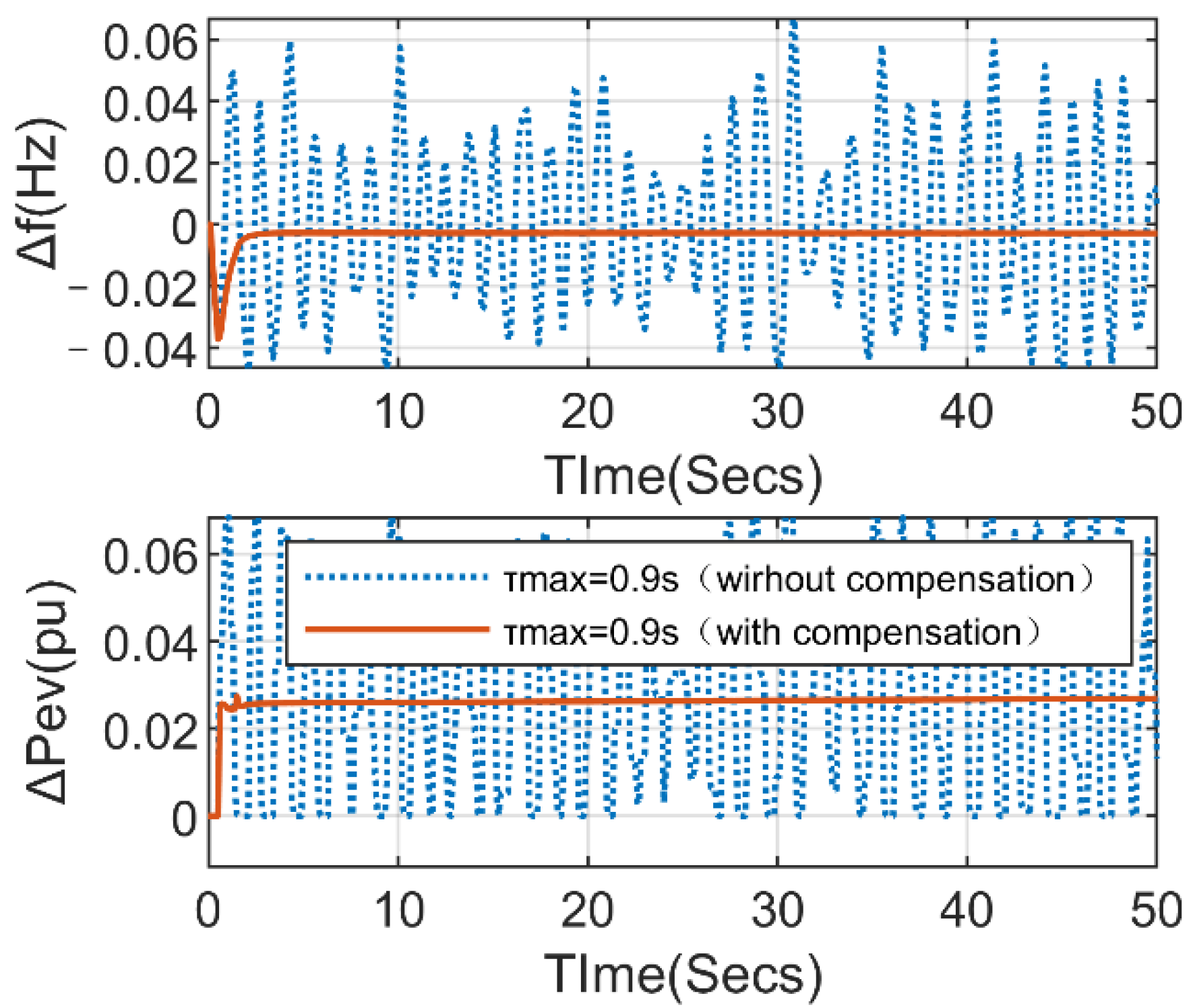
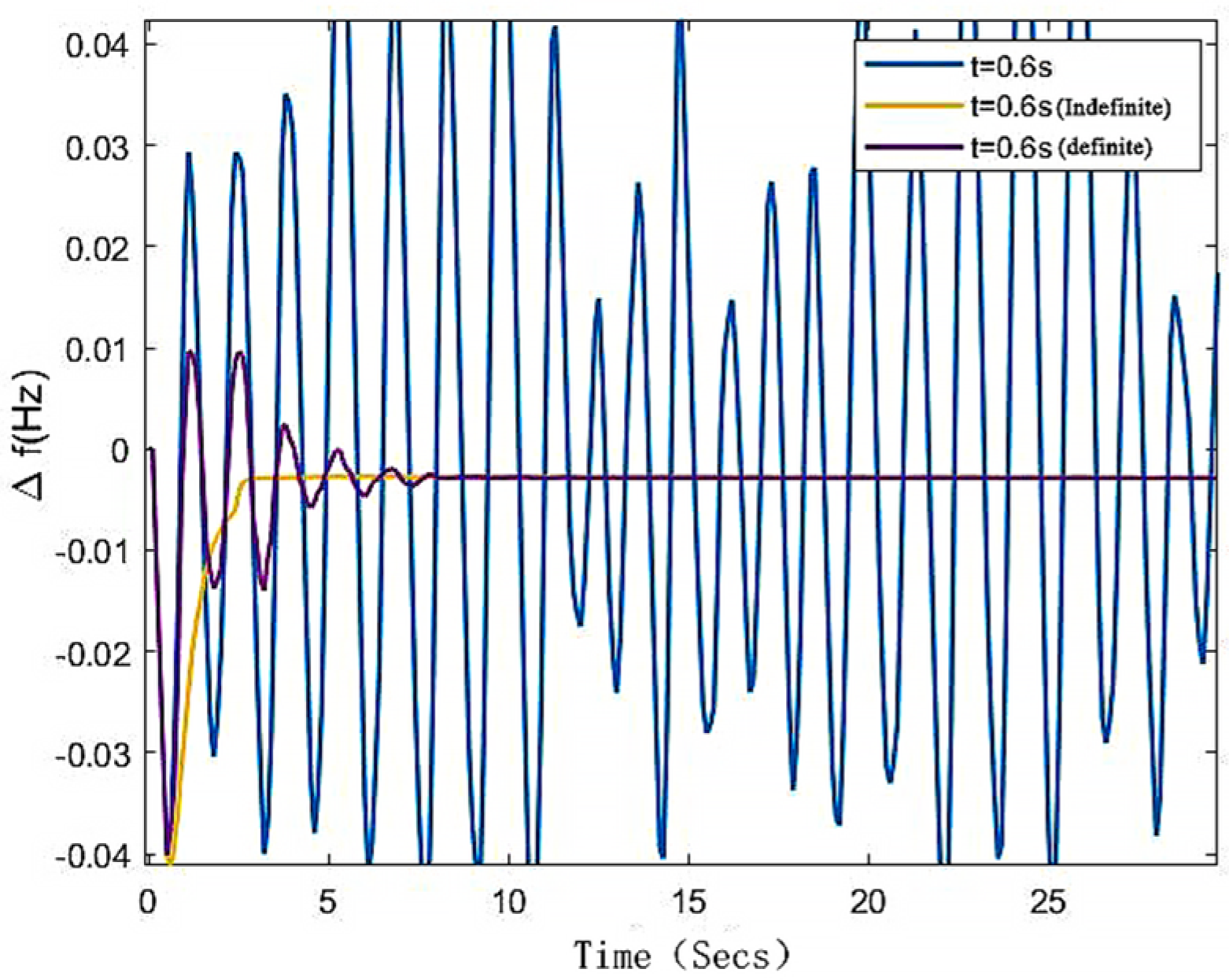
5.4. Dynamic Performance of Systems with Random and Variable Delays under Different Compensation Strategies

To examine the efficacy of the suggested delay compensation technique, we evaluated the impact of EV communication delays under different compensation methods. The EV participation factor coefficients provided for the system are referenced using Scenario 2 in Scenario 1 assuming the same step disturbance increments as in Scenario 1. The simulated indefinite delay is 0~0.6 s. The Figure 12 shows that the delay compensation method in [24] can also effectively reduce the amount of frequency oscillation within a certain regulation time, but it takes some time for the oscillation to stabilize. In comparison, the compensation method proposed in this paper considering random indefinite delay can quickly adjust to a stable state without overshooting oscillations, which is significant. This demonstrates the advantages of the proposed variable delay compensation control strategy.

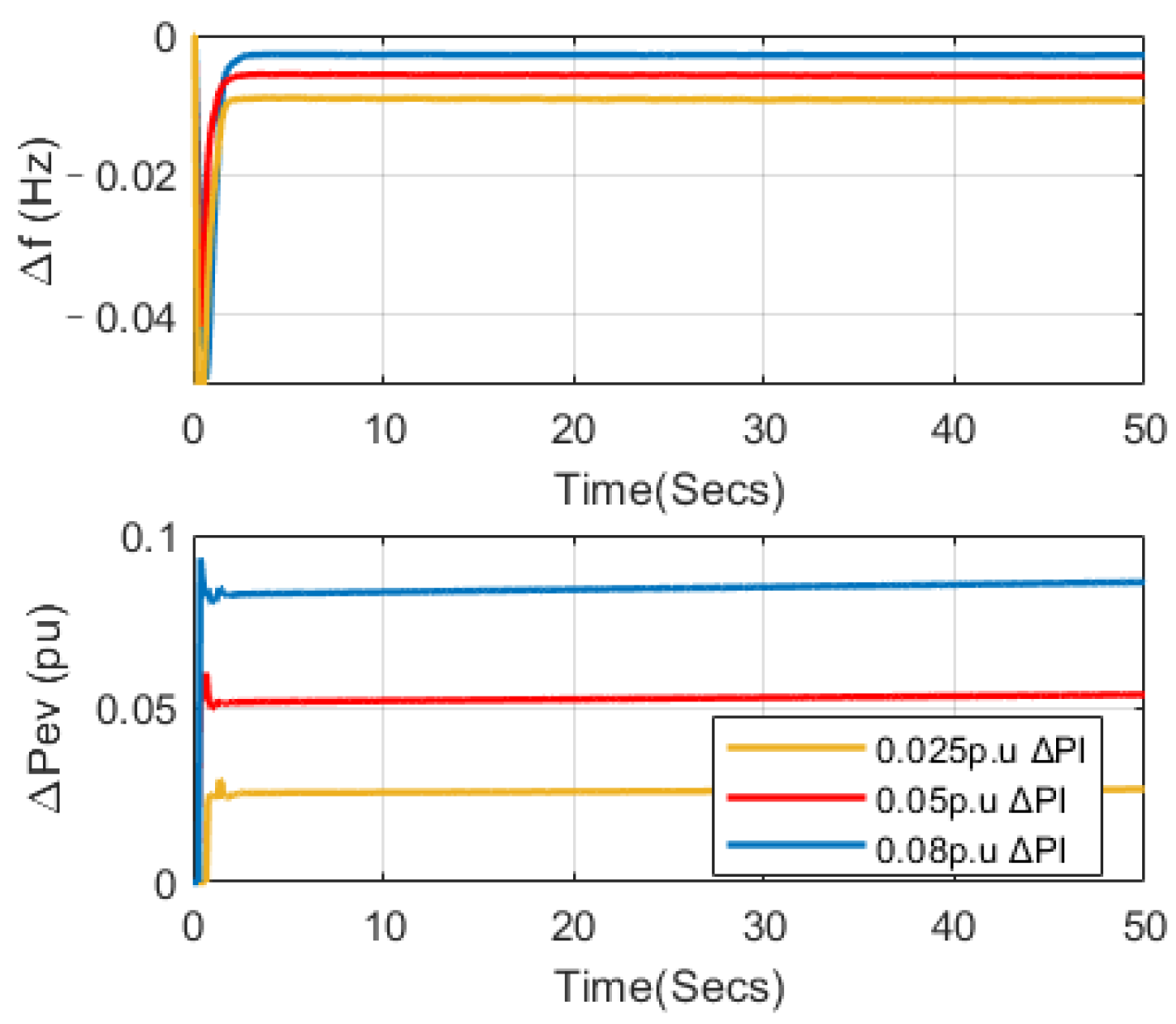
5.5. Dynamic Performance of a System with a Delay Compensation Strategy under Different Load Disturbances

To analyze the effectiveness of the proposed delay compensation method, we apply different interference powers to the same systems with 10% reduction in inertia. In this case, suppose that the step changes are equal to 0.025 p.u, 0.05 p.u, and 0.08 p.u, respectively. The total number of EVs integrated into the power system is 80,000, and the participation factor setting for EVs is the same as in Scenario 2 in Scenario 1. The comparison result is shown in Figure 13, and the maximum delay τ = 0.9 s. This can be clearly seen under the delay compensation strategy. Even as the disturbance increases, the system remains stable. Compared to Figure 9, the system does not oscillate and diverge at a step disturbance of 0.025 p.u. In the case of using the compensation method, the proposed coordinated control strategy has good performance and contributed to eliminating the adverse effects of communication delays.

6. Conclusions

This paper presents a control strategy for the frequency response of EV participation based on model predictive control. The proposed delay compensation strategy mainly includes two aspects: because the communication delay will affect the demand response of power system frequency modulation, the model predictive control is used to design the frequency response model controller of an electric vehicle and establish the frequency modulation model of a power system with an electric vehicle, and the compensation strategy based on MPC is used to reduce the impact in the process of frequency control. By establishing the selection rules of control signals, the multi-step control signals are dynamically adjusted in the rolling optimization process of the prediction model to form a delay compensation mechanism considering delay and packet loss. Simulation results show that EVs are effective in improving frequency stability under different participation factors. The comparison of simulation experiments demonstrates that the proposed compensation control strategy also has superior performance in time-varying communication delay compensation compared to other control strategies. As a mobile energy storage unit, an electric vehicle needs to consider its mobile characteristics, energy storage status, and owner’s intention in the process of frequency modulation. How to optimize the management of electric vehicle clusters and improve the willingness of vehicle owners to participate in grid interaction are the focus of future research.

Author Contributions

Conceptualization, F.Y., W.H. and X.Z.; Data curation, Z.Y., F.Y. and Z.Z.; Formal analysis, Z.Y., F.Y. and Z.Z.; Funding acquisition, Z.Y., F.Y. and W.H.; Investigation, Z.Y., Z.Z. and X.Z.; Methodology, Z.Y., W.H. and X.Z.; Project administration, Z.Y., F.Y. and W.H.; Resources, Z.Y. and W.H.; Software, Z.Z. and X.Z.; Supervision, Z.Y., F.Y. and W.H.; Validation, Z.Y., F.Y. and W.H.; Visualization, Z.Y., F.Y. and W.H.; Writing—original draft, Z.Z. and X.Z. All authors have read and agreed to the published version of the manuscript.

Funding

This research was sponsored by State Grid Corporation of China Headquarters Science and Technology Project, project number 5400-202122147A-0-0-00.

Conflicts of Interest

The authors declare no conflict of interest.

References

  1. Barreto, R.; Faria, P.; Vale, Z. Electric Mobility. An Overview of the Main Aspects Related to the Smart Grid. Electronics 2022, 11, 1311. [Google Scholar] [CrossRef]
  2. Smil, V. Decarbonization Algebra: The COP26 Calls for Impossibly Steep Cuts in Carbon Emissions: Numbers Don’t Lie. IEEE Spectr. 2022, 59, 20–21. [Google Scholar] [CrossRef]
  3. Nana, O. Bonsu. Towards a circular and low-carbon economy: Insights from the transitioning to electric vehicles and net zero economy. J. Clean. Prod. 2020, 256, 120659. [Google Scholar]
  4. Antoniadou-Plytaria, K.; Steen, D.; Carlson, O.; Mohandes, B.; Ghazvini, M.A.F. Scenario-based Stochastic Optimization for Energy and Flexibility Dispatch of a Microgrid. IEEE Trans. Smart Grid 2022. [Google Scholar] [CrossRef]
  5. Kroposki, B. Integrating high levels of variable renewable energy into electric power systems. J. Mod. Power Syst. Clean Energy 2017, 5, 831–837. [Google Scholar] [CrossRef] [Green Version]
  6. Amamra, S.-A.; Marco, J. Vehicle-to-Grid Aggregator to Support Power Grid and Reduce Electric Vehicle Charging Cost. IEEE Access 2019, 7, 178528–178538. [Google Scholar] [CrossRef]
  7. Liu, S.; Zhang, H.; Yang, J. Model Switching Frequency of Electrohydraulic-Power-Coupled Electric Vehicles with Different Delay Control Times. Electronics 2022, 11, 1299. [Google Scholar] [CrossRef]
  8. Zhang, C.-K.; Jiang, L.; Wu, Q.H.; He, Y.; Wu, M. Delay-Dependent Robust Load Frequency Control for Time Delay Power Systems. IEEE Trans. Power Syst. 2013, 28, 2192–2201. [Google Scholar] [CrossRef]
  9. Liu, F.; Li, Y.; Cao, Y.; She, J.; Wu, M. A Two-Layer Active Disturbance Rejection Controller Design for Load Frequency Control of Interconnected Power System. IEEE Trans. Power Syst. 2016, 31, 3320–3321. [Google Scholar] [CrossRef]
  10. Jin, L.; Zhang, C.-K.; He, Y.; Jiang, L.; Wu, M. Delay-Dependent Stability Analysis of Multi-Area Load Frequency Control with Enhanced Accuracy and Computation Efficiency. IEEE Trans. Power Syst. 2019, 34, 3687–3696. [Google Scholar] [CrossRef]
  11. Rehmani, M.H.; Reisslein, M.; Rachedi, A.; Erol-Kantarci, M.; Radenkovic, M. Integrating Renewable Energy Resources into the Smart Grid: Recent Developments in Information and Communication Technologies. IEEE Trans. Ind. Inform. 2018, 14, 2814–2825. [Google Scholar] [CrossRef]
  12. Alam, S.; Al-Ismail, F.S.; Salem, A.; Abido, M.A. High-Level Penetration of Renewable Energy Sources into Grid Utility: Challenges and Solutions. IEEE Access 2020, 8, 190277–190299. [Google Scholar] [CrossRef]
  13. Cao, Y.; Zhong, Y.; Peng, X.; Pan, S. Energy Efficiency Maximization for Hybrid-Powered 5G Networks with Energy Cooperation. Electronics 2022, 11, 1605. [Google Scholar] [CrossRef]
  14. Ko, K.S.; Sung, D.K. The Effect of EV Aggregators with Time-Varying Delays on the Stability of a Load Frequency Control System. IEEE Trans. Power Syst. 2018, 33, 669–680. [Google Scholar] [CrossRef]
  15. Huang, C.; Yue, D.; Xie, X.; Xie, J. Anti-Windup Load Frequency Controller Design for Multi-Area Power System with Generation Rate Constraint. Energies 2016, 9, 330. [Google Scholar] [CrossRef]
  16. Guille, C.; Gross, G. A conceptual framework for the(V2G) implementation. Energy Policy 2009, 11, 4379–4390. [Google Scholar] [CrossRef]
  17. Larsen, E.; Chandrashekhara, D.K.; Ostergard, J. Electric Vehicles for Improved Operation of Power Systems with High Wind Power Penetration. In Proceedings of the Energy 2030 Conference, Atlanta, GA, USA, 17–18 November 2008; pp. 1–6. [Google Scholar]
  18. Medina, J.; Muller, N.; Roytelman, I. Demand response and distribution grid operations: Opportunities and challenges. IEEE Trans. Smart Grid 2010, 1, 193–198. [Google Scholar] [CrossRef]
  19. Li, J.; Ai, X.; Hu, J. Supple-mentary Frequency Regulation Strategy Considering Electric Vehicles. In Proceedings of the 2018 2nd IEEE Conference on Energy Internet and Energy System Integration (EI2), Beijing, China, 10–22 October 2018; pp. 1–9. [Google Scholar]
  20. Annamraju, A.; Nandiraju, S. Coordinated control of conventional power sources and PHEVs using jaya algorithm optimized PID controller for frequency control of a renewable penetrated power system. Prot. Control Mod. Power Syst. 2019, 4, 343–355. [Google Scholar] [CrossRef] [Green Version]
  21. Wu, Y.; Yang, W.; Hu, Y.; Dzung, P.Q. Frequency Regulation at a Wind Farm Using Time-Varying Inertia and Droop Controls. IEEE Trans. Ind. Appl. 2019, 55, 213–224. [Google Scholar] [CrossRef]
  22. Zhong, J.; He, L.; Li, C.; Cao, Y.; Wang, J.; Fang, B.; Zeng, L.; Xiao, G. Coordinated control for large-scale EV charging facilities and energy storage devices participating in frequency regulation. Appl. Energy 2014, 123, 253–262. [Google Scholar] [CrossRef]
  23. Fan, H.; Jiang, L.; Zhang, C.K.; Mao, C.X. Frequency regulation of multi-area power systems with plug-in electric vehicles considering communication delays. IET Gener. Transm. Distrib. 2016, 14, 3481–3491. [Google Scholar] [CrossRef] [Green Version]
  24. Zhao, N.; Gorbachev, S.; Yue, D.; Kuzin, V.; Dou, C.; Zhou, X.; Dai, J. Model predictive based frequency control of power system incorporating air-conditioning loads with communication delay. Int. J. Electr. Power Energy Syst. 2022, 138, 107856. [Google Scholar] [CrossRef]
  25. Peng, C.; Zhang, J. Delay-distribution-dependent load frequency control of power systems with probabilistic interval delays. IEEE Trans. Power Syst. 2015, 4, 3309–3331. [Google Scholar] [CrossRef]
  26. Ahmed, M.; Zheng, Y.; Amine, A.; Fathiannasab, H.; Chen, Z.W. The role of artificial intelligence in the mass adoption of electric vehicles. Joule 2021, 5, 2296–2322. [Google Scholar] [CrossRef]
Figure 1. Frequency regulation frame for electric vehicles based on MPC.
Electronics 11 02341 g001
Figure 2. MPC algorithm control flowchart.
Electronics 11 02341 g002
Figure 3. Primary electric vehicle frequency regulation control model.
Electronics 11 02341 g003
Figure 4. LFC–EVs model for frequency response.
Electronics 11 02341 g004
Figure 5. Comparison of the system frequency response contributed by changing the EVs.
Electronics 11 02341 g005
Figure 6. A comparison of the generator’s and EVs’ power output.
Electronics 11 02341 g006
Figure 7. Frequency response of EVs under different communication delays.
Electronics 11 02341 g007
Figure 8. τ = 0.2 s system dynamic response with or without predictive compensation.
Electronics 11 02341 g008
Figure 9. τ = 0.9 s system dynamic response with or without predictive compensation.
Electronics 11 02341 g009
Figure 10. τ max = 0.2 s with or without predictive compensation of the system dynamic response.
Electronics 11 02341 g010
Figure 11. τ max = 0.9 s with or without predictive compensation of the system dynamic response.
Electronics 11 02341 g011
Figure 12. τ = 0.6 s system dynamic response for different prediction compensation.
Electronics 11 02341 g012
Figure 13. Dynamic response of the system under different load disturbances.
Electronics 11 02341 g013
Publisher’s Note: MDPI stays neutral with regard to jurisdictional claims in published maps and institutional affiliations.

