1. Introduction
Cloud computing applications and data center networks have many tussles, including (1) Application latency vs. network bandwidth. Cloud computing applications expect to transmit data quickly, and the underlying network devices take the way of storage-forward, so the transmission control protocol usually determines the bottleneck link according to whether the packet is lost or not. At this time, the latency of packet queues has already increased greatly. (2) The application asymmetry vs. network symmetry. The roles of compute nodes in the process of applications are not equivalent, and the bandwidth and volume are also different. However, the data center network always provides a symmetrical forwarding path. (3) The cross-border of application vs. hierarchical level of the network. A scalable data center network is built in a hierarchical way based on network equipment. However, the applications, which are distributed in different racks, communicate across multiple levels of networks. As cloud computing applications continue to enrich, data center network traffic is growing and unpredictable, which brings greater challenges to the design of network topology and transmission control.
The extension of the data center network has a variety of methods:
- (a)
Isomorphic extension. To support the continuous expansion of the data center scale, VL2 [
1], Portland [
2], Fat-tree [
3], and other network topologies are proposed, mainly with hierarchical stacking of the same type of network equipment to build high-performance networks. The network has the determined convergence ratio of the upper and downward link in the design, which is scalable and extensible.
- (b)
Heterogeneous expansion. A variety of communication technologies are used to construct heterogeneous network topology, and minimal changes to the existing network infrastructure are made through the auxiliary links to optimize the network. Due to the dynamics of the network hotspot, a new link is established reactively. ProjecToR [
4], Helios [
5], Modria, and other methods mainly use free space optical communication. Three-dimensional Beamforming, diamond, and other methods mainly use wireless technology.
- (c)
Reconfiguration. To make changes to the network infrastructure as small as possible, dynamically reconfiguring the original links of the data center network is proposed to meet the requirements of applications, such as Microsoft’s Larry architecture [
6], in which a circuit switching chip (ASIC) is adopted to connect Tor switches in the adjacent rack and converged switches. By controlling the connection of circuit switch ports, the Tor switch could take the uplink of other Tor switches to realize the uplink sharing between adjacent racks, which relieves network congestion.
The scale of cloud data center networks and the number of virtual machine nodes are continuing to increase, and east-west traffic is also growing rapidly. By the isomorphic extended mode, the layered architecture of the network inevitably makes hotspots at aggregation links. In addition, the application is more diversified, and the tidal phenomenon of hot spots in the network is becoming more and more difficult to predict. In heterogeneous expansion mode, the network topology changes dynamically, which delays the convergence of data center network routing. In the reconfiguration mode, the circuit switching is used to reconnect Tor switches with convergent switches, which also changes the network topology, brings the routing oscillation, and causes the routing convergence.
Facing the hotspot problem in data center networks, we propose a stratospheric network to alleviate network congestion. It dynamically establishes a VCS module between multiple Tor switches and provides a direct path for Tor communication, which can exchange packets directly and share uplinks to accelerate the transmission of east-west traffic. VCS modules in Tor switches are synchronized in the whole network and realize the virtual circuit based on time slots, in which packets are fragmented into cells and transmitted through the multi-channels of the multi-Path. The method could realize the communication of inter-racks, and could share the uplink. VCS in Tor switches are interconnected and structurally stable by chord-like. The link is not reconnected, so there is no delay, such as the link establishment, and the network topology is stable. The controller collects the user’s requirements of bandwidth and allocates the virtual circuit and time slots. Cells are extracted based on the preamble and forwarded by the VCS at the specified time slot.
2. Related Work
2.1. Circuit Switching
In circuit switching, an actual dedicated, end-to-end physical path should be established between the two communicating parties before data exchange.
Figure 1 shows the whole process of circuit switching, including three parts: line establishment before transmission, data transmission during transmission, and line release after transmission [
7]. The transmission delay of circuit switching is small, which is real-time. In addition, the transmission reliability of circuit switching is high, and there will be no out-of-order packets. However, circuit switching has low link utilization and is not flexible.
In order to meet the different bandwidth requirements of different applications, multi-rate circuit switching has emerged, which has multiple rate types. Fast circuit switching allocates bandwidth and related resources only when information is to be transmitted to overcome the shortcoming of the fixed bandwidth of circuit switching, which improves bandwidth utilization.
2.2. Packet Switching
Both packet switching and message switching belong to store-and-forward switching. Data is stored at the path node and then forwarded, which improves the utilization rate of the communication link. Among them, the message switching [
8] regards the entire message as the unit of storage and forwarding, which may cause a large delay. Packet switching divides the information to be transmitted into several packets as the unit, and the delay is shorter than that of packet switching.
Figure 2 shows the process of packet switching. It can be used in Ethernet [
9,
10] and optical networks [
11,
12,
13]. According to different transmission protocols and transmission paths, packet switching can be divided into datagram packet switching and virtual circuit packet switching.
Datagram packet switching [
14] uses each datagram as a data transmission unit and performs processing procedures such as path selection independently. A variety of routing protocols and forwarding technologies are used to support datagram packet switching and improve datagram forwarding speed, such as EGP, IGP, and so on.
Virtual circuit packet switching [
15] combines circuit switching with packet switching to build connections between sender and receiver before communicating. Each node in the connection has a data buffer, which performs output queuing and port forwarding according to the direction of the connection and the received packets.
The X.25 protocol [
16] is used for data services. It provides end-to-end confirmation and has certain reliability, but the confirmation and error control of each node will cause unnecessary delays. Frame Relay is an optimization technology of X.25. It uses the frame as a unit to transmit data, which shortens the transmission delay and has a low overhead. ATM (Asynchronous Transfer Mode) [
17,
18] technique uses cells as the unit of packet switching and adopts asynchronous time division multiplexing for transmission. ATM has scalability and low latency.
2.3. Next Generation Datacenter Architecture
Google unveils the datacenter architecture Aquila [
19], which is a unified low-latency fabric for data center networks. Aquila is a meaningful exploration of a unified data center fabric supporting both traditional data center traffic as well as ultra-low latency traffic, such as Remote Memory Access (RMA). It achieves under ~40 µs tail fabric RTT for IP traffic and sub-10 µs RMA latency on a clique-scale.
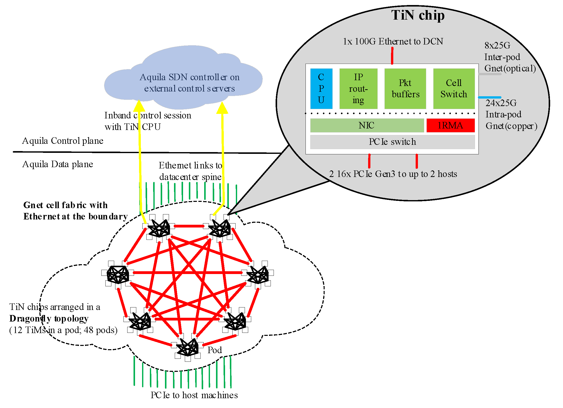
Google’s researchers designed a new Layer 2 cell-based protocol, i.e., GNet, an integrated switch, and a custom ASIC with low-latency Remote Memory Access (RMA), as shown in
Figure 3. Aquila networks are built from individual silicon components that serve as both NIC and a portion of the traditional Top of Rack (ToR) switch. GNet uses shallow-buffed Cell-switching in which cells are fixed-size, i.e., 160 Byte data units, and virtual channels are designed for QoS and Deadlock Avoidance. GNet also uses credit-based flow control at Cell-level to achieve near-lossless.
3. Prototype Design
Tor switches in racks are connected to aggregation switches. Tor switches in the access layer forward packets through the intermediate nodes of upper aggregation switches, which is called the troposphere network. Ports of aggregation switches are limited, so their ports are typically divided among lower-level Tor switches in racks, which is a hierarchical structure and constrains the bandwidth of east-west traffic in cloud computing. In addition, in the processing of applications, there are also problems such as uneven utilization of uplink of Tor switches in racks.
3.1. Principles of Stratospheric
Reconfigurable circuit switching alleviates the applications’ suffering from network congestions, but route oscillation can be introduced. Virtual circuit switching based on time division multiplexing of links is proposed to realize the direct exchange between Tor switches in adjacent racks.
As shown in
Figure 4, ToR switches are integrated with VCS modules through the special bridge port, and other Ethernet ports of Tor switches are still connected to the upper-level aggregation switches. VCS ports are connected to ports of other VCS modules in other Tor switches. The cluster of VCS modules is connected and synchronized, which enables Tor switches to communicate directly. VCS forwards partial data between multiple Tor switches and constitutes a fast virtual circuit switching network in the access layer, which is called the stratosphere network. Tor switches could use the idle uplink of other Tor switches to scatter traffics through the stratosphere, which acts as a relay for the Tor uplink to relieve the hotspot in a data center network.
3.1.1. Virtual Circuit Switching
In the stratospheric, the links are divided into multiple time slots to form virtual channels, which are assigned different priorities, so applications of different priority are mapped to different virtual channels. Under the configuration of the controller, packets from multiple input ports could be switched to different virtual channels in the same or different output ports.
VCS adopts time-division multiplexing to schedule multiple virtual channels on the same physical link, and each virtual channel occupies the same amount of the time slot. The first time slot is named the first virtual channel, and the second time slot is named the second virtual channel, and so on. For the specification of IETF DiffServ, the link is also divided into eight virtual channels, and the bandwidth of each virtual channel is 1/8 of the link rate, which supports dynamic allocation based on the QoS of applications. VCS is configured by the controller, and the input port receives packets from different virtual channels, which are then switched to different virtual channels in different output ports based on forwarding rules.
Tor switches in adjacent racks are connected through virtual circuit channels, which enable Tor switches in multiple racks to communicate direct bypass aggregation switches. Packets could be forwarded by VCS to ToR switches in adjacent racks and then transmitted through their uplink, which enables multiple Tor switches to share the same uplink. The links between the VCS modules in different Tor switches are always connected, and there is no link re-setup for the whole data center network.
3.1.2. Cells of Ethernet Frames
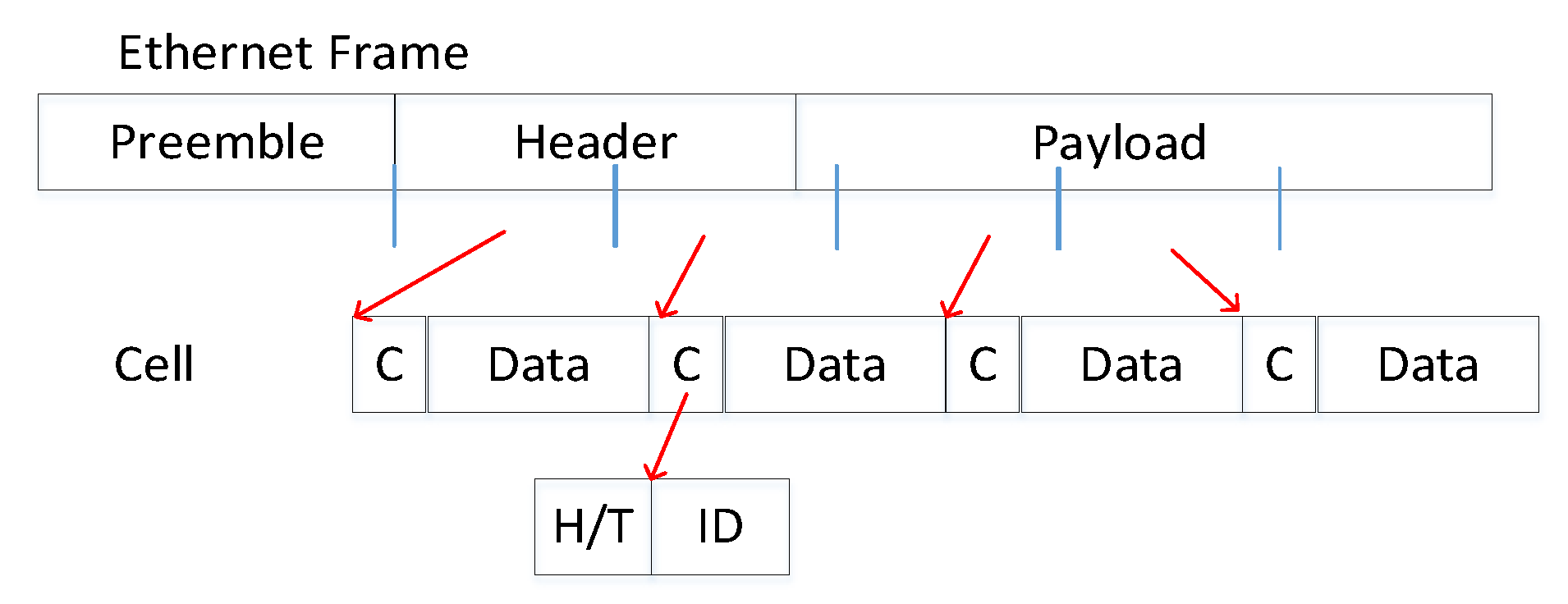
In the stratosphere, the bridge port of ToR (a dedicated internal port connected to VCS modules) receives Ethernet frames and splits them into fixed-size cells, as shown in
Figure 5. Cells of Ethernet frames are transmitted in the time slot corresponding to a virtual channel. The virtual channel ID is inserted into the cell header to identify the virtual channel.
Figure 6 shows the transmitting of cells. Cells are matched with the forwarding table to select the output port and channel, and different cells of the same packet are transmitted through the same virtual channel. The input port in the next VCS passively follows the virtual channel of upper nodes and parses the virtual channel ID in the cell header embedded by source nodes to identify the current virtual channel.
According to the rate limiting in the bridge port and the channel plan of the controller, no additional information to be notified to the network is required except for the channel ID, which is inserted in the header of the cell by the bridge port. Cells belonging to the same packet have the same channel ID, so they are forwarded on the same path. At the destination node, the cells are queued and then assembled when all of the cells have arrived. In the header of the cell, there is another flag to identify the first, middle, and last cells of the packet. After the packet is assembled completely, the CRC of the packet is computed and verified, and the packet can be dropped for CRC errors.
3.2. Processing of VCS Modules
3.2.1. Pseudo-Synchronization Transfer
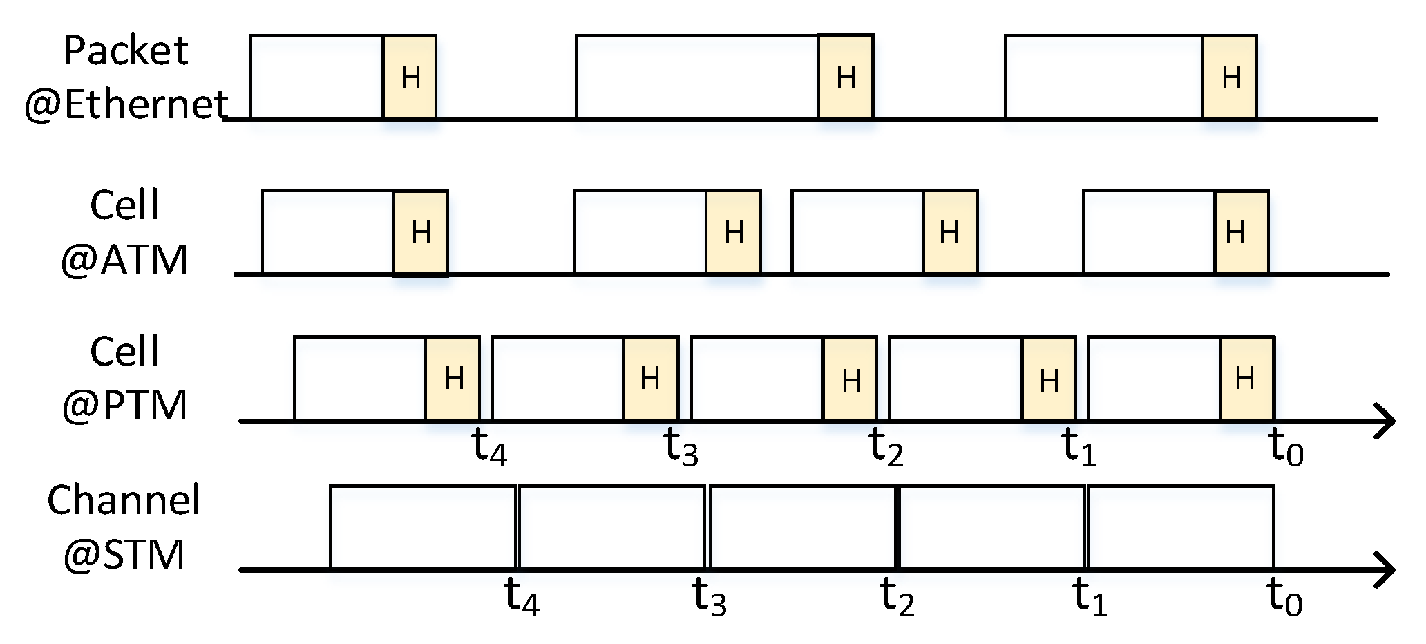
In a circuit switch, switching nodes should be synchronized to each other, so output ports in upstream nodes are synchronized to input ports in downstream nodes. If there is little difference in the time of transmitting and receiving, signal or data may be lost. The synchronization is very strict and hard to be implemented at a high-speed link. VCS modules in the stratosphere are also synchronized to each other. The output port transmits cells at the specified time of the channel, but the input port can identify the cell based on its preamble rather than the time it was received.
The stratosphere is a pseudo-synchronization transfer mode, in which the transmission is different from STM and ATM. VCS modules could scramble and parse the preamble and the header of cells, which could support the dynamical routing.
3.2.2. Network Congestion Controlling
The virtual channel of VCS is fixed, and the rate is also determined. The rate of data is specified and controlled to prevent network congestion.
Rate limit. Cells of packets are transmitted by the source node at the rate assigned in QoS SLA, and the bridge port of source nodes controls the rate based on the token bucket. If the quota is exceeded, cells are cached in port queues of the node. The rate is the bandwidth of a virtual channel because it is transmitted in a virtual link. Packets could be dispatched in multiple virtual links, so the rate is the sum of multiple virtual channels.
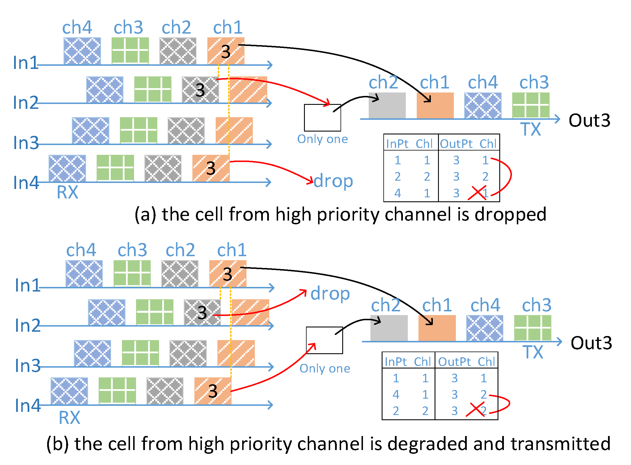
Virtual channel conflicts. The output ports of VCS are synchronized and divided into virtual channels according to time slots. Based on the configuration of the controller, cells received from input ports are forwarded to different virtual channels in different or the same output ports. Due to different transmission delays, packet cells from different input ports may cause overlap in the same output port, which creates a conflict between virtual channels. In output ports of VCS modules, cell-level storage is set up to cache one cell from the other virtual channel.
As illustrated in
Figure 7, cell x of channel 1 from input port 1 and cell y of channel 2 from input port 2, which are transmitted to different channels of the same port, are only overlapped. Cell x is transmitted normally, but cell y is cached. Cell x and cell z of channel 1 from input port 4, which are transmitted to the same channel and same port, are competition. Cell z is dropped to normal. With respect to priorities, cell z could be degraded and cached to be transmitted in the next slot, but cell y is dropped. Priorities are combined with time slots of ports, which provide adaptive forwarding to alleviate network congestion.
3.3. Management of VCS Modules
3.3.1. Topology of VCS Modules
Data centers consist of several rows, which hold many computer racks. VCS modules in racks could be interconnected only with others in the same row. In general, there are about ten racks in the row, and the number of ToR is also the same amount. In order to decrease the hop or the diameter of the stratosphere network to reduce the latency of the network, the stratosphere adopts a chord-like structure. The VCS modules are not only connected to VCSs in adjacent racks but are also connected to the VCSs with the hop number of two, four, eight, and so on, which are all power of two, as illustrated in
Figure 8. The controller could compute the routing based on the sequence number of the VCS module in the topology of the chord, and there is at least one intermediate node and at most two hops between each pair of two ToRs. For example, data is transmitted through Tor R1 and R11. The intermediate node of R9 is selected because the number 9 is at least 2^4 or greater. The ToR switches integrate with VCS modules, and the VCS modules are interconnected according to the Chord structure, which forms a direct switching network (stratosphere) under the ToR switches. To prevent congestion in the stratosphere network, the traffic forwarded from Tor R1 to R9 could not be more than 1/2 of the total amount, and from R1 to R5, it could not be more than 1/4 of the total amount, and so on, as illustrated in
Figure 9.
3.3.2. Out of Band Management
VCS modules are connected with ToR switches, so the controller of the data center network sends commands to the VCS through the ToR switches, which is out-of-band management. The commands are encapsulated in Openflow packets, and the target Tor switch receives and parses the command, which is relayed to the bridge port of the VCS. The bridge port parses the command and configures the VCS modules. On the contrary, the bridge port collects the statistics of the VCS, which are delivered to the controller through the ToR switch.
Via the out-of-band management, the controller could get the global view of Ethernet switches and virtual circuit switching networks. It manages the Ethernet switch and virtual circuit switch in the same way, which supports that the virtual circuit path and Ethernet path are configured in the unified mode.
3.3.3. Path Plan
The controller could take two ways to control the stratospheric network: the controller periodically collects buffers of uplink ports in Tor switches. When the utilization of the buffer exceeds a certain threshold, the path adjustment for high-priority traffic is made reactively. On the other hand, according to the requirement of applications, the configuration of the Ethernet switch and virtual circuit switching is made by the controller proactively.
Mode 1: The controller periodically collects the utilization of uplink ports of Tor switches to dispatch traffic among the Tor switches of adjacent racks. The EF traffic, AF traffic, and BE traffic are counted separately. When EF traffic exceeds a threshold and uplinks of Tors in adjacent racks are still idle, the EF traffic is migrated to the virtual circuit channel until its end, which could alleviate local hotspots of Tors. When the AF traffic exceeds the threshold and the virtual circuit channel also has an idle time slot, the AF is relayed to the virtual circuit channel. AF traffic is returned when AF traffic is less than the threshold.
Mode 2: The controller receives the transport request from source servers and assigns the virtual circuit channel and the Ethernet path. The controller configures the bandwidth and forwarding rules of the Ethernet switch and VCS according to the current switch state and user requirements. Depending on the traffic of the Tor switches in adjacent racks, the uplink bandwidth could be occupied by the traffic from neighbor Tor switches to prevent network congestion.
In mode 2, an interface between application/user and controller/network is required. The host–network interface is packet options defined in TCP/IP, and the manager-network interface is the protocol of SNMP proposed by IETF, as we know, which are all not suited for notifying the requirements of users. In the stratosphere, there are two means to provide the requirements. One is designing a new option of packets, in which the users’ requirement of bandwidth or latency is inserted. For the first hop of VCS modules, the bandwidth requirement in packets may not be stratified, which could induce dropping of packets, so it is only recommended in the unreliable communication of a single packet. The other way is that a dedicated API associated with sockets is provided for applications in the stratosphere, through which the requirements of users are transferred to the controller of the stratosphere before the communication.
4. Prototype of VCS
4.1. Designing and Implementation
In VCS, physical links are divided into virtual channels, and the Ethernet interface MAC should be modified, which requires a programmable network platform.
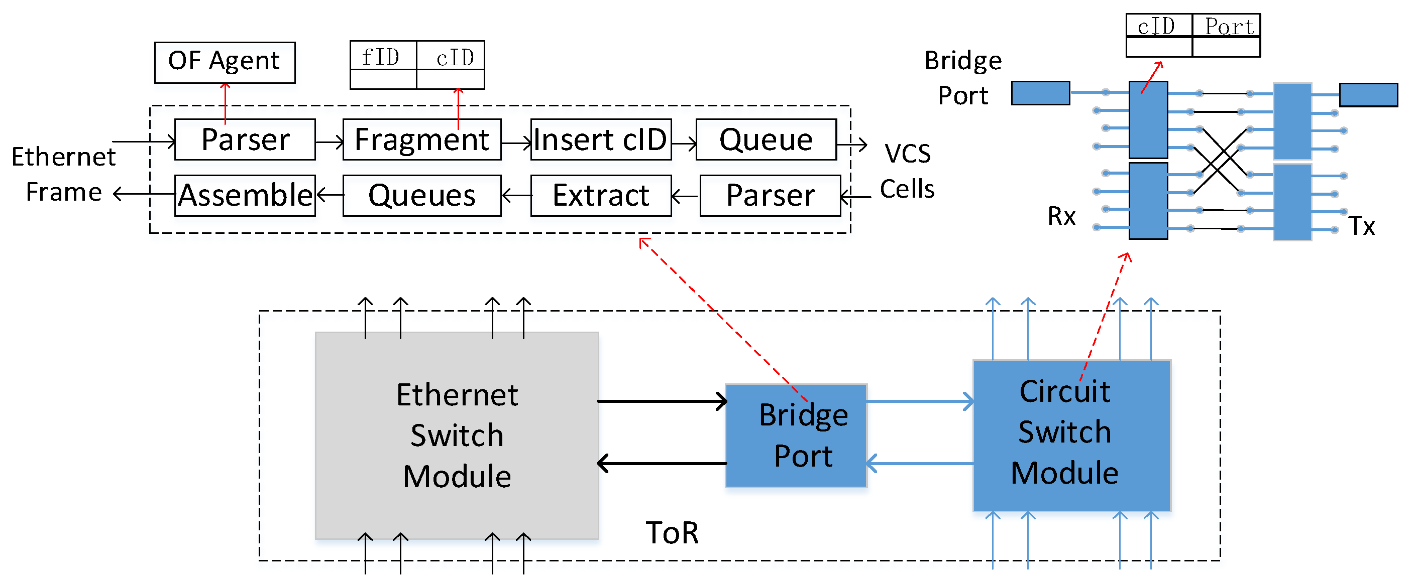
Figure 10 shows the implementation of a VCS prototype. The VCS module could be implemented based on the programmable hardware of FPGA or network processor, such as Huawei Switches based on ENP and the Rongteng switches based on NPS400. We built VCS modules of 8 × 40 GE from the basic circuit switching point based on FPGA (Xilinx Development Board).
The bridge port parse and lookup the target channel of the Ethernet frame based on FEC then fragments and inserts the channel ID. When receiving cells from input ports, the VCS forwarding engine extracts and looks up the virtual channel ID in the Cell header against the forwarding table and forwards it to the corresponding virtual channel in the destination output ports. At the present time, the functional verification has been completed and is ready to tape out in the way of the NPW at the 28 nm process. The initial assessment of power consumption is about 6 watts.
The bridge port of VCS modules fragments Ethernet frames, which are passed through 64/66 coding, while the input and output ports of VCS modules should not decode the payload. Interfaces of VCS modules are based on the native phy and transmit the raw data through the phy of FPGA, in which the signal to or from the channel is serialized or deserialized to reduce the frequency of the data.
4.2. Multi-Mode Forwarding
VCS modules could support a variety of switching modes:
(a) virtual circuit vs. virtual channel. Because the VCS modules cut Ethernet frames into cells, which are transmitted on the time slot of the virtual circuit. When VCS modules do not synchronize with each other, VCS descends and takes the storage-forwarding mode to realize the switching based on virtual circuit identification inserted in the preamble of cells, which is similar to ATM.
In a stratosphere network, which consisted of several numbers of Tors in the same row or in the same aggregated switch, VCS modules could synchronize and provide the synchronized transfer model. The channel and path could be configured proactively by the controller. Cells need not be parsed and are transmitted in the cut-through model at specific time slots directly, so the latency of the stratosphere is smaller and more determined than ATM.
(b) path vs. ID. The VCS module also supports the switching based on cell ID. When the bridge port of the source VCS module splits packets, the IP address of the end system can be mapped to the identity of cells, which is encapsulated into the cell header, so packets are forwarded flexibly based on the cell ID in the switching module.
In the mode, the stratosphere network is full adaptive routing, in which cells are cached and matched against the forwarding table to select the output port. VCS modules need not be synchronized, and paths or channels need not be configured ahead. Each cell has a fixed size of cell header and payload, which results in lower utilization than packet switching, while the latency of processing is fixed and small.
For the mode of virtual channel switching and cell switching, the latency of the stratospheric is smaller than Ethernet switching. VCS is suited for critical communication in the data center, such as parameter server or barrier, which is a supplement to Ethernet switching.
(c) unicast vs. multicast. VCS supports multicast forwarding, in which cells from one channel are forwarded to multiple channels, and a multicast group is built in the stratosphere to accelerate a large number of synchronous operations in high-performance computing. Compared with circuit switching, such as Larry, VCS could also support indirect switching between Tor switches of adjacent racks and convergent switches. For the topology of a chord, there are more than two paths of different hop and latency between the source and destination of Tor switches. Packets of applications are hashed among the multiple virtual links for load balancing.
5. Performance Analysis
In this section, the prototype system implementation of the stratospheric network is carried out on a Xilinx FPGA platform. First, the experimental environment is introduced, then the selection of relevant parameters is introduced, and finally, the performance evaluation of transmission delay and scalability is given.
5.1. The Test Environment
Figure 11 shows the test environment in which two Tor switches are connected to the aggregation switch and are integrated with VCS. VCS modules are connected directly to form the stratospheric network to enable the exchange between Tor switches. The IXIA (network tester) transmits packets to the source Tor switch, which is sliced by bridge ports and forwarded through the first hop and last hop VCS modules to the destination Tor switch; then, the network tester receives packets from the destination Tor switch (data flow 1). The main test tries to illustrate the affection of the network latency and the effective bandwidth crossing the virtual circuit switching, which is compared with the network delay and the link efficiency of the path between Tor switches via the aggregation switch.
5.2. Optimization of the Parameters
5.2.1. The Preamble
The preamble occupies multiple circles of the channel, which decreases the utilization of the link. The best and minimal sizes of the preamble are set. Due to the synchronization of VCS modules, the size of the preamble could be reduced based on the start time of the channel, which still supports the synchronization and identifies the first bit of cells. The variable sizes from 7 bytes to 1 byte are all tested. During the long-term testing, one byte of the preamble for cells is satisfied with the 40 G interface. The special char, 0 × 55, is selected as the preamble, which is the same as the preamble of the Ethernet frame and is not in 64/66 code.
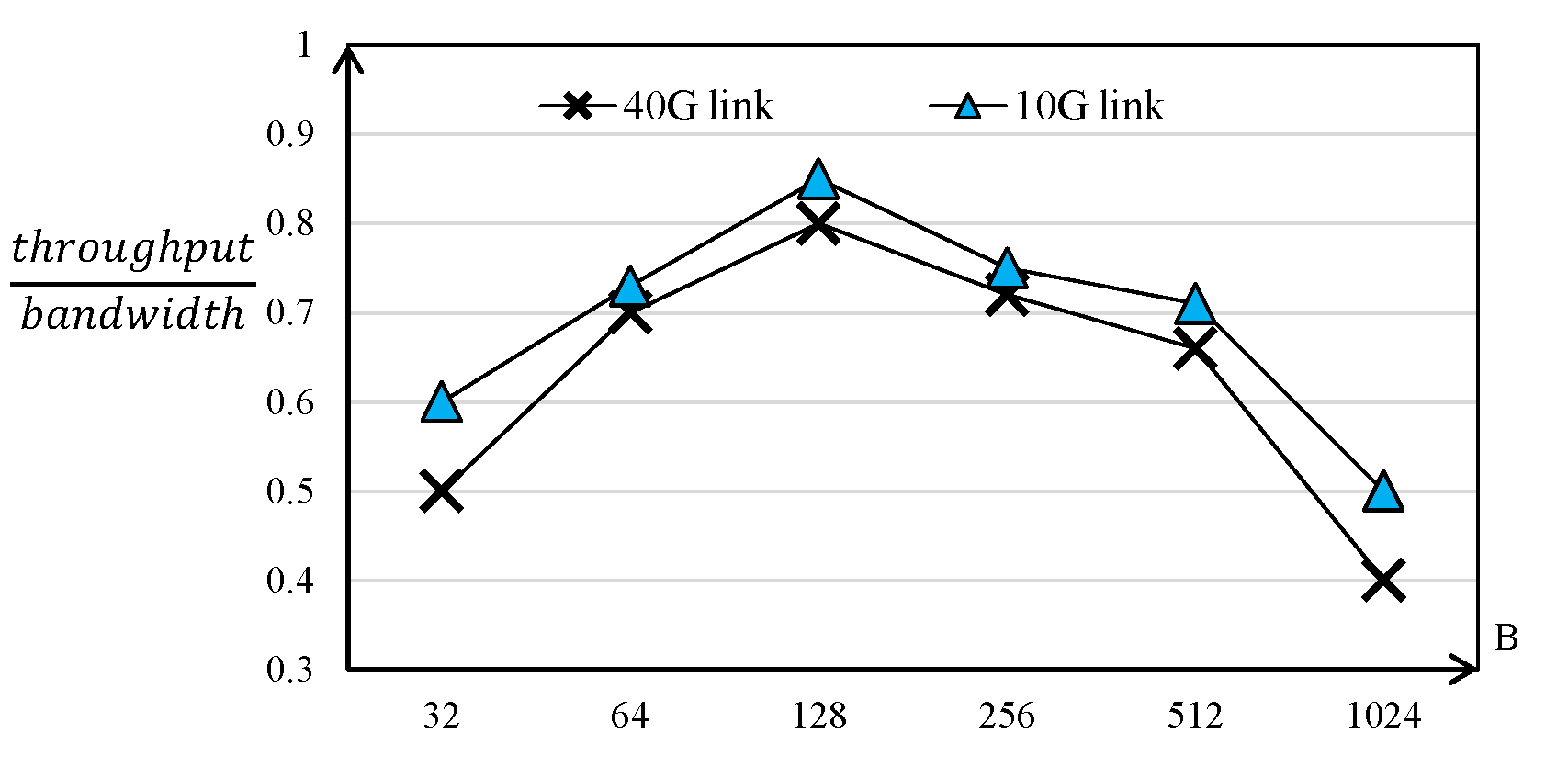
5.2.2. The Size of Cells
Increasing the size of cells could improve the utilization of the link due to the higher ratio of the header to the payload, while utilization of the link will decrease when it exceeds the threshold because of raising the unused data in one cell. Meanwhile, when the size of cells is increased, the delay of cells is also augmented. Several sizes of cells are tested under the minimal value of the preamble, and the result is in
Figure 12. We can conclude that the size of 128 bytes is the best size for cells.
All the parameters are tested and optimized for the 40 G link and 10 G link. For other links, the parameter should be re-tested and re-selected in future work.
5.3. Performance of Applications
5.3.1. The Latency of Processing
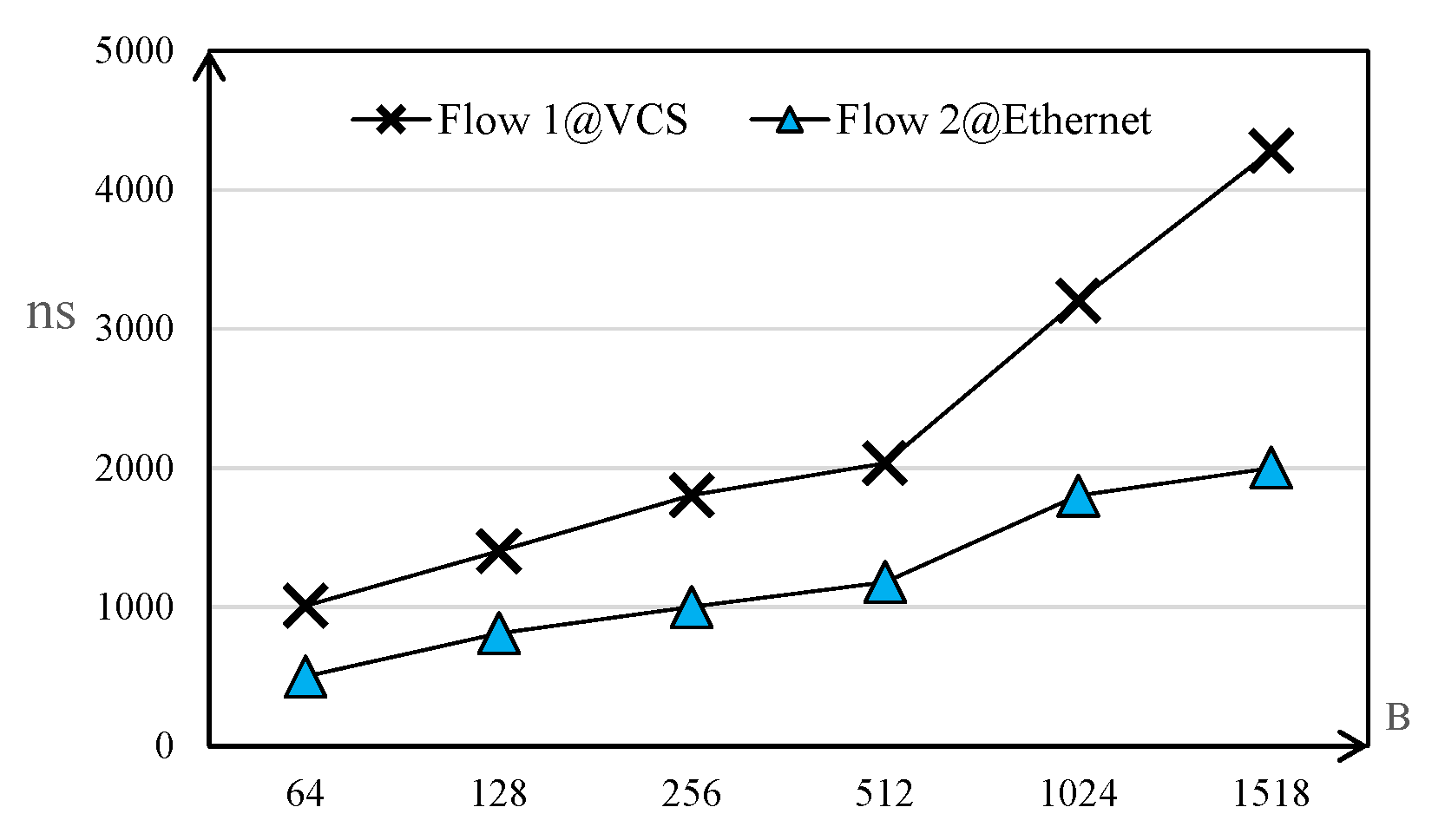
In the process that VCS is receiving cells, the channel of the input port receives the signal from SerDes, which is strung and decoded to recognize the virtual channel ID in the header of the cell. In the switching process, there are two levels of processing in virtual circuit switching, and each level processes six slots of the cell. In the prototype system based on Xilinx FPGA, the processing delay of the physical port is about 12 ns, and the virtual circuit switching modules run at 250 MHz (4 ns). Then, the switching delay is 2 × 6 × 4 = 48 ns, and theoretically, the delay is about 60 ns, which is smaller than the cut-through forwarding delay in a typical commercial switching chip. We also compare the flow completion time (FCT) for different sizes of flows in VCS and Ethernet, and
Figure 13 shows the result. We can conclude that VCS can reduce the FCT significantly.
5.3.2. Acceleration of the Parameter Server
A typical application of ML runs in the test network. The barrier latency of the parameter server is measured in the Ethernet network with the stratosphere network, and the results are shown in
Figure 14. The latency is deceased to 500 µs from 2 ms, which is measured in the Ethernet network without the support of the stratosphere network. The acceleration demonstrates the high efficiency of the transmission for the east-west traffic in the data center.
5.4. Scalability
VCS modules, which are connected to the Tor switch along with the same aggregation switches, and the stratosphere network provides the direct exchange for those Tor switches. When the number of connected Tor switches increases, the bandwidth of VCS modules becomes the bottleneck, which starts to constrain the acceleration for applications. Through the simulation, the total bandwidth of Tor uplinks is about 30 times that of the VCS bandwidth, which is about 16 Tor switches of 10 GE. The speedup reaches the maximal and begins to cut down. In the next step, the speed of the network interface would be promoted to 400 G, which could support expanding the scale of the stratosphere network.
6. Conclusions
To alleviate hotspots in the data center network, we propose a stratospheric network to alleviate network congestion. It dynamically establishes a VCS module between multiple Tor switches and provides a direct path for Tor communication, which can exchange packets directly and share uplinks to accelerate the transmission of east-west traffic. Under the management and configuration of the controller, the link in VCS is split into several channels based on time slots, and packets are fragmented and forwarded. Stratospheric network switches based on cells do not have the delay of processing, which are more efficient than Larry. The direct exchange speeds up the critical east-west traffic of applications. The main weak in stratospheric is that the virtual circuit is divided by the output ports according to the time slot. When the cells from different ports are forwarded to the virtual channels in the same port, they overlap and compete with each other. Because the time difference of the virtual channel does not exceed eight cells, stratospheric networks also need to supplement the cell-level cache to alleviate the problem of virtual circuit competition.

