Article

Coplanar Asymmetry Transformer Distributed Modeling for X-Band Drive Power Amplifier Design on GaN Process

1
Institute of Microelectronics, Chinese Academy of Sciences, Beijing 100029, China
2
University of Chinese Academy of Sciences, Beijing 101408, China
3
Beijing Key Laboratory of New Generation Communication RF Technology, Beijing 100029, China
*
Author to whom correspondence should be addressed.
Electronics 2022, 11(16), 2478; https://doi.org/10.3390/electronics11162478
Submission received: 13 June 2022 / Revised: 26 July 2022 / Accepted: 31 July 2022 / Published: 9 August 2022
(This article belongs to the Section Circuit and Signal Processing)

Abstract

:
In this paper, a methodology for designing a distributed model for coplanar asymmetry transformer on gallium nitride (GaN) process is proposed, which can accurately characterize the transformer’s feature up to a millimeter-wave band. The paper analyses a transformer-based matching circuit and proposes a practical transformer design procedure. A two stage, transformer matching based X-band power amplifier (PA) is reported here. Using the proposed transformer model and correlated transformer design procedure can sharply reduce schematic design period and optimum process time. The PA chip is designed on a 0.25 µm GaN technology process and occupies a 1.515 mm2 area. At a 28 V supply, the gain and output power of the PA reaches 15 dB and 29 dBm respectively, and the wideband matching transformer reaches 47.6% bandwidth. To the best of our knowledge, the distributed model for coplanar asymmetry transformer and transformer-based X-band MMIC PA on GaN process in this work is the first case among the reported papers.

1. Introduction

In recent years, the transformer has been widely used in Radio Frequency (RF)/mm Wave circuit design [1,2,3,4,5,6], such as the Voltage Control Oscillator (VCO) [7], frequency multiplier, mixer, low noise amplifier (LNA) [8], and PA [9,10,11]. Essentially, the on-chip transformer is a high-order LC network that composes prime/secondary winding and parasite capacitance. Its easy-to-deploy layout enables designers to have a high degree of design freedom, and far more adjustable parameters [12], which are favorable to wideband PA design. The transformer has the capability of low-loss AC coupling, impedance matching/transformation, and power combining [6,13]. Especially, transformer matching can absorb device output capacitance into the matching network and is widely used as broadband CMOS PA design [14,15,16]. Instead of CMOS process, on-chip transformer is also be integrated on SiGe [9], GaAs [11], and BiCMOS [17,18] process chips.
Electronic Design Automation (EDA) platform Electromagnetic (EM) simulation tools provided us with a way to build transformer model, thus the designer had a higher degree of freedom for designing on-chip transformers, and no longer relayed on the foundry provided model. Generally, there are two kinds of modeling methods for on-chip transformers: lumped element modeling [10], and distributed modeling [19,20]. The lumped element modeling method explores transformer inherent parasitic and loss mechanism, using the lumped element to build the transformer model; the famous symmetric 2π-model [10] is the most representative one. However, lumped element modeling heavily relies on simulation results and embodies numerous parameters that need to be determined, which makes the modeling process so complex, and the distributed modeling method views the transformer as the coupling transmission line. Thus, to be able to obtain the complete characteristic of the transformer, it has been widely studied in recent years. In this work, we also use the distributed modeling method and an accurate distributed model for a coplane asymmetrical transformer on GaN process is built.
Based on the CMOS process, several sets of research for on-chip transformer designing have been proposed, such as Inductively Coupled Resonators (ICR) design flow [21], transformer-based matching networks (TMN) synthesizing method [22], magnetically coupled resonator (MCR) design method [12], and coupled line based electric (capacitive) couplings [19]. In this work we also provide a simplified transformer design procedure for GaN process.
However, previous research has rarely concerned transformer performance on MMIC design and lacks corresponding modeling, designing methodology. The normal method to model on-chip transformers in Radio Frequency (RF) is the use of S-parameters, obtained from ElectroMagnetic (EM) simulation. The drawback of such an approach is that EM simulation can be time-consuming and the simulated S-parameters may cause a divergence problem in the transient simulation of the circuits [10]. Moreover, the distributed modeling [10,17,19,20] method for coplanar asymmetry transformer has not been studied yet. The asymmetric coupling structure means it cannot be analyzed through the traditional even–odd mode method [23], and wideband design requirements worsen the case. Additionally, because of wavelength and device scale, transformer matching has rarely been used in microwave frequency band RF circuits. Therefore, the urgency for developing a new model for asymmetry coplanar transformer within microwave band and corresponding design method on MMIC cannot be ignored.
This paper proposes a distributed model for an asymmetric coplanar transformer at microwave band and discusses the transformer impedance matching mechanism for PA design. All the design methods and experiment results are carried out on MMIC GaN technology process. The paper is organized as follows: Section 2 discusses transformer design process parameters and the influence on the transformer performance. Section 3 describes the proposed modeling method for asymmetric coplanar transformer and equivalent distributed model. The transformer design procedure and port impedance characteristics are illustrated in Section 4. In Section 5, a two-stage transformer matching power amplifier design on 0.25 µm GaN process is presented. By using the proposed analytical method and the transformer model, the designed PA achieves ideal performance. The conclusion is set in the last part, Section 6.

2. Transformer Design Process Comparison

The IC technology process decides a fabricated inductor or transformer’s performance. The transformer-related technology process parameters include top metal layer thickness, metal conductance, minimum metal space, the metal layers’ distance towards the substrate, substrate dielectric constant, and so on. Because of the parasitics and different loss mechanisms, the impedance transformation ratio is highly frequency and size-dependent and deviates from its ideal value of 1, even for a 1:1 transformer [10]. Although some of the parameters are predefined in the technology process, it provides us with a reference for transformer design.

2.1. Process Parameters’ Influence to On-Chip Transformer

Table 1 lists major RF technology process parameters comparisons. The advanced smaller feature size CMOS process has more metal layers and thicker top metal, and the top metal conductance significantly improves to 5.816 × 10⁷ S/m in the TSMC 0.13 µm CMOS process. From TSMC 0.25 µm to 0.13 µm CMOS process, the metal layers are added from 5 to 8. While III-V compound processes like GaAs and GaN listed in this Table have two metal layers, and comparatively larger metal conductance and layer space, in 0.25 µm GaN process, top metal thickness reaches 4 µm, which is the thickest among the listed processes. Using the thicker metal layer to design an on-chip transformer can effectively increase coupling coefficient and reduce the loss, and it also helps to enlarge transformer self-resonate frequency (fsrf), which is of great use in practical design.
Thus, compared to CMOS technology, GaN process has a thicker top metal layer and larger metal conductance, but its metal layers are closer to the substrate, which will suffer more substrate loss. The comparatively larger minimum metal layer space on the GaN process, 6 µm for MET2 layer, will constrain the designed coplanar transformer coupling coefficient to some extent.

2.2. Transformer Design on GaN Process

Figure 1a reveals the simplified 0.25 µm-GaN technology process cross-section view. Metal layers, MET1 and MET2, have the same conductance but different thickness. MET2 is 4 µm thick, and 1.622 µm away from SiC subtract, while MET1 is only 1.1 µm thick and 0.252 µm to the subtract. The substrate and floating shields take up 100 µm thickness. Both MET1 and MET2 layers can be used for designing the passive element on MMIC. However, MET2 is much thicker and further to the substrate, which makes it more favorable. In Figure 1c, a vertical design on this process is shown that uses the MET1 and MET2 vertical structure to form a coupling structure. Due to the narrow space between the two metal layers—0.272 µm for this GaN process as we can see in Figure 1a—the practical vertical transformer has larger coupling coefficient and parasite capacitance and these parameters are hardly adjustable, which greatly restricts practical transformer design freedom on 0.25 µm-GaN process. In Figure 1d, an octagonal coplanar transformer designed on MET2 is shown, and MET1 is used for cross-layer interconnection. w1/w2 represent primary/secondary winding metal line width, or trace width, d represents transformer inner diameter and s represents space between the primary and secondary winding. Notice that the trace width, w1/w2, for primary and secondary winding is asymmetric. This asymmetric physical structure makes coupling effect analyzing become much more complex, and different trace width at primary/secondary winding can be used for adjusting equivalent inductance. Ports 3/6 are central-tap, normally used for device biasing. Figure 1b shows the proposed distributed model for the coplanar transformer that is based on asymmetric parallel coupling transmission line models, CLA and CLB. Ports numbers in Figure 1b,d are equivalent. Several experiment results are shown in the following passages, to reveal the transformer’s performance on GaN process.

2.2.1. Vertical and Coplanar Transformer’s Feature on GaN Process

In Figure 1c, the transformer has a vertical coupling structure. MET1 and MET2 are drawn in the same shape. In this case, MET2 is for transformer primary winding and MET1 is for the secondary. The vertical transformer has higher coupling coefficient, larger equivalent capacitance, and lower fsrf, while the coplanar transformer is opposite. An experiment was set to illustrate this trend.
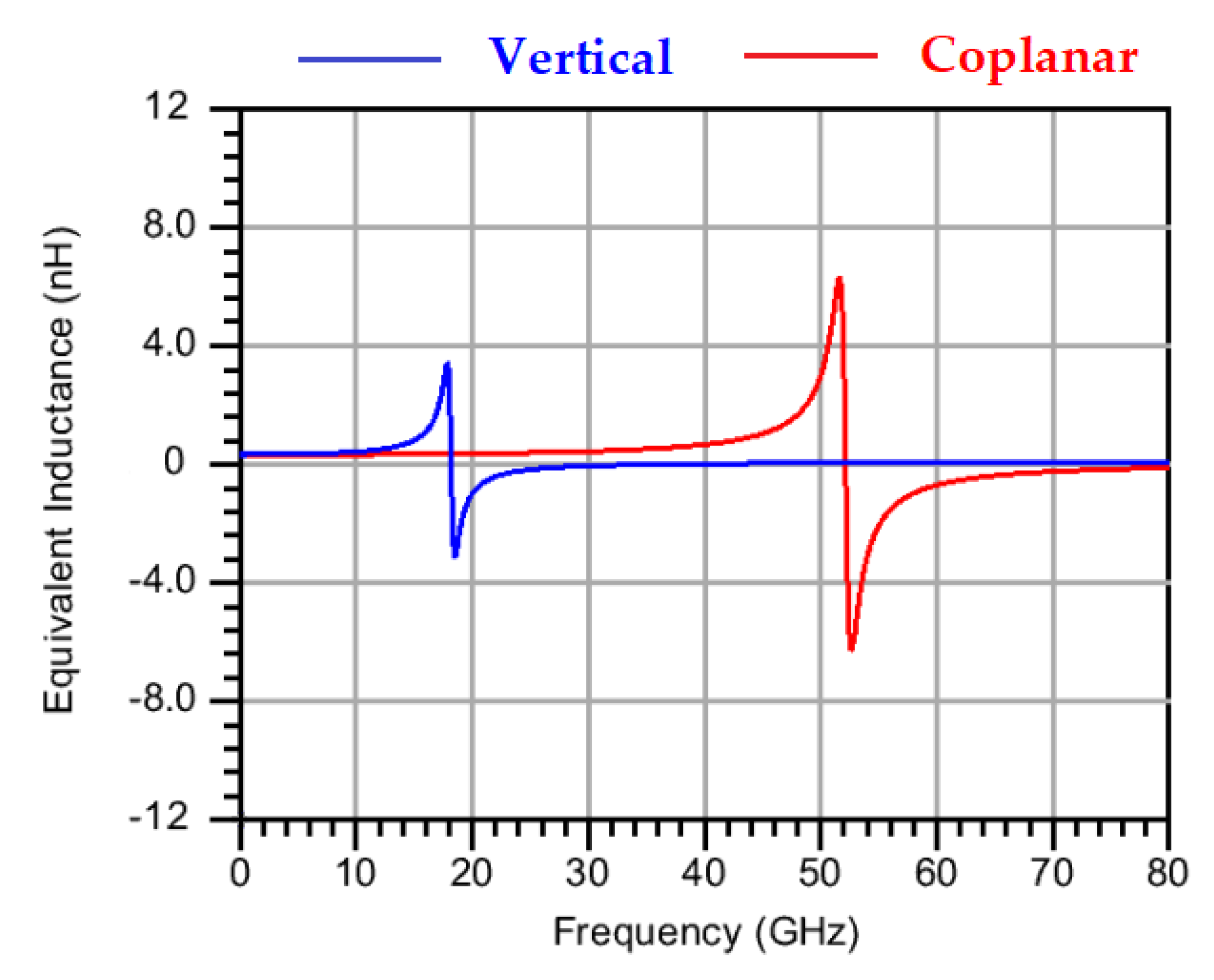
In this experiment, both the vertical and coplane transformers had 140 µm inner diameter, 10µm trace width, and the same physical scale of secondary winding. Figure 2 shows the secondary winding equivalent inductance of the two transformers. Obviously, the curves trend shows that the two inductors almost had the same inductance value at low frequency band. As the frequency went high, due to the stronger coupling effect and larger parasite capacitance, the vertical transformer’s inductor quickly met its fsrf. While the coplane transformer’s fsrf was much higher, the vertical transformer’s fsrf was 18.16 GHz, while the coplanar transformer’s fsrf was 51.98 GHz. Additionally, at 10 GHz frequency point, the coupling coefficient was 0.829 for vertical transformer and 0.521 for coplanar transformer. In Figure 2, the blue line shows a sharp inductance value variation trend near the fsrf at a low frequency band that would cause the designed transformer matching network to hardly have stable port impedance within the wide frequency band, which is unacceptable in this work. Generally, the transformer’s fsrf should be at least three times higher than the signal frequency high band. The vertical transformer’s low fsrf makes it an unideal choice.

2.2.2. Coplanar Transformer’s Inductance vs. Trace Width

Figure 3 provides transformer parameter correlated influence among w, L, fsrf. The experiment results are obtained from d = 70 µm, MET2 on-chip octagonal inductor EM simulation. As the Figure shows, the equivalent inductance and fsrf constantly reduce as the winding metal trace goes wider. As trace width increases from 6 to 18 µm, the inductance reduces from 0.315 nH to 0.266 nH, while the fsrf also reduces from 82.05 to 72.83 GHz. This illustrates that winding trace width is correlated with winding equivalent inductance, which means that by changing trace width at primary/secondary winding, we can broaden the transformer matching range.

2.2.3. w vs. s vs. k for Coplanar Transformer

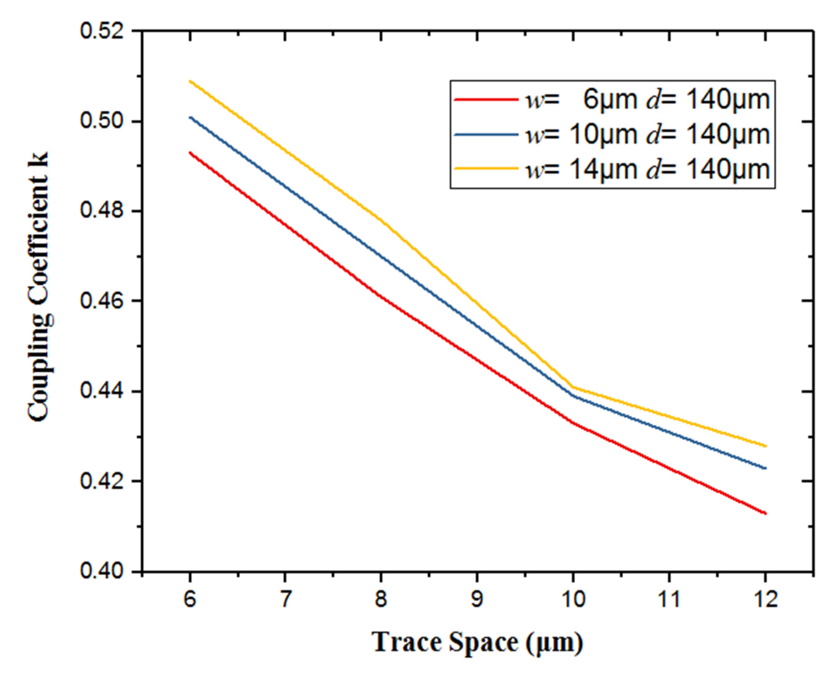
The coupling factor is mainly decided by transformer trace space s, between the primary and secondary winding. The top metal, MET2 with 4 µm thickness, is used to design octagonal coplanar transformer. In 0.25 µm GaN process DRC rules, the MET2 minimum layer space is 6 µm, which constrains the designed transformer available coupling coefficient. As Figure 4 shows, with wider trace space s and metal line width, trace width w, the transformer coupling coefficient k dramatically decreased. Another trend is that, at a constant trace space s, the coupling coefficient slightly increases with trace width. In the majority of cases, the space s is set as narrow as possible for larger transformer coupling coefficient.
Based on the experiment results above, we may safely come to the conclusion that designing a transformer on GaN process is entirely possible. Both vertical and coplanar transformers are possible to be designed on GaN process, but vertical transformers have unacceptable lower fsrf, vertical transformer bottom winding is too close to the subtract in MMIC process and will incur much more loss. A vertical transformer using a thin bottom metal layer will lower fsrf. Thus, coplanar transformer design on top thick metal is a more ideal choice for transformer designing on GaN.

3. Transformer Design and Modeling

Previous research has little concern about asymmetry coplanar transformer distributed modeling, as well as transformer design method on GaN MMIC. In practice, coplanar transformer trace widths at the primary and secondary sides are unequal, and coplanar transformer secondary inductor’s diameter is larger than the primary one. This complex asymmetry coupling structure cannot be analyzed through classical even–odd theory. Thus, a new model is proposed to solve this problem.

3.1. Asymmetry Coupling Transmission Line Theory

In this work, a coplanar asymmetry transformer with a central-tap distributed model is shown in Figure 1c, and we use an asymmetry coupling transmission line to model coupling effect between transformer primary and secondary winding (CLA and CLB in Figure 1c). The parallel asymmetric coupled line is modeled by normal mode (c and π mode) parameters [23]. For accuracy, mutual capacitance and parasite inductance are also added. According to previous research [24], the mutual capacities between the central tape and portended are crucial, so capacitance C1 and C2 are added in the model.
The method to grasp all the parameters needed to define c-π mode asymmetry coupling transmission line is listed as follows [23]:
  • Obtain the S matrix of the asymmetry coupling transmission line under specific length and the frequency through EM simulation. For this transmission line coupling, the pair has four ports and the corresponding S-parameter matrix’s dimension must be 4 × 4.
  • Then, transform the grasped S matrix into an ABCD matrix. Then all the parameters can be calculated through the following equations (note that A,B,C,D are 2 × 2 matrices and their elements are inherited from the transformer matrix in step 1).
    A = M V cos h ( γ c l ) 0 0 cosh ( γ π l ) M V 1
    B = 1 Y C 1 1 Y π 1 1 Y C 2 1 Y π 2 * M I × sin h ( γ c l ) 0 0 sinh ( γ π l ) M I 1
    C = Y C 1 Y π 1 Y C 2 Y π 2 M V × sin h ( γ c l ) 0 0 sinh ( γ π l ) M V 1
    D = M I cosh ( γ c l ) 0 0 cosh ( γ π l ) M I 1
    M V = M I T 1 = 1 1 R c R π
  • The eigenvalue decomposition on matrices A and D is applied to find the values of γ c = α c + j * β c . γ π = α π + j * β π , R c and R π , Z c 1 , Z c 2 , Z π 1 and Z π 2 can be found either by comparing the elements or by matrix operations on matrices B and C.

3.2. Asymmetric Coupling Transmission Line Simulation Model

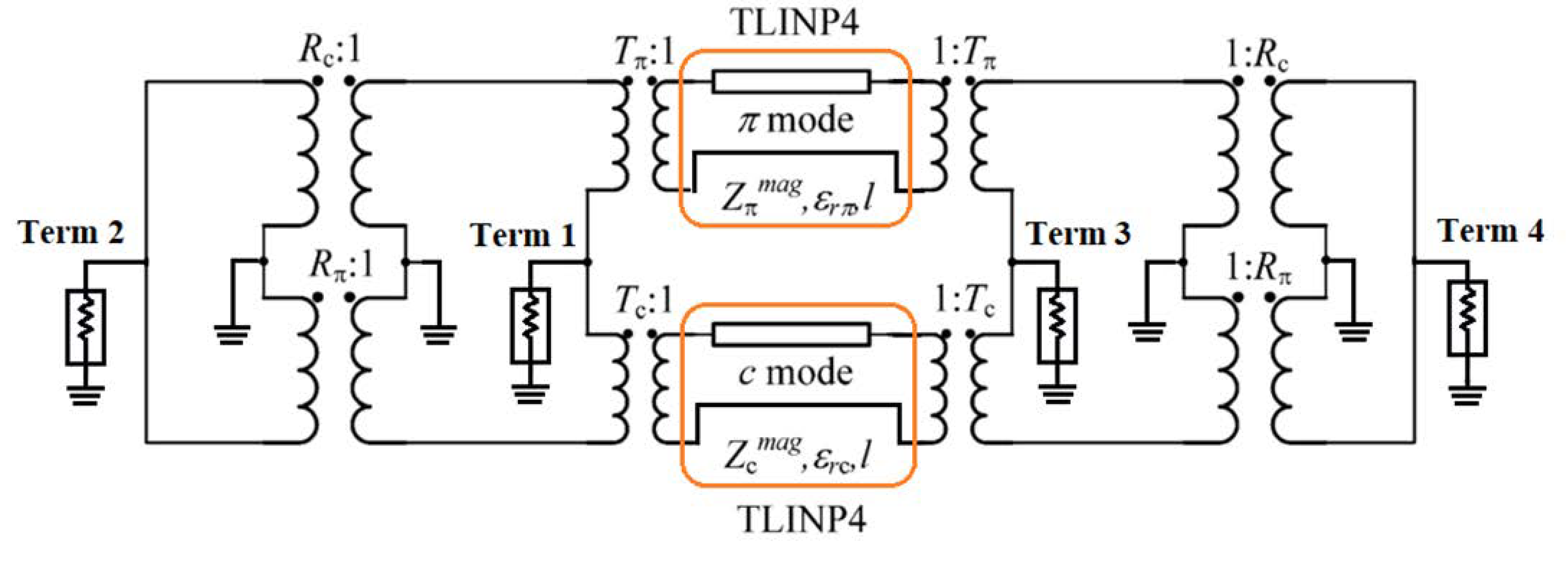
The normal mode theory calculated every parameter needed for feature coupling line, but that result was incompatible with the EDA simulation platform. In the literature [23], the asymmetry coupling line model is proposed. That model consists of a four port transmission line element and several sets of transformers, which can be applied to both frequency domain and time domain simulation. Two sets of transformers, with the turn ration Rc/π and Tc/π are inserted into the model, are able to convert complex impedance between ports. The transmission line simulation model is shown as follows:
In Figure 5, TLINP4 is a four port transmission line simulation element packaged on the EDA platform. Zπ/c represents characteristic impedance, and Zπ/cmag represents characteristic impedance’s mode. Tπ/c represents phase information when signal transmits in the model. The transformer with turning ratio Tπ/c provides a way to convert real impedance into a complex form. The correlated parameters can be deducted from the following equations:
Z π = 1 R π / R c Y π 1 = Z π m a g ( l π + j k π ) 2
T π = l π + j k π
ε r π = c 2 π f β π 2
γ π = α π + j β π
In Equations (6) and (7), Zπmag, lπ, kπ are real numbers. In Equation (8), ε r π represents relative dielectric constant in π mode, c represents speed of light, β π represents wave number in π mode. In Equation (9), γ π is propagation constant. Similarly, the parameters needed to built mode-C can also be calculated through the this process.
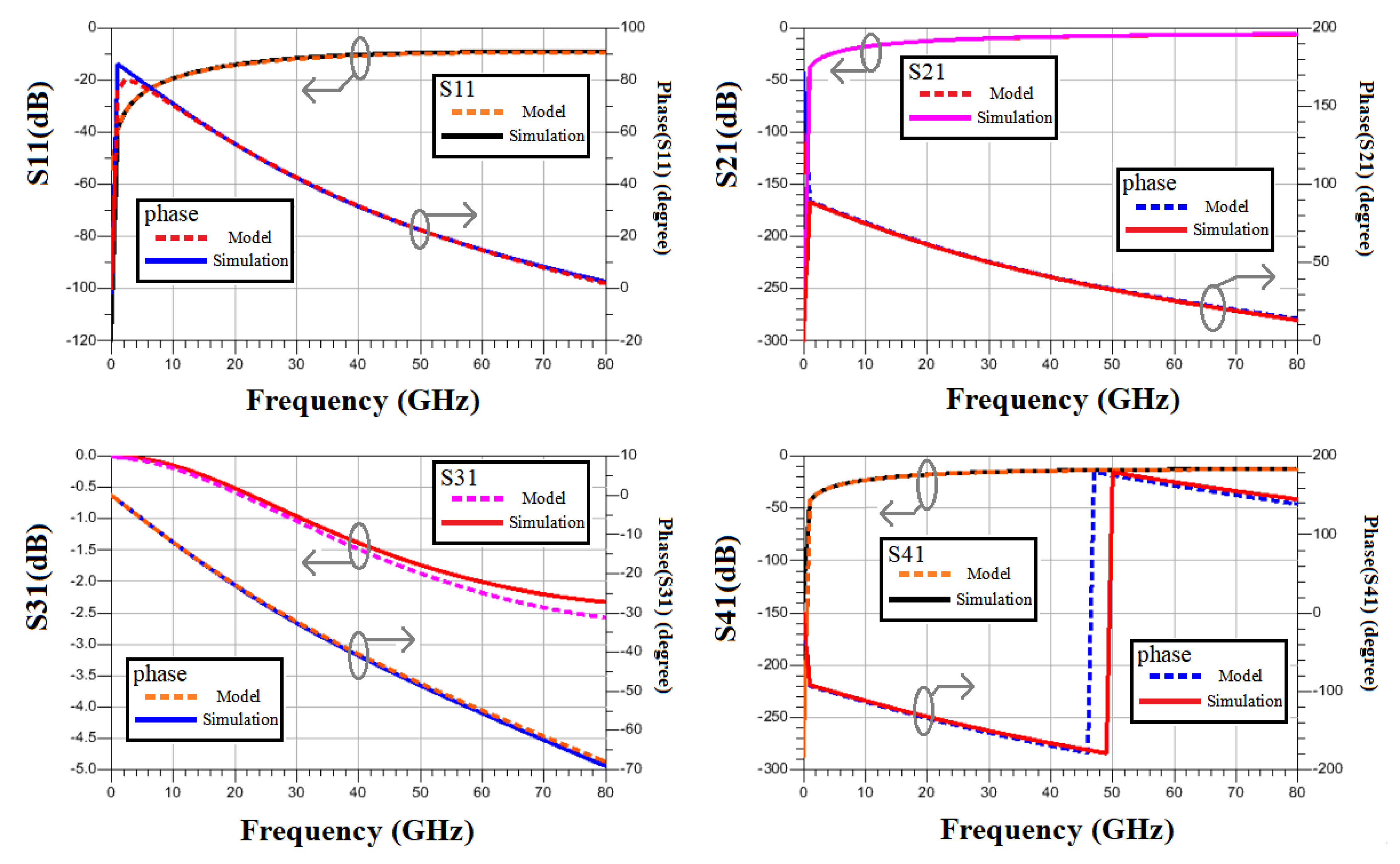
The model is set up on 0.25 µm GaN technology process. We set a parallel asymmetry coupling line on the MET2 layer, with 10 µm and 14 µm wideness respectively, 326 µm length, and 6µm trace space. Transmission line parameters were obtained from f = 10 GHz EM simulation. The calculated model parameters are listed in Table 2. Testing simulation results are shown in Figure 6. Obviously, the model performance fits simulation results with high accuracy.

3.3. Transformer Modeling Process

The distributed model modeling a transformer as a transmission line [18]. The proposed coplanar on-chip transformer distributed model is shown in Figure 1c. The central tap, port 3/6 are included in this model. The mutual coupling capacitance C1, C2, are important in single turn transformer [25], and inductance L1, L2 are added for modeling asymmetry coupling effect between primary and secondary inductance. The transformer’s Y-parameter matrix is listed in (10).
Each element in the matrix Y* is based on asymmetry coupling transmission line theory, Yij is the element we get from the transmission line model. The matrix Y* is symmetric matrix. The central tap provides DC biasing path because it behaves as an AC ground in differential mode [26], and based on experience, the central tap has little impact on the entire transformer performance. Thus, the central-tap-related Y-parameters, Yij, are omitted in this calculation. The proposed transformer model equivalent Y matrix is represented as follows:
Y * = Y 11 * Y 12 * Y 16 * Y 21 * Y 22 * Y 61 * Y 62 * Y 66 *
This major conductance element Yij* in matrix Y* is listed as follows.
Y 11 * = Y 22 * = 1 j ω · L 1 + [ j ω · L 2 | | ( j ω · C 1 ) 1 | | Y 11 1 ]
Y 44 * = Y 55 * Y 44 + j ω · C 2 + Y 14
Y 52 * = Y 41 * Y 41 · [ ( j ω · C 1 ) 1 | | j ω · L 2 | | ( Y 11 ) 1 ] j ω · L 1 + [ ( j ω · C 1 ) 1 | | j ω · L 2 | | ( Y 11 ) 1 ]
Y 25 * = Y 14 * = Y 14 · { 1 1 + j ω · L 1 [ j ω · C 1 | | Y 11 | | ( j ω · L 2 ) 1 ] }
Y 15 * = Y 51 * = Y 24 * = Y 42 * = 0
Y 66 * = 2 Y 22 1 | | [ ( j ω · C 1 ) 1 + ( Y 11 ) 1 | | j ω · ( L 1 | | L 2 ) ]
Y 33 * = 2 ( j ω · C 2 ) 1 | | { [ j ω · L 2 | | ( Y 13 ) 1 ] + [ ( j ω · C 1 ) 1 | | ( j ω · L 1 ) ] }

3.4. Comparison between the Proposed Model and Transformer Electromagnetic Simulation Results

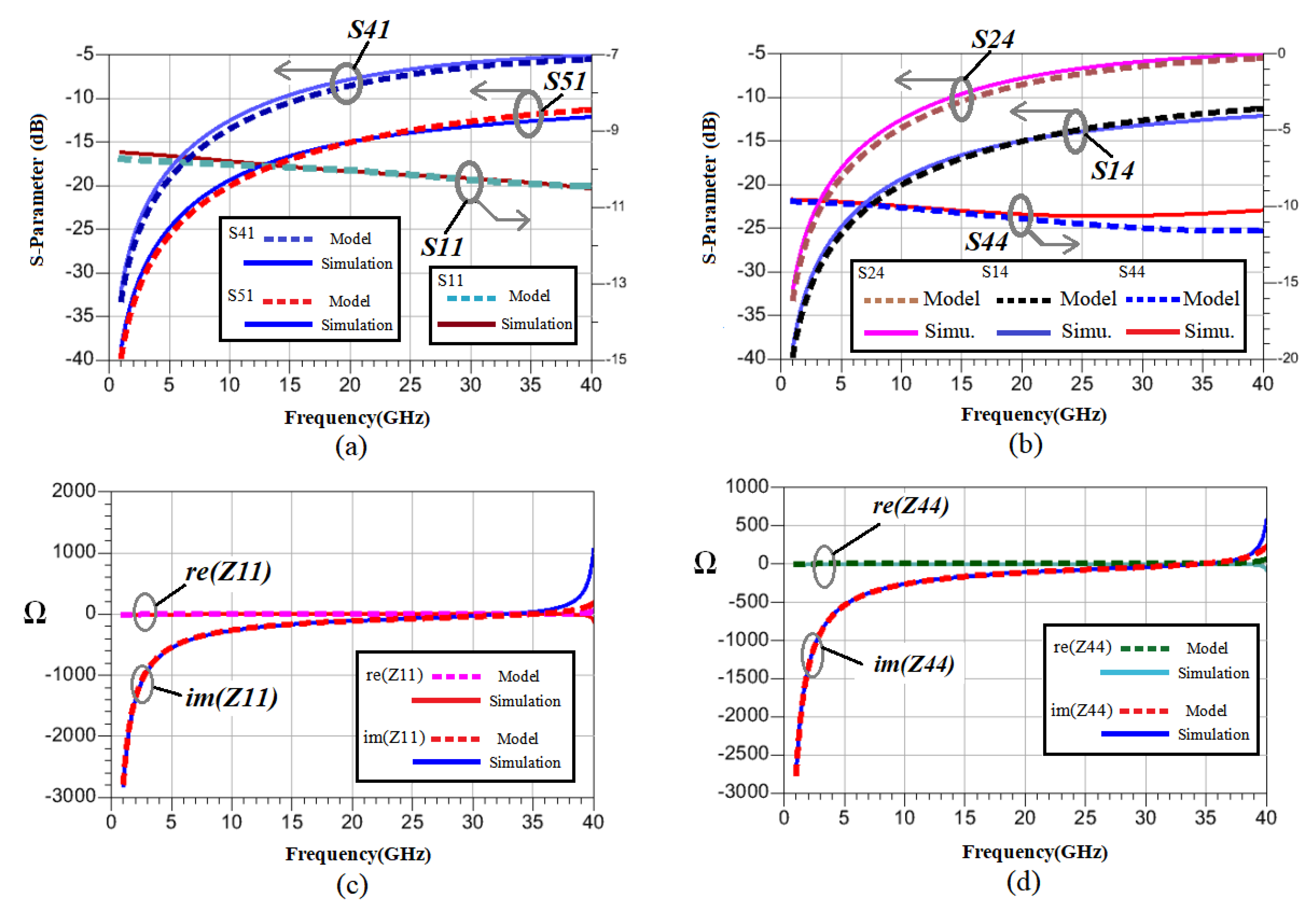
The comparison of the S-parameters from the EM simulation and the equivalent model is shown in Figure 7a. In this case, a single-turn, coplanar asymmetry transformer is modeled with 206 µm inner diameter, 10 µm trace width at primary winding, 14 µm for the secondary side, and 6 µm trace space. The transformer is designed on MET2 layer for better performance. InFigure 7, S parameters and corresponding impedance at major ports are drown.
A slight modeling error appears at the secondary winding port, S44, in Figure 7b, which may be caused by oversimplified asymmetry coupling effect at the secondary winding. Above all, a six ports device coplanar asymmetry transformer is modeled properly. Up to a millimeter wave band, the model properly fits the transformer’s feature, and all the modeled curves present the same tendency with simulation results.

4. Transformer Based Matching Mechanism

4.1. Proposed Distributed Transformer Output Network Design

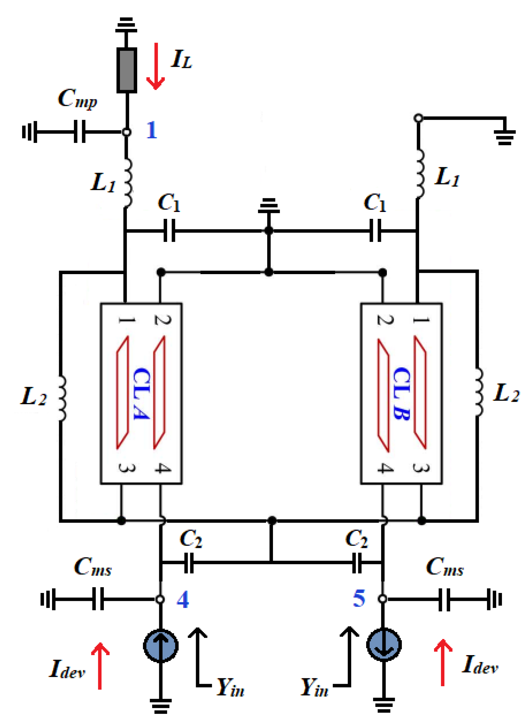
With the proposed distributed transformer model in Section 3, a differential to the single-ended transformer is used at the PA output matching part. As Figure 8 shows, differential input signal at port 4/5 is converted into a single-ended load at port 1, and power combine is achieved. The transformer also converts the device’s optimum impedance at port 4/5 into the 50 ohm at port 1. Elements Cmp and Cms represent the capacitance in the matching network which helps to adjust matching impedance.
Y 41 * · V 1 + ( Y 44 * + j ω · C m s ) V 4 + Y 45 * · V 5 = I 4
Y 51 * · V 1 + Y 54 * · V 4 + ( Y 55 * + j ω · C m s ) · V 5 = I 5
Y 11 * + j ω · C m p · V 1 + Y 14 * · V 4 + Y 15 * · V 5 = I 1
The transformer can be represented via its Y parameter, Yij* is the element deducted from the transformer model. The following equations can be deducted via the transformer Y parameter matrix.
Port 1 is connected to the load and port 4/5 are differential input ports. There exists relations: I4 = −I5 = Idev, V4= −V5 = Vdev, and IL= −YL × VL. The deducted transformer current and voltage relationship across the ports can be represented via Y−parameter matrix.
I dev I L = Y 44 * Y 45 * + j ω · C m s Y 41 * Y 14 * Y 15 * Y 11 * + j ω · C m p · V d e v V L
The input impedance Zin can be deduced from port 4/5, and Zin is targeted to match device optimum load impedance.
Z in = 1 Y in = V dev I d e v = Y L + Y 11 * + C m p Y 41 * ( Y 15 * Y 14 * ) + ( Y 44 * Y 45 * + j ω · C m s ) ( Y L + Y 11 * + j ω · C m p )

4.2. Proposed Distributed Transformer Model for Input Network Design

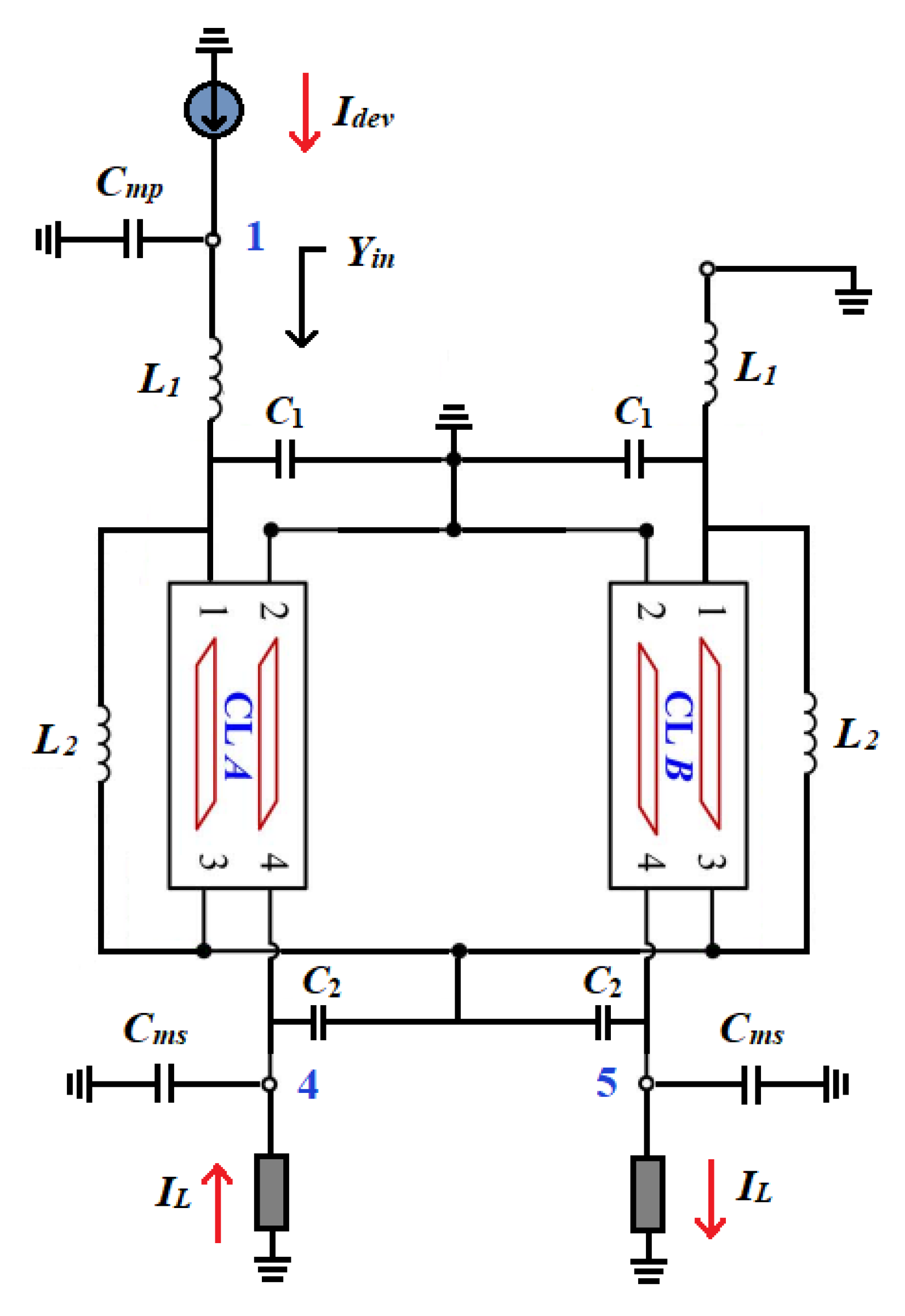
The proposed distributed transformer model for input matching network analysis is shown in Figure 9. Transformer power distribution and wideband matching is mainly used for input matching circuit. Unlike power distributors, this transformer outputs a differential signal at Port 4/5. Capacitance Cmp and Cms are loaded for matching impedance accuracy.
As Figure 9 shows, the single ended port 1 is designed to match the optimum input impedance, and port 4/5 to match optimum device impedance. Capacitance Cms sums up device impedance equivalent capacitance and the matching network capacitance. Ports 4/5 connect to the load, for they output differential signal, there exists relation, V4 = −V5 = VL, I4 = −I5 = IL and IL = −YL × VL. Then the transformer based matching circuit cross ports voltage/current relationship and input impedance are calculated in Equations (23) and (24), respectively.
I dev I L = Y 11 * + j ω · C m p Y 14 * Y 15 * Y 41 * Y 44 * Y 45 * + j ω · C m s · V d e v V L
Z in = V dev I d e v = Y 45 Y 44 j ω · C d e v Y L ( Y 11 * + j ω · C m s ) · ( Y 45 * Y 44 * j ω · C m s Y L ) + ( Y 14 * Y 15 * ) Y 41 *

4.3. Proposed Distributed Transformer Model for Interstage Network Design

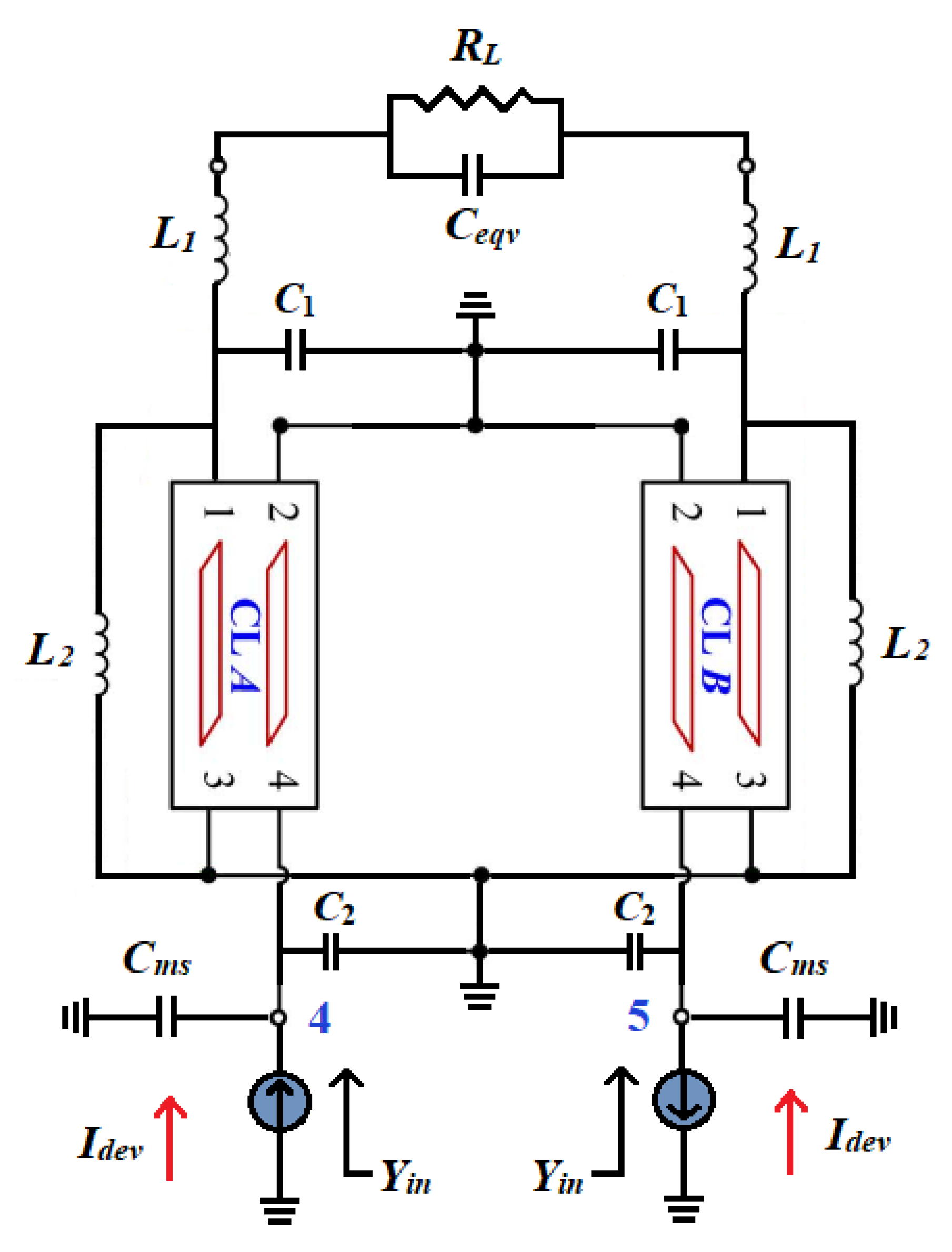
The proposed distributed transformer model for interstage matching network analysis is shown in Figure 10. RL and Ceqv parallel units represent the optimum impedance of load device. In this case, the proposed model is extended to a fully differential network for analyzing interstage matching networks. With the differential signal from the previous stage, it can be expressed as V4 = −V5 = Vdev, I4 = −I5 = Idev. Current relationship at the load is IL = −2YL × VL. Based on similar analysis methods, the resulting current and voltage relationship can be deducted as:
I dev I L = Y 44 * Y 45 * + j ω · C m p Y 41 * Y 14 * Y 15 * Y 11 * + j ω · C m s · V d e v V L
Optimum input impedance should match the device port.
Z in = V dev I d e v = 2 Y L + Y L * + j ω · C m p Y 41 * ( Y 15 * Y 14 * ) + ( Y 44 * Y 45 * + j ω · C m s ) ( 2 Y L + Y 11 * + j ω · C m p )

4.4. Transformer Design Procedure

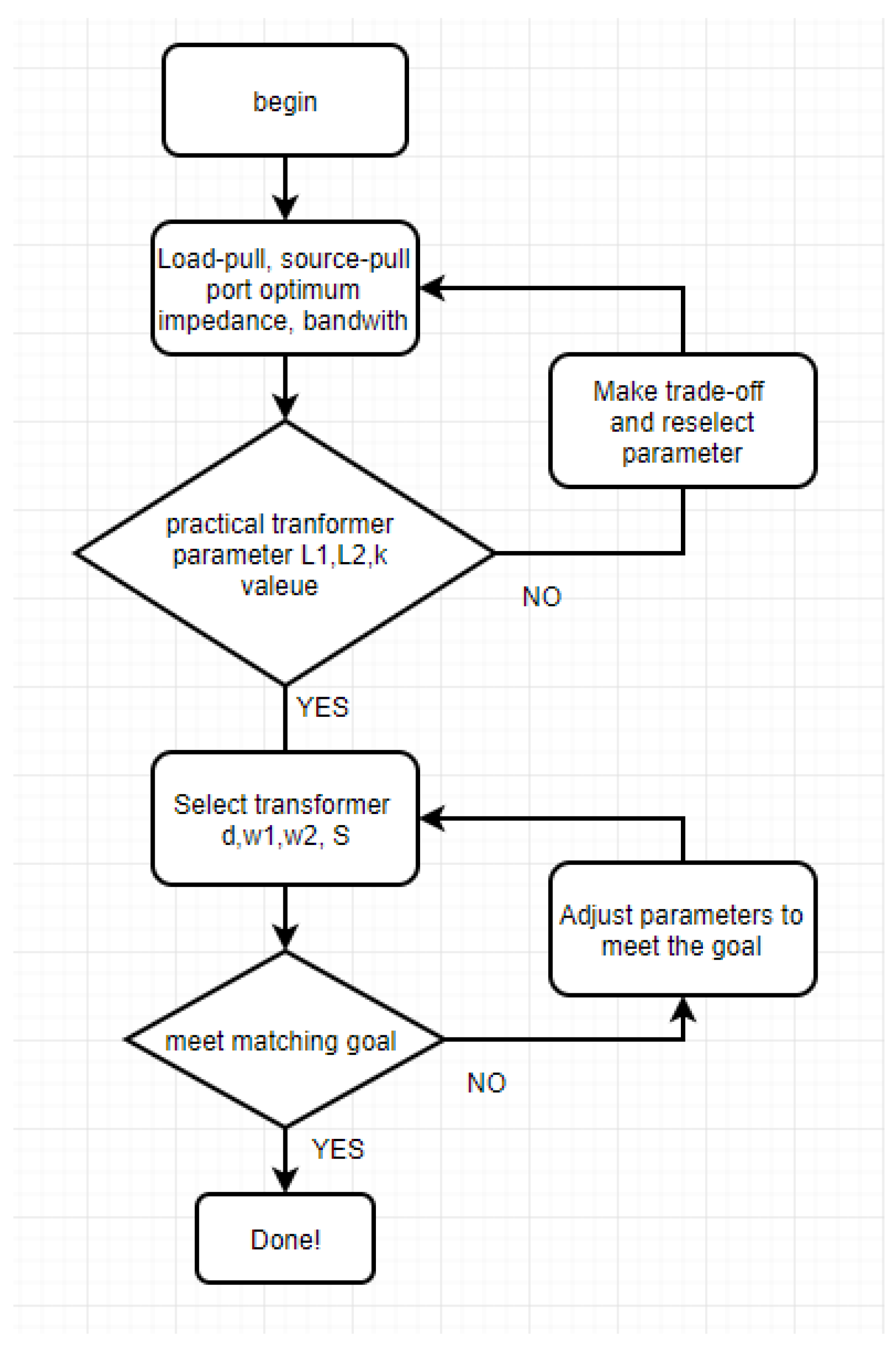
Based on the analysis above, this work provides a practical way to design coplanar asymmetry transformers, and the corresponding procedures are shown in Figure 11. To begin with, the port impedance at transformer matching circuit can be measured. Note that for maximum output power and efficiency, the output active devices in PAs must be loaded by optimum load impedance determined by the large-signal loadpull/loadline simulations, which are typically very different from conjugately matching. This is one of the major differences between small-signal linear amplifier design and PA design [27].
The target impedance acquired through load-pull and source-pull largely decides turning transformer ratio n, in Equation (27) [14]. If the n is set as for the impedance transformation, the maximum current gain can be obtained over infinite bandwidth [21].
L1 and L2 represent equivalent inductance of primary and secondary winding respectively. Coupling coefficient is related to bandwidth and gain flatness within the band of interest. In Equation (28), maximum and minimum angular frequency are represented respectively. Based on these equations, transformer schematic parameters can be determined.
n 2 = L 1 L 2 = r e ( Z opt , 1 ) r e ( Z opt , 2 )
ω L , H = ω 0 1 ± k
However, these parameters have design limitations within specific processes. At the second step, we need to judge whether the calculated parameters are of practical use in the design. For example, in 0.25 µm-GaN technology process, the inductance value should be limited to below 0.8 nH, and coupling coefficient is better to adjust under 0.5, or some other performances will suffer. Thus, we need to tune parameters and make trade-offs until a set of acceptable parameters are obtained.
The last two steps are layout design process, d represents transformer inner diameter, w1 for primary winding line width and w2 for the secondary. Parameter s represents distance between primary and secondary inductance. The simulation result can be checked via EM simulation. If the designed transformer does not meet the goal, we need to adjust the physical scale of the layout until the final design is formed.

5. Transformer Matching Based Power Amplifier Design on GaN

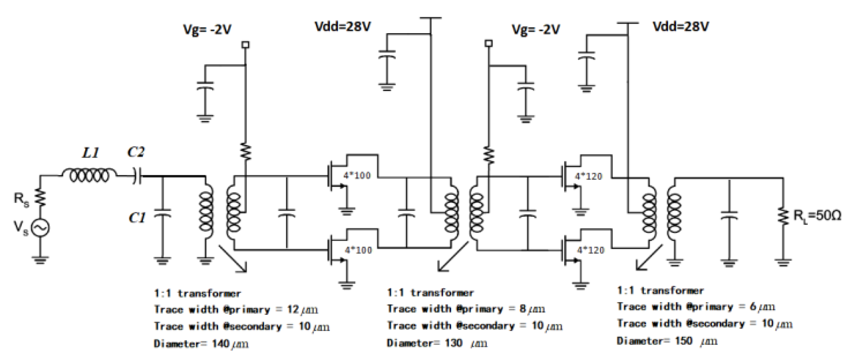
Using coplanar asymmetry on-chip transformer distributed model in this design has greatly reduced transformer layout iteration design times, and that greatly releases the designer’s pressure. The proposed two-stage drive amplifier based on a transformer matching circuit schematic and layout design are shown in Figure 12 and Figure 13.
The proposed GaN PA with transformer matching circuit is designed on a 0.25 µm GaN technology process. All three matching circuits are based on transformer design. Both the input and output ports are matched to 50 Ohm. The second stage transistors are respective choosing 4 × 120 µm OSV for larger output power, and the first stage transistor, 4 × 100 µm OSV, is chosen for sufficient power gain. They are all based at Vg = −2 V, Vd = 28 V, Class-AB condition, with the source connected to the ground and drain port biased from the transformer central tap. The transformer central tap greatly simplifies the bias circuit design process, and it is insensitive to the entire circuit performance. That enables us to design bias circuits with more freedom and explore a new method for X-band MMIC PA design.
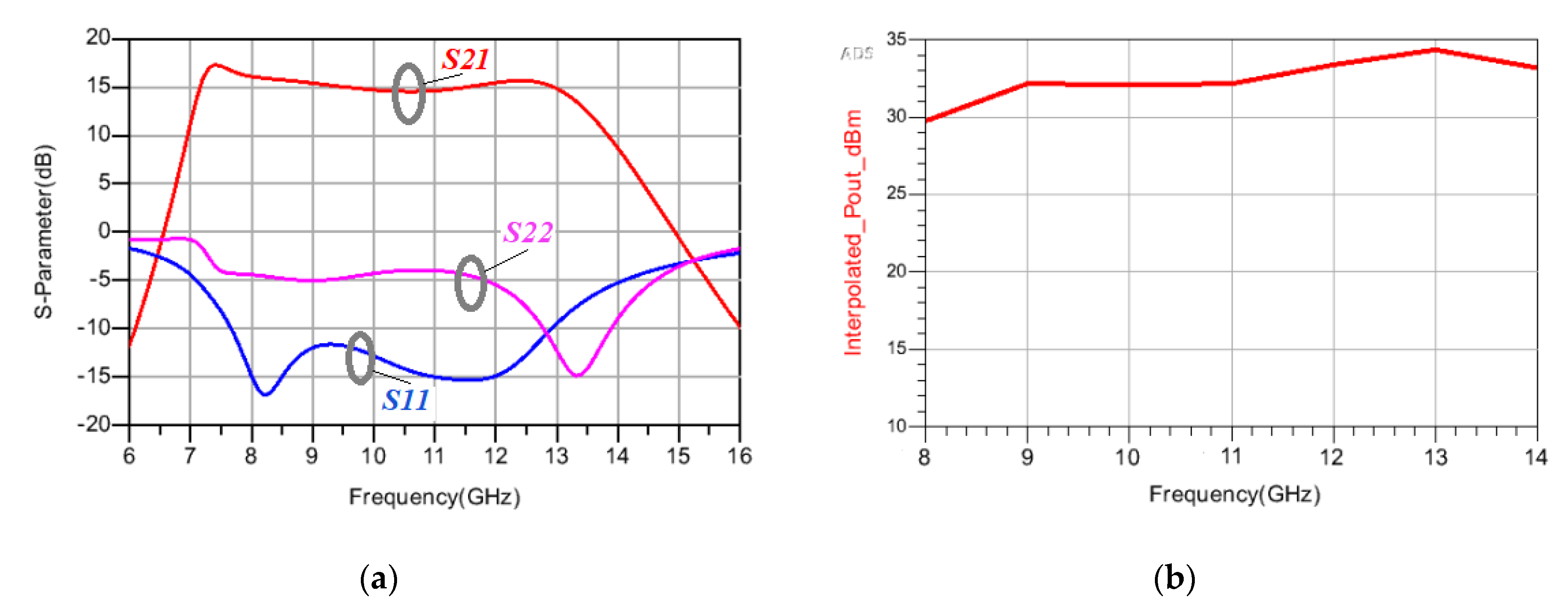
For accuracy, the PAD and bonding wires’ EM effect are included in this design. As Figure 14a shows, from 8 to 13 GHz the small-signal gain varies between 14.555~16.094 dB, and the gain flatness is 1.539 dB. The input matching is better than −11 dB within X band. Correspondingly, −4.145 [email protected] GHz for the S22. The PA output power is above 29.5 dBm within the frequency band, as shown in Figure 14b.
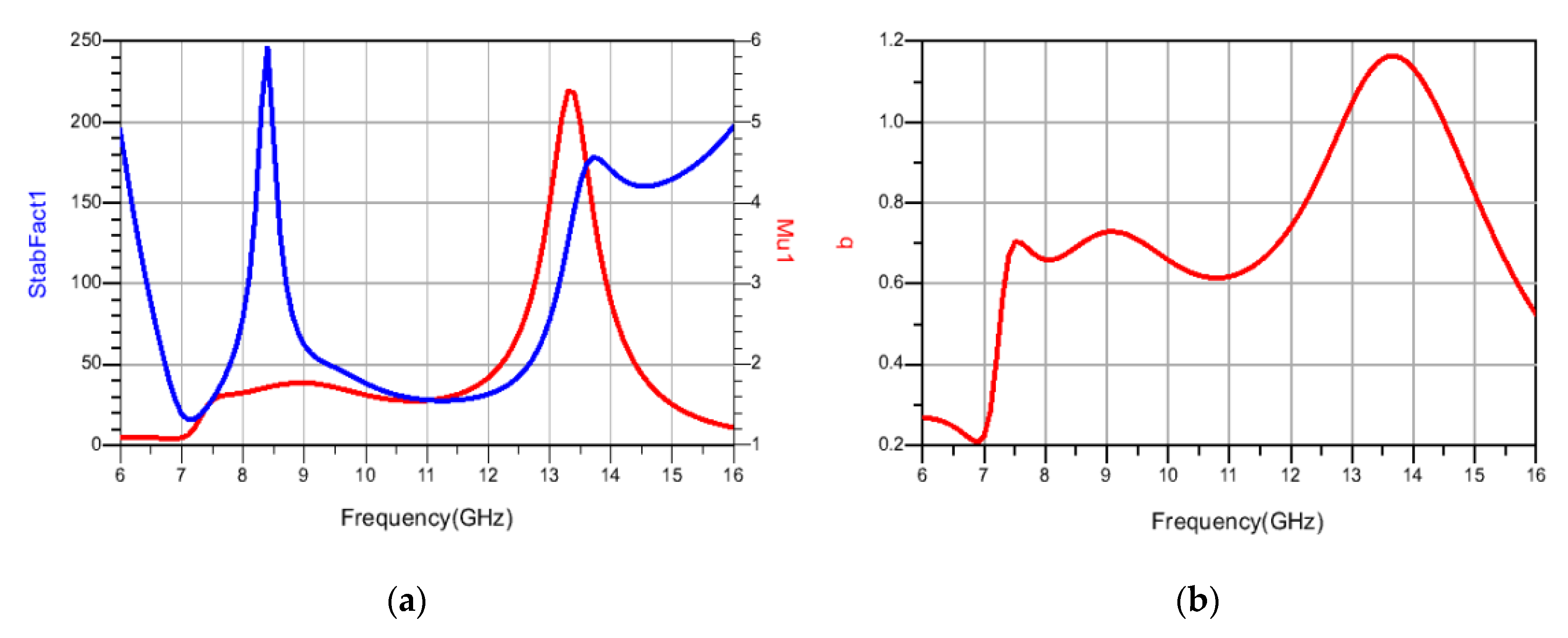
For PA stability consideration, StabFact, Mu, and b are all included and shown in Figure 15a,b. The results shows that for StabFact and Mu > 1, b > 0 in an extended frequency band, the proposed PA is unconditionally stable (the equations for factors StabFact, Mu and b are listed in Appendix A).
Table 3 presents a comprehensive performance comparison of related researches, [28,29,30,31,32] to this work designed transformer matching MMIC PA and a comparison of the latest works of other published PA over the X-band. Obviously, transformer matching topology enables a more compact layout of the circuit.

6. Conclusions

This paper proposed a coplanar asymmetry transformer distributed model for PA design on GaN technology process, and related transformer-based matching circuit designing and analyzing methods are studied. The proposed model can predict the coplanar asymmetry transformers performance up to a millimeter wave band. By using the proposed model, an X-band GaN PA with a transformer matching circuit is designed. According to previous research, this is the first case for transformer-based matching circuit design on GaN MMIC.

Author Contributions

Conceptualization, Y.F., J.W. and H.S.; methodology, Y.F., Z.Y., S.Z., N.X., J.Z., Z.Y. and H.S.; Resources, J.W., Z.Y., S.Z., J.Z., G.G., X.Z., N.X. and Y.Z.; software, N.X., J.W. and H.S.; validation, Y.F., J.W., G.G., J.Z., X.Z. and Z.Y.; data curation, Y.F. and G.G.; writing—original draft preparation, Y.F., J.W. and Z.Y.; writing—review and editing, J.W., X.L. and Y.Y.; project administration, J.W., X.L. and Y.Y. All authors have read and agreed to the published version of the manuscript.

Funding

This research received no external funding.

Conflicts of Interest

The authors declare no conflict of interest.

Appendix A

The stable factors in this design including StabFact, Mu and b, corresponding equations are listed below:
S t a b F a c t = { 1 | S 11 | 2 | S 22 | 2 + | S 11 · S 22 S 12 · S 21 | 2 } / { 2 · | S 12 · S 21 | }
M u = { 1 S 22 2 } / { | S 11 c o n j ( S 22 ) · | + | S 21 · S 12 | } delta = S 11 · S 22 S 12 · S 21
b = 1 + | S 11 | 2 | S 22 | 2 | S 11 · S 22 S 12 · S 21 | 2

References

  1. Ma, Z.; Ma, K.; Wang, K.; Meng, F. A 28 GHz Compact 3-Way Transformer-Based Parallel-Series Doherty Power Amplifier With 20.4%/14.2% PAE at 6-/12-dB Power Back-off and 25.5 dBm PSAT in 55 nm Bulk CMOS. In Proceedings of the IEEE International Conference on Solid-State Circuits (ISSCC), San Francisco, CA, USA, 20–26 February 2022. [Google Scholar]
  2. Li, Y.; Yin, Y.; Zheng, D.; Jia, X.; Lin, J.; Gao, F.; Zhu, Y.; Xiong, L.; Yan, N.; Lu, Y.; et al. A 15-Bit Quadrature Digital Power Amplifier with Transformer-Based Complex-Domain Efficiency Enhancement. IEEE J. Solid-State Circuits 2022, 57, 1610–1622. [Google Scholar] [CrossRef]
  3. Pashaeifar, M.; de Vreede, L.C.N.; Alavi, M.S. 14.4 A 24-to-30 GHz Double-Quadrature Direct-Upconversion Transmitter with Mutual-Coupling-Resilient Series-Doherty Balanced PA for 5G MIMO Arrays. In Proceedings of the IEEE International Conference on Solid-State Circuits (ISSCC), San Francisco, CA, USA, 20–26 February 2022. [Google Scholar]
  4. Zhang, J.; Cheng, Y.; Zhao, C.; Wu, Y.; Kang, K. Analysis and Design of Ultra-Wideband mm-Wave Injection-Locked Frequency Dividers Using Transformer-Based High-Order Resonators. IEEE J. Solid-State Circuits 2018, 53, 2177–2189. [Google Scholar] [CrossRef]
  5. Wang, F.; Wang, H. A Noise Circulating Oscillator. IEEE J. Solid-State Circuits 2019, 54, 696–708. [Google Scholar] [CrossRef]
  6. Long, J. Monolithic transformers for silicon RF IC design. IEEE J. Solid-State Circuits 2000, 35, 1368–1382. [Google Scholar] [CrossRef]
  7. Chiu, T.-Y.; Wang, Y.; Wang, H. A Ka-Band Transformer-Based Switchless Bidirectional PA-LNA in 90-nm CMOS Process. In Proceedings of the Microwave, MTT-S International Symposium, Atlanta, GA, USA, 6–11 June 2021. [Google Scholar]
  8. Shao, H.; Qi, G.; Mak, P.I.; Martins, R.P. A 1.7–3.6GHz 20 MHz-Bandwidth Channel-Selection N-Path Pas-sive-LNA Using a Switched-Capacitor-Transformer Network Achieving 23.5 dBm OB-IIP3 and 3.4–4.8dB NF. IEEE J. Solid-State Circuits 2022, 57, 413–422. [Google Scholar] [CrossRef]
  9. Ju, I.; Gong, Y.; Cressler, J.D. Highly Linear High-Power 802.11ac/ax WLAN SiGe HBT Power Amplifiers with a Compact 2nd-Harmonic-Shorted Four-Way Transformer and a Thermally Compensating Dynamic Bias Circuit. IEEE J. Solid-State Circuits 2020, 55, 2356–2370. [Google Scholar] [CrossRef]
  10. Chowdhury, D.; Reynaert, P.; Niknejad, A. Design considerationsfor 60 GHz transformer coupled CMOS power amplifiers. IEEE J. Solid-State Circuits 2009, 44, 2733–2744. [Google Scholar] [CrossRef]
  11. Ma, Z.; Ma, Z.; Ma, K. A 35 dBm PSAT and 41% PAE GaAs Power Amplifier with Series Distributed-Balun. IEEE Trans. Circuits Syst. II Express Briefs 2022, 1. [Google Scholar]
  12. Jia, H.; Prawoto, C.C.; Chi, B.; Wang, Z.; Yue, C.P. A Full Ka-Band Power Amplifier With 32.9% PAE and 15.3-dBm Power in 65-nm CMOS. IEEE Trans. Circuits Syst. Regul. Pap. 2018, 65, 2657–2668. [Google Scholar] [CrossRef]
  13. Niknejad, A.M.; Meyer, R.G. Analysis, design, and optimization of spiral inductors and transformers for Si RFICs. IEEE J. Solid-State Circuits 1998, 33, 1470–1481. [Google Scholar] [CrossRef] [Green Version]
  14. Wang, H.; Sideris, C.; Hajimiri, A. A CMOS Broadband Power Amplifier with a Transformer-Based High-Order Output Matching Network. IEEE J. Solid-State Circuits 2010, 45, 2709–2722. [Google Scholar] [CrossRef] [Green Version]
  15. Ye, W.; Ma, K.; Yeo, K.S. 2.5 A 2-to-6 GHz Class-AB power amplifier with 28.4% PAE in 65 nm CMOS supporting 256 QAM. In Proceedings of the IEEE International Solid-State Circuits Conference, Digest of Technical Papers, San Francisco, CA, USA, 22–26 February 2015; pp. 1–3. [Google Scholar]
  16. Zhao, J.; Bassi, M.; Bevilacqua, A.; Ghilioni, A.; Mazzanti, A.; Svelto, F. A 4067 GHz power amplifier with 13 dBm PSAT and 16% PAE in 28 nm CMOS LP. IEEE J. Solid-State Circuits 2015, 50, 1618–1628. [Google Scholar]
  17. Hou, D.; Hong, W.; Goh, W.L.; Xiong, Y.Z.; Arasu, M.A.; He, J.; Chen, J.; Madihian, M. Distributed Modeling of Six-Port Transformer for Millimeter-Wave SiGe BiCMOS Circuits Design. IEEE Trans. Microw. Theory Tech. 2012, 60, 3728–3738. [Google Scholar] [CrossRef]
  18. Cheung, T.S.D.; Long, J.R. Design and Modeling of mm-Wave Monolithic Transformers. In Proceedings of the Bipolar/BiCMOS Circuits and Technology Meeting, Maastricht, The Netherlands, 8–10 October 2006; pp. 1–4. [Google Scholar]
  19. Wang, F.; Wang, H. A Broadband Linear Ultra-Compact mm-Wave Power Amplifier With Distributed-Balun Output Network: Analysis and Design. IEEE J. Solid-State Circuits 2021, 56, 2308–2323. [Google Scholar] [CrossRef]
  20. Zhu, W.; Wang, J.; Wang, R.; Zhang, J.; Li, C.; Yin, S.; Wang, Y. A 1V 32.1 dBm 92-to-102 GHz Power Amplifier with a Scalable 128-to-1 Power Combiner Achieving 15% Peak PAE in a 65 nm Bulk CMOS Process. In Proceedings of the IEEE International Solid-State Circuits Conference (ISSCC), San Francisco, CA, USA, 20–26 February 2022. [Google Scholar]
  21. Li, C.-H.; Kuo, C.-N.; Kuo, M.-C. A 1.2-V 5.2-mW 20–30-GHz Wideband Receiver Front-End in 0.18-µm CMOS. IEEE Trans. Microw. Theory Tech. 2012, 60, 3502–3512. [Google Scholar]
  22. Ye, W.; Ma, K.; Yeo, K.S.; Zou, Q. A 65 nm CMOS Power Amplifier with Peak PAE above 18.9% From 57 to 66 GHz Using Synthesized Transformer-Based Matching Network. IEEE Trans. Circuits Syst. I Regul. Pap. 2015, 62, 2533–2543. [Google Scholar] [CrossRef]
  23. Tsai, C.-M.; Gupta, K. A generalized model for coupled lines and its applications to two-layer planar circuits. IEEE Trans. Microw. Theory Tech. 1992, 40, 2190–2199. [Google Scholar] [CrossRef]
  24. Bei, S. Design and Optimization of Monolithic Spiral Transformers and Baluns. Master’s Thesis, Southeast University, Nanjing, China, 2006. [Google Scholar]
  25. Brink Hoff, J.; Pham, D.D.; Kang, K.; Lin, F. Anew six-port transformer modeling methodology applied to 10-dBm 60-GHz CMOS ask modulator designs. IEEE Trans. Microw. Theory Tech. 2010, 58, 297–309. [Google Scholar] [CrossRef]
  26. Qunaj, V.; Reynaert, P. Compact Transformer-Based Matching Structures for Ka-Band Power Amplifiers. In Proceedings of the IEEE Asia-Pacific Microwave Conference (APMC), Singapore, 1 December 2019. [Google Scholar]
  27. Wang, H.; Sengupta, K. RF and Mm-wave Power Generation in Silicon; Academic Press: Cambridge, MA, USA, 2015. [Google Scholar]
  28. Schuh, P.; Leberer, R.; Sledzik, H.; Oppermann, M.; Adelseck, B.; Brugger, H.; Quay, R.; Mikulla, M.; Weimann, G. Advanced High Power Amplifier Chain for X-Band T/R-Modules based on GaN MMICs. In Proceedings of the European Microwave Integrated Circuits Conference, Manchester, UK, 10–13 September 2006. [Google Scholar]
  29. Schuh, P.; Sledzik, H.; Reber, R.; Fleckenstein, A.; Leberer, R.; Oppermann, M.; Quay, R.; van Raay, F.; Seelmann-Eggebert, M.; Kiefer, R.; et al. GaN MMIC based T/R-Module Front-End for X-Band Applications. In Proceedings of the European Microwave Integrated Circuits Conference, Amsterdam, The Netherlands, 27–28 October 2008. [Google Scholar]
  30. Kang, L.; Chen, W.; Wu, A. A Reconfigurable S-/X-Band GaN MMIC Power Amplifier. IEEE Microw. Wirel. Compon. Lett. 2022, 32, 547–550. [Google Scholar] [CrossRef]
  31. Kim, D.; Lee, D.-H.; Sim, S.; Jeon, L.; Hong, S. An X-Band Switchless Bidirectional GaN MMIC Amplifier for Phased Array Systems. IEEE Microw. Wirel. Compon. Lett. 2014, 24, 878–880. [Google Scholar] [CrossRef]
  32. Xie, C.; Wu, P.; Tan, C.; Yuan, Y.; Zeng, J.; Yu, Z. An X/Ku Dual-Band Switchless Frequency Reconfigurable GaAs Power Amplifier. IEEE Microw. Wirel. Compon. Lett. 2022, 32, 539–542. [Google Scholar] [CrossRef]
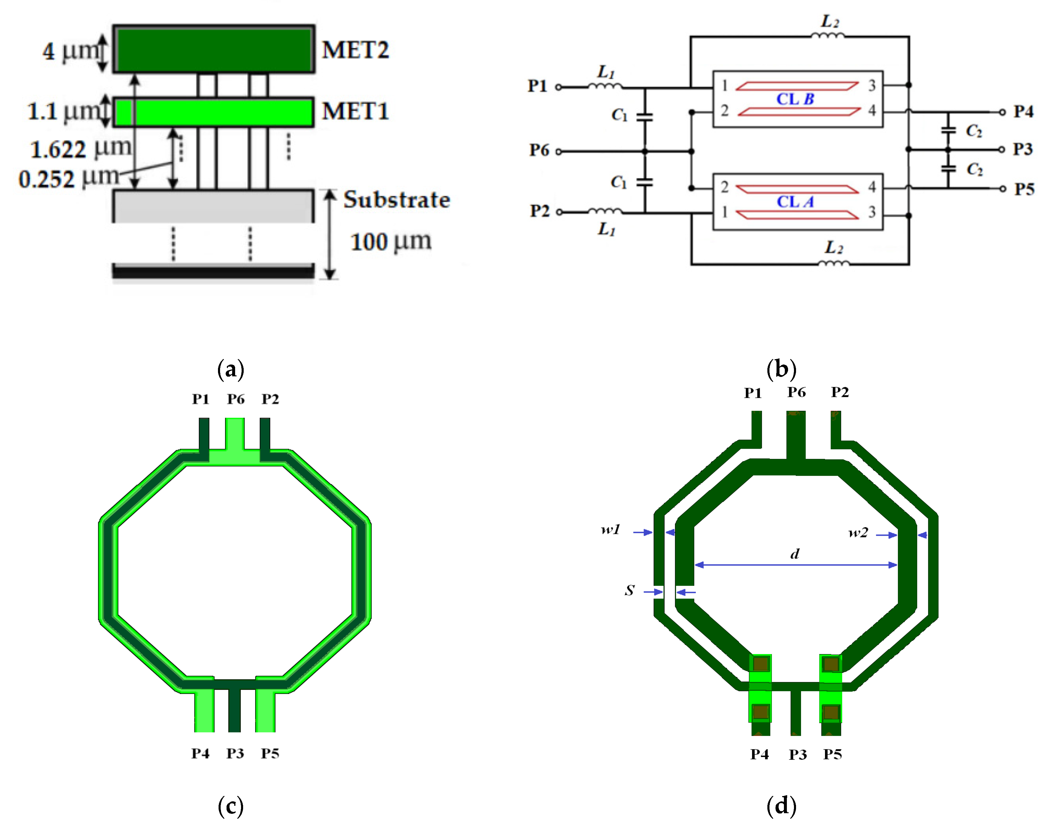
Figure 1. On-chip transformer and its equivalent model. (a) 0.25 µm-GaN process cross view section, (b) the proposed coplanar transformer distributed model, (c) vertical transformer layout design, (d) coplane transformer layout design.
Electronics 11 02478 g001
Figure 2. The secondary winding equivalent inductance comparison for vertical and coplanar transformer on the GaN process, d = 140 µm, w1,2 = 10 µm, s = 6 µm.
Electronics 11 02478 g002
Figure 3. Comparison of equivalent inductance and fsrf at primary winding of the coplanar transformer with different trace width.
Electronics 11 02478 g003
Figure 4. Comparison of coupling coefficient of coplanar transformer with different trace width.
Electronics 11 02478 g004
Figure 5. The equivalent model of asymmetry coupling transmission line [17].
Electronics 11 02478 g005
Figure 6. The comparison of asymmetry coupling line EM simulation results and equivalent model S−parameter performance.
Electronics 11 02478 g006
Figure 7. The performance comparison of asymmetry coplanar transformer EM simulation results and the proposed model. (a) S−parameter from primary side, (b) S−parameter from secondary side, (c) Equivalent input impedance, (d) Equivalent output impedance.
Electronics 11 02478 g007
Figure 8. The analysis of proposed distributed transformer model for power combine.
Electronics 11 02478 g008
Figure 9. Analysis of the proposed distributed transformer model under power distribution condition.
Electronics 11 02478 g009
Figure 10. The analysis of proposed distributed transformer model under inter-stage matching condition.
Electronics 11 02478 g010
Figure 11. Design procedure for the proposed distributed coplanar asymmetry transformer on GaN process.
Electronics 11 02478 g011
Figure 12. Transformer−coupled two−stage PA schematic.
Electronics 11 02478 g012
Figure 13. Layout of proposed transformer−coupled two stage PA.
Electronics 11 02478 g013
Figure 14. Simulation results of the proposed drive amplifier. (a) PA small−signal performance, (b) output power of the drive amplifier.
Electronics 11 02478 g014
Figure 15. Stability simulation of the PA. (a) StabFact and Mu, (b) b factor.
Electronics 11 02478 g015
Table 1. Technology process parameter comparison for transformer design.
Technology ProcessTSMC 0.13 µm RF CMOSTSMC 0.18 µm RF CMOSTSMC 0.25 µm
RF CMOS
0.15 µm
InGaAs pHEMT
0.25 µm GaN on Sic
Number of metal layers86522
Min. metal layer space
(Top thick metal)
(µm)
-1.5-4
(MET2 scale > 50 µm)
6
Top layer Metal thickness (µm)3.32.340.9924
Top metal to substrate distance (µm)7.4708.157.475.21.62
Top metal conductance (S/m)5.816 × 1072.464 × 1072.464 × 1074.1 × 1074.1 × 107
Substrate dielectric constant11.911.911.912.99.7
All the data, collected from PDK, only serves for research use.
Table 2. The calculated parameters of asymmetry coupling transmission line model.
ParameterValueParameterValue
ε r c 3.9599 Z c mag 81.0430
ε r π 5.6313 Z π mag 416.2361
R C −0.7836 + j × 0.0032 T c 0.9998 − j × 0.0215
R π 1.0194 + j × 0.0011 T π 1 − j × 0.0015
Table 3. Performance summary and comparison with related researches [28,29,30,31,32].
Ref.[28][29][30][31][32]This Work
ProcessGaNGaN0.25 µm GaN0.25 µm GaN0.25 µm GaAs0.25 µm GaN
StructureTwo-stageTwo-stageTwo-stageDistributedTwo-stageTwo-stage
Matching TopologyReactiveReactiveReactiveReactiveReactiveTransformer matching
Vdd (V)353028205/828
Bandwidth (GHz)8~128.5~1410~128~128.5~9.58~12
Gain (dB)16-12~1524~3019.615
IRL (dB)--−14<−11<−9<−11
P1dB (dBm)28~29.1----24.54~28.16
Psat (dBm)~3234.5~38.23130.5~32.528.8~29.629.64~33.05
Power consumptionsat (W)19.51-5.49~6.718.15~11.952.0310.07~14.89
PAEsat (%)8-18~2210.5~15.433.5~44.45.3~11.55
Chip Size (mm2)664.864.6741.151
Publisher’s Note: MDPI stays neutral with regard to jurisdictional claims in published maps and institutional affiliations.