Rise Time and Peak Current Measurement of ESD Current from Air Discharges with Uncertainty Calculation
Abstract
:1. Introduction
2. The IEC 61000-4-2
3. Test Setup
4. Uncertainty in Measurements
4.1. Short Introduction to Uncertainty
4.2. Calculation of Uncertainties
5. Results and Discussion
5.1. Measurement Results
5.2. Uncertainty Calculations
5.3. Results Discussion
6. Conclusions
Author Contributions
Funding
Conflicts of Interest
References
- Wang, A. Practical ESD Protection Design, 1st ed.; Wiley: Hoboken, NJ, USA; IEEE Press: Piscataway, NJ, USA, 2021. [Google Scholar]
- Bafleur, M.; Caignet, F.; Nolhier, N. ESD Protection Methodologies: From Component to System, 1st ed.; ISTE Press: London, UK; Elsevier: Amsterdam, The Netherlands, 2017. [Google Scholar]
- Yousaf, J.; Shin, J.; Lee, H.; Nah, W.; Youn, J.; Lee, D.; Hwank, C. Efficient Circuit and an EM Model of an Electrostatic Discharge Generator. IEEE Trans. Electromagn. Compat. 2018, 60, 1078–1086. [Google Scholar] [CrossRef]
- Pommerenke, D. EMC fundamentals—ESD. In Proceedings of the IEEE International Symposium on Electromagnetic Compatibility & Signal/Power Integrity (EMCSI), Gaithersburg, MD, USA, 4–12 August 2017. [Google Scholar] [CrossRef]
- Zhou, J.; Guo, Y.; Shinde, S.; Hosseinbeig, A.; Patnaik, A.; Izadi, O.H.; Zeng, C.; Shi, J.; Maeshima, J.; Shumiya, H.; et al. Measurement Techniques to Identify Soft Failure Sensitivity to ESD. IEEE Trans. Electromagn. Compat. 2020, 62, 1007–1016. [Google Scholar] [CrossRef]
- Lin, H.; He, S.-Z.; Wang, Y.-L.; Liang, X.-S.; Ji, Q.-Z. Study on Electrostatic Discharge Damage and Defect Damage Failure Analysis Technology for Semiconductor Devices. In Proceedings of the 19th International Conference on Electronic Packaging Technology (ICEPT), Shanghai, China, 8–11 August 2018. [Google Scholar] [CrossRef]
- Liu, Y.; Chen, R.; Li, B.; En, Y.F.; Chen, Y.Q. Analysis of Indium–Zinc–Oxide Thin-Film Transistors Under Electrostatic Discharge Stress. IEEE Trans. Electron Devices 2018, 65, 356–360. [Google Scholar] [CrossRef]
- Kuznetsov, V. HBM, MM, and CBM ESD Ratings Correlation Hypothesis. IEEE Trans. Electromagn. Compat. 2018, 60, 107–114. [Google Scholar] [CrossRef]
- Katsivelis, P.K.; Fotis, G.P.; Gonos, I.F.; Koussiouris, T.G.; Stathopulos, I.A. Electrostatic Discharge Current Linear Approach and Circuit Design Method. Energies 2010, 3, 1728–1740. [Google Scholar] [CrossRef] [Green Version]
- Vita, V.; Fotis, G.P.; Ekonomou, L. An Optimization Algorithm for the Calculation of the Electrostatic Discharge Current Equations’ Parameters. WSEAS Trans. Circuits Syst. 2016, 15, 224–228. [Google Scholar]
- Vita, V.; Fotis, G.P.; Ekonomou, L. Parameters’ optimisation methods for the electrostatic discharge current equation. Int. J. Energy 2017, 11, 1–6. [Google Scholar]
- Wilson, P.F.; Ma, M.T. Field radiated by electrostatic discharges. IEEE Trans. Electromagn. Compat. 1991, 33, 10–18. [Google Scholar] [CrossRef]
- Kim, K.C.; Lee, K.S.; Lee, D.I. Estimation of ESD current waveshapes by radiated electromagnetic fields. IEICE Trans. Commun. 2000, E83-B, 608–612. [Google Scholar]
- Ishigami, S.; Gokita, R.; Nishiyama, Y.; Yokoshima, I. Measurements of fast transient fields in the vicinity of short gap discharges. IEICE Trans. Commun. 1995, E78-B, 199–206. [Google Scholar]
- Frei, S.; Pommerenke, D. A transient field measurement system to analyze the severity and occurrence rate of electrostatic discharge (ESD). J. Electrost. 1998, 44, 191–203. [Google Scholar] [CrossRef]
- Leuchtmann, P.; Sroka, J. Transient field simulation of electrostatic discharge (ESD) in the calibration setup (ace. IEC 61000-4-2). In Proceedings of the International Symposium on EMC, Washington, DC, USA, 21–25 August 2000. [Google Scholar]
- Leuchtmann, P.; Sroka, J. Enhanced field simulations and measurements of the ESD calibration setup. In Proceedings of the International Symposium on EMC, Montreal, QC, Canada, 13–17 August 2001. [Google Scholar]
- Becanovic, N.; Mousavi, S.M.; Fellner, G.; Pommerenke, D. A Portable Test Platform for Capturing ESD Induced Fields. In Proceedings of the IEEE International Joint EMC/SI/PI and EMC Europe Symposium, Raleigh, NC, USA, 26 July–13 August 2021. [Google Scholar] [CrossRef]
- Li, D.Z.; Zhou, J.; Hosseinbeig, A.; Pommerenke, D. Transient electromagnetic co-simulation of electrostatic air discharge. In Proceedings of the 39th Electrical Overstress/Electrostatic Discharge Symposium (EOS/ESD), Tucson, AZ, USA, 10–14 September 2017. [Google Scholar] [CrossRef]
- Ishigami, S.; Kawamata, K.; Minegishi, S.; Fujiwara, O. Measurement of electric field waveform caused by micro gap ESD in a pair of spherical electrodes. In Proceedings of the Asia-Pacific International Symposium on Electromagnetic Compatibility (APEMC), Seoul, Korea, 20–23 June 2017. [Google Scholar] [CrossRef]
- Kawamata, K.; Ishigami, S.; Minegishi, S.; Fujiwara, O. Distance characteristic of electric field waveform and field peak value caused by micro gap ESD in a pair of spherical electrodes. In Proceedings of the International Symposium on Electromagnetic Compatibility—EMC EUROPE, Angers, France, 4–7 September 2017. [Google Scholar] [CrossRef]
- Fotis, G.; Ekonomou, L.; Maris, T.I.; Liatsis, P. Development of an artificial neural network software tool for the assessment of the electromagnetic field radiating by electrostatic discharges. IET Sci. Meas. Technol. 2007, 1, 261–269. [Google Scholar] [CrossRef]
- Fotis, G.; Vita, V.; Ekonomou, L. Machine Learning Techniques for the Prediction of the Magnetic and Electric Field of Electrostatic Discharges. Electronics 2022, 11, 1858. [Google Scholar] [CrossRef]
- IEC 61000-4-2. Electromagnetic Compatibility (EMC)—Part 4-2: Electrostatic Discharge Immunity Test, ed. 2.0. 2008. Available online: https://webstore.iec.ch/publication/4189 (accessed on 22 June 2022).
- Pommerenke, D. ESD: Transient fields, arc simulation and rise time limit. J. Electrost. 1995, 36, 31–54. [Google Scholar] [CrossRef]
- Xu, X.; Li, Q.; Li, Q.; Wang, D. Study on the Relation of Electrostatic Discharge Parameters. In Proceedings of the 8th International Conference on Electronic Measurement and Instruments, Xi’an, China, 16–18 August 2007. [Google Scholar] [CrossRef]
- Mori, I.; Fujiwara, O.; Ishigami, S. Rise Time Limit of Discharge Current for Air Discharge of an ESD-gun. In Proceedings of the 4th Asia-Pacific Conference on Environmental Electromagnetics, Dalian, China, 1–4 August 2006. [Google Scholar] [CrossRef]
- Xiu, Y.; Sagan, S.; Battini, A.; Ma, X.; Raginsky, M.; Rosenbaum, E. Stochastic modeling of air electrostatic discharge parameters. In Proceedings of the IEEE International Reliability Physics Symposium (IRPS), Burlingame, CA, USA, 11–15 March 2018. [Google Scholar] [CrossRef]
- Borsero, M.; Caniggia, S.; Sona, A.; Stellini, M.; Zuccato, A. A new proposal for the uncertainty evaluation and reduction in air electrostatic discharge tests. In Proceedings of the International Symposium on Electromagnetic Compatibility—EMC Europe, Hamburg, Germany, 8–12 September 2008. [Google Scholar] [CrossRef]
- Ishida, T.; Fujiwara, O. Further Effects of Test Voltages, Relative Humidity and Temperature on Air Discharge Currents from Electrostatic Discharge Generator. In Proceedings of the Joint International Symposium on Electromagnetic Compatibility, Sapporo and Asia-Pacific International Symposium on Electromagnetic Compatibility (EMC Sapporo/APEMC), Sapporo, Japan, 3–7 June 2019. [Google Scholar] [CrossRef]
- Worshevsky, A.; Grishakov, E.; Dogorov, D. Parameters of current and equipment case voltage produced by air electrostatic discharge. In Proceedings of the International Symposium on Electromagnetic Compatibility—EMC EUROPE, Rome, Italy, 23–25 September 2020. [Google Scholar] [CrossRef]
- Ishida, T.; Xiao, F.; Kami, Y.; Fujiwara, O.; Nitta, S. An alternative air discharge test in contact discharge of ESD generator through fixed gap. In Proceedings of the IEEE International Symposium on Electromagnetic Compatibility (EMC), Ottawa, ON, Canada, 25–29 July 2016. [Google Scholar] [CrossRef]
- Taka, Y.; Kawamata, K.; Fujiwara, O. Dependence of grounded metal-plate’s approach speed on spark length for air discharges of electrostatic discharge generator. In Proceedings of the Asia-Pacific Symposium on Electromagnetic Compatibility (APEMC), Taipei, Taiwan, 26–29 May 2015. [Google Scholar] [CrossRef]
- Zhou, J.; Zhou, K.; Yan, X.; Shen, L.; Pommerenke, D.; Luo, G. Investigations into Methods to Stabilize the Spark in Air Discharge ESD. In Proceedings of the IEEE International Symposium on Electromagnetic Compatibility, Signal & Power Integrity (EMC + SIPI), New Orleans, LA, USA, 22–26 July 2019. [Google Scholar] [CrossRef]
- Yang, S.; Bhandare, A.; Rezaei, H.; Huang, W.; Pommerenke, D.J. Step-Response-Based Calibration Method for ESD Generators in the Air-Discharge Mode. IEEE Trans. Electromagn. Compat. 2018, 60, 1598–1601. [Google Scholar] [CrossRef]
- Meek, J.M.; Craggs, J.D. Electrical Breakdown of Gases; Wiley: NewYork, NY, USA, 1978. [Google Scholar]
- Bonisch, S.; Kalkner, W.; Pommerenke, D. Modeling of short-gap ESD under consideration of different discharge mechanisms. IEEE Trans. Plasma Sci. 2003, 31, 736–744. [Google Scholar] [CrossRef] [Green Version]
- Yoshida, T.; Yoshihara, H.; Kawasaki, K.; Masui, N. Effect of the shapes of metal electrodes on ESD current and radiation noise. In Proceedings of the 2010 Asia-Pacific International Symposium on Electromagnetic Compatibility, Beijing, China, 12–16 April 2010. [Google Scholar] [CrossRef]
- Xu, H.; Chi, X.; Fan, X.; Chen, J.; Liu, W.; Li, Z. Electrostatic Discharge Characteristics of Typical Gases. In Proceedings of the 2020 IEEE International Conference on High Voltage Engineering and Application (ICHVE), Beijing, China, 6–10 September 2020. [Google Scholar] [CrossRef]
- Ishida, T.; Tozawa, Y.; Fujiwara, O. Effect of Approach Speed on Spark Length determining Air Discharge Current from ESD Generator in Environment with Different Temperature and Humidity. In Proceedings of the 2021 IEEE International Joint EMC/SI/PI and EMC Europe Symposium, Raleigh, NC, USA, 26 July–13 August 2021. [Google Scholar] [CrossRef]
- Ferguson, D.C.; Hoffmann, R.C.; Plis, E.; Engelhart, D. Arc Plasma Propagation and Arc Current Profiles. IEEE Trans. Plasma Sci. 2019, 47, 3842–3847. [Google Scholar] [CrossRef]
- Lemaire, M. Mechanics and Uncertainty, 1st ed.; Wiley: Hoboken, NJ, USA; ISTE Press: London, UK, 2014. [Google Scholar]
- Lindley, D. Understanding Uncertainty; Wiley: Hoboken, NJ, USA, 2013. [Google Scholar]
- United Kingdom Accreditation Service (UKAS). The Expression of Uncertainty and Confidence in Measurement. Available online: https://www.ukas.com/wp-content/uploads/schedule_uploads/759162/M3003-The-Expression-of-Uncertainty-and-Confidence-in-Measurement.pdf (accessed on 15 July 2022).
- ISO/TS 20914:2019. Medical Laboratories—Practical Guidance for the Estimation of Measurement Uncertainty. Available online: https://www.iso.org/obp/ui/#iso:std:iso:ts:20914:ed-1:v1:en (accessed on 15 July 2022).
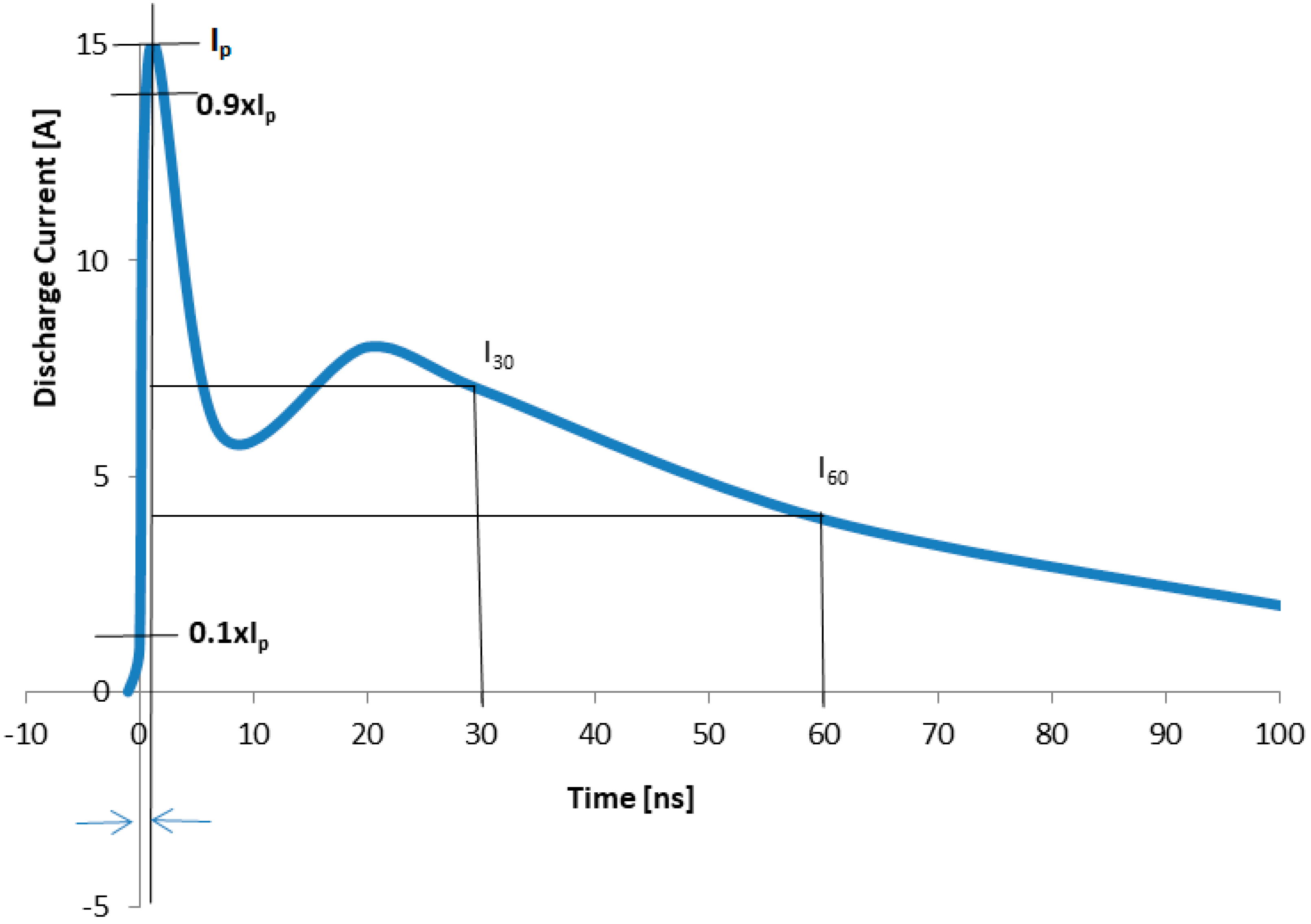
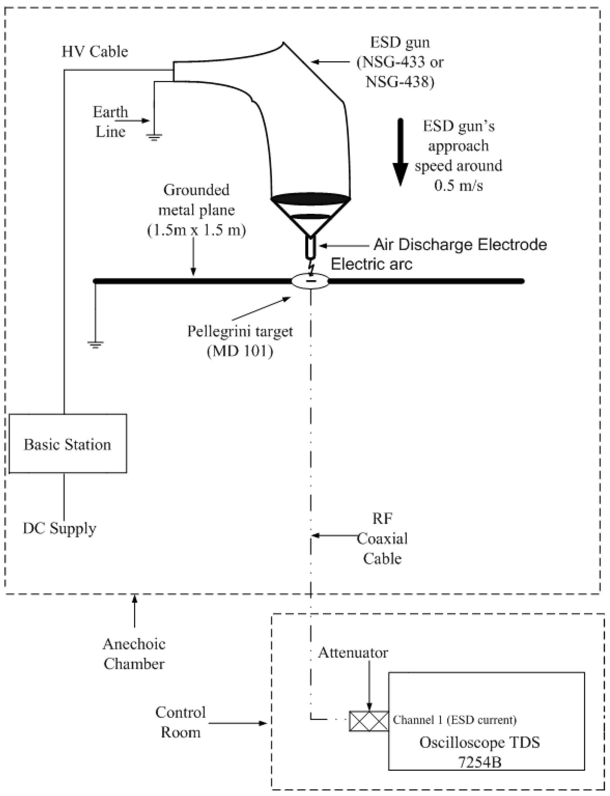
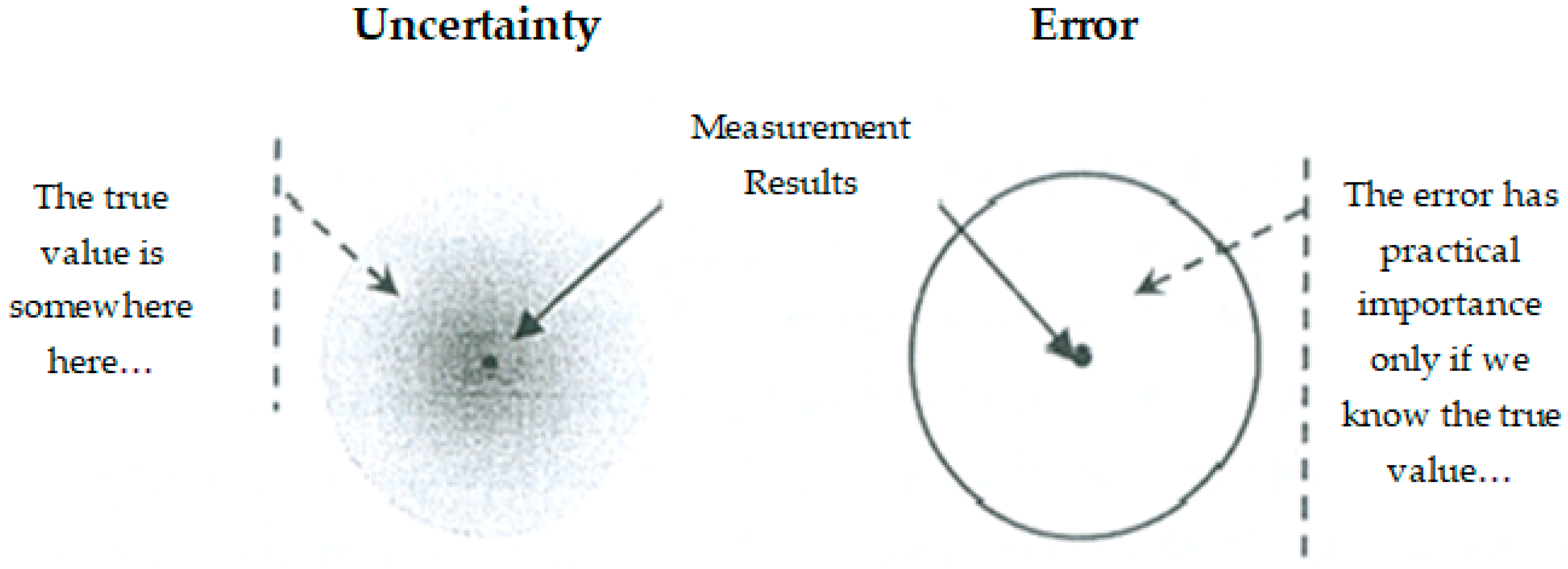

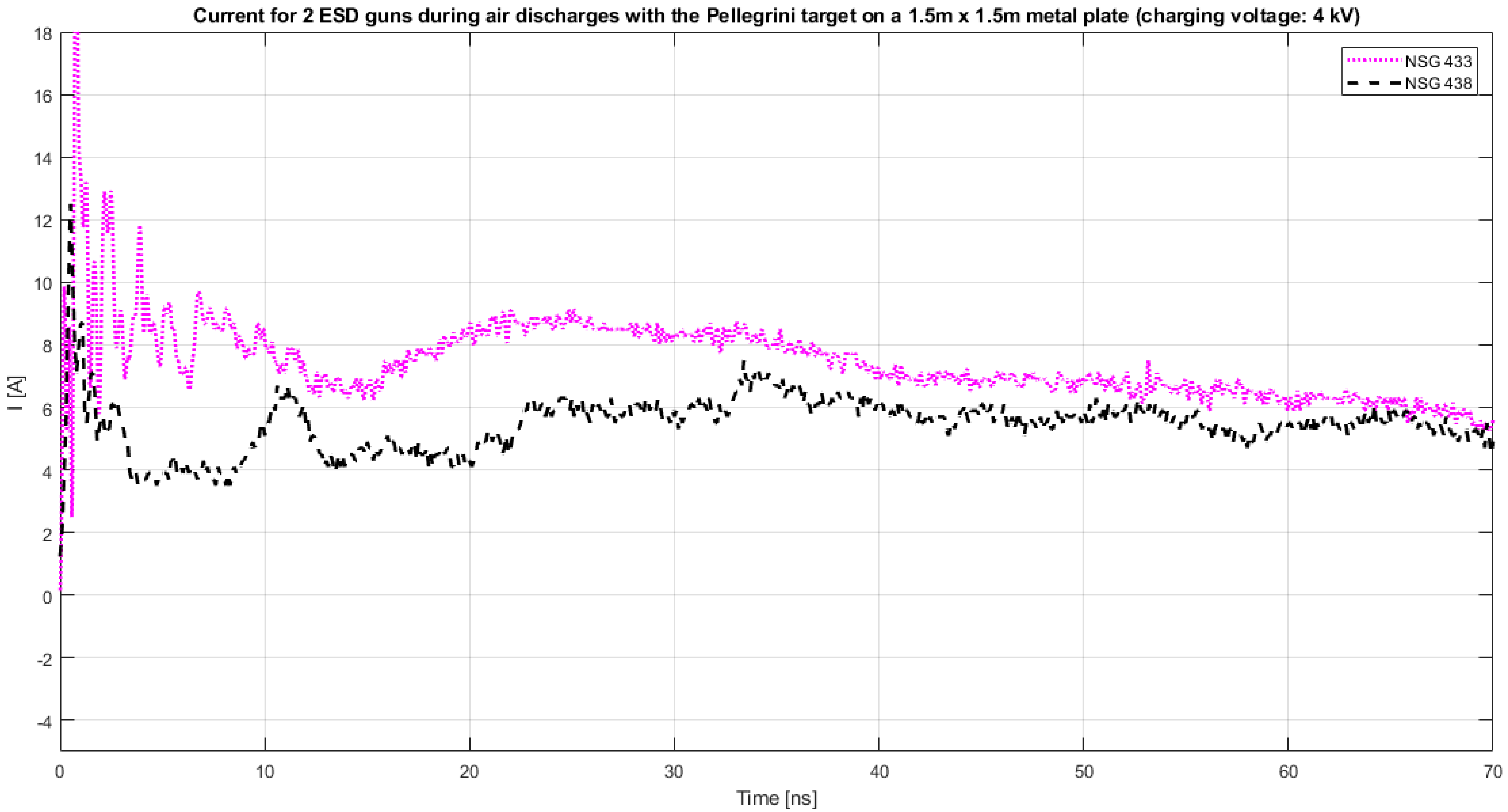

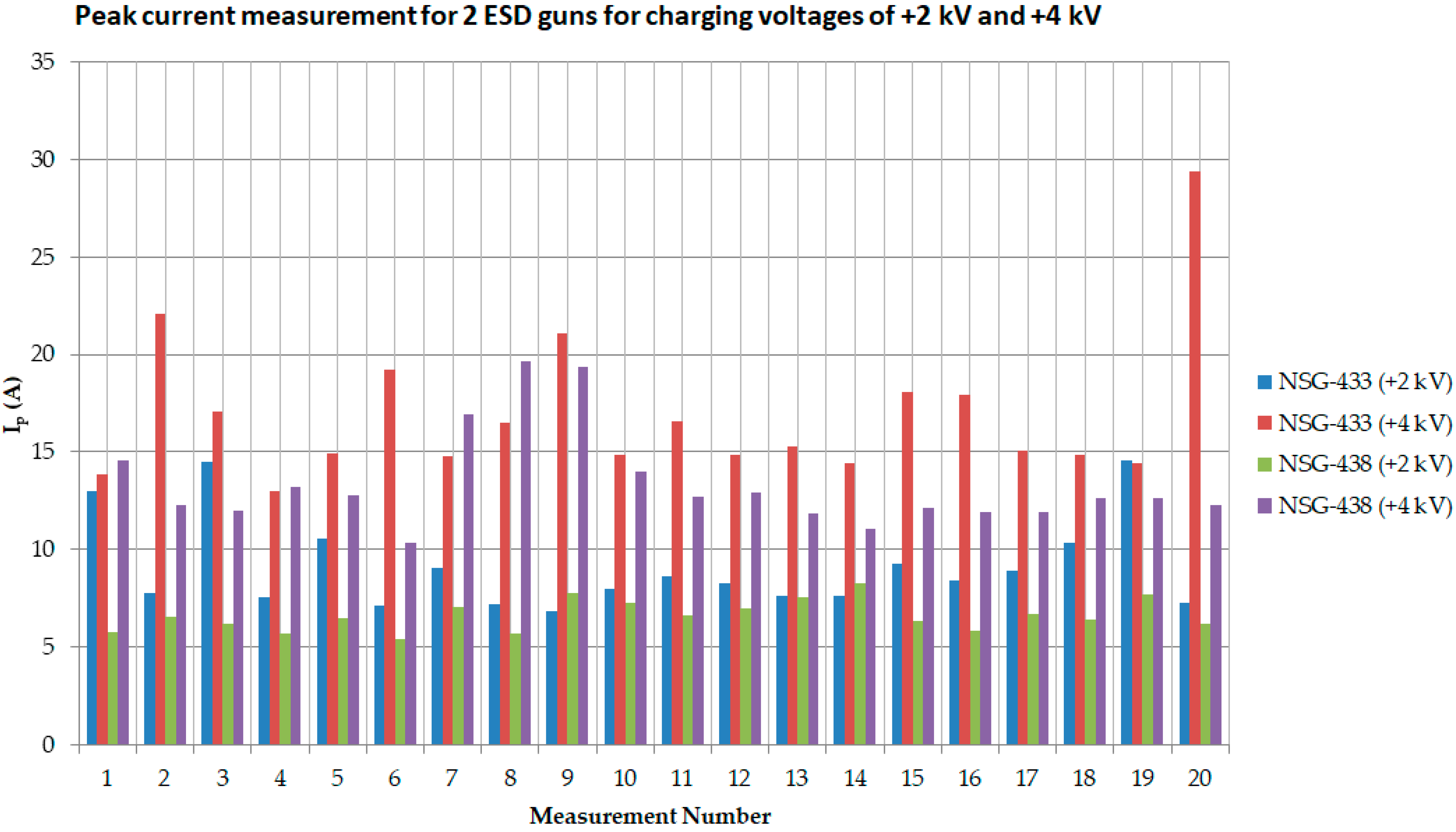

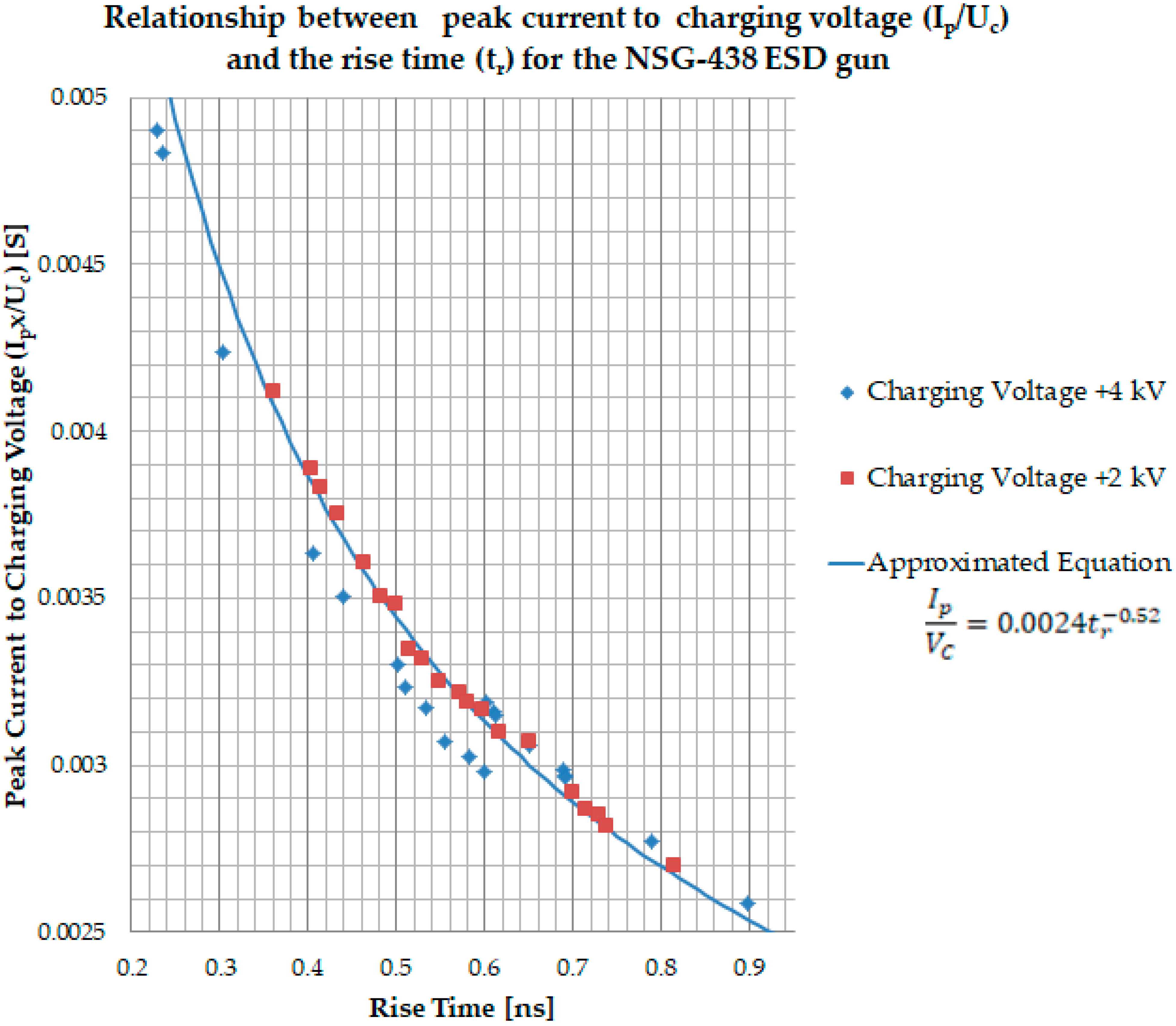
| Level | Charging Voltage (kV) | Ip (A) | Accepted Deviation | tr (ns) | Accepted Deviation | I30 (A) | Accepted Deviation | I60 (A) | Accepted Deviation |
|---|---|---|---|---|---|---|---|---|---|
| 1 | 2 | 7.5 | ±15% | 0.8 | ±25% | 4 | ±30% | 2 | ±30% |
| 2 | 4 | 15 | 8 | 4 | |||||
| 3 | 6 | 22.5 | 12 | 6 | |||||
| 4 | 8 | 30 | 16 | 8 |
| Measurement Number | NSG-433 | NSG-438 | ||||||
|---|---|---|---|---|---|---|---|---|
| +2 kV | +4 kV | +2 kV | +4 kV | |||||
| tr (ns) | Ip (A) | tr (ns) | Ip (A) | tr (ns) | Ip (A) | tr (ns) | Ip (A) | |
| 1 | 0.321 | 13.02 | 0.745 | 13.84 | 0.712 | 5.75 | 0.405 | 14.55 |
| 2 | 0.652 | 7.75 | 0.331 | 22.09 | 0.546 | 6.51 | 0.651 | 12.25 |
| 3 | 0.263 | 14.52 | 0.514 | 17.09 | 0.649 | 6.15 | 0.688 | 11.95 |
| 4 | 0.710 | 7.52 | 0.899 | 12.96 | 0.736 | 5.65 | 0.501 | 13.22 |
| 5 | 0.425 | 10.52 | 0.621 | 14.92 | 0.569 | 6.45 | 0.602 | 12.75 |
| 6 | 0.795 | 7.12 | 0.428 | 19.23 | 0.812 | 5.41 | 0.897 | 10.35 |
| 7 | 0.534 | 9.05 | 0.736 | 14.75 | 0.479 | 7.02 | 0.304 | 16.95 |
| 8 | 0.770 | 7.22 | 0.568 | 16.50 | 0.726 | 5.71 | 0.229 | 19.61 |
| 9 | 0.812 | 6.85 | 0.339 | 21.05 | 0.401 | 7.79 | 0.235 | 19.33 |
| 10 | 0.642 | 8.01 | 0.632 | 14.85 | 0.461 | 7.23 | 0.440 | 14.02 |
| 11 | 0.569 | 8.65 | 0.531 | 16.54 | 0.527 | 6.65 | 0.533 | 12.69 |
| 12 | 0.628 | 8.25 | 0.726 | 14.82 | 0.498 | 6.98 | 0.510 | 12.93 |
| 13 | 0.669 | 7.62 | 0.667 | 15.27 | 0.432 | 7.52 | 0.691 | 11.86 |
| 14 | 0.658 | 7.65 | 0.643 | 14.41 | 0.358 | 8.25 | 0.789 | 11.08 |
| 15 | 0.519 | 9.25 | 0.459 | 18.05 | 0.594 | 6.35 | 0.582 | 12.10 |
| 16 | 0.612 | 8.44 | 0.549 | 17.9 | 0.698 | 5.85 | 0.599 | 11.93 |
| 17 | 0.556 | 8.94 | 0.605 | 15.05 | 0.512 | 6.71 | 0.690 | 11.89 |
| 18 | 0.435 | 10.35 | 0.705 | 14.85 | 0.579 | 6.39 | 0.612 | 12.61 |
| 19 | 0.259 | 14.56 | 0.639 | 14.44 | 0.412 | 7.67 | 0.609 | 12.65 |
| 20 | 0.736 | 7.25 | 0.249 | 29.35 | 0.615 | 6.21 | 0.555 | 12.28 |
| Average Values | 0.578 | 9.13 | 0.579 | 16.90 | 0.566 | 6.61 | 0.556 | 13.35 |
| Standard deviation | 0.166 | 2.35 | 0.160 | 3.78 | 0.126 | 0.79 | 0.172 | 2.49 |
| Uncertainty Type A | 0.037 | 0.53 | 0.036 | 0.85 | 0.028 | 0.18 | 0.038 | 0.56 |
| Relative Uncertainty Type A (%) | 6.433 | 5.77 | 6.170 | 5.00 | 5.000 | 2.66 | 6.898 | 4.18 |
| Contributor | Distribution | Value (%) | Devisor | ui (%) | Source | |||||||||||
|---|---|---|---|---|---|---|---|---|---|---|---|---|---|---|---|---|
| NSG-433 | NSG-438 | NSG-433 | NSG-438 | NSG-433 | NSG-438 | |||||||||||
| 2 kV | 4 kV | 2 kV | 4 kV | 2 kV | 4 kV | 2 kV | 4 kV | 2 kV | 4 kV | 2 kV | 4 kV | |||||
| Type A | Repeatability | Normal | 5.77 | 5.00 | 2.66 | 4.18 | 1 | 5.77 | 5.00 | 2.66 | 4.18 | 33.29 | 25.00 | 7.08 | 17.47 | Table 2 |
| Type B | Vertical reading of oscilloscope’s indication | Normal | 0.82 | 2 | 0.41 | 0.17 | Certificate of calibration | |||||||||
| Measuring chain Pellegrini target-attenuator-cable | Normal | 1.04 | 2 | 0.52 | 0.27 | Certificate of calibration | ||||||||||
| Chain to oscilloscope failure | U shaped | 1.08 | 0.76 | 0.58 | Certificate of calibration | |||||||||||
| Approach to the target | Normal | 1.00 | 2 | 0.50 | 0.25 | Experience of the Lab | ||||||||||
| 34.56 | 26.27 | 7.66 | 18.74 | |||||||||||||
| Combined Standard Uncertainty UC (%) Equation (4) | 5.88 | 5.13 | 2.77 | 4.33 | ||||||||||||
| Expanded Uncertainty (for k = 2) U (%) Equation (5) | 11.76 | 10.26 | 5.54 | 8.66 | ||||||||||||
| Contributor | Distribution | Value (ps) | Devisor | ui (ps) | Source | |||||||||||
|---|---|---|---|---|---|---|---|---|---|---|---|---|---|---|---|---|
| NSG-433 | NSG-438 | NSG-433 | NSG-438 | NSG-433 | NSG-438 | |||||||||||
| 2 kV | 4 kV | 2 kV | 4 kV | 2 kV | 4 kV | 2 kV | 4 kV | 2 kV | 4 kV | 2 kV | 4 kV | |||||
| Type A | Repeatability | Normal | 37.20 | 35.74 | 28.29 | 38.36 | 1 | 37.20 | 35.74 | 28.29 | 38.36 | 1383.84 | 1277.35 | 800.32 | 1471.49 | Table 2 |
| Type B | Peak value reading | Normal | 50.00 | 2 | 25.00 | 625.00 | Uncertainty of Peak Value 3% | |||||||||
| Time I90 reading | Rectangular | 25.00 | 14.43 | 208.23 | Oscilloscope’s sampling rate 20 Gs/s | |||||||||||
| Time I10 reading | Rectangular | 25.00 | 14.43 | 208.23 | Oscilloscope’s sampling rate 20 Gs/s | |||||||||||
| Vertical reading of oscilloscope’s indication | Normal | 30.00 | 2 | 15.00 | 225.00 | Certificate of Calibration | ||||||||||
| Measuring chain cable—Attenuator—Pellegrini target | Normal | 30.00 | 2 | 15.00 | 225.00 | Certificate of Calibration | ||||||||||
| 2875.3 | 2768.81 | 2291.78 | 2962.95 | |||||||||||||
| Combined Standard Uncertainty UC Equation (4) | 53.63 | 52.62 | 47.87 | 54.43 | ||||||||||||
| Expanded Uncertainty (for k = 2) U Equation (5) | 107.26 | 105.24 | 95.74 | 108.86 | ||||||||||||
Publisher’s Note: MDPI stays neutral with regard to jurisdictional claims in published maps and institutional affiliations. |
© 2022 by the authors. Licensee MDPI, Basel, Switzerland. This article is an open access article distributed under the terms and conditions of the Creative Commons Attribution (CC BY) license (https://creativecommons.org/licenses/by/4.0/).
Share and Cite
Fotis, G.; Vita, V.; Maris, T.I. Rise Time and Peak Current Measurement of ESD Current from Air Discharges with Uncertainty Calculation. Electronics 2022, 11, 2507. https://doi.org/10.3390/electronics11162507
Fotis G, Vita V, Maris TI. Rise Time and Peak Current Measurement of ESD Current from Air Discharges with Uncertainty Calculation. Electronics. 2022; 11(16):2507. https://doi.org/10.3390/electronics11162507
Chicago/Turabian StyleFotis, Georgios, Vasiliki Vita, and Theodoros I. Maris. 2022. "Rise Time and Peak Current Measurement of ESD Current from Air Discharges with Uncertainty Calculation" Electronics 11, no. 16: 2507. https://doi.org/10.3390/electronics11162507
APA StyleFotis, G., Vita, V., & Maris, T. I. (2022). Rise Time and Peak Current Measurement of ESD Current from Air Discharges with Uncertainty Calculation. Electronics, 11(16), 2507. https://doi.org/10.3390/electronics11162507


