Article

Modeling and Simulation Analysis of Speed-Regulating Valve Flow Fluctuations under Differential Pressure Steps

1
Key Laboratory of Advanced Manufacturing and Intelligent Technology, Ministry of Education, Harbin 150080, China
2
School of Mechanical and Power Engineering, Harbin University of Science and Technology, Harbin 150080, China
3
School of Mechatronics Engineering, Harbin Institute of Technology, Harbin 150001, China
*
Author to whom correspondence should be addressed.
Electronics 2022, 11(16), 2580; https://doi.org/10.3390/electronics11162580
Submission received: 26 July 2022 / Revised: 12 August 2022 / Accepted: 16 August 2022 / Published: 18 August 2022
(This article belongs to the Section Systems & Control Engineering)

Abstract

:
As an important component of the movement speed adjustment components of the executive elements in a hydraulic system, the speed-control valve should have good dynamic response ability and dynamic and static flow stability. In the working state, due to the fluctuation of oil supply pressure, load variation, valve spool movement, force variation, etc., the pressure difference between the inlet and outlet of the speed-regulation valve is prone to a step response. Due to the nonlinear relationship between the flow and pressure, the phenomenon of instantaneous fluctuations in the controlled flow occurs, which in turn leads to the unstable phenomenon of the speed of the execution element. Based on the working principle of the internal core components of a speed-control valve with a pressure compensation function, this study establishes a dynamic mathematical model of the valve, which is analyzed using AMEsim software. Aiming at the key problem of sudden changes in the differential pressure steps, the characteristics of a speed-regulation valve are analyzed in relation to the differential pressure increment, spring stiffness, spring preload, and initial opening of the pressure compensator and its viscous damping coefficient. The influence of the above five variables on the flow fluctuation is studied and a reasonable parameter adjustment range is given. The simulation and analysis results provide strong theoretical support for the performance and parameter optimization configuration of the speed-regulation valve.

1. Introduction

As an important component of flow regulation in a hydraulic system, a speed regulation valve can avoid the controlled flow fluctuation caused by load changes and provide a stable feed speed for the actuator. The speed-regulation valve is composed of a differential pressure-reducing valve and a throttle valve in series. The throttle valve is used for the active regulation of the flow and the differential pressure-reducing valve is used for the passive regulation when the load changes. The two components combine with each other to control the flow and ensure that the flow is not affected by the load change, which plays a key role in ensuring the smooth movement speed of the actuator of the hydraulic system.
At present, the research directions of hydraulic valves are roughly as follows: one is the in-depth research on 2D valves conducted by Professor Ruanjian and co-workers of Zhejiang University of Technology specifically on the aspects of theory, structure, processing, application, dynamic characteristics, and control, but there are certain limitations in its promotion and application [1]. The other direction is a study on the slide valve and cone valve commonly used in industry. The current products have strong reliability. However, there is a lack of a specific design basis in terms of their design principles and the theoretical system is incomplete, which seriously restrict the further optimization of the performance and parameters of a hydraulic valve. The research is mainly focused on the valve’s core structure, dynamic characteristics, erosion, cavitation, and other aspects, with research on the sealing and temperature rise of the valve less common.
The main components that impact the performance of a hydraulic valve are its core, body, and seal. The valve’s core is directly related to the control of hydraulic oil and plays a key role in the control accuracy of the flow, pressure distribution, cavitation, stuck valve core, and other indicators. The internal flow passage of the valve body has a big influence on the flow field distribution of the hydraulic oil, and the deformation of its structure also has a big influence on the stress of the valve core. As one of the main causes of hydraulic valve failure, sealing performance is mainly affected by temperature, pressure, spool movement, and so on.
Yuanhaili analyzed the problem of the flow overshoot of the speed regulating valve being too large. By analyzing the opening degree of the throttle, the spring stiffness of the pressure-reducing valve, the spring preload shrinkage, and the size and gradient of the valve port area, she gave specific optimization parameters that effectively reduced the overshoot [2]. Zhang Jialin developed a proportional speed-regulating valve applied in a −40 °C low-temperature environment and gave the corresponding theoretical calculation, simulation, and experimental results of the design. The simulation only considered the effect of the temperature on the viscosity of the hydraulic oil and did not consider the effect of the temperature on the other factors. Therefore, in the experiment, the flow-regulation effect of the speed-regulating valve was poor in linearity, which was very different from the simulation results [3]. Liu established a detailed mathematical model for a proportional throttle cartridge valve and determined several factors affecting the performance of the throttle valve, which greatly improved its dynamic performance [4]. Chenqingtang collected and analyzed the vibration signals of a speed-regulating valve in different working states and established a time series AR (autoregressive) model to study the fault analysis and diagnosis of a speed-regulating valve, which opened up a new research idea for the fault diagnosis of a hydraulic system [5]. Li Lin Lin studied the erosion throttle valve damage caused by the pollutant particles in hydraulic oil and observed the influence of different shape factors on the erosion effect when the particle size was 0.5 mm [6]. Fales studied the problem of a slow flow response during the design and processing of a conical valve, analyzed the frequency characteristics, and optimized the design basis of a hardware and control system [7]. Songzilong optimized the hydraulic force of a slide valve, analyzed and studied the flow field of a non-full-circle opening and internal flow slide valve, and proposed to change the oil inlet into an inclined hole, and the optimization effect was optimal when the inclined angle was 15°~20° [8]. QUIN Long designed a pilot-controlled proportional directional valve with internal flow feedback, which integrated an internal feedback valve for the open loop and an electronic closed loop valve for the closed loop. The new valve greatly reduced the difficulty of using the directional valve and had excellent dynamic response characteristics [9]. Yuanwangbo studied the influence of the number of throttling slots on the thermal deformation of the spool valve. The research showed that the more the number of U-shaped throttling slots increased, the greater the type variable of the spool valve [10]. Zhaojinsong of Yanshan University studied the static and dynamic characteristics of an HSV-type high-speed switching digital valve; analyzed the factors affecting the opening/closing response times, the sizes of the saturation and dead zones, and the size of the output flow; and conducted experimental research on a high-speed switching digital valve characteristic test platform [11]. Jixingyu studied the proportional flow valve controller and dead time compensation strategy and proposed the dead time compensation strategy of bilinear interpolation, which greatly improved the hysteresis and linearity of the flow [12]. Zhaohaijuan used a valvistor flow valve as the research object, studied its dynamic and static flow characteristics by establishing a digital compensator, and improved the control performance of the flow valve under the compound control strategy [13]. Eriksson proposed the principle of a two-way valvistor proportional flow valve controlled by a double pilot valve with pressure difference compensation, studied the dynamic and static characteristics of the valve, and applied the valve to an electro-hydraulic system with independent control of the inlet and outlet to reduce the system energy consumption [14]. Lishengmao studied an ultra-high-pressure and large-flow-cartridge proportional flow valve and developed a flow valve with a maximum pressure of 105 MPa [15]. Amirante proposed a design method for reversing a spool valve, which effectively reduced the hydraulic force at the specified flow and the driving force of the spool valve [16]. Qiu Meng used a permanent magnet synchronous motor as the driving element of the throttle valve core of a speed-regulating valve and realized the technical scheme of digitizing the flow valve by improving the structure of the throttling groove [17]. Aiming at the problem of the difficulty in obtaining an effective mathematical model for the parameter selection of the commonly used empirical equation, Guo Zhijia established a two-dimensional model within the valve opening range for a simulation and fitted the obtained data to obtain the corresponding mathematical model, which provided a test basis for the flow characteristics of the valve [18]. Liuguoping et al. modeled and simulated a proportional flow valve, accurately measured its steady-state hydrodynamic force through experiments, and verified its open-loop step characteristics [19]. Min Cheng improved the dynamic performance of proportional valve compensation and established a mathematical model of an electro-hydraulic flow-matching energy-saving system. The new method effectively improved the speed control performance of the system [20].
At present, there is little research on the problem of valve output flow fluctuations caused by a change in the differential pressure of a speed-regulating valve. Whether the flow is stable plays a vital role in the smooth operation of the actuator. This paper studies the influence of multiple parameters on the valve output flow fluctuation under the changes in the differential pressure at the inlet and outlet of the speed-regulating valve and provides a theoretical basis for the performance and parameter optimization of a speed-regulating valve with a pressure compensation function.

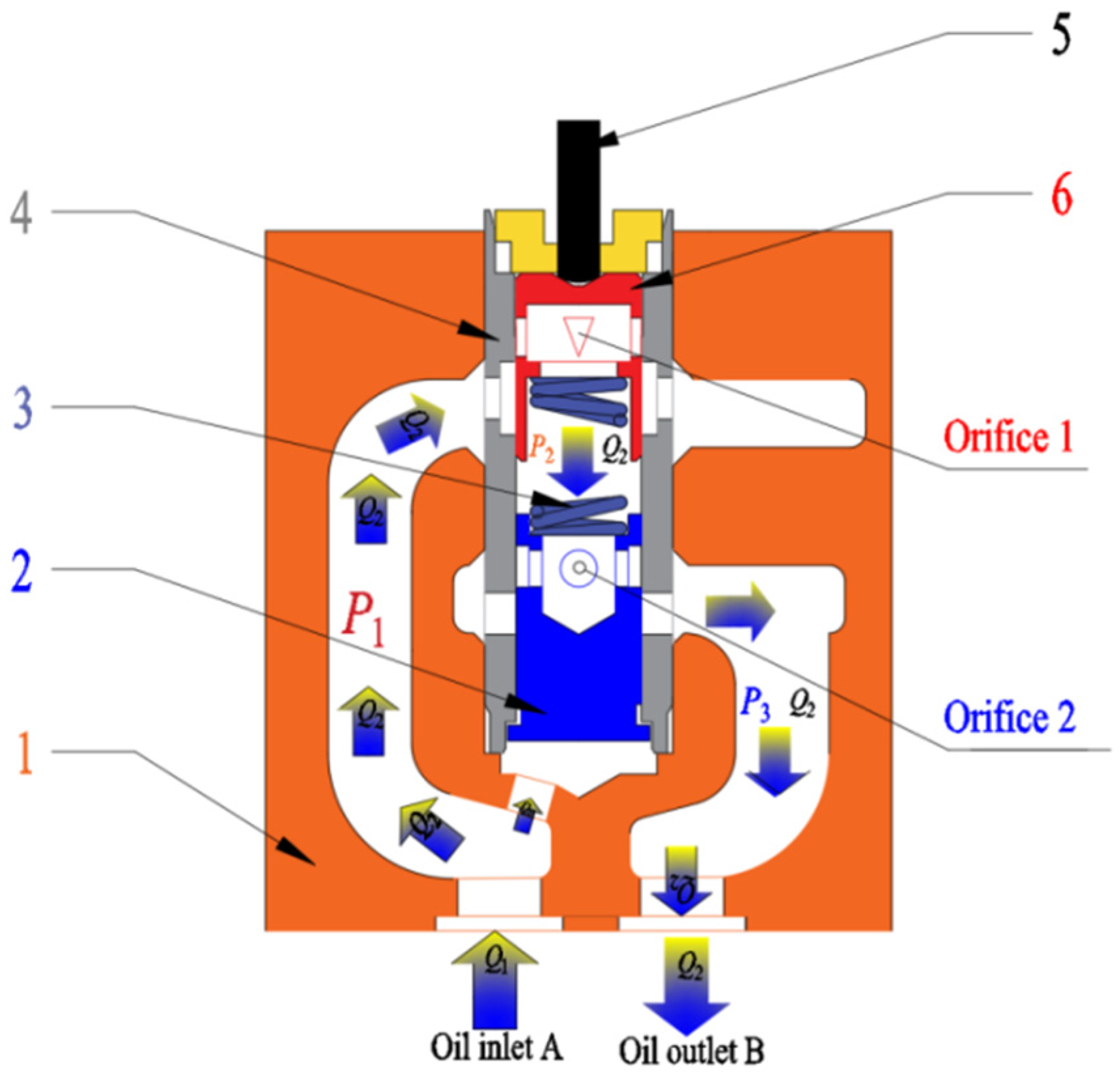
2. Structure and Working Principle of Speed-Regulation Valve

As shown in Figure 1, this valve is used in a hydraulic system to adjust the flow when the hydraulic oil enters from inlet A through throttle port 1, which achieves the active adjustment of the flow, and then flows through throttle port 2, controlled by the pressure compensator in valve body outlet B. When the load fluctuation, can produce oil in and out of the mouth, the change of pressure difference, pressure difference between in and out of the oil outlet change will flow hole through the inlet to the direct effect on the bottom of the pressure compensator and pressure compensator force balance of the original break, and thus the displacement control of circular orifice throttling area change, achieve flow dynamic secondary regulation.
As shown in Figure 2, the dynamically adjusted flow through throttle port 1 and the pressure compensator stabilize at a fixed value that is not affected by the load changes, thus achieving a stable flow output.
The pressure compensator is sensitive to the change in the pressure difference. The change in the pressure difference causes the displacement of the pressure compensator and then causes the changes in the throttling area to achieve the purpose of flow-rate regulation. When the load increases, the oil outlet pressure increases, and the differential pressure of the speed-regulating valve in and out of the mouth decreases, resulting in a reduced flow rate. However, the minor pressure difference can lead to the pressure compensator having an unbalanced force, and the spring in the pressure compensator balances and elongates at the same time. The pressure compensator of the throttling area then increases the flow rate back to the front where the load change forms. The reduced load reduces the pressure in the oil outlet, and the differential pressure in and out of the mouth of the speed-regulating valve increases, which leads to the increase in traffic. At this time, due to the increased pressure difference, the pressure compensator moves in the direction of the spring, further making smaller pressure compensations in the throttling mouth area before the implementation flow rate decreases and the load changes.

3. Establishment of Mathematical Model of Speed-Regulation Valve

3.1. Flow Rate Analysis

According to the working principle of the speed-regulation valve, the hydraulic oil flows from the inlet into the valve chamber through the throttle valve port and out through the oil outlet through the throttle valve port of the pressure compensator without considering leakage. Another part of the flow rate controls the size of the valve chamber of the pressure compensator and then adjusts the opening of the valve core of the pressure compensator. Its flow-rate equation is
Q 1 = Q H + Q 2
where
Q1—Inlet flow rate of speed-regulation valve L/min
QH—Pressure compensator cavity flow rate variation L/min
Q2—Outlet flow rate of the speed-regulation valve L/min
The flow rate into the pressure compensator cavity is
Q H = x ˙ 2 A 2 2 Q h
Qh—Flow-rate change due to liquid compression L/min
It can be approximated as
Q H = x ˙ 2 A 2 2
Among them, the flow rate Qh change caused by the hydraulic oil compression in the sealing chamber of the pressure compensator is small and can be ignored. Without considering leakage, according to the flow rate continuity equation, the throttle valve port flow rate, pressure compensator throttle port flow, and oil outlet flow should be equal so the corresponding equation is
Q 2 = C d W 1 x 1 2 ( p 1 p 2 ) ρ = C d W 2 x 2 2 ( p 2 p 3 ) ρ
x1—Displacement of the throttle valve core m
x2—Displacement of the valve element of the pressure compensator m
A21—Area of the upper end of the pressure compensator mm2
A22—Lower end area of the pressure compensator mm2
Cd—Flow coefficient of the speed-regulation valve
W1—Area gradient of the throttle valve port m
W2—Area gradient of the pressure compensator valve port m
p 2 = p 3 + ρ 2 ( Q 2 C d W 2 x 2 ) 2
Q 1 = x ˙ 2 A 2 2 + C d W 2 x 2 2 ( p 2 p 3 ) ρ
p 2 = p 3 + ρ 2 ( Q 1 x ˙ 2 A 22 C d W 2 x 2 ) 2

3.2. Dynamic Balance Equation of Valve Elements

According to the dynamic change of pressure compensator in the mediation process, the equation can be obtained as follows:
p 1 A 22 = p 2 A 21 + N 0 + K ( x 2 x 1 ) + B 2 x ˙ 2 + m 2 x ¨ 2
N0—Spring preload N
K—Spring stiffness N/m
B2—Transient hydrodynamic damping coefficient (N/s)/m
m2—Mass of the pressure compensator kg
p 1 A 22 2 = p 2 A 21 A 22 + N 0 A 22 + K ( x 2 x 1 ) A 22 + B 2 x ˙ 2 A 22 + m 2 x ¨ 2 A 22
Bring Equation (3) into the above equation to obtain
p 1 A 22 2 = p 2 A 21 A 22 + N 0 A 22 + K ( x 2 x 1 ) A 22 + B 2 ( Q 1 Q 2 ) + m 2 x ¨ 2 A 22
when A21 and A22 of the speed-regulation valve are equal, the above equation shall be further sorted out:
p 1 A 22 2 = p 2 A 22 2 + N 0 A 22 + K ( x 2 x 1 ) A 22 + B 2 ( Q 1 Q 2 ) + m 2 x ¨ 2 A 22
Bring Equation (7) into the above equation to obtain
p 1 A 22 2 = ( p 3 + ρ 2 ( Q 1 x ˙ 2 A 22 C d W 2 x 2 ) 2 A 22 2 + N 0 A 22 + K ( x 2 x 1 ) A 22 + B 2 ( Q 1 Q 2 ) + m 2 x ¨ 2 A 22
( p 1 p 3 ) A 22 2 = ρ 2 A 22 2 ( Q 1 x ˙ 2 A 22 C d W 2 x 2 ) 2 + N 0 A 22 + K ( x 2 x 1 ) A 22 + B 2 ( Q 1 Q 2 ) + m 2 x ¨ 2 A 22
Δ p A 22 2 = ρ 2 A 22 2 ( Q 1 x ˙ 2 A 22 C d W 2 x 2 ) 2 + N 0 A 22 + K ( x 2 x 1 ) A 22 + B 2 ( Q 1 Q 2 ) + m 2 x ¨ 2 A 22
where Δ p refers to the differential pressure of the speed-regulation valve
Q 2 = Q 1 + 1 B 2 ( ρ A 22 2 2 ( Q 1 x ˙ 2 A 22 C d W 2 x 2 ) 2 + N 0 A 22 + K ( x 2 x 1 ) A 22 + m 2 x ¨ 2 A 22 Δ p A 22 2 )
A further arrangement can be obtained:
Q 2 = Q 1 1 B 2 [ Δ p A 22 2 ρ 2 ( Q 1 x ˙ 2 A 22 C d W 2 x 2 ) 2 A 22 2 N 0 A 22 K A 22 ( x 2 x 1 ) m 2 x ¨ 2 A 22 ]
According to the above equation, the outlet flow fluctuates around Q1, and the outlet flow rate is determined by the coupling of parameters such as the viscous damping coefficient B2, differential pressure, pressure compensator area A, spring stiffness K, and the pressure compensator opening. The existence of a viscous damping coefficient will weaken the influence of the pressure difference, pressure compensator area, and spring stiffness on the flow fluctuation.
When the flow is stable, the stable flow is:
Q 0 = Q 1 1 B 2 [ Δ p 0 A 22 2 ρ 2 ( Q 1 C d W 2 x 2 ) 2 A 22 2 N 0 A 22 K A 22 ( x 20 x 1 ) ]
where
Q0—Flow rate when the differential pressure of the speed-regulation valve is stable L/min
Δ p 0 —Differential pressure when the governor valve is stable MPa
Therefore, the flow rate fluctuation is
Δ Q = 1 B 2 [ Δ p 0 A 22 2 ρ 2 ( Q 1 C d W 2 x 2 ) 2 A 22 2 N 0 A 22 K A 22 ( x 20 x 1 ) ] 1 B 2 [ Δ p A 22 2 ρ 2 ( Q 1 x ˙ 2 A 22 C d W 2 x 2 ) 2 A 22 2 N 0 A 22 K A 22 ( x 2 x 1 ) m 2 x ¨ 2 A 22 ]
Δ Q = 1 B 2 [ ( Δ p 0 - Δ p ) A 22 2 + ρ 2 A 22 2 ( ( Q 1 x ˙ 2 A 22 C d W 2 x 2 ) 2 ( Q 1 C d W 2 x 2 ) 2 ) K A 22 Δ x 20 ]
where
Δ x 20 —Displacement of the pressure compensator m
Δ Q —Flow-rate fluctuation L/min
From the above equation, it can be seen that the fluctuation of the flow rate is related to many factors, such as the viscous damping coefficient, differential pressure, the bottom area of the pressure compensator, oil density, spool displacement, spring stiffness, the opening of the pressure compensator, etc., and is the result of multi-factor coupling. Considering that the velocity x ˙ 2 of the spool displacement is small when the pressure compensator is adjusted, the above equation can be simplified to
Δ Q = 1 B 2 [ ( Δ p 0 - Δ p ) A 22 2 K A 22 Δ x 20 ]
When the pressure difference ΔP is negative, that is, when the inlet pressure is lower than the outlet pressure, the displacement of the pressure compensator will become a negative value; the spool moves downward, and the flow rate fluctuates, with a tendency to increase at this time. The change in its value depends on the displacement x20 of the pressure compensator under the pressure difference and spring action. Then, the flow rate affected by the difference between ΔP0 and ΔP can be summed to obtain the effect of the pressure difference on the flow-rate fluctuation.
The spring stiffness not only affects the flow rate in its equation but also further affects the flow-rate fluctuation by affecting the spool displacement and spool speed. The spring stiffness should not be too small. If it is too small, the pressure compensator will not work. Generally, the spring stiffness has little effect on the speed so the flow-rate fluctuation increases with the increase in the spring stiffness.
It can be seen in the above equation that properly increasing the viscous friction coefficient can effectively avoid the flow-rate fluctuation.

4. Simulation Analysis of Working State of Speed-Regulation Valve

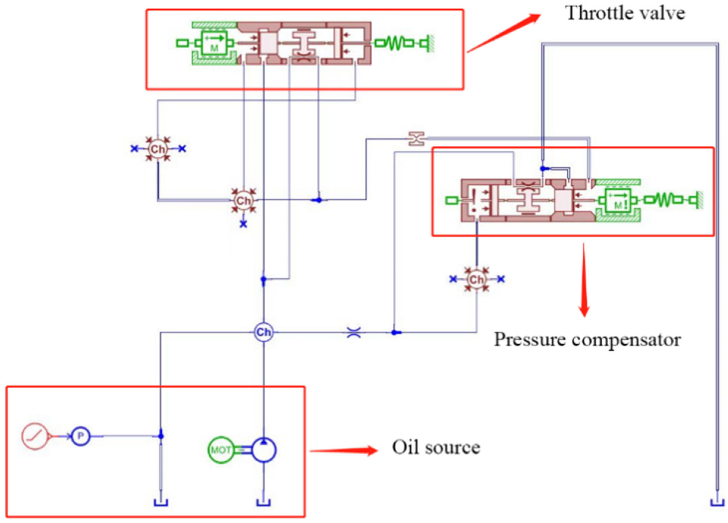
4.1. AMEsim Model Building

The AMEsim simulation model was built according to the design structure of the speed-regulation valve and the working principle of the speed-regulation valve. The known design parameters of the valve were put into the model and the dynamic simulation was carried out. Simulation parameters are shown in Table 1.
As shown in Figure 3, the speed-control valve simulation model was mainly composed of three parts: the oil source, the throttle valve, and the pressure compensator, as well as other auxiliary components. The throttle valve and pressure compensator were the main body of the governor valve. When verifying the basic performance of the flow-pressure difference of the speed-regulating valve, the oil supply in the simulation was from a constant displacement pump in parallel with the pressure source, and the outlet of the valve was directly connected with the oil tank to ensure that the pressure difference between the inlet and outlet of the speed-regulation valve was always determined by the pressure source. The effect of the pressure difference change before and after the speed-regulation valve on the flow was then simulated.
After throttle valve spool 6 of the speed-control valve is set, the displacement of the spool should no longer change. Therefore, when modeling, the throttle valve spool was directly fixed, and the opening degree needed to be adjusted directly to avoid a situation where the preload force of the spring also changed when adjusting the opening degree of the valve core. The different variables of the speed-regulating valve were studied.

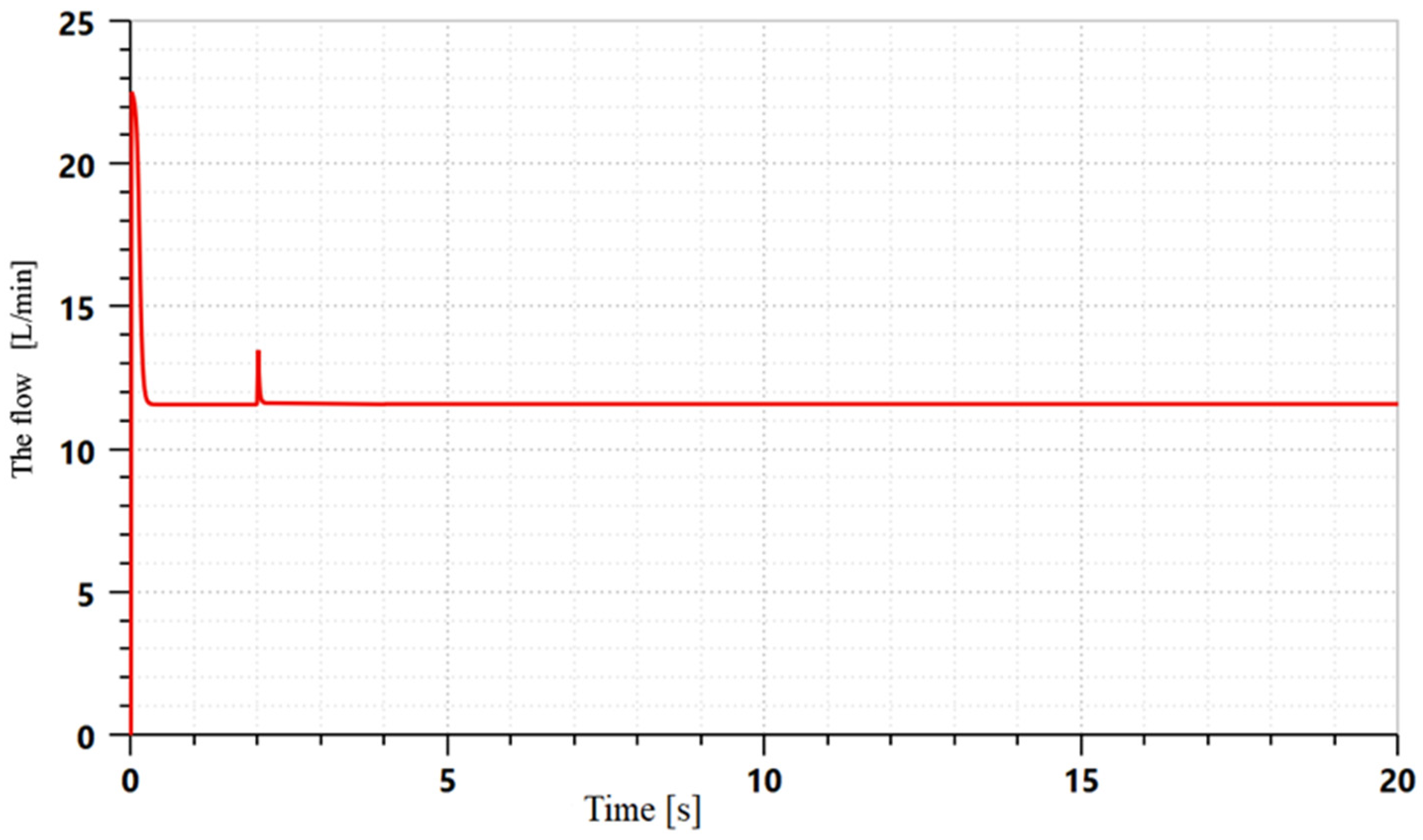
4.2. Differential Pressure and Flow-Rate Analysis of Inlet and Outlet of Governor Valve

The fluctuation of the flow rate in the outlet of the speed-control valve can produce valve vibration and noise, which directly affects the stability of the actuator and is extremely detrimental to the flow-rate control accuracy of the speed-control valve. When the load changes abruptly, it is very easy to generate pressure difference fluctuations in the hydraulic system, and the fluctuations in the pressure difference between the inlet and outlet of the speed-control valve can cause flow shocks in the hydraulic components, and cavities and negative pressures in the flow field inside the hydraulic components are easily generated. The deterioration of the erosion effect can seriously damage the life of the components used in a hydraulic system. Therefore, a pressure compensation device should be used to reduce the peak of the flow rate fluctuation as much as possible.
The initial pressure difference of the speed-regulating valve was set to 2 MPa, and when it suddenly increased to 4 MPa after 4.5 s of stabilization, the spring stiffness was set to 20 N/mm and the spring preload was set to 0.1 N for the preliminary simulation. It can be seen in Figure 4 that the flow rate suddenly increased in a short period of time and then returned to the initial equilibrium state with the adjustment of the spool position of the pressure compensator.
During the initial transient state of the differential pressure change, the valve experiences a flow-rate overshoot phenomenon, at which time the flow rate is much higher than the control flow rate. The step flow rate in the initial state often occurs in an environment without hydraulic oil. When the valve is not connected with hydraulic oil, the valve cavity is mainly occupied by air and its pressure is much lower than the pressure generated by the hydraulic system. At the same time, due to the existence of the flow rate in the cavity, this increases rapidly so that the hydraulic oil fills the hydraulic system and as the air in the hydraulic system is removed, the flow rate quickly returns to a balanced state.
After a brief flow-rate overshoot period, the flow rate reached equilibrium at a fixed differential pressure. When the pressure difference before and after the speed-control valve was suddenly changed in 4.5 s, the flow rate fluctuated again because at this time, the system was full of hydraulic oil, there was a certain pressure, the flow rate peak was small, and the fluctuation time was much lower than the initial peak flow rate. At the same time, the displacement curve of the pressure compensator also produced a small step, indicating that the pressure compensator had a very high sensitivity in its flow-rate adjustment, produced short-term fluctuations in the flow rate, and its flow rate back to a stable state was related to the pressure compensator.

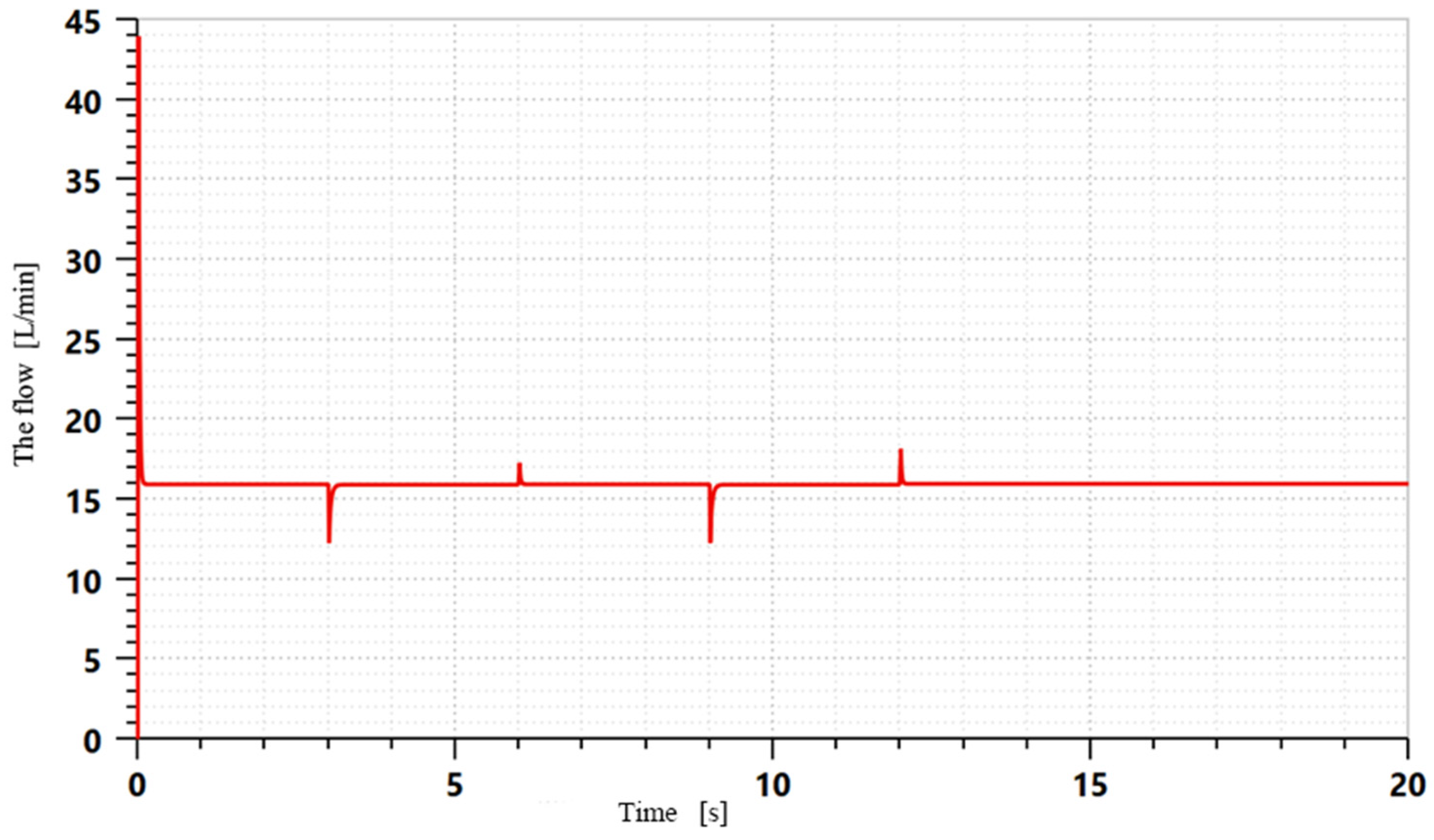
4.3. Influence of Differential Pressure on Flow Rate

The initial pressure difference was set at 2 MPa and run for 2 s and then the pressure difference was suddenly increased to 6 MPa and then continuously increased to 10 MPa within 2 s. The simulation test curve is shown in Figure 5. It can be seen that with the same incremental pressure difference change, only the step pressure difference caused the flow to fluctuate, and the flow rate was not affected by the continuous pressure difference changes.
When the throttle port of the speed-regulation valve was adjusted, the flow-rate fluctuation was mainly caused by the step change in the load, which led to the change in the pressure of the inlet and outlet of the speed-regulation valve, resulting in the step change in the pressure difference. When the pressure difference changed continuously, the flow rate in the pressure compensator did not change and did not adversely affect the valve, hydraulic cylinder, and other hydraulic components in the hydraulic system.

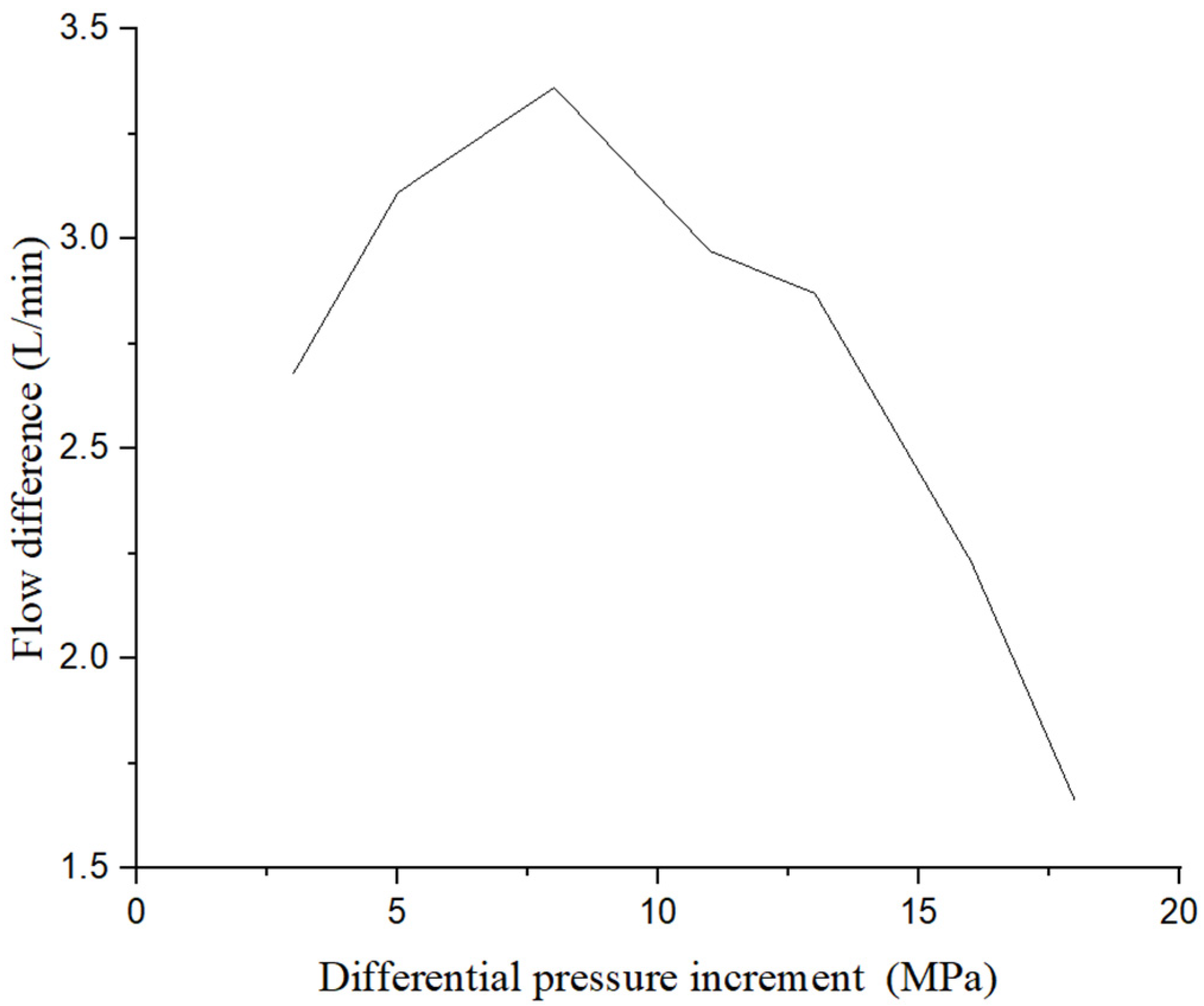
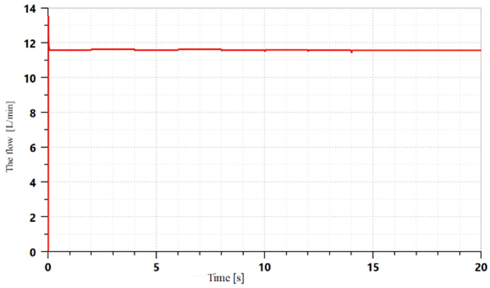
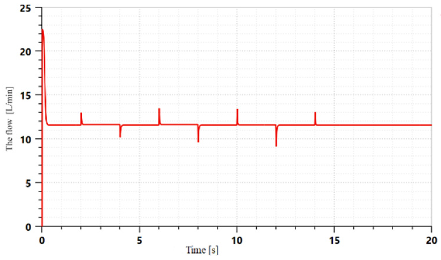
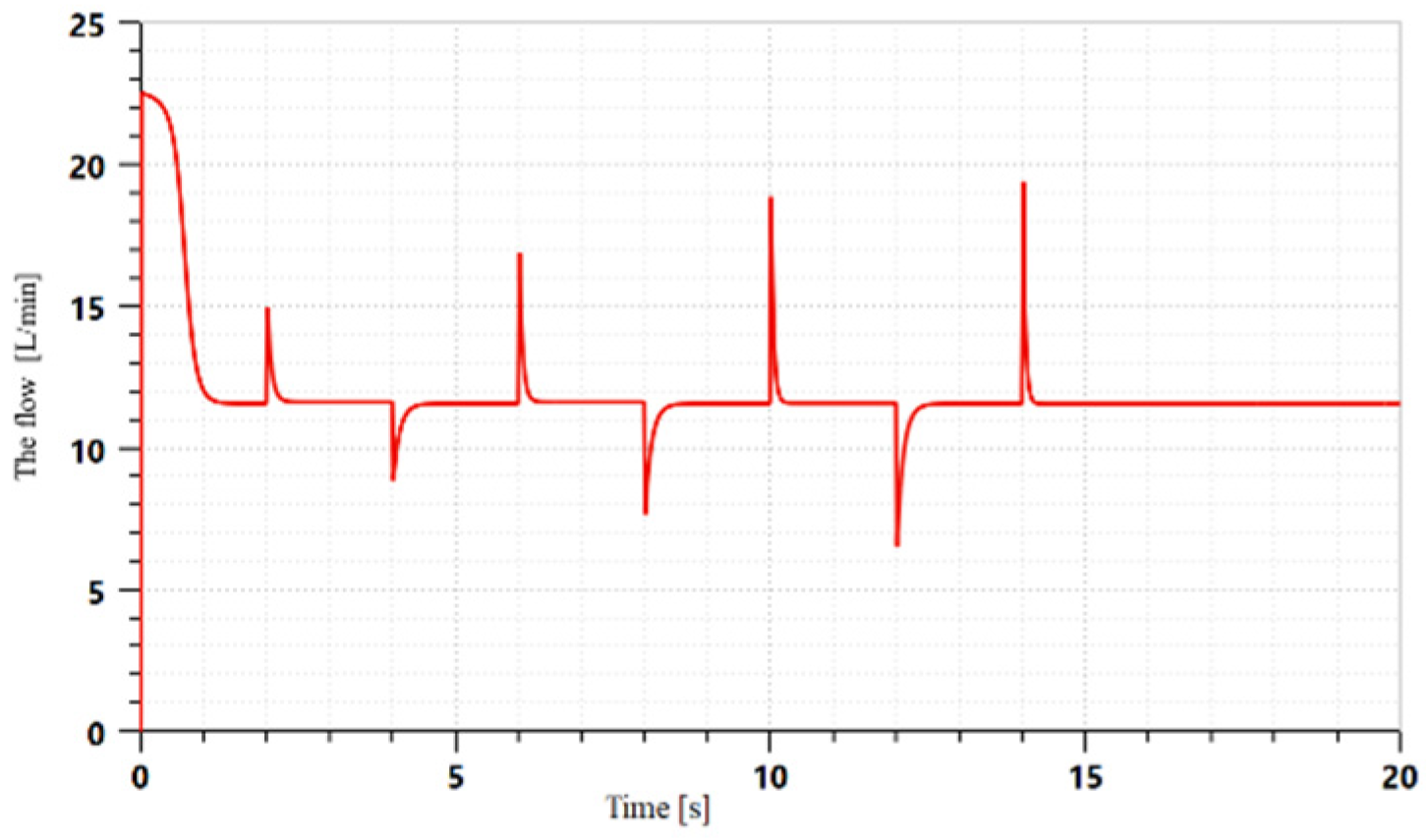
4.4. Influence of Differential Pressure Increment Change on Flow-Rate Change

The initial pressure was set at 21 MPa, then it was changed to 2 MPa after 3 s, and then to 21 MPa after 3 s for the simulation test. The simulation test curve is shown in Figure 6.
It can be seen in Figure 6 that the peak value of the flow-rate fluctuation was determined by the pressure difference increment. Under the same pressure difference, the flow-rate fluctuation generated by the negative pressure difference was larger than that generated by the positive pressure difference. It can be seen in the figure that when the step from 21 MPa to 2 MPa was taken, the flow rate dropped sharply from 15.93 L/min to 12.28 L/min and recovered to 15.91 L/min within 0.1 s. From 6 s, when the differential pressure step was taken back to 21 MPa, it could be seen that there would have still been a flow-rate fluctuation. The flow rate increased sharply from 15.91 L /min to 17.27 L/min and reached equilibrium again after 0.5 s. The flow rate at equilibrium was 15.93 L /min. The pressure difference was set to 2 MPa again, and the pressure difference was increased to 10 MPa after equilibrium. Under the action of the positive pressure difference, it could be seen that the flow rate fluctuated again and the peak of the flow rate reached 19.24 L/min. When the pressure difference increased to 21 MPa and 10 MPa under 2 MPa, the peak value did not increase with the increase in the pressure difference, and the wave peak of flow rate was not positively correlated with the increase in the pressure difference.
It can be seen in Figure 7 and Table 2 that the flow-rate fluctuation was the largest when the flow-rate pressure difference increment was 8 MPa, and the flow-rate fluctuation tended to zero when the pressure difference was too large, which can be verified with the equation. The flow-rate fluctuation value was not directly proportional to the pressure difference.

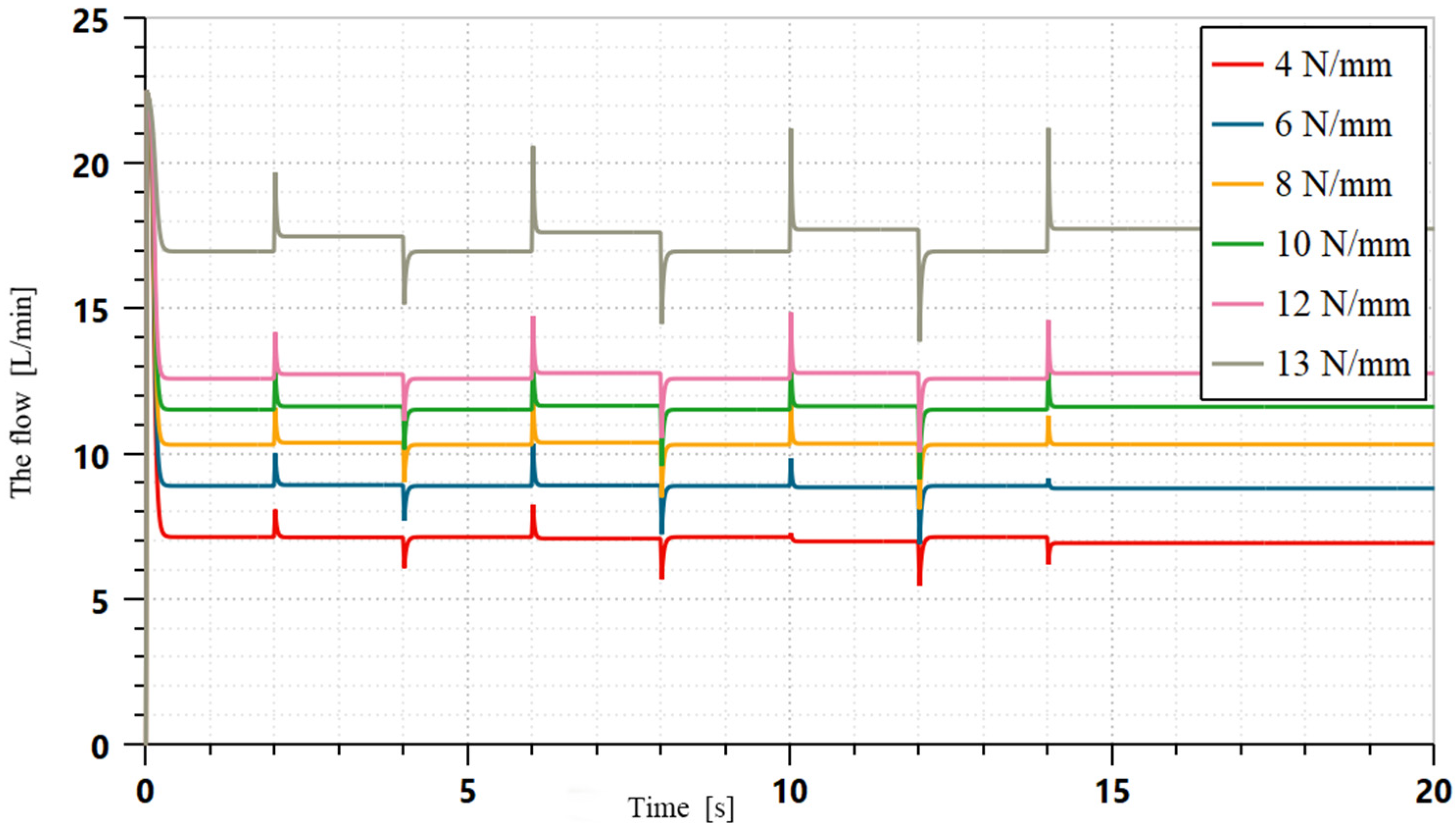
4.5. Effect of Spring Stiffness on Flow-Rate Fluctuation

The spring stiffness coefficient is the key factor affecting the speed-regulating valve. Whether its size is properly selected will directly determine whether the function of the speed-regulating valve can be realized and whether the response of the speed-regulating valve is sensitive. The spring preload directly affects the performance index of the valve. The spring preload was set at 0.1 N and the opening of the throttle port was set at the fully open position to ensure the normal assembly of the throttle valve spool and the pressure compensator. The initial impact of the pressure compensator was weakened as far as possible to observe the influence of the spring stiffness on the flow rate of the speed-regulation valve.
Spring stiffness in a certain range did not affect the flow-rate peak size and only affected the size of the steady flow rate and the first wave peak value. After exceeding a certain value, the flow rate was not stable and not up to the requirements of the governor valve crest increases with the increase in the pressure difference.
The characteristics of the effect of the spring stiffness on the flow-rate fluctuation can be roughly divided into three ranges and corresponding curves are selected as representatives according to the different characteristics, as shown in Figure 8. It can be seen that when the throttle valve opening degree was maintained at a certain level, the steady flow rate continued to increase with the increase in the spring stiffness, and the wave peak of the flow rate generally showed an increasing trend.
When the spring stiffness ranges from 0.1 to 3 N/mm, the simulation results are shown in Figure 9, the fluctuation of the flow rate was ideal under the condition of a small fluctuation in the pressure difference, and there was not be a large peak value. However, with the increase in the pressure difference, the flow rate changed with the change in the pressure difference, which was not able to meet the basic requirements of the flow rate not changing with the pressure difference. At the same time, with the increase in the negative pressure difference, the flow rate fluctuated greatly and the flow rate was zero. In this case, it was very easy to produce unfavorable flow-rate field conditions such as flow-rate discontinuity and cavitation.
The spring stiffness ranges from 3 N/mm to 12 N/mm, and the simulation results are shown in Figure 10. When the pressure was balanced, the flow rate did not change with the pressure difference and the flow-rate peak was large but in a stable state. When the spring stiffness was about 6 N/mm, the flow-rate fluctuation was not only stable within 1.5 L/min but there was also a trend in the flow-rate fluctuation decreasing with the increase in the pressure difference.
When the spring stiffness was more than 12 N/mm, compared with the flow-rate fluctuation of 3~12 N/mm in Figure 11, it can be seen that the flow-rate fluctuation was stable, its peak value was relatively large, and the flow rate changed with the change in the pressure difference. No longer meeting the basic requirements of the governor valve, the wave peak increased with the increase in the flow rate. To sum up, when the spring stiffness is preloaded with 0.1 N and the valve opening degree is 2 mm, it can be concluded that the range of the preloaded force should be within 3~12 N/mm and factors such as preloaded force and valve opening degree should be further optimized.
Compared with the derived mathematical model, it can be seen that the simulation results verify the correctness of the new speed-regulation valve model with the pressure compensation function.

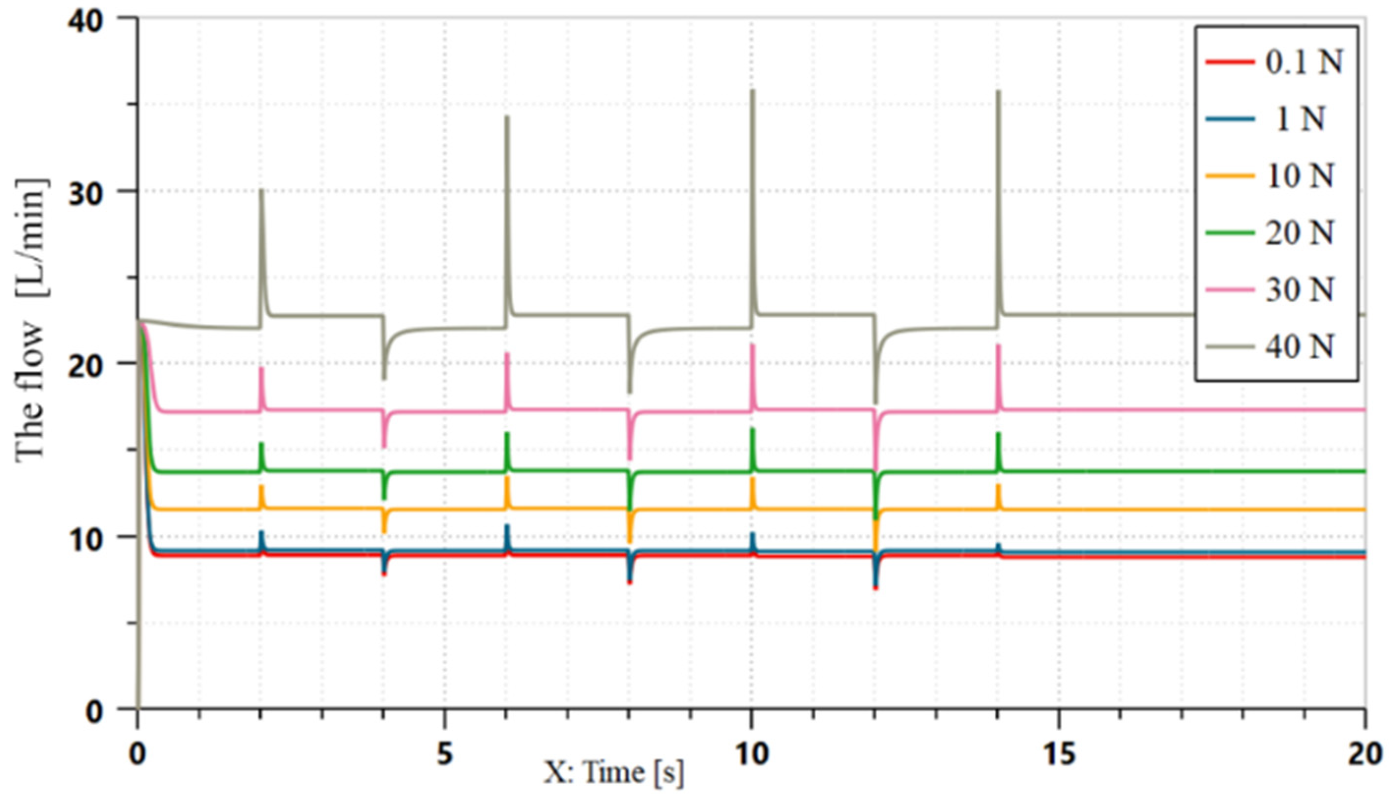
4.6. Effect of Spring Preload on Flow-Rate Fluctuation

The spring preload not only affects the performance of the speed-regulation valve but from an assembly point of view, there is a certain preload between the throttle valve and the pressure compensator that can not only improve the precision of the speed-regulation valve but also improve the response frequency of the valve. Too little spring preload affects the compactness of the valve and too much directly affects its assembly accuracy.
Taking a spring stiffness of 6 N/mm and valve opening of 2 mm as the conditions, the influence of spring preload on the flow-rate fluctuation was further discussed. The simulation test results are shown in Figure 12.
As can be seen in Figure 12, with the increase in the spring preload, the steady flow rate continued to increase and the initial wave peak of the flow rate continued to decrease. It can be seen in Figure 12 that the smaller the preloading force of the spring, the smaller the fluctuation of the flow rate when the pressure difference changed and the faster the recovery speed. When the preload increased to a certain value, the flow rate changed with the pressure difference and the peak value also increased. In terms of the stability of the peak value, the preloading force should not exceed 30 N. After the preloading force exceeds 30 N, the fluctuation of the flow rate will be too large, the flow rate will change with the change in the pressure difference, and the adjustment speed will be slow when the flow rate returns to a stable state.
To sum up, the value range of the speed-regulating valve spring preload should be as large as possible to ensure that within 0.1 N/mm~40 N/mm, the flow rate in this range will not change because of pressure differences and the flow-rate fluctuation is stable.

4.7. The Effect of Initial Opening of Pressure Compensator on Flow-Rate Fluctuation

When the opening degree of the throttle port was set at 2 mm, the spring preload was set at 6 N/mm, and the spring preload was set at 10 N, the pressure compensator was adjusted to study the different initial opening degrees. The simulation test results are shown in Figure 12.
It can be seen in Figure 13 that the initial wave peak of the flow rate at different opening degrees was the same. With the increase in the opening degree of the pressure compensator, the balance flow rate gradually increased and the fluctuation of the flow rate decreased with the increments of the pressure differences. When the initial opening was less than 1 mm, the pressure difference increased from 2 MPa to 10 MPa after more than 8 MPa and the wave peak of the flow rate appeared to be negative. The pressure compensator was within 1~3 mm. With the increase in the opening of the pressure compensator, the steady flow rate and the peak flow rate continued to increase. The peak value of the initial flow can always be at a stable position. When the initial opening of the pressure compensator exceeded 3 mm, the flow rate began to change with the fluctuation of the pressure difference and the basic function of the speed-regulation valve could no longer be realized.

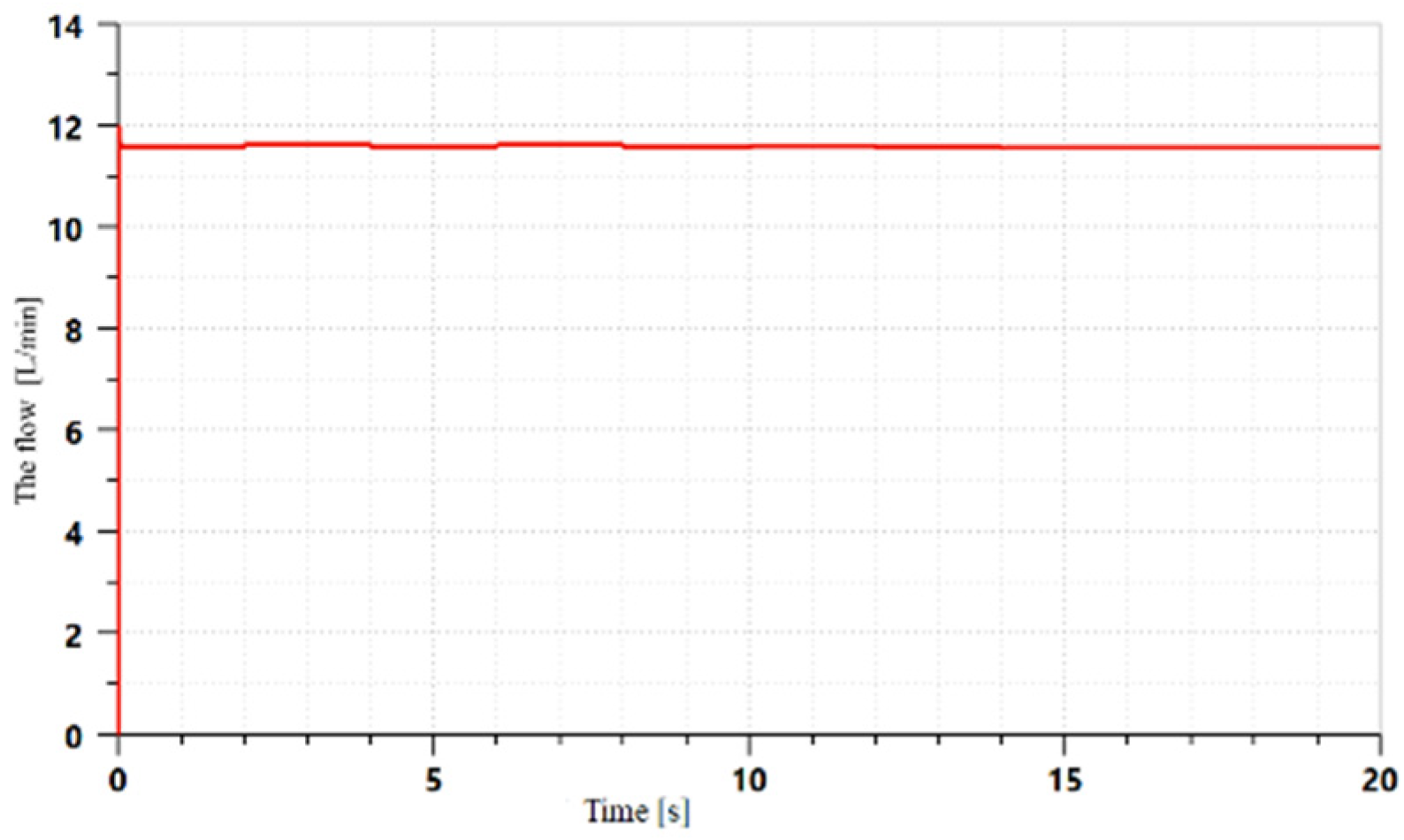
4.8. Influence of Viscous Damping Coefficient on Flow-Rate Fluctuation

The viscous damping coefficient between the valve sleeve and the pressure compensator is determined by the sealing ring compression, fit clearance, and other factors. The selection of the viscous damping coefficient plays a key role in the assembly of the governor valve. The simulation test results are shown in Figure 14, Figure 15, Figure 16, Figure 17, Figure 18 and Figure 19.
By comparing the flow rate corresponding to different viscous damping coefficients, it can be seen that the viscous damping coefficient did not affect the flow rate under stable conditions and its size had a great influence on the flow-rate fluctuation caused by pressure differences. The influence of the viscous damping coefficient on the flow rate was mainly reflected in the following aspects:
(1)
The viscous damping coefficient had no obvious effect on the flow-rate fluctuation when it increased or decreased by a small order of magnitude.
(2)
The initial wave peak of flow rate increased with the increase in the viscous damping coefficient.
(3)
After the flow and pressure difference fluctuate, the increase of viscous damping coefficient will lead to a long time to recover to the stable flow;
(4)
The flow-rate fluctuation increased with the increase in the viscous damping coefficient.
There is a big gap between the results here and those of the mathematical model because the viscous damping coefficient was mainly affected by the resistance and friction of the fluid. The motion speed of the spool was not high in the mediation process so the viscous friction coefficient did not play a large role.
Considering that the viscous friction coefficient increased to a certain extent, the movement speed of the spool slowed down, and the valve opening could not be adjusted in a short time so the flow rate fluctuated greatly. The movement of the spool was more stable and the adjustment speed was slow. When the coefficient of viscous friction was small, the response speed of the spool was faster and it was not easy to cause flow-rate fluctuations. From these two observations, the reliability of the simulation is higher. Therefore, the above mathematical modeling needs to be further analyzed and then modified in the selection of the viscous friction coefficient.

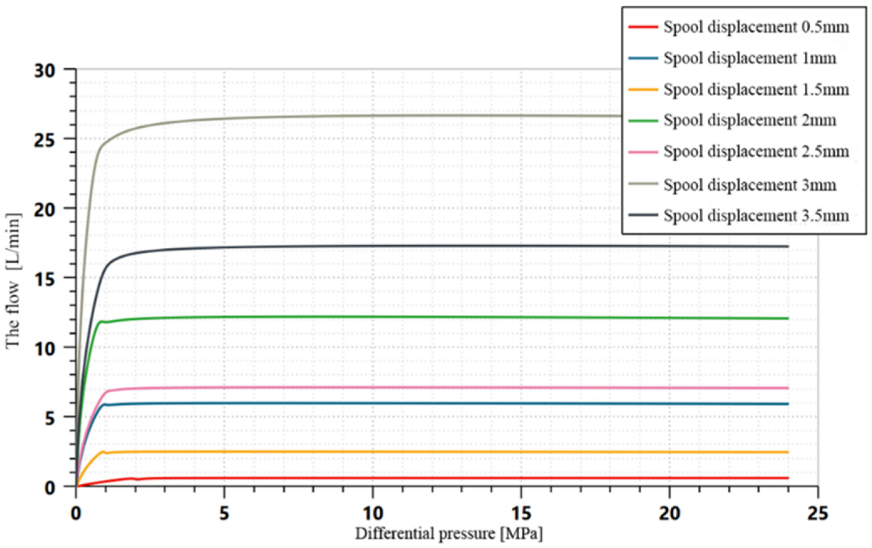
4.9. Flow-Rate Curve of Speed-Regulation Valve under Different Orifices

As an important functional index of the speed-regulation valve, it must be proven whether the speed-regulation valve meets the design requirements. According to the conclusion for the above simulation, the corresponding parameters were selected and entered into the program. When the pressure difference was set at 2 MPa, the valve core opening was adjusted and the simulation results are shown in Figure 20.
As can be seen in Figure 20, under different spool displacements, the flow rate within 0~1.5 MPa gradually increased with the increase in the pressure difference. After the pressure difference exceeded 1.5 MPa, the flow rate did not change with the increase in the pressure difference and was in a state of balance in line with the basic requirements of the speed-regulation valve.
After the study of the above parameters, the optimized spring stiffness, initial opening degree, spring preload force, viscous friction coefficient, and other parameters were determined and the curves were obtained after the optimization, as shown in Figure 21. The relevant parameters are shown in Table 3. Compared with the curve obtained from the data collected using the original speed-regulating valve parameters (Figure 22), it can be seen that the sensitivity of the optimized speed-regulating valve to sudden pressure differences was significantly reduced, which effectively reduced the flow-rate fluctuation and improved the recovery speed of the flow rate.

5. Conclusions

In this paper, the flow-rate fluctuation caused by a sudden change in the pressure difference of a speed-regulation valve with a pressure compensation function was analyzed and a mathematical model of the valve was established. Furthermore, the factors that can affect the flow-rate fluctuation were comprehensively analyzed and verified by an AMEsim simulation test. The results showed that the fluctuation of the flow rate of a speed-regulation valve with a pressure compensation function was only related to the step changes in the pressure difference, and that the continuous changes in the pressure difference did not cause a flow-rate overshoot. The influence of the pressure difference variables and viscous damping coefficient on the flow-rate fluctuation was analyzed under certain conditions.
The results showed that:
(1)
When the differential pressure increment was between 4 MPa and 10 MPa, the flow-rate fluctuation was the largest. When the differential pressure exceeded 10 MPa, the flow-rate fluctuation gradually became smaller.
(2)
The flow-rate fluctuation of the speed-regulating valve was proportional to the spring stiffness. The balance of the flow rate increased with the increase in the spring stiffness, and the spring stiffness was required to ensure the stability of the flow rate in the range of 3~12 N/mm.
(3)
The speed valve flow-rate peak increased with the increase in the preload, and the first flow-rate peak decreased with the increase in the preload; a reasonable preload should be guaranteed within 0.1~40 N.
(4)
The smaller the viscous damping coefficient of the governor valve, the more favorable it was for controlling the flow-rate fluctuation.
Optimizing the speed-control valve provides strong support for the smoothness control of a hydraulic actuator, which can effectively alleviate the problem of the speed of the actuator changing with the load.

Author Contributions

Conceptualization, Q.Z. and J.L.; methodology, Y.Y.; software, Q.Z.; validation, J.L., Y.Z. and C.P.; resources, J.L.; data curation, C.P.; writing-original draft preparation, Q.Z. and J.L.; writing-review and editing, Y.Z. and Y.Y.; funding acquisition, J.L. All authors have read and agreed to the published version of the manuscript.

Funding

This research was funded by the National Natural Science Foundation of China, grant number 51405113.

Acknowledgments

All authors in this article agree to this section and all the contents described herein.

Conflicts of Interest

The authors declare no conflict of interest.

References

  1. Jian, R.; Bin, M. 2D Digital Servo Valve. In China Mechanical Engineering Society Fluid Power Transmission and Control Branch Proceedings of the Sixth National Fluid Power Transmission and Control Conference; Machinery Industry: Lanzhou, China, 2010; pp. 84–105. [Google Scholar]
  2. Hai-i, Y.; Hong, J.; Ming-qian, G.; Qing-xuan, Z.; Jian-jun, Z.; Shuail, F. Mathematical Modeling and Simulation Analysis of Flow Control Valve. Chin. Hydraul. Pneum. 2019, 7, 27–32. [Google Scholar]
  3. Jialin, Z.; Wei, L.; Wenjian, X.; Jianwei, G. Research on Low Temperature Flow-rate Characteristic of New Pattern Proportional Speed Regulating Valve. Mach. Tool Hydraul. 2016, 44, 93–96. [Google Scholar]
  4. Liu, W.; Wei, J.; Hu, B. Analysis and Optimization of a Hydraulic-feedback Proportional Throttlecartridge Valve. In Proceedings of the 2013 2nd International Symposium on Quantum, Nano and Micro Technologies (ISQNM 2013), Singapore, 1–2 December 2013. [Google Scholar]
  5. Qing-tang, C.; Yi-jian, H.; Yi-ran, S. Fault diagnosis and analysis of speed-regulating valve based on AR trispectrum and its correlation dimension. J. Hefei Univ. Technol. Nat. Sci. 2014, 37, 1158–1163, 1181. [Google Scholar]
  6. Sen-lin, L.; Sheng-qing, Y.; Su-yan, W.; Bo, L. Exploring the Erosion Damage of Pollution Particles to the Throttle Valve Based on Fluent. Hydraul. Pneum. Seals 2022, 42, 30–36. [Google Scholar]
  7. Roger, F. Stability and Performance Analysis of a Metering Poppet Valve. Int. J. Fluid Power 2006, 7, 11–17. [Google Scholar]
  8. Zi-long, S.; Xiao-jun, Z.; Yi-wei, L.; Jie, Z. Flow field characteristics and optimization of non-full circumference ope n spool valve. J. Mech. Electr. Eng. 2022, 39, 317–323. [Google Scholar]
  9. Long, Q.; Xiaoqing, X.; Zheng, Y.; Xiaojun, Z. A New Kind of Pilot Controlled Proportional Direction Valve with Internal Flow Feedback. Chin. J. Mech. Eng. 2010, 23, 60–65. [Google Scholar]
  10. Wang-bo, Y.; Hong, J.; Xu-bo, Y.; Dong-ming, L. Influence of the Throttle Groove Nun aber on the Valve Spool Thermal Deformation. Hydraul. Pneum. Seals 2019, 39, 17–20. [Google Scholar]
  11. Jinsong, Z.; Chuanbi, Z.; Zining, Z.; Zhipeng, W.; Jing, Y. Static and Dynamic Characteristics of High speed On-off Digital Valves. China Mech. Eng. 2018, 29, 145–150, 157. [Google Scholar]
  12. Xingyu, J. Research on Proportional Flow Valve Controller and Dead-Time Compensation Strategy. Master’s Thesis, Taiyuan University of Technology, Taiyuan, China, 2021. [Google Scholar] [CrossRef]
  13. Haijuan, Z. Research on Proportional Flow Valve Characteristics Based on Digital Compensator. Master’s Thesis, Taiyuan University of Technology, Taiyuan, China, 2021. [Google Scholar] [CrossRef]
  14. Eriksson, B. Control Strategy for Energy Efficient Fluid Power Actuators: Tilizing Individual Metering. Licentiate Thesis, Linkoeping University, Linkoeping, Sweden, 2007. [Google Scholar]
  15. Shengmao, L. Research of Ultrahigh-Pressure and Large-Flow Cartridge Proportional Throttle. Bachelor’s Thesis, Zhejiang University, Hangzhou, China, 2019. [Google Scholar]
  16. Amirante, R.; Catalano, L.A.; Poloni, C.; Tamburrano, P. Fluid-dynamic design optimization of hydraulic proportional directional valves. Eng. Optim. 2014, 46, 1295–1314. [Google Scholar] [CrossRef]
  17. Meng, Q. The Design of the New Digital Direction Flow Valve and Feature Analysis. Master’s Thesis, Chongqing university, Chongqing, China, 2014. [Google Scholar]
  18. Zhijia, G.; Yanbin, L.; Wenbao, M. Numerical simulation of the flow characteristic of the giant magnetostrictive-driven flow valve. J. Chongqing Univ. Posts Telecommun. Nat. Sci. Ed. 2012, 24, 512–517. [Google Scholar]
  19. Guoping, L.; Wuxing, X.; Ronghua, H.; Dawei, Q. Mathematic Modelling and Simulation of a Two-way Electro-hydraulic Proportional Flow Valve. Mach. Tool Hydraul. 2013, 41, 179–181. [Google Scholar]
  20. Min, C.; Bing, X.; Jun-hui, Z.; Ru-qi, D. Valve-based compensation for controllability improvement of the energy-saving electrohydraulic flow matching system. J. Zhejiang Univ.-Sci. A Appl. Phys. Eng. 2017, 18, 430–442. [Google Scholar]
Figure 1. Flow-rate regulation structure diagram of speed-regulating valve. 1—Valve body; 2—pressure compensator; 3—spring; 4—valve sleeve; 5—throttle valve push rod; 6—throttle valve core.
Electronics 11 02580 g001
Figure 2. Flow chart of working principle of speed-regulating valve.
Electronics 11 02580 g002
Figure 3. AMEsim simulation model of speed-regulation valve.
Electronics 11 02580 g003
Figure 4. Change in flow rate and spool displacement when pressure difference changes from 2 MPa to 4 MPa. (a) Change in pressure difference of flow rate; (b) Change in pressure difference of spool displacement.
Electronics 11 02580 g004
Figure 5. Influence of different pressure changes on flow rate.
Electronics 11 02580 g005
Figure 6. Step change curve of flow rate with differential pressure.
Electronics 11 02580 g006
Figure 7. Influence of differential pressure increment on flow rate.
Electronics 11 02580 g007
Figure 8. Influence of different spring stiffnesses on flow-rate fluctuation.
Electronics 11 02580 g008
Figure 9. Flow-rate variation under spring stiffness from 0.1 N/mm to 3 N/mm.
Electronics 11 02580 g009
Figure 10. Flow rate changes when spring stiffness exceeded 12 N/mm.
Electronics 11 02580 g010
Figure 11. Flow-rate change in spring stiffness from 4 N/mm to 12 N/mm.
Electronics 11 02580 g011
Figure 12. Relationship between spring preload and flow-rate fluctuation.
Electronics 11 02580 g012
Figure 13. Influence of different initial openings on flow rate.
Electronics 11 02580 g013
Figure 14. Viscous damping coefficient of 20 N/(m·s).
Electronics 11 02580 g014
Figure 15. Viscous damping coefficient of 100 N/(m·s).
Electronics 11 02580 g015
Figure 16. Viscous damping coefficient of 1000 N/(m·s).
Electronics 11 02580 g016
Figure 17. Viscous damping coefficient of 2000 N/(m·s).
Electronics 11 02580 g017
Figure 18. Viscous damping coefficient of 4000 N/(m·s).
Electronics 11 02580 g018
Figure 19. Viscous damping coefficient of 20,000 N/(m·s).
Electronics 11 02580 g019
Figure 20. Differential pressure–flow rate characteristic curve.
Electronics 11 02580 g020
Figure 21. Traffic fluctuation after optimization.
Electronics 11 02580 g021
Figure 22. Flow-rate fluctuation before optimization.
Electronics 11 02580 g022
Table 1. Parameters of the governor valve.
ItemsValue
Inlet diameter of speed-regulation valve mm8
Inlet passage diameter mm8
Diameter at throttling port of valve sleeve mm7
Valve set inside diameter mm12
Diameter of valve sleeve pressure compensator mm4
Spring stiffness N/mm16.9
Stress area at oil inlet of pressure compensator mm2145.19
Diameter of oil inlet hole in pressure compensation chamber mm24
Speed-regulation valve outlet diameter mm8
Table 2. Corresponding relationship between flow-rate difference and differential pressure increment.
Differential increment
MPa
35811131618
Flow-rate difference value
L/min
2.683.113.362.972.872.231.66
Table 3. Selection of parameters related to speed-regulating valve after optimization.
The Parameter NameSpring
Stiffness
Spring PreloadInitial Opening of Pressure CompensatorViscous Damping Coefficient
Set parameters6 N/mm10 N2 mm1000 N/(m·s)
Publisher’s Note: MDPI stays neutral with regard to jurisdictional claims in published maps and institutional affiliations.

