Article

Electromagnetic Characteristics Analysis of Quadrupole Compound Orbital Electromagnetic Launcher with Different Configurations

Air and Missile Defense College, Air Force Engineering University, Xi’an 710051, China
*
Author to whom correspondence should be addressed.
Electronics 2022, 11(17), 2650; https://doi.org/10.3390/electronics11172650
Submission received: 18 July 2022 / Revised: 20 August 2022 / Accepted: 23 August 2022 / Published: 24 August 2022

Abstract

:
During the operation of the Quadrupole Compound Orbital electromagnetic launcher, the current is easy to gather in the armature and the rail contact surface. Serious turn and arc ablation can occur, causing damage to the rail and the armature and affecting the life of the launcher. To better solve the thermal ablation problem of the armature and the rail, three different configurations of the rail and the armature are established, and the current density, magnetic field distribution and electromagnetic force of the rail and the armature are compared and analyzed using the finite element method, and the effect of concave and convex values of the armature rail on current distribution and electromagnetic force is discussed. The results show that the planar armature can effectively reduce the maximum current density and mitigate thermal damage. The concave elliptical rail produces the largest electromagnetic thrust and the smallest radial electromagnetic force, and the armature is more stable during firing. The maximum current density and magnetic field strength are negatively correlated with the concave and convex values; the electromagnetic thrust applied to the concave elliptical armature is negatively correlated with the concave value, while the electromagnetic force applied to the convex elliptical armature is positively correlated with the convex value.

1. Introduction

Electromagnetic launch is a new type of launch method that uses the strong electromagnetic thrust generated by the interaction of electric current and a magnetic field to achieve acceleration. Compared with a traditional launch, electromagnetic launch has many advantages such as fast launch speed, high efficiency, high safety and low cost [1,2,3]. With the continuous research, electromagnetic launch has developed from the initial double-rail launch to a quadruple-rail launch. Compared with the ordinary double-rail electromagnetic launcher, the quadrupole orbital electromagnetic launcher is not only more stable in structure with greater launch effectiveness, but also can provide an ideal electromagnetic shielding area for the munition. The quadrupole composite rail electromagnetic launcher can effectively improve the current distribution on the contact surface of the armature and the rail and provide a larger magnetic field shielding range compared with the ordinary quadrupole orbital electromagnetic launcher [4,5]. The research on the electromagnetic characteristics of electromagnetic launchers is the basis for other research. Scholars at home and abroad have conducted a lot of research work on the electric field, magnetic field characteristics and structural design of electromagnetic launchers.
Cobum et al. [6] experimentally measured the magnetic and electric fields near the investigation point of the device. Wang et al. [7] used the self-developed Railgun3D program to simulate the electromagnetic field evolution process of the electromagnetic launcher based on the moving window method. Zhang et al. [8] analyzed the current and magnetic field distribution of orbital launchers at different calibers to provide a basis for the design of large caliber electromagnetic orbital launchers. Ruan et al. [9] and others summarized the current status of research on the current distribution characteristics of electromagnetic rail guns at home and abroad more completely and proposed measures to optimize the current distribution. Liu et al. [10] designed a new four-rail electromagnetic launcher with a three-leaf petal-shaped armature to obtain greater electromagnetic force. Li et al. [11,12] studied four-rail electromagnetic launchers with different armature configurations and derived their current distribution and hydrostatic characteristics. From the present research results, the study of electromagnetic characteristics of electromagnetic launchers concentrates on the common rail-to-model, while the study of the effect of the structure of complex composite multi-rail electromagnetic launchers on electromagnetic characteristics is rare.
Based on the above analysis, this paper designs three different configurations of rail and armature structures based on the four-pole composite rail electromagnetic launcher and simulates and compares the electromagnetic characteristics to investigate the distribution law of current and the relationship between electromagnetic thrust and structure, which provides some reference for the structural design of the launcher.

2. Physical Model and Simulation Conditions

2.1. Physical Model

The four-pole composite rail electromagnetic launcher model used in this paper is shown in Figure 1, where the four-pole composite rail adds another layer of steel rail to the inner layer of the conventional rail. The four rails are distributed in a uniform circular array with the armature as the center, and the pulse current flows in from the two opposite copper rails, flows through the armature and then flows out from the remaining two rails. The copper-based rails are used to generate and conduct the current and provide the magnetic field, and the steel rails are used to carry the armature [5,13]. Due to the structural symmetry of the rail and armature, the magnetic fields generated by the current at the center of the armature will cancel each other, thus forming a magnetic shielding area. Considering the need for electromagnetic shielding of the armature-carrying smart munitions, the armature adopts a hollow design as shown in Figure 1. The four-pole composite rail electromagnetic launcher has an aperture of 80   mm × 80   mm , a copper rail length of 1000   mm , a height of 40   mm , and a width of 15   mm . The length and height of the steel rail are consistent with the copper rail, which are 1000   mm and 40   mm , respectively, and the width is 5   mm .
The quadrupole composite rail adds another layer of steel rail to the inner layer of the traditional rail. The entire electromagnetic launcher only uses one power supply device, the adjacent rails pass in the opposite direction of current, and the opposite rails pass in the same direction of current. The copper-based rail is used to generate, conduct current and provide the magnetic field, and the steel rail is used to carry the armature.
Considering the flow-through capacity and mechanical strength of the armature and rail, the caliber of the four-pole composite rail electromagnetic launcher is 80   mm × 80   mm , the length of the copper rail is 1000   mm , the height is 40   mm , and the width is 15   mm . The length and height of the steel rail are consistent with those of the copper rail, which are 1000   mm and 40   mm , respectively, and the width is 5   mm . The rail and armature material characteristics are shown in Table 1.
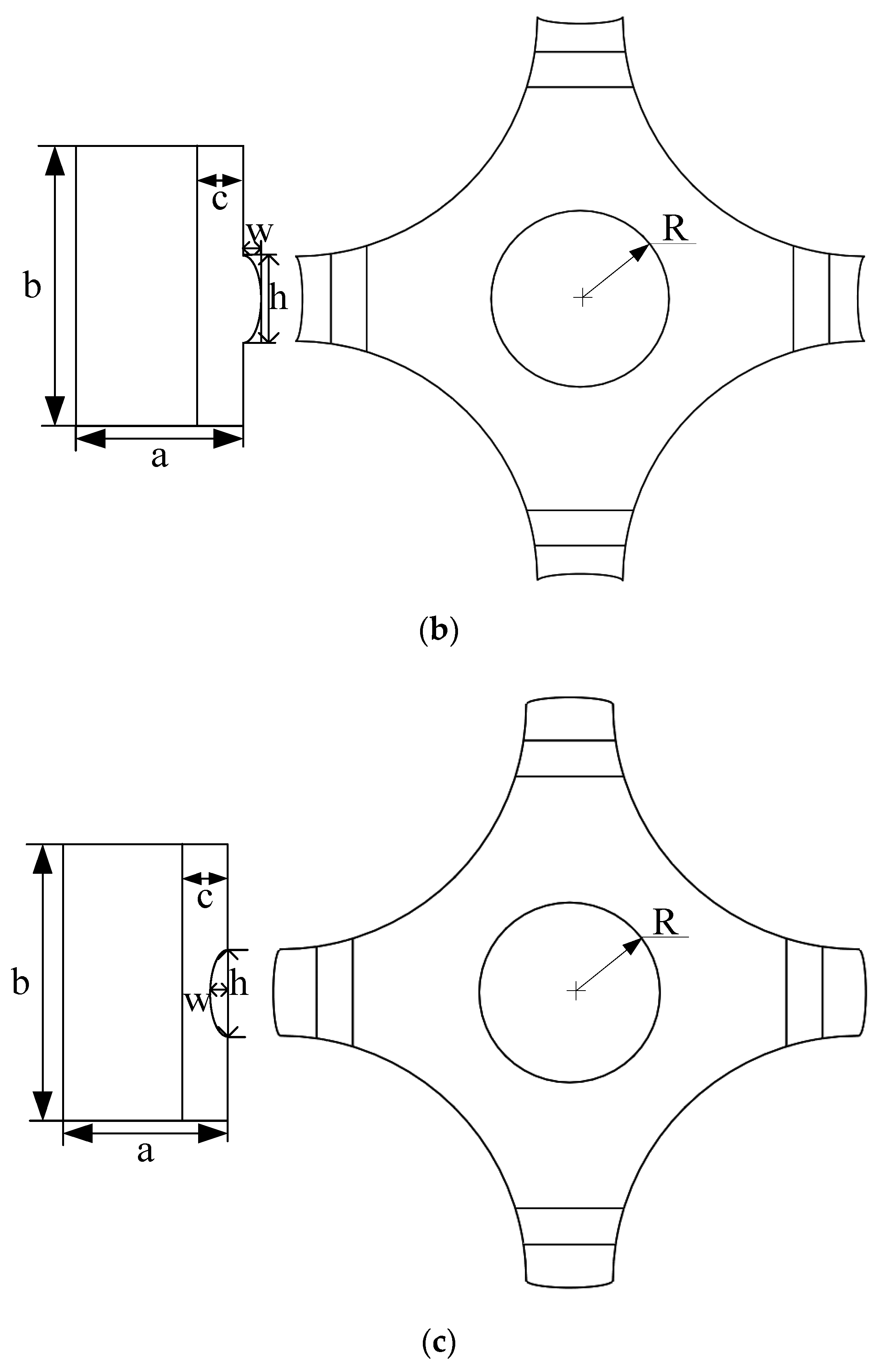
To investigate the influence of the shape of the contact surface of the armature and rail on the electromagnetic characteristics of the launcher, three different configurations of rail and armature structures are designed based on the four-pole composite rail electromagnetic launcher, which are planar rail-plane armature, convex elliptical rail-concave elliptical armature and concave elliptical rail-convex elliptical armature. The three launcher configurations are shown in Figure 2. The geometric model parameters are shown in Table 2.

2.2. Simulation Conditions

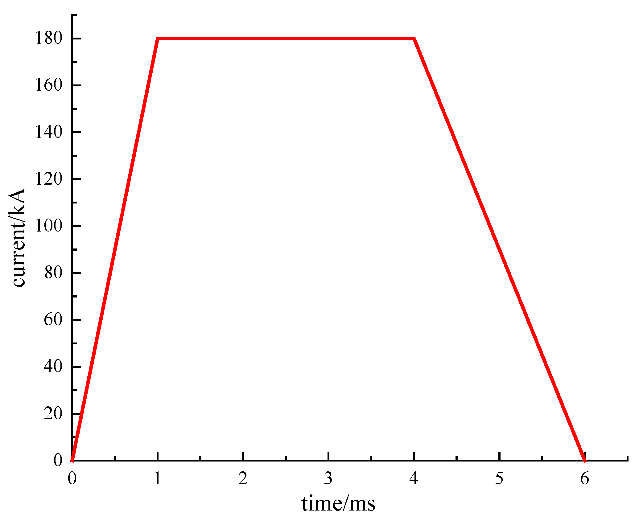
The electromagnetic rail launcher is a complex transient process, and the transient current should be used for simulation. Through the waveform research, it is found that the direct application of the pulsed strong current on the rail will generate a relatively strong electromagnetic force, and the trapezoidal current waveform has the best effect. Therefore, the trapezoidal current excitation shown in Figure 3 is used in this paper. The current conduction time is 6 ms, the amplitude is 180 kA, the rising edge time is 1 ms, the current peak duration is 3 ms, and the falling edge time is 2 ms. Since the change of the current in a short time will lead to the generation of the induced current, it is necessary to set the “Eddy Effect” in the simulation analysis to consider the skin effect of the current. Set the vacuum area for the solution to 300%.

3. Simulation Analysis

3.1. Analysis of Electromagnetic Characteristics of Different Configurations

During the operation of the four-pole composite orbital electromagnetic launcher, the contact condition of the armature and rail will have complicated changes, and the current will easily gather on the contact surface of the armature and rail, which will cause severe turning and arc ablation, damaging the rails and armatures and affecting the service life of the launcher. The current distribution, magnetic field strength and force of different configurations of armature and rail are analyzed under the same excitation load.
Transient simulations are performed for different configurations of armature rails to obtain the current and magnetic field distributions of the armature rails at different moments. The current and magnetic field at 4 ms are selected for analysis, and Figure 4 shows the current density distribution on the contact surface of the three different configurations of the armature.
From Figure 4, it can be seen that the current distributions on the contact surfaces of the three armature configurations are quite different.
From the location of distribution, the current distribution on the contact surface is extremely uneven due to the skin effect of current. The current is mainly distributed on the edge of the contact surface, and a more serious current concentration occurs at the sharp corners of the contact surface, especially at the bottom of the armature, which is also related to the shortest path of the current [14]. The current on the contact surface of the planar armature is mainly distributed on the armature tail and armature arm head, while there is almost no distribution in the middle region of the contact surface. The current on the contact surface of the convex elliptical armature is mainly distributed on the two edges. The current on the contact surface of the concave elliptical armature is concentrated on the two edges, with less current distribution in the middle region.
The distribution of the launcher current affects the distribution of the magnetic field in space, and the more concentrated the current, the stronger the magnetic field excited in space. The excited magnetic field interacts with the armature current to produce electromagnetic thrust to propel the armature forward. The magnetic field at the front and rear end of the armature is analyzed to investigate the magnetic field distribution pattern near the armature. This is shown in Figure 5.
As can be seen from the figure, the magnetic field intensity distribution at the end face of the armature of different configurations is the same and has a good symmetry of distribution. The magnetic fields in the middle of the armature cancel each other, and a zero magnetic field area appears, which can provide a good electromagnetic environment. The magnetic field on the rail is stronger and concentrated at the armature and rail contact due to the magnetic permeability of the rail. The magnetic field at the rear end of the armature is similar to the magnetic field distribution at the front end of the armature. The convex (concave) elliptical armatures all show the maximum magnetic field strength at the armature and rail contact position. Comparing the magnetic field strengths of the three armatures, it is found that the maximum magnetic field strengths at the front face of the planar armature, concave elliptical armature and convex elliptical armature are 7.19   T , 7.74   T and 7.45   T , respectively. It can be seen that the maximum magnetic field strength at the front face of the concave-elliptical armature is larger, which is consistent with the aforementioned current analysis.
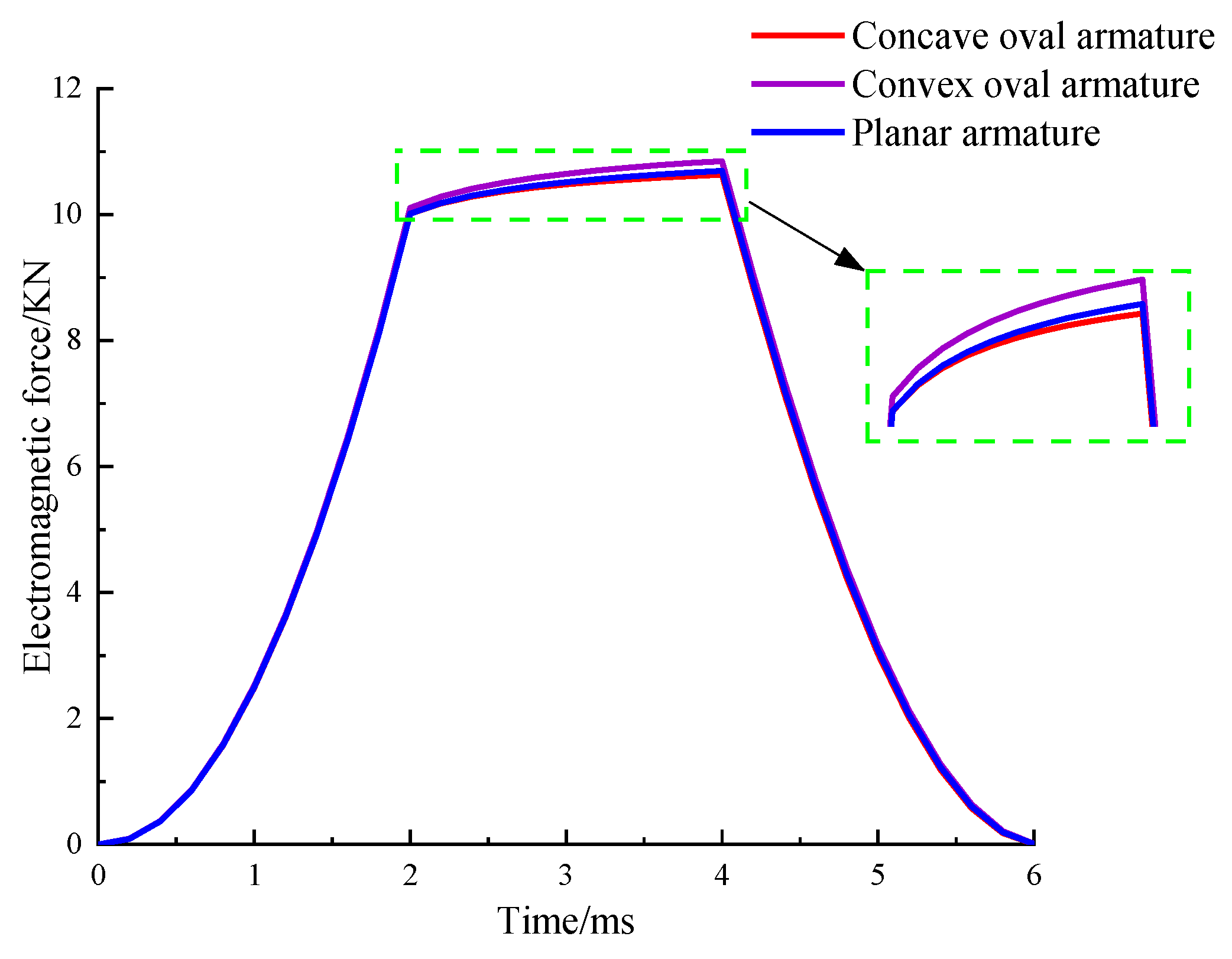
When a four-pole composite orbital electromagnetic launcher is in operation, one part of the electromagnetic force is used to drive the armature at high speed, called electromagnetic thrust; the other part is used to provide good electromagnetic contact between the armature and the rail. The electromagnetic force plays an important role in both armature motion and contact, so it is necessary to simulate and analyze the electromagnetic force. Figure 6 shows the variation of electromagnetic thrust with time for three configurations of armatures.
The analysis shows that the change trend of the electromagnetic thrust on the three configuration armatures with time is consistent. At 0~2 ms, the thrust increases rapidly, and the growth rate is relatively large. After reaching 2 ms, the thrust maintains a high level and increases slightly. After 4 ms, the thrust decreases and quickly drops to zero. This is related to the incoming current waveform. In practical launch applications, in order to maximize the use of energy and ensure that the armature has a high exit velocity, the load is usually launched before the thrust drops. Comparing the curves of the three, it can be seen that the electromagnetic thrust of the concave elliptical armature is the smallest, which is only 10.63 N. The electromagnetic thrust of the planar armature is the second, which is 10.69 N. The electromagnetic thrust of the convex elliptical armature is the largest, which is 10.85 N. This is because the cross-sectional area of the concave elliptical rail is smaller, the current density is larger when the same current is passed through, and the magnetic field excited in space is stronger, thereby generating a larger electromagnetic thrust.
Table 3 shows the armature force of the three configuration armatures at 4 ms. In Table 3, F A represents the total electromagnetic force of the armature, and F x , F y and F z represent the components of the electromagnetic force on the armature in the X, Y and Z directions, respectively.
It can be seen from the above table that under the condition of the same current, the configuration of the rail is different, and the current density and the current distribution are different, resulting in different forces in different directions. Comparing the force of the armature in the X and Y directions, it can be seen that the component forces of the convex elliptical armature in the X and Y directions are small, indicating that the armature has better stability during the launch process and high energy utilization, and the planar armature is subjected to large force, which is likely to cause uneven force on the armature, resulting in armature deformation or even derailment.

3.2. Influence of Concave (Convex) Value on Electromagnetic Properties

It can be seen from the above analysis that the electromagnetic characteristics and forces of the three armature and rail configurations are quite different, which are closely related to their structures, and the concave (convex) value is an important factor. This section mainly discusses the influence of concave (convex) value changes on relevant characteristics [15]. Set the concave (convex) values to 0 mm, 1 mm, 2 mm and 3 mm, respectively.
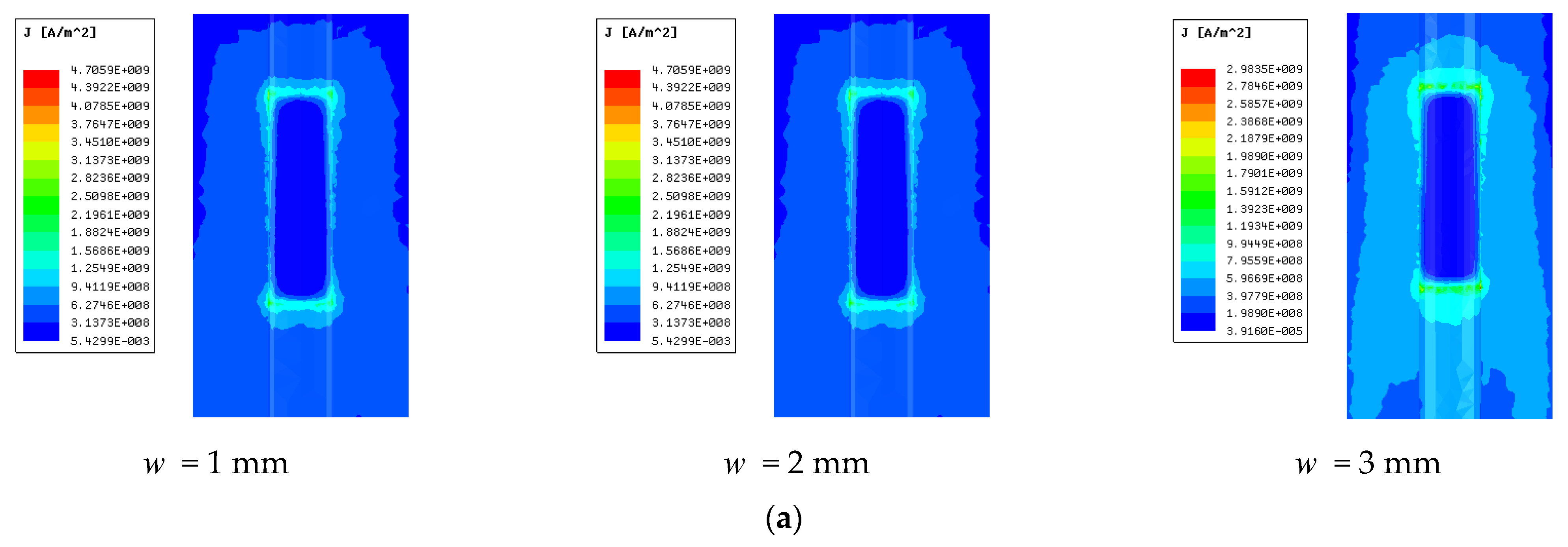
The contact of the armature and the rail is prone to current concentration. The rail is simulated and analyzed when the w is 1, 2 and 3 mm, respectively. The distribution of the rail current at 4 ms is shown in Figure 7.
It can be seen from Figure 7 that the maximum current density of both rails decreases with the increase of w , and when w is 1 mm, 2 mm and 3 mm, respectively, the maximum current density of the convex elliptical rail is 4.71 × 10 9   A / m 2 , 3.73 × 10 9   A / m 2 and 2.98 × 10 9   A / m 2 , respectively, and the maximum current density at w = 3   mm of the convex elliptical rail decreases by 36.73 % when compared with w = 1   mm . The maximum current density of the concave elliptical rail is 4.57 × 10 9   A / m 2 , 3.56 × 10 9   A / m 2 and 2.81 × 10 9   A / m 2 , respectively. The maximum current density at w = 3   mm of the concave elliptical rail decreases by 38.51 % when compared with w = 1   mm . In comparison, the decrease of the concave elliptical rail is larger. For the concave (convex) elliptical rail, the increase of w means that the contact area between armature and rail increases, and the current has more circulation paths, which can alleviate the current concentration on the contact surface of the armature rail to some extent. Observing the images, it can be seen that the currents of the convex elliptical rail are mainly distributed on the raised elliptical rail surface with less distribution on both sides, while the concave elliptical rail currents are more distributed in the area on both sides of the contact and less current distribution in the concave part.
The maximum current density on the contact surface of the armature of different configurations varies with w as shown in Table 4.
As can be seen from the table, the maximum current density on the armature contact surface also shows a decreasing trend with the increase of w . The maximum current density on the contact surface of the concave elliptical armature is the largest. When w is 1 mm, 2 mm and 3 mm, respectively, the maximum current density of the concave elliptical armature is 2.314 × 10 10   A / m 2 , 1.928 × 10 10   A / m 2 and 1.635 × 10 10   A / m 2 , which decreases by 29.34 % ; the maximum current density of the convex elliptical armature is 8.18 × 10 9   A / m 2 , 3.56 × 10 9   A / m 2 and 2.81 × 10 9   A / m 2 , which decreases by 65.65 % . When the concavity of the interface changes, the current flowing from the contact surface of the armature and rail is certain. When the concavity of the interface increases, the contact area increases, while the current density on the armature arm along the direction of armature movement does not change, so the contact electromagnetic force generated is certain, and the contact pressure decreases. The contact resistance of the armature and the rail is calculated as follows [16]:
ρ c o n l c o n = ρ a v e r C H s o f t P m
where ρ c o n denotes the contact resistivity of the contact surface, l c o n denotes the thickness of the contact surface, ρ a v e r indicates the average resistivity of the two contact bodies, both C and m are constants, H s o f t is the hardness of the softer contact body, and P indicates contact pressure.
According to the contact resistance calculation formula, when P decreases, the contact resistance on the contact surface of the armature and rail will increase, so the current density will also decrease. The concave elliptical armature corresponds to a convex elliptical rail and the convex elliptical armature corresponds to a concave elliptical rail. The cross-sectional area of the rail is larger for the convex elliptical rail, so the cross-sectional area of the convex elliptical rail changes less compared to its initial area when the w value is changed, while the concave elliptical rail is the opposite, so the maximum current density reduction of the concave elliptical armature is smaller than that of the convex elliptical armature with increasing w value.
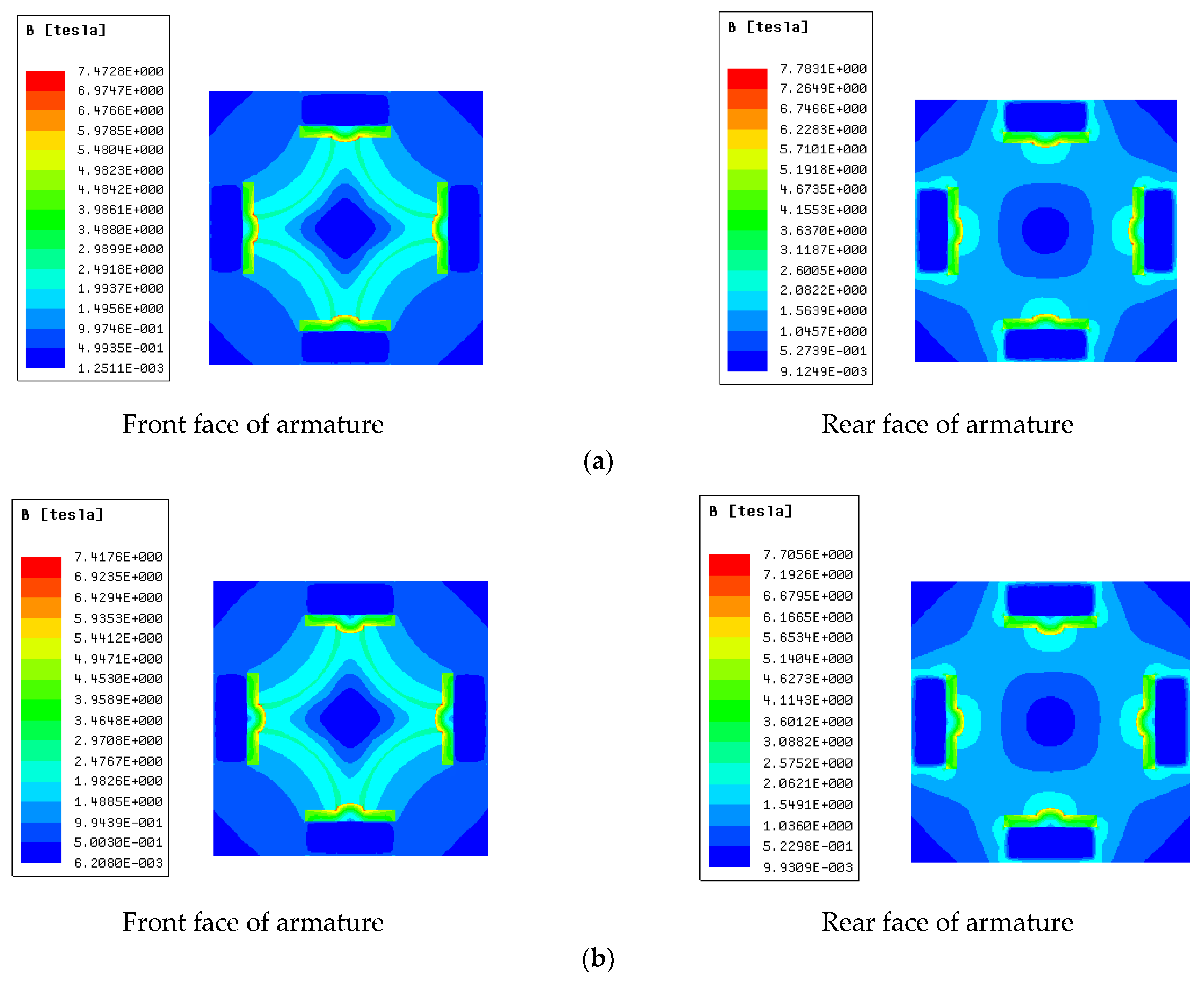
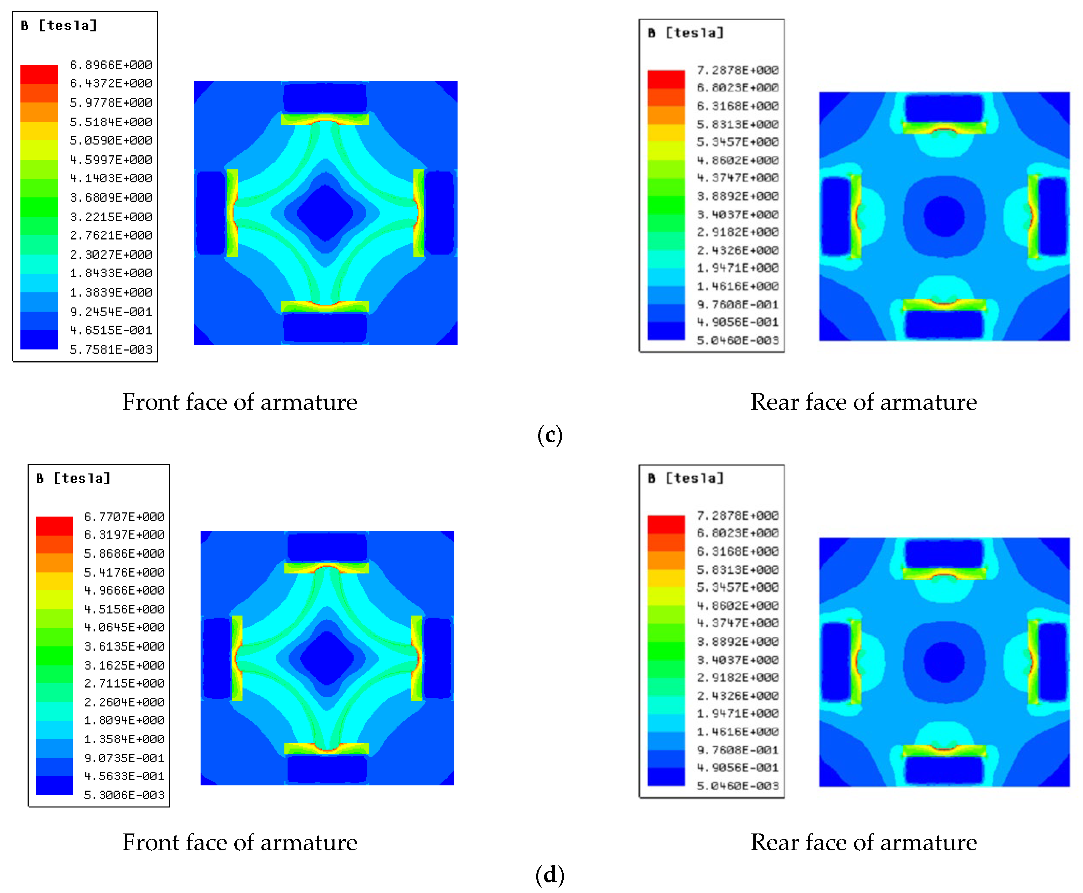
Figure 8 shows the magnetic field distribution on the front and rear end surfaces of the armature with different concave (convex) values.
It can be seen from the figure that the magnetic field at the front and rear surfaces of the armature decreases to a certain extent with the increase of w . Comparing the magnetic field strengths of the armature end faces of the two configurations, it is found that the magnetic field strength on the front and rear faces of the concave elliptical armature is greater than that of the convex elliptical armature. Comparing the magnetic field strengths of the front and rear faces of the armature with the same configuration, the rear face of the armature is larger than the front face of the armature. This is closely related to the distribution of the current. When the w is 1 mm, 2 mm, and 3 mm, respectively, the maximum magnetic field strength at the rear end of the concave elliptical armature is 8.10   T , 7.78   T , and 7.71   T , decreasing by 4.81 % . The maximum magnetic field strengths on the front face are 7.74   T , 7.47   T and 7.41   T , respectively, decreasing by 4.26 % . The maximum magnetic field strengths at the rear end of the convex elliptical armature are 7.42   T , 7.28   T and 7.08   T ,respectively, which is reduced by 4.58 % . The maximum magnetic field strengths on the front face are 7.45   T , 6.89   T and 6.77   T , respectively, decreasing by 9.13 % .
The variation of electromagnetic thrust on the armature with time for different values of concavity is shown in Table 5.
It can be seen from Table 4 that the electromagnetic thrust on the concave elliptical armature is negatively correlated with w , while the concave elliptical armature is positively correlated. It can be seen that the change of w has different effects on the maximum electromagnetic thrust on the armature with different configurations. This is because the convex elliptical rail corresponding to the concave elliptical armature w increases. The cross-sectional area of the rail increases, and the average current density decreases when the same current is applied, making the magnetic field excited by the rail in space weaker, and the electromagnetic thrust decreases [17]. The positive correlation between the convex elliptical armature and the positive correlation is due to the increase of w , which increases the orbital current density on one hand, and the stronger concentration of current at the bottom of the armature, on the other hand. The increase of w means that the launcher aperture is increased to a certain extent, and the inductance gradient of the launcher increases, while the electromagnetic thrust rises. Therefore, different configurations of rails can provide different electromagnetic thrust, and different launch requirements can be met by designing a reasonable armature and rail structure.

4. Conclusions

In this paper, three different configurations of armature and rail structures are designed, and the simulation compares the current density, magnetic field strength distribution and electromagnetic thrust of different configurations of armature and rail. The effect of concave (convex) values of different configurations of armature and rail on the electromagnetic characteristics of the launcher is also analyzed, and the simulation results show that:
(1)
On the contact surface of the armature and the rail, the maximum current density of concave elliptical armature is 6.4 times and 2.8 times that of the flat armature and the convex elliptical armature, respectively, and the maximum current density of the flat armature is the smallest, which shows that the flat armature can effectively reduce the maximum current density and mitigate thermal damage.
(2)
Among the three configurations, the maximum magnetic field strength at the front and rear end surfaces of the concave elliptical armature is larger, but the concave elliptical rail produces the largest electromagnetic thrust and the smallest radial electromagnetic force. Moreover, the armature is more stable in the firing process with the highest energy utilization.
(3)
The maximum current density on the contact surface of the armature and the rail and the magnetic field strength at the front and rear end surfaces of the armature are negatively correlated with w. As w changes from 1 to 3, the maximum current density of the convex elliptical rail decreases on the contact surface of the armature and the rail, and the concave elliptical rail decreases. The electromagnetic thrust on the concave elliptical armature is negatively related to w, while the electromagnetic force on the convex elliptical armature is positively related to w.
When designing the four-pole composite orbital electromagnetic launcher, the stability of the armature movement in the bore and the energy utilization efficiency are considered comprehensively, and the convex elliptical armature should be selected preferentially considering the mitigation of the current concentration problem of the electromagnetic launcher. The research in this paper provides a reference for the structural design of the four-pole composite orbital electromagnetic launcher. In future work, we will continue to study the relevant characteristics of the temperature and structural fields in depth and optimize the design of the launcher under the constraints of high temperature failure threshold and high magnetic field failure threshold.

Author Contributions

Conceptualization, P.Z.; Data curation, P.Z.; Formal analysis, P.Z.; Investigation, T.L.; Methodology, T.S.; Project administration, T.S.; Resources, P.Z.; Software, P.Z.; Supervision, T.S.; Validation, T.L.; Visualization, T.S. and T.L.; Writing–original draft, P.Z.; Writing–review & editing, T.S. All authors have read and agreed to the published version of the manuscript.

Funding

This research received no external funding.

Institutional Review Board Statement

Not applicable.

Informed Consent Statement

Not applicable.

Data Availability Statement

The data presented in this study are available on request from the corresponding author.

Acknowledgments

The authors would like to thank their teachers, friends and other colleagues for their discussions on simulation and comments on this paper.

Conflicts of Interest

The authors declare no conflict of interest.

References

  1. Lu, J.Y.; Feng, J.H.; Li, K.; Li, X.P. Review of research on ultra-high-speed guided projectiles. J. Harbin Eng. Univ. 2021, 4, 1–12. [Google Scholar]
  2. Wang, Y. On electromagnetic launcher to open the era of electromagnetic weapons. Electr. Technol. 2010, (S1), 1–4. [Google Scholar]
  3. Ma, W.M.; Lu, J.Y.; Li, X.P. Electromagnetically launched hypervelocity integrated projectile. J. Natl. Univ. Def. Technol. 2019, 41, 1–10. [Google Scholar]
  4. Li, T.D.; Feng, G.; Liu, S.W. Analysis of electromagnetic characteristics of the proposed composite four-rail electromagnetic launcher. Sci. Eng. Compos. Mater. 2022, 29, 113–125. [Google Scholar]
  5. Li, T.D.; Feng, G.; Liu, S.W.; Shi, J.M.; Fan, C.L. Simulation and Analysis of Electromagnetic Characteristics of Copper-based Composite Quadrupole Rail. Syst. Eng. Electron. Technol. 2021, 43, 3054–3063. [Google Scholar]
  6. Coburn, W.O.; Le, C.; DeTroye, D.J.; Blair, G.E.; Williams, W. Electromagnetic field measurements near a railgun. IEEE Trans. Magn. 1995, 31, 698–703. [Google Scholar] [CrossRef]
  7. Wang, G.H.; Xie, L.; Zhao, H.L.; Kan, M.X.; Xiao, B.; He, Y.; Song, S.Y. Simulation analysis of electromagnetic field evolution during launch of tandem-enhanced railgun based on moving window. Explos. Shock. 2021, 41, 111–118. [Google Scholar]
  8. Zhang, H.H.; Li, S.; Gao, X.; Lu, T.; Liu, F. Distribution Characteristics of Electromagnetic Field and Temperature Field of Different Caliber Electromagnetic Railguns. IEEE Trans. Plasma Sci. 2020, 48, 4342–4349. [Google Scholar] [CrossRef]
  9. Ruan, J.H.; Chen, L.X.; Xia, S.G.; Wang, Z.J.; Li, L.D. Review of current distribution characteristics of electromagnetic railguns. J. Electrotech. Technol. 2020, 35, 4423–4431. [Google Scholar]
  10. Liu, M.; Tao, S.; Xue, X.P. New Quadrupole Orbital Electromagnetic Launcher. Firepower Command Control 2019, 44, 23–27. [Google Scholar]
  11. Li, T.D.; Feng, G.; Liu, S.W.; Ren, S.D.; Fan, C.L. Static analysis of armature and rail with different configurations of four-rail electromagnetic launcher. J. Ballist. 2021, 33, 90–96. [Google Scholar]
  12. Li, T.D.; Feng, G.; Liu, S.W.; Ren, S.D.; Fan, C.L. Influence of orbital configuration of four-rail electromagnetic launcher on current distribution. Weapon Mater. Sci. Eng. 2021, 44, 5–11. [Google Scholar]
  13. Xie, H.; Yang, H.; Yu, J.; Gao, M.Y.; Shou, J.D.; Fang, Y.T.; Liu, J.B.; Wang, H.T. Research progress on advanced rail materials for electromagnetic railgun technology. Def. Technol. 2021, 17, 429–439. [Google Scholar] [CrossRef]
  14. Mao, B.Q.; Zhang, T.Y.; Bai, X.H.; Zhu, R. Design of anti-ablation armature structure for electromagnetic rail gun. J. Ordnance Equip. Eng. 2020, 41, 67–71. [Google Scholar]
  15. Praneeth, S.R.N.; Singh, B.; Khatait, J.P. Study on effect of rail filet radius in electromagnetic railgun. IEEE Trans. Plasma Sci. 2021, 49, 2997–3002. [Google Scholar] [CrossRef]
  16. Hsieh, K.T.; Satapathy, S.; Hsieh, M.T. Effects of pressure-dependent contact resistivity on contact interfacial conditions. IEEE Trans. Magn. 2009, 45, 313–318. [Google Scholar] [CrossRef]
  17. Lydia, J.; Karpagam, R.; Murugan, R. A Novel Technique for Dynamic Analysis of an Electromagnetic Rail Launcher using FEM Coupled with Simplorer. Appl. Comput. Electromagn. Soc. J. (ACES) 2022, 37, 229–237. [Google Scholar] [CrossRef]
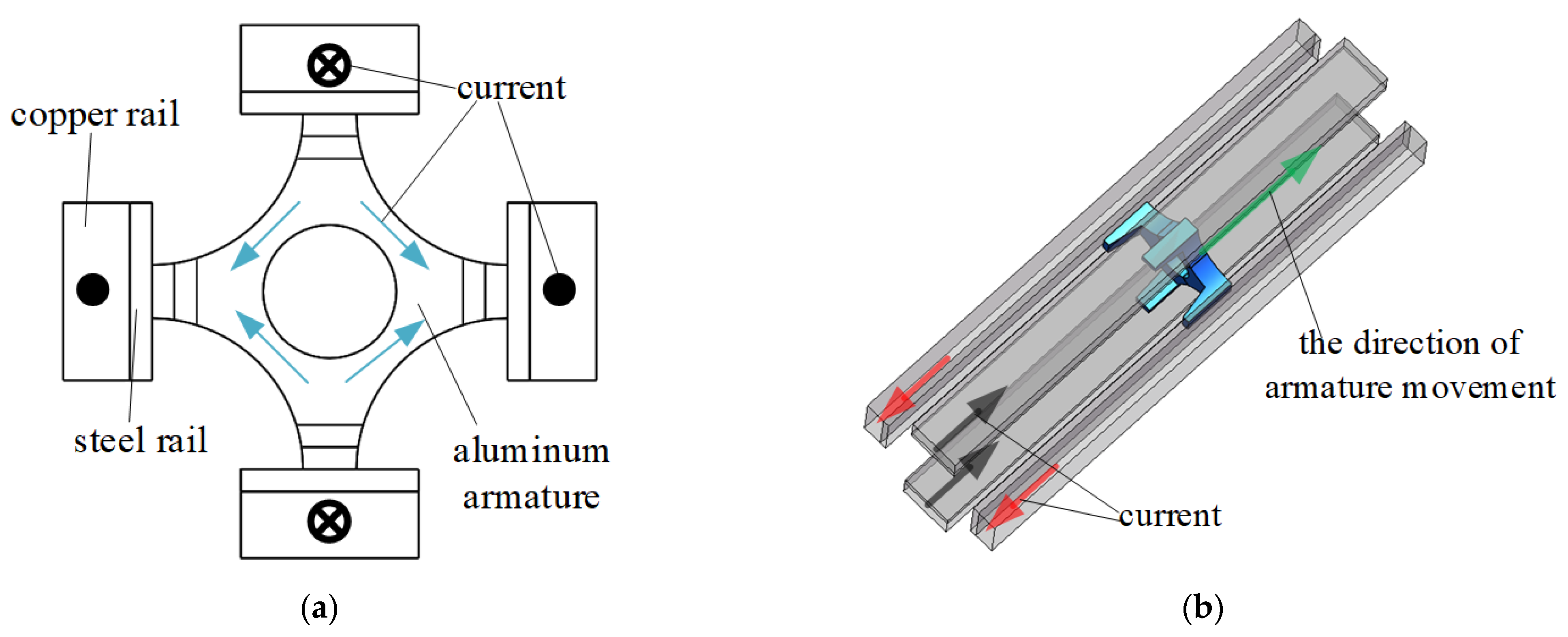
Figure 1. Model of quadrupole compound orbital electromagnetic launcher: (a) top view of the model (b) 3-dimensional model.
Electronics 11 02650 g001
Figure 2. Rail-armature models of different configurations: (a) flat type rail—flat type armature; (b) convex elliptic rail—concave elliptic armature; (c) concave elliptical rail—convex elliptical armature.
Electronics 11 02650 g002aElectronics 11 02650 g002b
Figure 3. Transient simulation current diagram.
Electronics 11 02650 g003
Figure 4. Current density distribution on the contact surface of three armatures: (a) planar type armature; (b) convex elliptical armature; (c) concave elliptical armature.
Electronics 11 02650 g004
Figure 5. Magnetic field distribution of the three armature end surfaces: (a) flat type armature front face; (b) flat type armature rear end face; (c) front face of concave elliptical armature; (d) rear face of concave elliptical armature; (e) front face of convex elliptical armature; (f) rear face of convex elliptical armature.
Electronics 11 02650 g005
Figure 6. Electromagnetic thrust on the armature of the three configurations.
Electronics 11 02650 g006
Figure 7. Distribution of orbital current density with different concave (convex) values: (a) convex elliptical rail; (b) concave oval rail.
Electronics 11 02650 g007aElectronics 11 02650 g007b
Figure 8. Magnetic field distribution on the end face of armature with different concave (convex) values: (a) concave oval armature (a = 2 mm); (b) concave oval armature (a = 3 mm); (c) convex oval armature (a = 2 mm); (d) Convex oval armature (a = 3 mm).
Electronics 11 02650 g008aElectronics 11 02650 g008b
Table 1. Electromagnetic launcher material properties.
Material Density / ( kg m 3 ) Conductivity / ( S m 1 ) Relative Permeability/−
Copper railcopper 8.66 × 10 3 5.80 × 10 7 0.999991
Steel railsteel7800 2.0 × 10 6 200
Armaturealuminum 2.70 × 10 3 3.76 × 10 7 1.000021
Table 2. Model geometric parameters.
Parameters a b c h R w
Value/mm 20 40 5 20 12.5 1
Table 3. Electromagnetic force on armatures of three configurations.
Armature F x / KN F y / KN F z / KN F A / KN
Convex elliptical type0.0160.02410.8510.85
Planar type0.1460.08110.6910.69
Concave oval type0.0230.03610.6310.63
Table 4. Maximum current density of armature contact surface at different concave (convex) values.
ArmatureConcave Oval TypeConvex Elliptical TypePlanar Type
Concave (Convex) Value/mm1231230
Maximum   current   density / ( × 10 9   A / m 2 ) 23.1419.2816.358.186.905.173.62
Table 5. Maximum electromagnetic thrust for different configurations of armatures.
w / mm Maximum Electromagnetic Thrust/KN
Concave Elliptical Type ArmatureConvex Elliptical
Type Armature
Planar
Type Armature
110.6310.8510.69
210.3710.96
39.9311.06
Publisher’s Note: MDPI stays neutral with regard to jurisdictional claims in published maps and institutional affiliations.