Article

Development of an Automatic Water Exchange System for Smart Freshwater Aquarium

by
Dorota Stachowiak
* and
Pawel Hemmerling
Faculty of Control, Robotics and Electrical Engineering, Poznań University of Technology, Piotrowo 3A Street, 60-965 Poznań, Poland
*
Author to whom correspondence should be addressed.
Electronics 2022, 11(17), 2705; https://doi.org/10.3390/electronics11172705
Submission received: 14 July 2022 / Revised: 15 August 2022 / Accepted: 25 August 2022 / Published: 29 August 2022

Abstract

:
This paper presents an automatic water exchange system designed for a freshwater aquarium. The automatic water exchange system (AWES) was developed to improve the aquarist’s work. Replacement of water in an aquarium is one of the basic maintenance activities and should be performed regularly. In case the process of pouring in and out of the water itself requires a lot of time and strength from the aquarist, the automation of this operation is proposed. The automatic water exchange system consists of a water discharge system, a water filling system, and a security system. Additionally, to simplify user operation, a dedicated mobile application for the Android system has been created. The developed AWES system allows for regular changing of water in aquariums as well as enables effective and simple control of water flow and temperature.

1. Introduction

Aquarism is one of the most frequently mentioned types of hobbies, and the number of its enthusiasts is constantly growing. Today, aquarism is not only a hobby but also the professional breeding and care of aquatic animals and plants for them [1,2]. With the increasing availability of electronic components, aquariums are equipped with systems that monitor temperature [3,4], water quality [5,6], underwater video [7,8], etc. Professional aquariums are monitored online and equipped with systems to help keep the aquarium in good condition [1,8,9,10,11].
In fish keeping, it is important to provide conditions as similar as possible to the natural habitat of animals [12,13,14,15,16]. Important factors for the care of fish include aquarium size, lighting, food, temperature, and water quality. The papers [17,18,19,20] present systems for automatic fish feeding and aquarium monitoring. However, the water quality of the aquarium is also important, and there are few works that focus on water changes [21,22,23].
The water quality in aquariums change all the time. This is caused by the excretion of metabolic products by fish, shrimp, snails, and other living organisms. Additionally, animals consume oxygen by giving up carbon dioxide. Plants also have an influence on water quality. Plants absorb harmful compounds excreted by living organisms and food waste, converting them into oxygen and increasing their size. A well-maintained and biologically stabilized aquarium is, in theory, self-sustainable. However, due to the relatively small size of aquariums and human error (which most often leads to unexpected situations), regular water changes are recommended.
An aquarium is a closed system in which water, as a very good solvent, absorbs and dissolves all chemical compounds, both good and bad, until its dissolving capacity is exhausted. The problem is that fish and other aquatic animals, including shrimp, are very sensitive to even small trace amounts of harmful substances such as ammonium compounds. Therefore, it is important to regularly change the water in aquariums. By doing this, some of the “used up” water is removed from the tank, and a portion of fresh, healthier water is supplied to the aquarium. When water is added, make sure that it has parameters similar to aquarium water and is not contaminated with external chemicals.
Water changes in aquariums can cause many problems. The process starts with the preparation of water, then the storage of water, and ends with the water change itself. This problem increases with the size of the aquarium. This is due to the fact that 20% to 40% of the volume of water in the aquarium is usually changed. In addition, the time required for pumping out the water and, most of the time, pouring it back into the tank also increases. It is also related to the relatively high physical effort and mess that may arise when the water is poured into the aquarium. It happens that the owner forgets or, due to lack of time, does not perform water changes at the required time, which may lead to the degeneration of the health of aquarium animals and disruption of the sensitive biological balance in the aquarium. Therefore, it is important to perform water changes systematically.
Although there are many water monitoring systems, both professional and hobbyist, there are few solutions to change the water in an aquarium. Most of the existing work done so far in this field has focused on the control of water flow and recirculating in aquarium tanks [21,22,24].
In this paper, the system that automates the process of water exchange in a freshwater aquarium is presented. The main aim of this paper is to improve the aquarist’s work. We propose a practical model for water exchange that can be easily implemented, increasing the work efficiency of the aquarist. The developed automatic water exchange system (AWES) is adapted to the standard water system of a typical household that provides users with access to hot and cold water. In this paper, we propose an innovative solution for water changes that involves intelligent regulation of the supply of fresh hot and cold water from a pipeline and the discharge of used water into the sewer. In the developed system, the operation of the water filling consists of the proper control of both the flow and temperature of the water. The valves are controlled by stepper motors equipped with specially designed caps.
The paper is organized as follows. In Section 2, the AWES specifications and operation are described. Section 3 covers the components used and built into the AWES project and the experimental setup. The experimental procedure and the experimental results are discussed in Section 4. Finally, Section 5 concludes this article with a discussion of the future scope of the work.

2. Materials and Methods

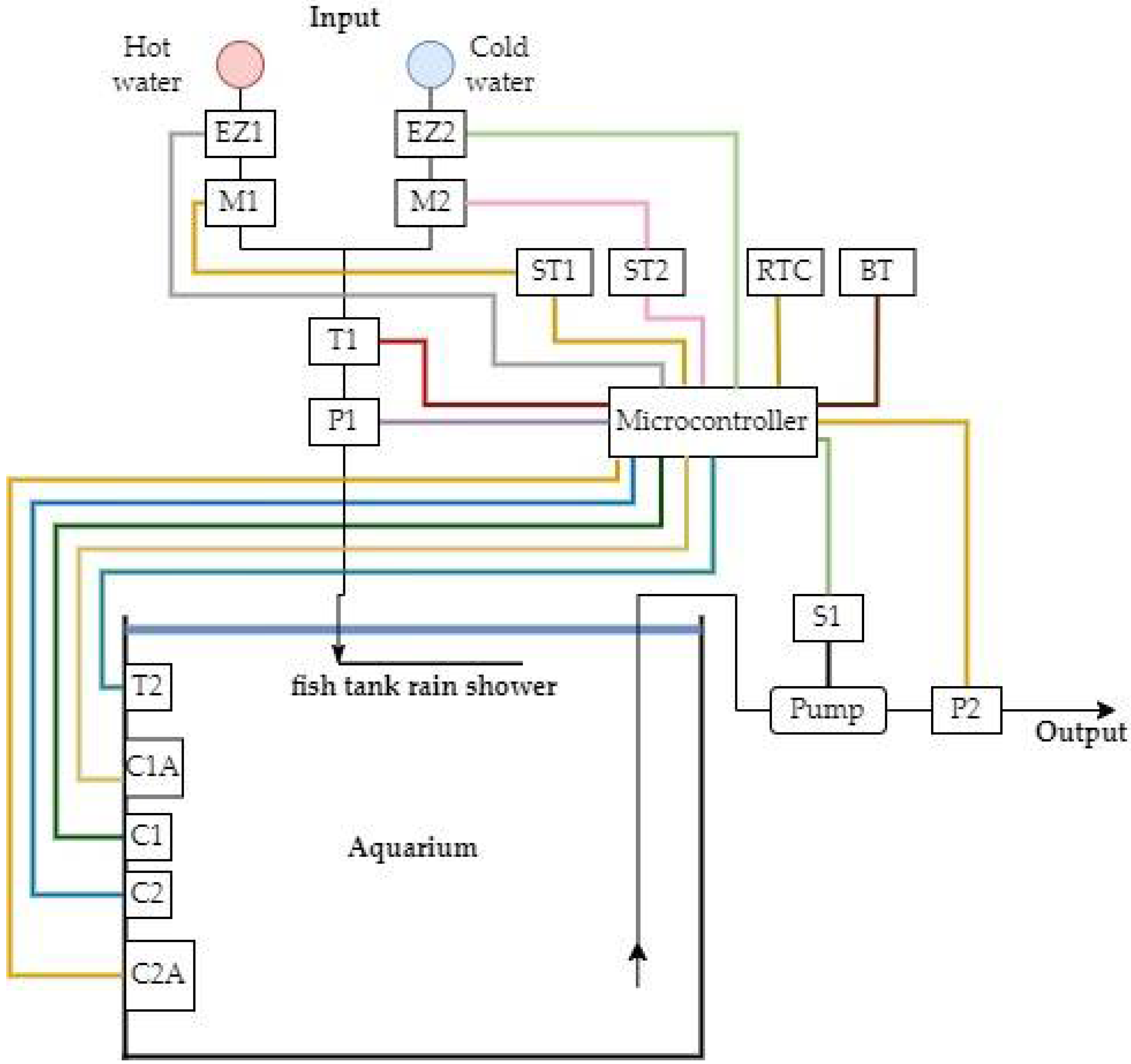
2.1. Specifications of the AWES

The developed automatic water exchange system consists of four closely related systems. These systems are the water discharge system, the water filling system, the data control system, and the security system. Figure 1 shows the schematic diagram of the AWES, and Figure 2 shows a simplified circuit diagram of the AWES.
These systems perform specific functions in the proper operation of the automatic water exchange system. They interact and complement each other; therefore, individual elements may occur in several systems simultaneously.
The water discharge system consists of an aquarium pump, relay S1, float liquid level sensors (C1, C2, C2A), and an emergency flow meter P2. The task of this system is to pump out water from the aquarium and to check the correctness of this process.
The water filling system consists of globe valves connected to stepper motors (M1, M2), stepper motor controllers (ST1, ST2), solenoid valves (EZ1, EZ2), temperature sensors (T1, T2), flow meter P1, float liquid level sensors (C1, C2, C1A) and a “sprinkler” (the last element of the system responsible for smooth and even distribution of the inflowed water into the aquarium).
The security system is used to protect the system from uncontrollable operating faults. The security system consists of emergency sensors C1A and C2A and an emergency flow meter P2. Sensor C1A is used to protect the water inflow system. This sensor duplicates the high state of the primary sensors (C1 and C2). On the other hand, sensor C2A and flow meter P2 are used to protect the water pouring system. In addition to controlling the quantity of water poured through P2, an emergency float sensor C2A is used. Like C2A, its function is to duplicate the signal of the primary sensors, but in this case, it is a logical low signal.
The last component of the AWES is the data control system. The data control system consists of a microcontroller and a dedicated mobile application. The microcontroller, as the “brain” of the whole system, is responsible for receiving data from sensors, processing received data, controlling actuators, and communicating with the user. The mobile application was created in such a way as to simplify the process of entering data by the user. The data entered are sent to the microcontroller via Bluetooth communication.

2.2. Operation of the AWES

To control the system, a dedicated application adapted to Android systems has been developed with the possibility of editing and changing the operating system. An example of the course of the operations performed is shown in Figure 3. This is a simplified algorithm for AWES operations.
The first step in ensuring proper functioning of the system is to check the communication condition between the mobile application and the microcontroller. If this event occurs, the reading and transferring of data from the mobile device to the microcontroller takes place. Otherwise, the actual part of the program that manages the system operation starts. The automatic water replacement system waits for the event that starts the water replacement process, which is the coincidence of the current date and time with the data entered by the user. The water exchange begins with the process of pouring water out of the aquarium as realized by the water discharge system. The water discharge system is responsible for controlling the operation of the aquarium pump and monitoring the current water level in the aquarium. The operation starts at the moment of the occurrence of an event that starts the water replacement process. The condition that terminates the water pour out operation is when the primary liquid level sensors reach a logically low state. This state informs the microcontroller that the water has been poured out of the aquarium and has reached the minimum set level. Further, in the operation of the automatic water filling system, the water filling process is started. The water filling process is implemented by the water filling system. The operation of filling water consists of proper control of the water flow and temperature. The valve settings should not exceed the set liquid flow rate and should achieve the user-defined temperature. The valves are controlled by stepper motors equipped with special designed caps.
The manuscript considers three methods of stepper motor control:
  • method 1 (dynamic)—abrupt temperature change, fastest temperature setting in time;
  • method 2 (mild, minimum ISE)—smooth temperature change, best possible reproduction of the setpoint. The requirement for the controller is the most accurate/precise representation of the setpoint;
  • method 3 (mixed without the PID regulator) consists of controlling the stepper motor settings on the basis of the error measured between the current temperature and the setpoint temperature.
Methods 1 and 2 use a PID controller. The task of the PID controller is to dynamically change the setpoint of the stepper motors. The change of this value depends on the values of temperature and water flow. These parameters are read in real time by sensors. The use of such a solution makes it possible to obtain the set-point value of temperature and water flow. In Method 1, when calculating the setpoints of the PID controller, the smallest possible error was taken into account, with the shortest possible system determination time.
In Method 2, the minimum ISE (Integral Squared Error) method was used in the selection of PID controller setpoints, which assumed the best representation of the setpoint.
The calculation of the settings of the various components of the PID controller is summarized in Table 1, in which the variable T represents the value of one period of the loop in the Arduino microcontroller and the variable τ specifies the delay taken as the time to take the first measurement.
Table 2 shows the values of the gains of the PID members that were adopted during the tests. The values were selected experimentally and based on the literature [25,26].
Method 3 did not use a PID controller, and the stepper motor settings were controlled based on the error measured between the current temperature and the setpoint temperature. The error value was not corrected for through gain values, which are used in a classic PID controller.
During the water filling operation, the liquid flow rate is measured by the flow meter P1. The completion of the water filling operation is triggered by the return of the basic liquid level sensors to a high logic state. When the water filling operation is complete, the water exchange process is terminated. All devices are set to their initial settings, and a function is run in the program to check if the starting condition occurred again. The last system that is part of the above system is the security system. Protections are programmed in such a way as to protect the system from damage and the living organisms in the aquarium from uncontrolled effects of system malfunction. The security system is closely connected to the previous two systems. It is responsible for protecting the aquarium from excessive pumping of water. This protection is achieved with an additional liquid level sensor, C2A. This sensor duplicates the logic state of the state represented by the primary sensors. The second part of this protection is an additional flow meter, P2, that checks the amount of water that is currently being poured out. If this value exceeds half of the aquarium volume declared by the user, the protection is triggered. The triggering of overpumping protection ends the process of pouring water. The consequence is the start of the water filling process. An additional safety device is also used in the water filling process. For this purpose, an additional emergency liquid level sensor C1A is used. This sensor is used when the water in the aquarium exceeds the high state and, at the same time, the basic sensors do not indicate the high logical state. A detailed algorithm of the above mentioned operations is shown in Figure 4.
The alarm states described above have been presented in tabular form in Table 3. The table also presents the actions performed by the system after the occurrence of each alarm state.
Table 4 shows the combinations of possible motions performed by the stepper motors that are responsible for controlling the flow and temperature of the water. The control of the stepper motors depends on the readings of the flow rate and the temperature of the liquid when the water filling process is performed. In the table below, clockwise (CW) rotation is used as the valve opening. Analogically, a counterclockwise (CCW) rotation was assumed to be the closing of the valve. The only condition where no motion is performed by any of the stepper motors is when the current temperature is the same as the set temperature and the current flow is less than or equal to the set flow.

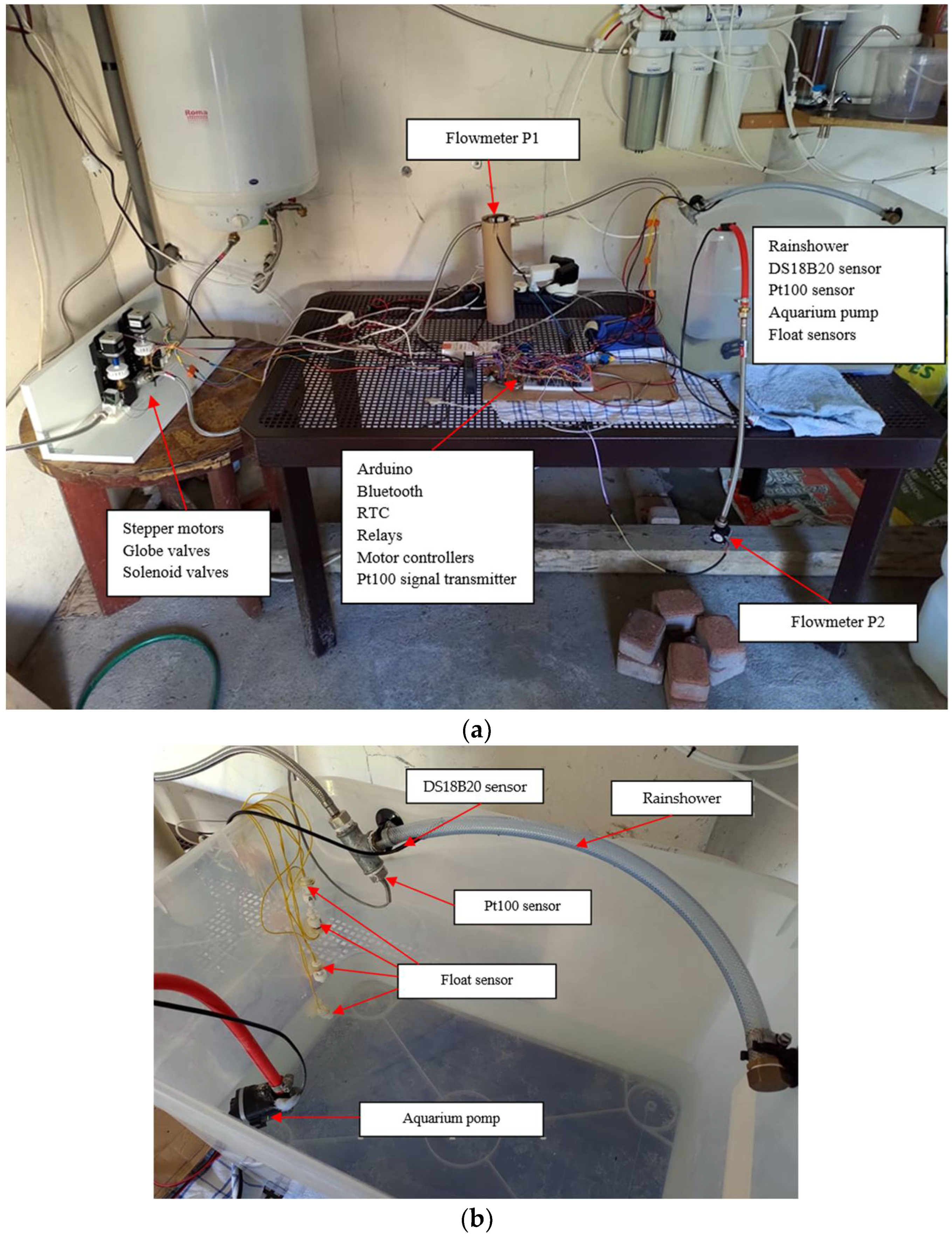
3. Experimental Setup

Figure 5 shows the test stand where the AWES prototype was tested. The test stand is divided into three parts. On the left side, there are elements responsible for controlling the filling of the aquarium with water. In the middle part, there are elements responsible for controlling the operation of the whole system. On the right side, there is a container representing an aquarium and sensors responsible for measuring the current level of the liquid and temperature. The AWES prototype (Figure 5) was assembled from the components listed in Table 5.
Next, the knob, stepper motor cap, and handle designed specifically for the project are presented. These elements were made to enable the system to work properly and increase its reliability and aesthetics. Figure 6 shows a photo of the physical elements used to control the water parameters.
Stepper motors were used to control globe valves. To correctly select the motor, a test was carried out on the force needed to move the valve handwheel. A NEMA 17 JK42HS48-0406 stepper motor was selected, which can generate 0.33 Nm of torque at 100 rpm. On the basis of this, a special cap and knob were designed to allow the motor and valve to be coupled. The cap has 15 tabs that are coupled to holes in a specially designed knob located on the valve. The force transmitted through each tab is approximately the amount of torque generated by the engine. Multiplying the tabs produced a force sufficient to move the knob. This combination allows for the efficient transmission of torque from the motor to the globe valve, and thus the unscrewing of the valve. These designed elements are shown in Figure 7.
The last component designed for the AWES is the design of the holder that allows the stepper motor to be mounted and connected to the globe valve. The design of the holder assumes the possibility of height adjustment of the motor position with a cap attached to it and an axial connection of the cap with the knob. The height of the motor can be locked by means of additional screws. The bracket allows the element to be fixed to a wall or other structure. The holder consists of a globe valve seat, a slide bar, a cover, and a mounting bracket dedicated to NEMA 17 stepper motors. The slide bar consists of a slider and a body in which the slider moves. The designs for the holder, cap, and knob were made in Autodesk Inventor and then printed on a 3D printer. The handle components are shown in the supplementary materials in Figure S1, while a simulation showing the combination of all previously shown components is shown in the supplementary materials in Figure S2.
To ensure proper operation and easier communication between the system and the user, a dedicated mobile application was designed and developed. The mobile application (Figure 8a) was created using the Android Studio program for phones with the Android operating system. The mobile application significantly simplifies the communication between the user and the automatic water exchange system. The application sends the data entered by the user through Bluetooth communication. The application has a simple and clear appearance, so its operation and thus management of the water exchange system are as simple as possible. In the application, the user, after a previous connection with the system, can enter data such as the day of the week, the time of change in water, the set temperature, and the size of the aquarium (Figure 8c). In addition to entering the data, the user can check the accuracy of the previously entered settings (Figure 8b).

4. Results and Discussion

The tests were conducted for three stepper motor control methods. The tests were started by entering the set parameters in the mobile application. Measurements were made for a heating and cooling cycle (heating from 25 °C to 30 °C, cooling from 30 °C to 25 °C). The measurements were made in the following order. The first step was to establish the system at an initial temperature of 25 °C. This was accomplished by performing one test cycle. This was followed by changing the setpoint temperature to a value of 30 °C. In this way, one heating cycle was performed. After the heating cycle was completed, the set point was changed to 25 °C. In this way, a cooling cycle was executed. At the end of the cooling cycle, the system returned to the initial value of 25 °C, so further cycles could be performed in sequence as described above. For each cycle, tests were performed five times, from which the average value was extracted at each time instant (test results were limited to 120 s). Then the stepper motor control method was changed. Measurements were made for all three methods. The measurement results for Method 3 are shown in Table 6 and Table 7.
Based on the results obtained during the tests, the best effects were claimed to have been obtained using method 1. This variant is characterized by the shortest settling time for the water heating state. Additionally, the settling time for the cooling temperature state is slightly worse than that for the other two methods. This method is characterized by the highest dynamics of parameter change, which affects large temperature changes. The worst method turned out to be method 3, which is characterized by the longest settling time for the heating state. However, this method proved to be the best method for measuring the cooling state of the water temperature. Method 3 is based on a small change in the temperature value of the inflowing water, which can result in a significant increase in the settling time with larger differences between the initial value and the set point of the water. Method 2 is an intermediate method between method 1 and method 3. Similarly to method 3, it is characterized by soft changes in the value of water temperature. On the other hand, due to the application of the PID regulator, it allows determining the set parameters more dynamically and, what follows, faster than method 3. It is a method that allows for a quick and smooth transition from the initial conditions to the set conditions. The time to establish the set-point temperature correlates strongly with the temperature value of the water that is in the water supply network. Significant differences in the measurement results are due to the limitations of the presented system. The applied measurement sensors are characterized by their measurement error at a 0.1 °C level, which significantly influences the measurements with a very narrow margin of error. Additionally, the system continuously corrects the values read from the sensors and adjusts the settings of the stepper motors. This affects the various combinations of stepper motor movements so that maximum extreme results may occur. However, the averaged results of the conducted tests well reflect the actual operation of the presented system with the use of individual motor control methods. A comparison of individual methods of temperature and water flow control is presented in Table 8.
The graphs in Figure 9 and Figure 10 represent a graphical representation of the average values from the five measurements taken for each method. Figure 9 shows a graph of the control methods for the cooling water condition, and Figure 10 shows a graph of the control methods for the heating water condition.
The results of the test show that regardless of the selected stepper motor control method, the system settling times are comparable. The protection system also increases work safety and protects the system from damage.
In general, the composition of the water in aquariums changes constantly. This is caused by the metabolic products of living organisms. An aquarium is a closed system in which water, being a very good solvent, absorbs and dissolves all, both good and bad, chemical compounds in it for so long until its ability to dissolve substances is exhausted. The problem is that fish and other aquatic animals, including shrimp, are very sensitive to even seemingly trace amounts of harmful substances, including ammonium compounds. That is why it is so important to regularly change the water in aquariums. This removes some of the “used” water from the tank and provides the aquarium with a portion of fresh, healthier water. When doing so, it is important to ensure that the replenished water has parameters similar to the water in the aquarium and that it is not contaminated from the outside with chemicals. The developed AWES system allows one to regularly change the water in the aquarium, which significantly affects the reduction of ammonia.

5. Conclusions

In the paper, a practical model for water exchange is proposed that can be easily implemented, increasing the work efficiency of the aquarist. Thanks to the use of the AWES, it is possible to effectively and easily regulate the flow of water and control the water temperature. The developed AWES system allows for regular changing of water in aquariums, which has a significant impact on reducing ammonia.
The developed system, due to the application of simple, durable, and inexpensive components, combines low price and low exploitation costs. The system has been designed in such a way that it consumes as little electrical energy as possible while waiting for the water exchange function to be performed. The created system is characterized by precise, repeatable, and correct work. The stability of the system is strongly dependent on the temperature of the water in the water installation.
The presented water exchange system can be extended in the future with a system that controls light, feeding, mechanical aquarium cleaning, and measuring basic water parameters (pH, water hardness, salinity, nitrate, or phosphate levels). Additionally, the system can be equipped with additional GMS or Wi-Fi communication systems that will further improve security and communication with the user. Another direction of development may be the use of a waterproof camera for real-time monitoring of life in the aquarium. It is also worth remembering the potential directions of additional protection for the system, such as additional covers for float sensors (protecting the sensors from being blocked) or additional disconnection of devices working in the aquarium (filter and heater) for the time of water change. This protects the devices mentioned above from damage and the user from electric shocks.
In conclusion, the developed water exchange system fully modernizes the aquarist’s work in maintaining the tank in natural balance. Additionally, it allows for further development of the system, which, in the future, may make it possible to create an aquarium fully independent of human interference.

Supplementary Materials

The following supporting information can be downloaded at: https://www.mdpi.com/article/10.3390/electronics11172705/s1, Figure S1: Components of the coupling bracket (a) socket; (b) slide bar; (c) cover; (d) mounting bracket, Figure S2: Assembled handle with stepper motor and globe valve (a) front site; (b) back site.

Author Contributions

Conceptualization, D.S. and P.H.; methodology, D.S. and P.H.; software, P.H.; validation, D.S. and P.H.; formal analysis, D.S. and P.H.; investigation, D.S. and P.H.; resources, P.H.; data curation, P.H.; writing—original draft preparation, D.S. and P.H.; writing—review and editing, D.S. and P.H.; visualization, P.H.; supervision, D.S.; project administration, D.S. and P.H.; funding acquisition, D.S. and P.H. All authors have read and agreed to the published version of the manuscript.

Funding

This research was funded by the Polish Government, grant number 0212/SBAD/0568.

Conflicts of Interest

The authors declare no conflict of interest.

References

  1. Pasha Mohd Daud, A.K.; Sulaiman, N.A.; Mohamad Yusof, Y.W.; Kassim, M. An IoT-based smart aquarium monitoring system. In Proceedings of the 2020 IEEE 10th Symposium on Computer Applications & Industrial Electronics (ISCAIE), Penang, Malaysia, 18–19 April 2020; pp. 277–282. [Google Scholar]
  2. Novák, J.; Kalous, L.; Patoka, J. Modern Ornamental Aquaculture in Europe: Early History of Freshwater Fish Imports. Rev. Aquac. 2020, 12, 2042–2060. [Google Scholar] [CrossRef]
  3. Duraibabu, D.B.; Leen, G.; Toal, D.; Newe, T.; Lewis, E.; Dooly, G. Underwater Depth and Temperature Sensing Based on Fiber Optic Technology for Marine and Fresh Water Applications. Sensors 2017, 17, 1228. [Google Scholar] [CrossRef] [PubMed]
  4. Hilal, Y.Y.; Khessro, M.K.; van Dam, J.; Mahdi, K. Automatic Water Control System and Environment Sensors in a Greenhouse. Water 2022, 14, 1166. [Google Scholar] [CrossRef]
  5. Saparudin, F.A.; Chee, T.C.; Ghafar, A.S.A.; Majid, H.A.; Katiran, N. Wireless Water Quality Monitoring System for High Density Aquaculture Application. Indones. J. Electr. Eng. Comput. Sci. 2019, 13, 507–513. [Google Scholar] [CrossRef]
  6. Manoj, M.; Dhilip Kumar, V.; Arif, M.; Bulai, E.-R.; Bulai, P.; Geman, O. State of the Art Techniques for Water Quality Monitoring Systems for Fish Ponds Using IoT and Underwater Sensors: A Review. Sensors 2022, 22, 2088. [Google Scholar] [CrossRef] [PubMed]
  7. Pelletier, D.; Rouxel, J.; Fauvarque, O.; Hanon, D.; Gestalin, J.-P.; Lebot, M.; Dreano, P.; Furet, E.; Tardivel, M.; Le Bras, Y.; et al. KOSMOS: An Open Source Underwater Video Lander for Monitoring Coastal Fishes and Habitats. Sensors 2021, 21, 7724. [Google Scholar] [CrossRef] [PubMed]
  8. Lin, Y.-B.; Tseng, H.-C. FishTalk: An IoT-Based Mini Aquarium System. IEEE Access 2019, 7, 35457–35469. [Google Scholar] [CrossRef]
  9. Chiu, M.-C. A Multi-Functional Aquarium Equipped with Automatic Thermal Control/Fodder-Feeding/Water Treatment Using a Network Remote Control System. Inf. Technol. J. 2010, 9, 1458–1466. [Google Scholar] [CrossRef]
  10. Sung, W.-T.; Chen, J.-H.; Wang, H.-C. Remote Fish aquaculture monitoring system based on wireless transmission technology. In Proceedings of the 2014 International Conference on Information Science, Electronics and Electrical Engineering, Sapporo, Japan, 26–28 April 2014; Volume 1, pp. 540–544. [Google Scholar]
  11. Wang, C.; Li, Z.; Wang, T.; Xu, X.; Zhang, X.; Li, D. Intelligent Fish Farm—the Future of Aquaculture. Aquacult Int. 2021, 29, 2681–2711. [Google Scholar] [CrossRef] [PubMed]
  12. Yanong, R. Fish Health Management Considerations in Recirculating Aquaculture Systems—Part 3: General Recommendations and Problem-Solving Approaches. EDIS 2004, 2004, 1–9. [Google Scholar] [CrossRef]
  13. Yanong, R. Fish Health Management Considerations in Recirculating Aquaculture Systems—Part 2: Pathogens. EDIS 2004, 2004, 1–8. [Google Scholar] [CrossRef]
  14. Yanong, R. Fish Health Management Considerations in Recirculating Aquaculture Systems—Part 1: Introduction and General Principles. EDIS 2004, 2004, 1–9. [Google Scholar] [CrossRef]
  15. Jepson, L. A Practical Guide to Keeping Healthy Fish in a Stable Environment; Barron’s: Hauppauge, NY, USA, 2001; ISBN 978-0-7641-5277-1. [Google Scholar]
  16. Grow, S.; Lyles, A.M.; Greenberg, R.; Powell, D.M.; Dorsey, C. Zoos, Aquariums, and Zoological Parks. In Reference Module in Life Sciences; Elsevier: Amsterdam, The Netherlands, 2022; ISBN 978-0-12-809633-8. [Google Scholar]
  17. Garcia-Pineda, M.; Sendra, S.; Lloret, G.; Lloret, J. Monitoring and Control Sensor System for Fish Feeding in Marine Fish Farms. Commun. IET 2011, 5, 1682–1690. [Google Scholar] [CrossRef]
  18. Balasubramani, S.; Aakash, S.; Akshay, B.; Bennet, N. Smart Aquarium Management System. Adv. Parallel Comput. 2020, 37, 523–527. [Google Scholar] [CrossRef]
  19. El Shal, A.M.; El Sheikh, F.M.; Elsbaay, A.M. Design and Fabrication of an Automatic Fish Feeder Prototype Suits Tilapia Tanks. Fishes 2021, 6, 74. [Google Scholar] [CrossRef]
  20. Noor, M.Z.H.; Hussian, A.K.; Saaid, M.F.; Ali, M.S.A.M.; Zolkapli, M. The Design and Development of Automatic Fish Feeder System Using PIC Microcontroller. In Proceedings of the 2012 IEEE Control and System Graduate Research Colloquium, Shah Alam, Selangor, Malaysia, 16–17 July 2012; pp. 343–347. [Google Scholar]
  21. Shin, K.J.; Angani, A.V. Development of water control system with electrical valve for smart aquarium. In Proceedings of the 2017 International Conference on Applied System Innovation (ICASI), Sapporo, Japan, 13–17 May 2017; pp. 428–431. [Google Scholar]
  22. Gong, S.; Angani, A.; Shin, K.J. Realization of fluid flow control system for vertical recycling aquatic system (VRAS). In Proceedings of the 2018 International Symposium on Computer, Consumer and Control (IS3C), Taiwan, China, 6–8 December 2018; pp. 185–188. [Google Scholar]
  23. Ullah, I.; Kim, D. An Optimization Scheme for Water Pump Control in Smart Fish Farm with Efficient Energy Consumption. Processes 2018, 6, 65. [Google Scholar] [CrossRef] [Green Version]
  24. Lee, J.; Angani, A.; Thalluri, T.; Shin, K.J. Realization of Water Process Control for Smart Fish Farm. In Proceedings of the 2020 International Conference on Electronics, Information, and Communication (ICEIC), Barcelona, Spain, 19–22 January 2020; pp. 1–5. [Google Scholar]
  25. Kabziński, J. Teoria Sterowania; PWN: Warsaw, Poland, 2021; ISBN 978-83-01-21705-1. [Google Scholar]
  26. Silva, G.J.; Datta, A.; Bhattachaiyya, S.P. (Eds.) Control system design using the pid controller. In PID Controllers for Time-Delay Systems; Control Engineering; Birkhäuser: Boston, MA, USA, 2005; pp. 191–222. ISBN 978-0-8176-4423-9. [Google Scholar]
Figure 1. Schematic diagram of the AWES. C1, C2—float liquid level sensors; C1A, C2A—emergency float liquid level sensors; P1—flow meter, P2—emergency flow meter; T1, T2—temperature sensors; M1, M2—stepper motors; ST1, ST2—stepper motor controllers; EZ1, EZ2—solenoid valves; S1—relay; RTC—Real-Time Clock, BT–Bluetooth module.
Electronics 11 02705 g001
Figure 2. Simplified circuit diagram of the AWES.
Electronics 11 02705 g002
Figure 3. Simplified diagram of how the AWES works.
Electronics 11 02705 g003
Figure 4. Operating diagram of the AWES.
Electronics 11 02705 g004
Figure 5. Test stand for the AWES (a); container representing an aquarium and sensors responsible for measuring the current level of the liquid and temperature (b).
Electronics 11 02705 g005
Figure 6. Picture showing stepper motors, globe valves, and solenoid valves.
Electronics 11 02705 g006
Figure 7. Designed components: cap (a); knob (b).
Electronics 11 02705 g007
Figure 8. Mobile application: (a) mobile application start screen; (b) mobile application connection screen; (c) data entry screen.
Electronics 11 02705 g008
Figure 9. Comparison of control methods for the water cooling condition in terms of average temperature in time.
Electronics 11 02705 g009
Figure 10. Comparison of control methods for the water heating condition in terms of average temperature in time.
Electronics 11 02705 g010
Table 1. Calculation of PID controller gains.
Regulation PrincipleControl PControl IControl D
method 1 0.35 T τ 2.4   τ 0.4   τ
method 2 0.3 T τ 1.3   τ 0.5   τ
Table 2. PID controller gain values.
MethodKpKiKd
method 11.42.40.4
method 21.21.30.5
Table 3. Alarm states.
AlarmMeasuring SignalAction
Low water levelEmergency float switch lower (C2A) in closed position or total evacuated water ≥ half of the aquarium volumeStopping the aquarium pump
Light signal
Switching to the water filling function
High water levelUpper emergency float sensor (C1A) in open positionClose the solenoid valves
Stopping stepper motors
End of the water filling process
Table 4. Possible movements of stepper motors responsible for water flow and temperature control.
Temperature\FlowCurrent Flow ≤ Set FlowCurrent Flow > Set Flow
Current temp. > Set temp.Motor Hot Water Stop
Motor Cold Water CW Rotation
Motor Hot Water CCW Rotation
Motor Cold Water Stop
Current temp. < Set temp.Motor Hot Water CW Rotation
Motor Cold Water Stop
Motor Hot Water Stop
Motor Cold Water CCW Rotation
Current temp. = Set temp.Motor Hot Water Stop
Motor Cold Water Stop
Motor Hot Water CCW Rotation
Motor Cold Water CCW Rotation
Table 5. List of components used for the AWES prototype. The additional parts of the AWES system, such as a knob, a cap, clutches, or handles, are not detailed here.
No. Hardware/Software SpecificationDescription
1.stepper motors NEMA 17
JK42HS48-0406
A stepper motor was used to control the fluid flow, with a specially designed cap to allow the globe valve to rotate. The motor was selected based on a study of the torque required to move the globe valve. On the basis of this, a special cap and knob were designed to allow the motor and valve to be coupled.
2.globe valvesGlobe valves are suitable for manual and automatic operation. They can be used to regulate the flow or pressure, as well as to completely shut off the flow.
3.solenoid valvessolenoid valves to cut off water supply.
4.microcontroller Arduino Mega 2560The Arduino Mega 2560 is an open source microcontroller board based on the ATmega2560 and developed by Arduino.cc. The board is equipped with sets of digital and analogue input/output (I/O) pins that can be connected to various expansion shields. It is responsible for controlling components, receiving and processing signals, and communication.
5.bluetooth module HC-06The Bluetooth module is responsible for communication between the microcontroller and a dedicated mobile application.
6.RTC module
DS1307
The RTC module is responsible for storing information about the current date and time. Equipped with a battery, it allows settings to be remembered during a power failure. The circuit also allows for the connection of a DS18B20 temperature sensor.
7.stepper motor driver A4899The stepper motor driver A4899 enables control of the motor rotation direction, resolution of preset steps, and allows the system to enter sleep mode.
8.temperature sensor DS18B20A DS18B20 sensor is connected to the RTC module. The sensor is mounted inside the rainshower, which makes it possible to measure the water temperature directly in front of the aquarium.
9.temperature sensor Pt100Reads the water temperature. The purpose of the Pt100 sensor is to verify the correct operation of the DS18B20 sensor.
10.aquarium pumpAn aquarium pump was used to pump out the water. The size of the pump depends on the size of the aquarium. The use of different pump sizes allows different amounts of water to be pumped out in the shortest possible time, regardless of the size of the aquarium.
11.relaysA dedicated relay board was used to control the pump. The choice of this component allows for simple control of electrical devices that require a power supply greater than that available from the microcontroller. Additionally, the relay protects both the microcontroller and the peripheral from damage resulting from overvoltage or an incorrect power supply.
12.float sensorsFloat sensors are characterized by good measurement uncertainty and accuracy. The principle of these sensors does not adversely affect the behavior of aquatic animals, and they are simple and inexpensive.
13.flowmeter
YF-S201
The flowmeter is responsible for reading the current liquid flow rate and sending information to the microcontroller. Depending on sensor readings, the water flow is controlled by stepper motors.
14.mobile devices/AndroidTo support mobile applications.
15.operating system/WindowsThe operating system to be installed on the computer that can be used for programming.
Table 6. Water cooling status.
Time [s]Measure 1 [°C]Measure 2 [°C]Measure 3 [°C]Measure 4 [°C]Measure 5 [°C]Average [°C]
1527.126.927.126.826.226.82
1626.927.027.226.926.026.80
1727.127.126.926.926.126.82
1827.027.126.826.225.826.58
1927.127.027.126.025.926.62
2027.126.926.925.926.026.56
2126.226.927.026.125.926.42
2226.127.027.126.225.926.46
2326.026.927.126.125.226.26
2425.927.026.926.026.226.40
2526.127.027.026.026.026.42
2625.927.127.025.826.126.38
2725.926.927.225.926.126.40
2826.026.927.126.025.926.38
2926.126.326.226.226.126.18
3025.926.226.126.026.026.04
3125.826.026.226.125.926.00
3226.126.026.126.025.826.00
3326.025.926.125.826.125.98
3425.925.926.026.126.226.02
3526.026.125.926.126.026.02
3626.126.026.026.126.126.06
Table 7. Water heating status.
Time [s]Measure 1 [°C]Measure 2 [°C]Measure 3 [°C]Measure 4 [°C]Measure 5 [°C]Average [°C]
1525.927.627.828.628.127.60
1625.927.928.128.828.027.74
1726.027.828.829.028.227.96
1826.428.028.829.628.228.20
1926.828.129.029.829.128.56
2027.027.929.430.229.128.72
2126.928.229.530.830.029.08
2227.028.229.930.930.029.20
2327.428.830.031.431.129.74
2427.928.930.632.031.130.10
2527.829.030.632.031.230.12
2628.029.030.832.131.130.20
2728.228.930.632.031.230.18
2828.829.030.731.931.230.32
2929.029.130.731.831.130.34
3029.129.130.631.931.030.34
3129.029.030.732.029.930.12
3229.128.930.731.631.030.26
3329.129.030.831.431.030.26
3429.029.130.831.231.030.22
3529.229.030.631.031.130.18
3629.129.030.831.031.030.18
Table 8. Results of testing the stability of the AWES.
MeasureMethod 1Method 2Method 3
CoolingHeatingCoolingHeatingCoolingHeating
Entry 117 s23 s21 s18 s23 s30 s
Entry 224 s22 s41 s22 s31 s25 s
Entry 324 s21 s19 s21 s30 s19 s
Entry 437 s21 s23 s24 s20 s34 s
Entry 527 s20 s22 s28 s17 s21 s
Average time to determination25.8 s21.4 s25.2 s22.6 s24.6 s25.8 s
Publisher’s Note: MDPI stays neutral with regard to jurisdictional claims in published maps and institutional affiliations.

