Article

Local-Partial Signal Combining Schemes for Cell-Free Large-Scale MU-MIMO Systems with Limited Fronthaul Capacity and Spatial Correlation Channels

by
Amr A. Alammari
1,*,
Mohd Sharique
1,
Athar Ali Moinuddin
1 and
Mohammad Samar Ansari
2
1
Department of Electronics Engineering, Zakir Hussain College of Engineering & Technology, Aligarh Muslim University, Aligarh 202002, India
2
Faculty of Science and Engineering, University of Chester, Parkgate Road, Chester CH1 4BJ, UK
*
Author to whom correspondence should be addressed.
Electronics 2022, 11(17), 2757; https://doi.org/10.3390/electronics11172757
Submission received: 11 August 2022 / Revised: 18 August 2022 / Accepted: 23 August 2022 / Published: 1 September 2022
(This article belongs to the Section Microwave and Wireless Communications)

Abstract

:
Cell-free large-scale multi-user MIMO is a promising technology for the 5G-and-beyond mobile communication networks. Scalable signal processing is the key challenge in achieving the benefits of cell-free systems. This study examines a distributed approach for cell-free deployment with user-centric configuration and finite fronthaul capacity. Moreover, the impact of scaling the pilot length, the number of access points (APs), and the number of antennas per AP on the achievable average spectral efficiency are investigated. Using the dynamic cooperative clustering (DCC) technique and large-scale fading decoding process, we derive an approximation of the signal-to-interference-plus-noise ratio in the criteria of two local combining schemes: Local-Partial Regularized Zero Forcing (RZF) and Local Maximum Ratio (MR). The results indicate that distributed approaches in the cell-free system have the advantage of decreasing the fronthaul signaling and the computing complexity. The results also show that the Local-Partial RZF provides the highest average spectral efficiency among all the distributed combining schemes because the computational complexity of the Local-Partial RZF is independent of the UTs. Therefore, it does not grow as the number of user terminals (UTs) increases.

1. Introduction

Fifth-generation (5G) and beyond technology has been developed to meet the constant demand for reliable wireless services with higher data rates [1]. It is projected that 5G-and-beyond systems will be able to connect and manage an unprecedented number of devices and provide ubiquitous services [2]. In order to address the design challenges of 5G-and-beyond, several key technologies are being investigated [3,4,5,6,7,8,9,10,11]. Some of the candidate technologies proposed for the 5G-and-beyond mobile communication networks include reconfigurable intelligent surface [4], SLNR-based beamforming [6], millimeter wave [7,8], advanced multiple access [9,11], and large-scale multi-user multiple input multiple output (MU-MIMO). Due to its ability to minimize interference, large-scale MU-MIMO can provide several orders of magnitudes of improvement in the system’s spectral efficiency.
A recently developed concept, known as cell-free large-scale MU-MIMO, provides a novel network architecture based on three well-known technologies: large-scale MU-MIMO [12,13,14,15,16,17,18], Coordinated Multi-Point (CoMP) [19], and Distributed Antenna System (DAS) [20,21]. Cell-free large-scale MU-MIMO has been proposed as a potential alternative to dividing up the coverage area into cells.
Compared to the conventional cellular network layout, cell-free network layout eliminates the cell borders and the resulting inter-cell interference [22,23]. In the cell-free system, a large number of access points (APs), distributed in the area of coverage, provide services to a large number of users. All APs in this system deployment use fronthaul links to communicate with a central processing unit (CPU). The CPU manages and coordinates all the transmissions in the network.
There are typically two implementation approaches for cell-free systems [24,25,26,27]: completely centralized and distributed. In the centralized approach, all signal processing is performed at the CPU. All APs forward the received pilot and data signals to the CPU, which will carry out the necessary processing. Taking into account the practical constraints of having links with limited fronthaul capacity, this approach typically leads to unmanageable fronthaul signaling.
In the distributed cell-free implementation, the required signal processing is shared between the CPU and the APs, and depending on the amount of this sharing, different levels of distribution can be accomplished. The initial concept for cell-free is developed on the basis of two primary assumptions: all the active UTs in the network are served by all the APs simultaneously [28,29] and availability of unlimited capacity for the fronthaul links [30,31].
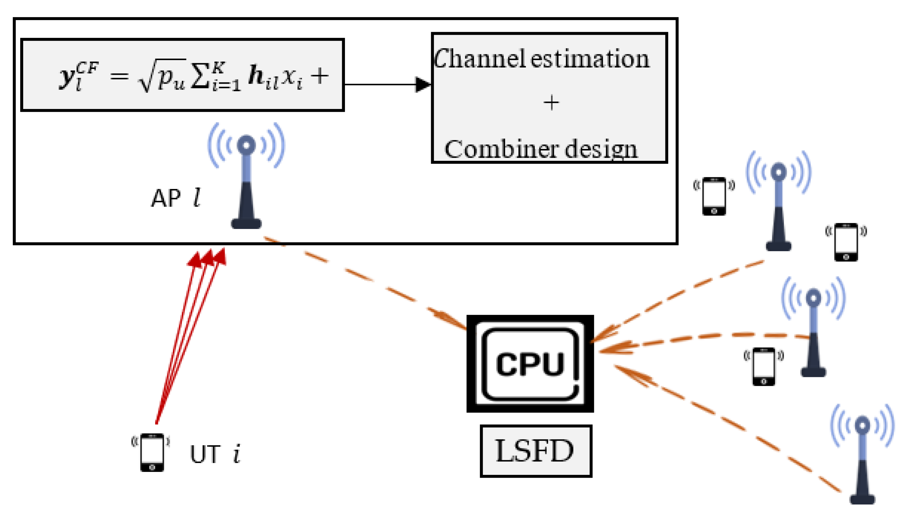
In large-scale MU-MIMO, the maximum sum spectral efficiency (SE) that can be achieved is constrained by two factors: wireless channel capacity and fronthaul link capacity [32]. The distributed approach can be used to achieve a reduction in the fronthaul requirements [33]. In this architecture, some baseband signal processing is performed at the APs. Motivated by the above argument, this paper considers the system uplink performance with limited fronthaul capacity and different local distributed combining schemes. The distributed implementation adopted in this paper is distinguished from the centralized implementation by the following:
(1)
The channel estimation process is performed locally at each access point;
(2)
Combiner design and data estimation are performed locally at each access point;
(3)
APs use the fronthaul links to send the data estimates only;
(4)
An additional stage of data estimation is performed centrally by the CPU.

1.1. Related Work

Recently, cell-free systems have attracted great interest, and many previous studies have evaluated their performance from various perspectives [22,24,26,27,28,29,30,31,32,33,34,35,36,37,38,39,40,41,42,43,44,45]. For instance, in [22], the sum spectral efficiency for Maximum Ratio beamforming/combining has been derived. A stochastic geometry technique was employed in [34] to evaluate the system performance. Additionally, [36] studied a cell-free system with power optimization and precoding technique to enhance the network data rate. The fully centralized approach of a cell-free system, in which the estimation process and combiner design are performed centrally, is investigated in [27,37]. Distributed implementations are considered in [38] in order to reduce the fronthaul traffic.
In order to make the analysis more manageable, most of the previous studies consider a wide variety of simplifying assumptions, including the following:
  • All users are served by all APs in the same time-frequency resources: For example, authors in [39] investigated the achievable uplink rate performance of the cell-free systems with perfect/imperfect CSI and Zero Forcing (ZF) processing. However, in practice and as a result of this assumption, the system will not be scalable, implying that the system will be unable to manage an increasing number of active UTs and APs. Furthermore, this configuration is impractical since only a limited number of APs can beneficially communicate with a particular UT. To address these constraints and maintain scalability, we consider a practical system configuration that allows UTs to dynamically choose their subset of APs. Thus, a group of nearby APs are cooperatively serving each UT, as shown in Figure 1. In this user-centric configuration, a clustering technique known as Dynamic Cooperative Clustering (DCC) is used, which allows UTs to choose their preferred set of serving APs. With the DCC approach, the scalability comes from the fact that only the UT’s corresponding subset of APs will be involved in the signal processing. The works in [40,41] have investigated a user-centric configuration for cell-free systems with different channel estimators. However, these studies are based on simple beamforming/combining schemes with some idealized assumptions.
  • Unlimited fronthaul/backhaul link capacity: For example, the authors in [42] investigate the downlink of a cell-free system considering power control technique and the ZF process. However, each fronthaul/backhaul connection will have a finite capacity when dealing with practical systems. Moreover, to achieve scalability, it is necessary to restrict the fronthaul signaling between the APs and the CPU. The authors in [43] investigated the impact of using capacity constrained fronthaul links on the average max–min rate per user, considering low-complexity hybrid precoders/decoders. However, the study focuses on the centralized case where the baseband processing of the transmitted signals is fully performed at the CPU. We investigate the uplink of a cell-free large-scale MU-MIMO system with distributed implementation, limited fronthaul links, and the DCC approach.
  • The propagation channels are spatially uncorrelated: For example, studies in [44,45] analyzed the system performance under independent Rayleigh channels using general models such as uncorrelated Rayleigh fading. However, in practice, the correlation between the antenna elements is inherent in the implementation of the cell-free system due to the large number of APs. For a realistic performance investigation of cell-free systems, a physical correlated channel model is considered in this paper.

1.2. Contributions

By investigating the local distributed user-centric approach of a cell-free system with finite fronthaul links Capacity, the main contributions of our work include the following:
  • Uplink System modeling: In this paper, we consider the uplink scenario of a user-centric cell-free system with finite capacity fronthaul links to investigate the impact of distributing the signal processing between the APs and the CPU for achieving a certain level of performance. The distributed system implementation is modeled and numerically simulated. The goal of this research is to provide a further understanding of partial local distributed cell-free systems under more realistic system considerations.
  • Analysis of distributed implementations for user-centric cell-free system: Two system configurations, namely, locally distributed and two-stage distributed, are considered to study how competitive these configurations are to a centralized-based system configuration vis-à-vis the achieved SE. Extensive simulations have been performed to evaluate the system’s performance from different perspectives, including the effect of increasing the pilot length, APs number, and APs’ antennas for the three schemes: Partial RZF, Local-Partial RZF, and Distributed MR.
  • Distributed Physical layer processing: The essential local physical layer procedures in the distributed user-centric cell-free uplink transmission, such as pilot signaling, channel estimation, and data detection, are identified. Using different bounding techniques, we derive an approximation for the effective SINR using the clustering concept and the large-scale fading decoding (LSFD)scheme.

1.3. Paper Organization

The remaining parts of this work are structured as follows: The user-centric cell-free large-scale MU-MIMO system model is described in Section 2. In Section 3, computational complexity and fronthaul signaling are analyzed. In Section 4, a physical geometric-based channel model which is considered in this paper is presented. Simulation results and discussion are presented in Section 5, followed by concluding remarks in Section 6.

2. System Model

We consider a cell-free system with K single-antenna user terminals (UTs), which are served by L access points (APs), and all the UTs and the APs are distributed randomly in the coverage area. Let N be the number of antennas per AP. The system satisfies the user-centric condition, where a set of APs, Q k { 1 , 2 , , L } cooperate to serve an arbitrary UT k. Furthermore, we consider a block fading model, where all the channels are considered to be static and frequency flat within a single block (known as the coherence block) and vary among different blocks.
The coherence block size is determined by many factors, including carrier frequency, mobility, propagation environment, etc. Further, in this block fading model, each coherence block is divided into τ p channels used for the uplink pilot training, τ u for sending data on the uplink, and τ d channels for sending the data on the downlink. Let h denote the channel response between the k t h UT and the L t h AP, and the channel realization is drowned from an independent correlated Rayleigh fading distribution as
h k l ~   N C   ( 0 , R k l )
where R represents the spatial correlation matrix, which contains the small-scale fading as well as the large-scale fading. In the block fading model, the small-scale effect can be static in one coherence block, and it may change among different blocks. On the other hand, the effect of large-scale fading is considered to be changing more slowly and can be regarded as constant for a number of coherence blocks.
We consider the distributed implementation given in Figure 2, and the operations of interest in this paper include uplink training, channel estimation, combiner design, and data detection.

2.1. Uplink Training and Channel Estimation

In the training stage, all the UTs send their pilots to the APs throughout a pilot-based training process. The training pilots are known as the pilot sequence, and the network is assumed to have τ p available orthogonal pilot sequences. However, it is expected that the number of active UTs will be more than the number of available orthogonal sequences ( K > τ p   ) . This will make several UTs reuse the same pilot sequences in their analyses. The term “pilot contamination” refers to a problem that occurs in the large-scale MU-MIMO networks when multiple UTs use the same pilot sequences. The received pilot signal at the AP l can be given as
y l p i l o t = p p i = 1 K h i l   ψ t i H + W l
where p p is the transmitted pilot power, W l is the additive independent white Gaussian noise matrix with independent and identically distributed N   ( 0 , σ 2 ) elements, ψ t i H is the pilot sequence sent by the k t h UT and t = 1 , , τ p .
Based on the received pilot signal in Equation (2), the AP l performs the channel estimation process. The LMMSE estimator is employed in each AP to estimate the channel coefficients to the UTs. The estimated channel between the UT k , and the AP l is given as [17]
h ^ i l = p p τ p R i l Q c o r r   y t l p i l o t
where R i l denotes the spatial correlation matrix, i Q k , and Q c o r r denotes the inverse of the normalized correlation matrix.
The difference between the channel and its estimate is known as the estimation error and can be termed as e i l = h i l h ^ i l . The covariance matrices of both h ^ i l and e i l for the cell-free distributed implementation can be given as follows
C est . = p p τ p R i l Q c o r r   y t l p i l o t R i l
C err . = R i l p p τ p R i l Q c o r r   y t l p i l o t R i l  
In the distributed implementation and in contrast to the analysis for the centralized implementation, the channel statistics from UT k to its connected APs will be used locally at each AP for designing the combiner and estimating the transmitted signal.

2.2. Combiner Design and Signal Detection

After the channels are estimated locally at the APs, the UTs transmit their data symbols. The received signals are processed at each APs to detect the desired signal x ^ k . The detection process in the distributed approach involves two stages of data estimation:
First, based on Equation (2), the transmitted signals can be estimated locally at the APs by applying a linear combiner as
x ^ l , k = a l , k   y l C F = a l , k H h l , k x k + i = 1 i k K a l , k H h l , i x i + a l , k H w l
where a l , k represents the combiner that contains vectors from all APs that communicate with the UT k. Note that the detection process in the user-centric approach is constrained to a subset of APs (i.e., Q k { 1 , 2 , , L } ) corresponding to the UT k.
Then, based on Equation (6), another stage of signal estimation is performed centrally by the CPU. This process is known as large-scale fading decoding (LSFD), which involves using the LSFD weight vector { v l , k : l = 1 , ,   L } to estimate the data symbols as
    x ^ k = l = 1 L v l , k * x ^ l , k  
x ^ k = l = 1 L v l , k * a l , k H h l , k x k + l = 1 L v l , k * a l , k H i = 1 i k K h l , i x i   l = 1 L v l , k * a l , k H w l
In general, the ergodic capacity of the large-scale MU-MIMO system has not yet been defined. However, different bounds on the capacity are available. These bounds are also known as achievable SE and can be used to evaluate the system performance. In this paper, a lower bound technique is used to study the uplink system performance with local distributed combing schemes. Following the same argument in [33], the uplink achievable SE of UT k for the user-centric cell-free system can be given as
S E k C F = ( 1 τ p τ c ) E   { l o g 2 (   1 + S I N R k C F ) }
where SINR is the effective signal to interference and noise ratio, which can be given as
S I N R k = p k | v k H E { g k , k } | 2 i = 1 K p i E   { | v k H g i , k | 2 } p k | v k H E { g k , k } | 2 + σ 2 v k H F k a k
It is to be noted that the capacity bound in Equation (8) can be used for many channel fading distributions. The expression in Equation (9) has deterministic terms which can be calculated due to the fact that the transmitted signal can be identified as if it was transmitted via an AWGN channel with gain E { a l , k H D l , k h l , k } .
By employing the DCC concept where the a l , k H in Equation (7) can be replaced with a l , k H D l , k and select the LSFD vector v k as v k = p k ( i = 1 K p i { g i , k g i , k H } + σ 2 F k ) , the expression in (9) can be further maximized. Hence, the maximized S I N R can be written as
S I N R k m a x = p k { g k , k H } × ( i = 1 K p i { g i , k g i , k H } + σ 2 F k p k E   { g k , k } E   { g k , k H } ) 1 { g k , k }
where D k = d i g ( D 1 , k , ,   D 1 , k   ) ,   g i , k = [ a 1 , k H D 1 , k h 1 , k , , a L , k H D L , k h L , k ] T , and F k = d i g ( { D 1 , k a 1 , k H } , ,   { D L , k a L , k H } ) .
In the combiner design process, the vector that maximizes the effective SINR in Equation (8) is the optimal combiner. To maximize the effective SINR, we consider two scalable combining schemes: Local-Partial Zero-Forcing-based and Local MR-based.
In the presence of inter-user interference, ZF-based schemes provide better performance as compared to MR schemes. The Local-Partial RZF combining for UT k at AP l can be expressed as
a l , k L P R Z F = p k ( i D l p i h ^ i l h ^ i l H + σ 2 I N A P ) 1 D k l h ^ k l
The Local-Partial RZF vectors from all APs that serve the UT k can be written in a matrix form as
A l , k L P R Z F = D k l H ^ D l   ( H ^ D l H ^ D l H + σ 2 P D l 1 ) 1
where all the vectors of h ^ i l , with the indices i D l , are staked together and form the matrix H ^ D l . All the transmit powers p i for i D l are contained in a diagonal matrix P .
After the Local-Partial RZF detection process, all signals are forwarded to the central unit over fronthaul links. Then, another stage of signal detection is performed by the CPU, which applies the LSFD scheme and detects the desired signal. By substituting Equation (12) into Equation (10), the average sum SE of UT k is obtained by Equation (8).
The MR combining vector can be expressed as
a l , k M R = D l , k h ^ l , k
MR combiner maximizes the received power and neglects the inter-user interference. In order to suppress the inter-user interference, sophisticated combining schemes are used.

3. Computational Complexity and Fronthaul Signaling

This section presents a detailed analysis of the basic tradeoffs between maintaining improvement in performance and the increase in computational complexity. Using the technique propounded in [17], which was proposed for cellular networks, the computational complexity of different distributed schemes in cell-free systems will be evaluated and compared with that of centralized schemes. The key advantage of using alternative combining methods than MMSE-based approaches is the reduction in the computational complexity. Local ZF-based schemes are more practical in terms of minimizing the computational complexity and the number of channel statistics required to design the combining vector. Combining schemes that achieve higher SEs have higher computational complexity. Hence, a reduction in complexity comes with the cost of decreasing the SE.
Counting the required complex multiplications and divisions is one way to quantify the computational complexity in the large-scale MU-MIMO. For example, for a correlation matrix R N 1 × N 2 , the required number of complex multiplications for R × R H is given as
No .   of   complex   multiplications   = ( ( N 1 2 + N 1 ) / 2 ) N 2
If the multiplication is carried out with a different matrix, for example, Q N 2 × N 3 ; the R × Q multiplication needs N 1 × N 2 × N 3 complex multiplications.
The downside of centralized implementation is that the digital baseband processing system in the CPU has to process all the signal observations forwarded by all the APs. The channel estimates that are utilized in the combining process are computed at the CPU for all UTs. However, in the distributed implementation, the channel estimates are computed at each AP once per coherence block for each corresponding UT. When the computational complexity per UT of a combining scheme is independent of K , it is known as a scalable scheme. The received combining schemes considered in Section 3 are scalable schemes, i.e., they exhibit a finite complexity as K .
In the locally distributed MR scheme given in Equation (13), the required number of complex multiplications for estimating the channels can be written as
( N τ p + N 2   ) | Q k |
Here, we are considering the case of using the MR combined along with the LSFD. For the Local-Partial RZF scheme given in Equation (11), the number of the required complex multiplications can be given as
( N τ p + N 2   ) i Q k | D l |
Compared to the corresponding centralized schemes, the distributed MR scheme with LSFD is equivalent to the centralized MR [33]. However, for the ZF-based schemes, the distributed Local-Partial RZF has a lower complexity as compared to the centralized Partial RZF. The reason is that the distributed operation in the Local-Partial RZF involves computing only the inverse of N × N matrix.

4. Spatial Correlation Model

In this section, the spatial correlation matrix R X is generated using a physical geometric-based stochastic channel model. This channel modeling accounts for several channel aspects, including antenna correlation, geometric characteristics of the antenna elements and the scatterers, and the UTs’ locations. Assuming that the scattering process happens only in the proximity of the UTs, a 3-D Gaussian Local Scattering scheme is assumed in this study. In this scheme, signals from different paths ( Z ) reach the APs, and the correlation matrix can be given as [46]
R X = E   { i = 1 Z α i α i H }
where α i denotes the array response of i t h path and can be redefined as a function of the azimuth ( φ i ) and elevation ( θ i ) angles as
α i = α ( φ i , θ i )
For a particular ( l , m ) element, R X can be given as
[ R ] l , m = β       e j   π ( m l ) s i n ( φ ¯ ) c o s ( θ ¯ ) f ( φ ¯ , θ ¯ ) d φ ¯ d θ ¯
where β denotes the large-scale fading coefficient for the i t h multipath component, which arrives from a certain azimuth angle φ ¯ , and a certain elevation angle θ ¯ , while f ( φ ¯ , θ ¯ ) is the PDF of φ ¯ and θ ¯ .
In the considered scheme and similar to [47], the scatterers are distributed in a Gaussian distribution, and hence the R X is rewritten as
[ R ] l , m = β       e j   π ( m l ) s i n ( φ ¯ ) c o s ( θ ¯ ) 1 2 π Δ φ Δ θ e ( φ ¯ φ ) 2 2 Δ φ ¯ 2   e ( θ ¯ θ ) 2 2 Δ θ 2  
where Δ φ , and Δ θ denote the horizontal and vertical angular standard deviations (ASD) with respect to azimuth and elevation angle, respectively. This model is shown in Figure 3, which illustrates the multipath variations in the azimuth angle.
The horizontal angular ASD defined as
Δ φ = tan 1 ( r / d )
where r and d denote the radius and the horizontal distance. The mean elevation angle and the vertical ASD are defined with respect to the maximum and minimum elevation angles as follows. Maximum elevation angle can be achieved by a scatterer located at a distance d r and defined as
θ m a x = tan 1 h d r
where h denotes the height. Similarly, the minimum elevation angle can be achieved at a distance d + r as
θ m i n = tan 1 h d + r
Hence, the mean elevation angle and the vertical ASD can be computed as follows
θ = θ m a x + θ m i n 2
Δ θ = θ m a x θ m i n 2

5. Numerical Results and Discussion

In this section, a series of Monte-Carlo simulations are carried out to evaluate the distributed implementation of the cell-free system. The uplink transmission is considered, and the network is considered to be a suburban environment deployed in an area of 2 Km2. The UTs and the APs are distributed uniformly at random in the deployed area. For this simulation setup, the key simulation parameters that have been selected are reported in [25]. The large-scale fading coefficients are given as [17]
β k l [ d B ] = A d 0 10 γ   log 10 ( d k l d 0 ) + F k l
where A d 0 denotes the average channel gain at a reference distance d 0 , γ represents the path loss exponent, d k l denotes the distance between the antenna element and the UT, F k l   ~   N   ( 0 , σ s h a d o w 2 ) is a random variable with a zero mean and variance σ s h a d o w 2 , which models the shadowing. The 3-D Gaussian Local Scattering scheme in Section 4 is used in all the simulations.
By focusing on the system performance with a distributed implementation, two Local-Partial combining schemes are considered to study the benefits of locally performing the channel estimation and the combiner designing at the APs. Next, we consider the LSFD to study the effect of having two stages of data estimation in the cell-free system. Then, we investigate the effect of increasing the number of antennas at the APs. Finally, the computational complexity and the effect of increasing the number of UTs of the distributed schemes are presented. Note that for the sake of comparison, different centralized schemes are presented as a reference in all the simulations.

5.1. Local-Partial Distributed Implementation

Considering a user-centric approach, Figure 4 and Figure 5 illustrate the system performance and present a comparison of three different implementations: centralized, partial (one stage), and Local-Partial with LSFD (two stages). It can be seen that the highest average SE is obtained with the centralized approach at the expense of higher fronthaul requirements. However, to decrease the fronthaul requirements, the distributed approach is investigated in this section.
Figure 4 shows the CDF distribution as a function of the achieved average SE. Under the fronthaul constraints, the simulations are carried out for the different system implementations with total active UTs K = 32 , serving single antenna APs L = 256 , pilot length τ p = 8 . It can be seen that there exists a significant gap in the performance between the ZF-based and MR-based combining schemes. This is because the MR schemes are unable to suppress the inter-user interference. For instance, the Local-Partial RZF scheme gives a 43% higher improvement in the average SE. Moreover, it can be observed that the system performance with Local-Partial RZF and MR can be enhanced by adding the LSFD scheme as a second detection stage.
Figure 5 illustrates the impact of using higher pilot scalers on the system achievable SE with locally distributed detection. Here, we employ single antenna APs with K = 128 , and L = 1024 . In the cell-free systems, each AP is allowed to serve up to UTs = τ p . Let ζ be the scaling factor controlling the pilot length ( τ p ), and τ p given as
τ p = ζ × τ 0
where, τ 0 = L / K is the initial pilot length.
It can be observed that increasing the pilot scalers will improve the system performance due to the reduction in the pilot reuse, which in turn reduces pilot contamination. Thus, the average SE continues to increase up to a specific point. Furthermore, different schemes are saturated at different points. After these saturated points, any increase in the scaling factor will result in a decrease in the system average achievable SE. It is clear from Figure 5 that ‘8′ and ‘2′ are the saturation points for Partial RZF and MR distributed combining, respectively, while ‘2′ is the same saturation point for Local-Partial RZF and MR-Dist. This is the case when the LSFD scheme is employed. However, the two schemes without LSFD are saturated at ‘2′ and ‘1′, respectively.

5.2. Multiple Antennas APs

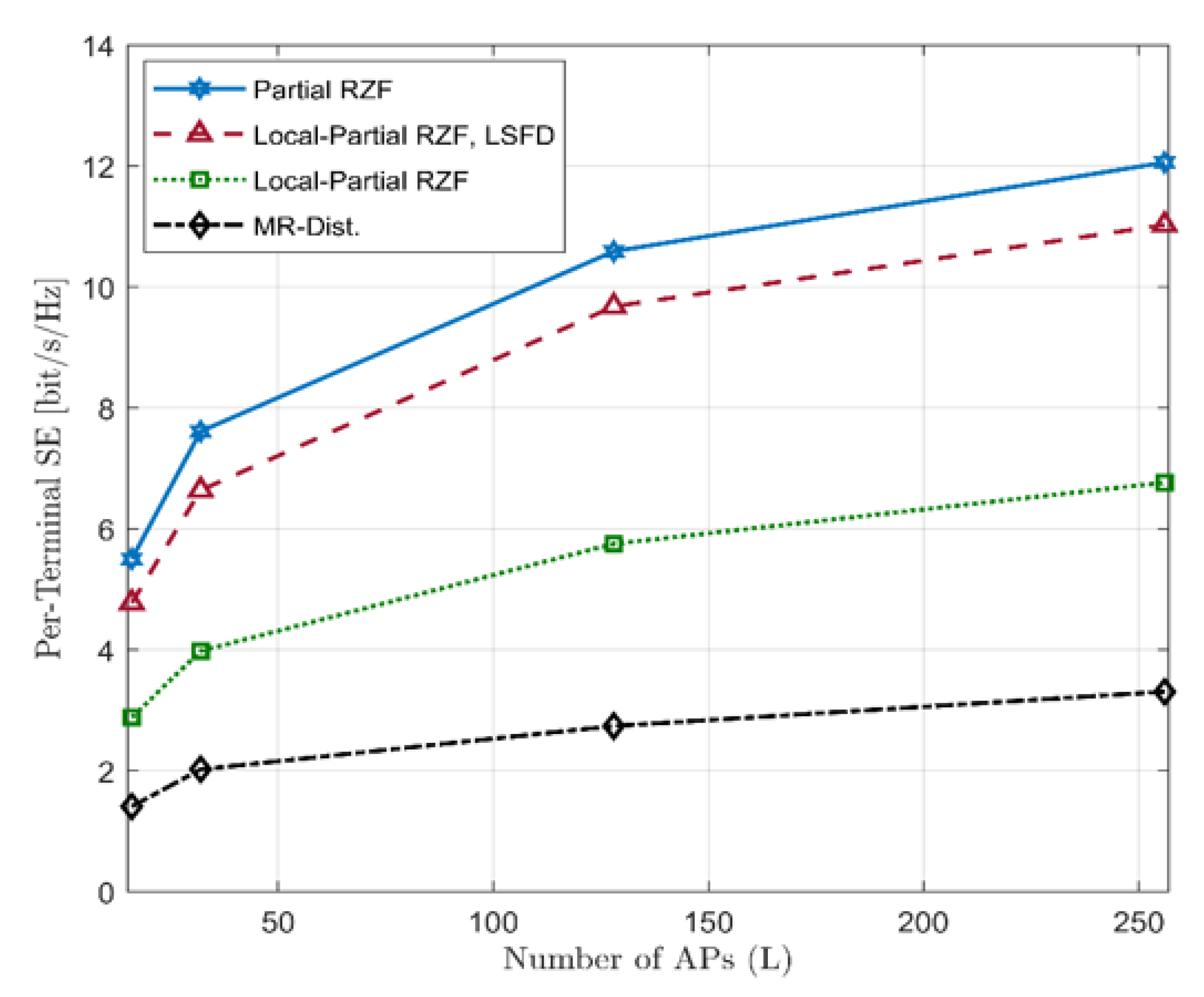
Considering the achievable SE, Figure 6 and Figure 7 depict the average SE of Partial RZF, Local-Partial RZF, and MR as a function of L . We consider K = 8 , L increases with a constant rate, and the number of antennas per APs either one (Figure 6) or four (Figure 7).
As can be seen in Figure 6 and Figure 7, a significant improvement in the achievable SE can be obtained for all schemes when L grows higher. This is due to the increase in diversity gain, which increased with L. Furthermore, one can observe that Partial RZF, Local-Partial RZF, and Local-Partial RZF with LSFD benefit more as compared to the MR when L grows higher. This is because of the ability of ZF-based schemes to minimize inter-user interference.
Among different local combining schemes in the distributed approach, Local-Partial RZF with LSFD scheme offers the highest achievable SE. Figure 7 shows that deploying each AP with more than one antenna significantly improves the average achievable SE. The reason is that increasing the number of antennas per AP increases the ability to suppress the different users’ interference; hence, the average achievable SE is increased.

5.3. Computational Complexity

Unlike centralized-based schemes, distributed combining schemes have the ability to reduce the amount of interference caused between users in a distributed manner, which implies that the APs perform the estimation and design the combining vectors locally. Furthermore, the computations of local distributed-based combining schemes have lower complexity than centralized schemes. This is because the matrix inversion in the local distributed-based schemes has a much smaller dimension.
Figure 8 shows the complexity in terms of the number of complex multiplications as a function of UTs. Among all the five schemes, two centralized schemes, namely, Partial MMSE and Partial RZF, have the highest computational complexity. In the case of Partial MMSE using the dynamic cooperative clustering for a centralized scheme, the computational complexity decreases as the number of UTs increases [33]. In addition, the partial MMSE is a scalable combining scheme that can be employed with a slight loss in SE; as a benefit of this, a reduction in complexity is observed in Figure 8. The Partial RZF has achieved less complexity than Partial MMSE. However, as the number of UTs increases, the computational complexity increases, and the gap between the two schemes decreases. The reason is that in the partial RZF, on average, the number of UTs served by the same group of APS increases as K increases.
For the Local-Partial RZF distributed scheme, it can be observed that the computational complexity is independent of the UTs, so it does not grow as K . Despite having the lowest complexity, MR schemes in both implementations (centralized and distributed) are known to be suboptimal schemes due to their neglecting the existing inter-user interference.

5.4. Discussion

Considering that the proposed scheme entails sharing of the computational load between the CPU and the APs, the Local-Partial RZF distributed scheme would be suitable for modern ‘edge computing’, wherein more and more processing is being delegated to the edge devices and being off-loaded from the central processing node (or the cloud) [48]. This may facilitated by a rapid increase in the computational capabilities of the edge nodes and the availability of high-performance mobile, which can be very effectively utilized for fast matrix inversion operations and complex multiplications.
Furthermore, the observation that the computational complexity for LP-RZF is independent of the number of UTs would imply that the APs (serving as the edge node) need not be upgraded and/or re-configured with an increase in the user count.

6. Conclusions

In cell-free large-scale MU-MIMO, it is assumed that all the UTs are being served by all the APs in the same time-frequency resource. The signal processing is then performed and administered by the CPU with unlimited fronthaul capacity. These characteristics make a system more complex, unscalable, and impractical. In order to reduce the load on the fronthaul connections, local distributed detection schemes have been considered in this paper with realistic and practical system considerations. The results demonstrate that for various distributed configurations, Local-Partial RZF provides the highest achieved average SE while the distributed MR offers the lowest performance. Further, the performance of the distributed schemes can be substantially enhanced by deploying LSFD as a second stage of data detection at the CPU. Moreover, in terms of computational complexity, the Local-Partial RZF distributed scheme can achieve less complexity than the centralized schemes since the computational complexity in the Local-Partial RZF is independent of the UTs, so it does not grow as K . The distributed combining scheme can potentially reduce interference from other UTs in a distributed manner.

Author Contributions

Conceptualization, A.A.A. and M.S.; Data curation, M.S.A.; Investigation, A.A.M. and M.S.A.; Methodology, A.A.A., M.S. and A.A.M.; Resources, M.S.A. All authors have read and agreed to the published version of the manuscript.

Funding

This research received no external funding.

Conflicts of Interest

The authors declare no conflict of interest.

References

  1. Björnson, E.; Sanguinetti, L.; Wymeersch, H.; Hoydis, J.; Marzetta, T.L. Massive MIMO is a reality—What is next? Five promising research directions for antenna arrays. Digit. Signal Process. 2019, 94, 3–20. [Google Scholar] [CrossRef]
  2. Shafi, M.; Molisch, A.F.; Smith, P.J.; Haustein, T.; Zhu, P.; De Silva, P.; Tufvesson, F.; Benjebbour, A.; Wunder, G. 5G: A tutorial overview of standards, trials, challenges, deployment, and practice. IEEE J. Sel. Areas Commun. 2017, 35, 1201–1221. [Google Scholar] [CrossRef]
  3. Wang, C.; Bian, J.; Sun, J.; Zhang, W.; Zhang, M. A Survey of 5G Channel Measurements and Models. IEEE Commun. Surv. Tutor. 2018, 20, 3142–3168. [Google Scholar] [CrossRef]
  4. Lin, Z.; Niu, H.; An, K.; Wang, Y.; Zheng, G.; Chatzinotas, S.; Hu, Y. Refracting RIS-Aided Hybrid Satellite-Terrestrial Relay Networks: Joint Beamforming Design and Optimization. IEEE Trans. Aerosp. Electron. Syst. 2022, 58, 3717–3724. [Google Scholar] [CrossRef]
  5. Da Silva, M.M.; Guerreiro, J. On the 5G and Beyond. Appl. Sci. 2020, 10, 7091. [Google Scholar] [CrossRef]
  6. Lin, Z.; An, K.; Niu, H.; Hu, Y.; Chatzinotas, S.; Zheng, G.; Wang, J. SLNR-based Secure Energy Efficient Beamforming in Multibeam Satellite Systems. IEEE Trans. Aerosp. Electron. Syst. 2022, 1–4. [Google Scholar] [CrossRef]
  7. Rappaport, T.S.; Sun, S.; Mayzus, R.; Zhao, H.; Azar, Y.; Wang, K.; Wong, G.N.; Schulz, J.K.; Samimi, M.; Gutierrez, F. Millimeter Wave Mobile Communications for 5G Cellular: It Will Work! IEEE Access 2013, 1, 335–349. [Google Scholar] [CrossRef]
  8. Han, S.; Chih-Lin, I.; Xu, Z.; Rowell, C. Large-scale antenna systems with hybrid analog and digital beamforming for millimeter wave 5G. IEEE Commun. Mag. 2015, 53, 186–194. [Google Scholar] [CrossRef]
  9. Lin, Z.; Lin, M.; Wang, J.-B.; de Cola, T.; Wang, J. Joint Beamforming and Power Allocation for Satellite-Terrestrial Integrated Networks With Non-Orthogonal Multiple Access. IEEE J. Sel. Top. Signal Process. 2019, 13, 657–670. [Google Scholar] [CrossRef]
  10. Dai, L.; Wang, B.; Yuan, Y.; Han, S.; Chih-Lin, I.; Wang, Z. Non-orthogonal multiple access for 5G: Solutions challenges opportunities and future research trends. IEEE Commun. Mag. 2015, 53, 74–81. [Google Scholar] [CrossRef]
  11. Lin, Z.; Lin, M.; de Cola, T.; Wang, J.-B.; Zhu, W.-P.; Cheng, J. Supporting IoT with Rate-Splitting Multiple Access in Satellite and Aerial-Integrated Networks. IEEE Internet Things J. 2021, 8, 11123–11134. [Google Scholar] [CrossRef]
  12. Marzetta, T.L. Noncooperative Cellular Wireless with Unlimited Numbers of Base Station Antennas. IEEE Trans. Wirel. Commun. 2010, 9, 3590–3600. [Google Scholar] [CrossRef]
  13. Rusek, F.; Persson, D.; Lau, B.K.; Larsson, E.G.; Marzetta, T.L.; Tufvesson, F. Scaling up MIMO: Opportunities and Challenges with Very Large Arrays. IEEE Signal Process. Mag. 2013, 30, 40–60. [Google Scholar] [CrossRef]
  14. Ngo, H.Q.; Larsson, E.G.; Marzetta, T.L. Energy and Spectral Efficiency of Very Large Multiuser MIMO Systems. IEEE Trans. Commun. 2013, 61, 1436–1449. [Google Scholar]
  15. Larsson, E.G.; Edfors, O.; Tufvesson, F.; Marzetta, T.L. Massive MIMO for next-generation wireless systems. IEEE Commun. Mag. 2014, 52, 186–195. [Google Scholar] [CrossRef]
  16. Hoydis, J.; ten Brink, S.; Debbah, M. Massive MIMO in the UL/DL of cellular networks: How many antennas do we need? IEEE J. Sel. Areas Commun. 2013, 31, 160–171. [Google Scholar] [CrossRef]
  17. Björnson, E.; Hoydis, J.; Sanguinetti, L. Massive MIMO Networks: Spectral, Energy, and Hardware Efficiency. Found. Trends Signal Process. 2017, 11, 154–655. [Google Scholar] [CrossRef]
  18. Alammari, A.A.; Sharique, M. Spatial channel correlation for local scattering with linear MMSE-based estimator and detector in multi-cell large scale MU-MIMO networks. Trans. Emerg. Telecommun. Technol. 2021, 32, e4366. [Google Scholar] [CrossRef]
  19. Irmer, R.; Droste, H.; Marsch, P.; Grieger, M.; Fettweis, G.; Brueck, S.; Mayer, H.-P.; Thiele, L.; Jungnickel, V. Coordinated multipoint: Concepts performance and field trial results. IEEE Commun. Mag. 2011, 49, 102–111. [Google Scholar] [CrossRef]
  20. Wang, D.; Wang, J.; You, X.; Wang, Y.; Chen, M.; Hou, X. Spectral efficiency of distributed MIMO systems. IEEE J. Sel. Areas Commun. 2013, 31, 2112–2127. [Google Scholar] [CrossRef]
  21. Kamga, G.N.; Xia, M.; Assa, S. Spectral-efficiency analysis of massive MIMO systems in centralized and distributed schemes. IEEE Trans. Commun. 2016, 64, 1930–1941. [Google Scholar] [CrossRef] [Green Version]
  22. Ngo, H.Q.; Ashikhmin, A.; Yang, H.; Larsson, E.G.; Marzetta, T.L. Cell-free massive MIMO versus small cells. IEEE Trans. Wireless Commun. 2017, 16, 1834–1850. [Google Scholar] [CrossRef]
  23. Liu, W.; Han, S.; Yang, C.; Sun, C. Massive MIMO or small cell network: Who is more energy efficient? In Proceedings of the IEEE Wireless Communications and Networking Conference Workshops (WCNCW), Shanghai, China, 7–10 April 2013; pp. 24–29. [Google Scholar]
  24. Buzzi, S.; D’Andrea, C.; D’Elia, C. User-Centric Cell-Free Massive MIMO with Interference Cancellation and Local ZF Downlink Precoding. In Proceedings of the 2018 15th International Symposium on Wireless Communication Systems (ISWCS), Lisbon, Portugal, 28–31 August 2018; pp. 1–5. [Google Scholar]
  25. Alammari, A.A.; Sharique, M.; Moinuddin, A.A. User-Centric Cell-Free and Co-Located Cellular Large Scale MU-MIMO Systems: A Comparative Performance Study With Spatial Channel Correlation in Dense Urban Scenario. IEEE Access 2022, 10, 48792–48809. [Google Scholar] [CrossRef]
  26. Björnson, E.; Sanguinetti, L. Making Cell-Free Massive MIMO Competitive With MMSE Processing and Centralized Implementation. IEEE Trans. Wirel. Commun. 2020, 19, 77–90. [Google Scholar] [CrossRef]
  27. Interdonato, G.; Björnson, E.; Ngo, H.Q.; Frenger, P.; Larsson, E.G. Ubiquitous cell-free massive MIMO communications. EURASIP J. Wireless Commun. Netw. 2019, 197, 2019. [Google Scholar] [CrossRef]
  28. Chen, Z.; Björnson, E. Channel Hardening and Favorable Propagation in Cell-Free Massive MIMO With Stochastic Geometry. IEEE Trans. Commun. 2018, 66, 5205–5219. [Google Scholar] [CrossRef]
  29. Nayebi, E.; Ashikhmin, A.; Marzetta, T.L.; Yang, H. Cell-free massive MIMO systems. In Proceedings of the 49th Asilomar Conference on Signals, Systems and Computers, Pacific Grove, CA, USA, 8–11 November 2015; pp. 695–699. [Google Scholar]
  30. Nayebi, E.; Ashikhmin, A.; Marzetta, T.L.; Yang, H.; Rao, B.D. Precoding and Power Optimization in Cell-Free Massive MIMO Systems. IEEE Trans. Wirel. Commun. 2017, 16, 4445–4459. [Google Scholar] [CrossRef]
  31. Bashar, M.; Cumanan, K.; Burr, A.G.; Debbah, M.; Ngo, H.Q. Enhanced max-min SINR for uplink cell-free massive MIMO systems. In Proceedings of the 2018 IEEE International Conference on Communications (ICC), Kansas City, MO, USA, 20–24 May 2018; pp. 1–7. [Google Scholar]
  32. Bashar, M.; Cumanan, K.; Burr, A.G.; Ngo, H.Q.; Debbah, M. Cell-free massive MIMO with limited backhaul. In Proceedings of the 2018 IEEE International Conference on Communications (ICC), Kansas City, MO, USA, 20–24 May 2018. [Google Scholar]
  33. Demir, Ö.T.; Björnson, E.; Sanguinetti, L. Foundations of user-centric cell-free massive MIMO. Found. Trends Signal Process. 2021, 14, 162–472. [Google Scholar] [CrossRef]
  34. Papazafeiropoulos, A.; Kourtessis, P.; Renzo, M.D.; Chatzinotas, S.; Senior, J.M. Performance analysis of cell-free massive MIMO systems: A stochastic geometry approach. IEEE Trans. Veh. Technol. 2020, 69, 3523–3537. [Google Scholar] [CrossRef]
  35. Bashar, M.; Ngo, H.Q.; Cumanan, K.; Burr, A.G.; Xiao, P.; Björnson, E.; Larsson, E.G. Uplink Spectral and Energy Efficiency of Cell-Free Massive MIMO With Optimal Uniform Quantization. IEEE Trans. Commun. 2021, 69, 223–245. [Google Scholar] [CrossRef]
  36. Nguyen, T.H.; Nguyen, T.K.; Han, H.D.; Nguyen, V.D. Optimal Power Control and Load Balancing for Uplink Cell-Free Multi-User Massive MIMO. IEEE Access 2018, 6, 14462–14473. [Google Scholar] [CrossRef]
  37. Shaik, Z.H.; Björnson, E.; Larsson, E.G. MMSE-Optimal Sequential Processing for Cell-Free Massive MIMO with Radio Stripes. IEEE Trans. Commun. 2021, 69, 7775–7789. [Google Scholar] [CrossRef]
  38. Zhang, J.; Zhang, J.; Ng, D.W.K.; Jin, S.; Ai, B. Improving Sum-Rate of Cell-Free Massive MIMO With Expanded Compute-and-Forward. IEEE Trans. Signal Process. 2022, 70, 202–215. [Google Scholar] [CrossRef]
  39. Liu, P.; Luo, K.; Chen, D.; Jiang, T. Spectral efficiency analysis of cell-free massive MIMO systems with zero-forcing detector. IEEE Trans. Wireless Commun. 2020, 19, 795–807. [Google Scholar] [CrossRef]
  40. Buzzi, S.; D’Andrea, C. Cell-Free Massive MIMO: User-Centric Approach. IEEE Wirel. Commun. Lett. 2017, 6, 706–709. [Google Scholar] [CrossRef]
  41. Interdonato, G.; Frenger, P.; Larsson, E.G. Scalability Aspects of Cell-Free Massive MIMO. In Proceedings of the ICC 2019—2019 IEEE International Conference on Communications (ICC), Shanghai, China, 20–24 May 2019; pp. 1–6. [Google Scholar]
  42. Nguyen, L.D.; Duong, T.Q.; Ngo, H.Q.; Tourki, K. Energy efficiency in cell-free massive MIMO with zero-forcing precoding design. IEEE Commun. Lett. 2017, 21, 1871–1874. [Google Scholar] [CrossRef]
  43. Femenias, G.; Riera-Palou, F. Cell-Free Millimeter-Wave Massive MIMO Systems With Limited Fronthaul Capacity. IEEE Access 2019, 7, 44596–44612. [Google Scholar] [CrossRef]
  44. Interdonato, G.; Karlsson, M.; Björnson, E.; Larsson, E.G. Local Partial Zero-Forcing Precoding for Cell-Free Massive MIMO. IEEE Trans. Wirel. Commun. 2020, 19, 4758–4774. [Google Scholar] [CrossRef]
  45. Zhang, J.; Zhang, J.; Björnson, E.; Ai, B. Local partial zero-forcing combining for cell-free massive MIMO systems. IEEE Trans. Commun. 2021, 69, 8459–8472. [Google Scholar] [CrossRef]
  46. Björnson, E.; Larsson, E.G.; Debbah, M. Massive MIMO for Maximal Spectral Efficiency: How Many Users and Pilots Should Be Allocated? IEEE Trans. Wirel. Commun. 2016, 15, 1293–1308. [Google Scholar] [CrossRef]
  47. Jin, S.-N.; Yue, D.-W.; Nguyen, H.H. Spectral and Energy Efficiency in Cell-Free Massive MIMO Systems Over Correlated Rician Fading. IEEE Syst. J. 2021, 15, 2822–2833. [Google Scholar] [CrossRef]
  48. Ansari, M.S.; Alsamhi, S.H.; Qiao, Y.; Ye, Y.; Lee, B. Security of distributed intelligence in edge computing: Threats and countermeasures. In The Cloud-to-Thing Continuum; Palgrave Macmillan: Cham, Switzerland, 2020; pp. 95–122. [Google Scholar]
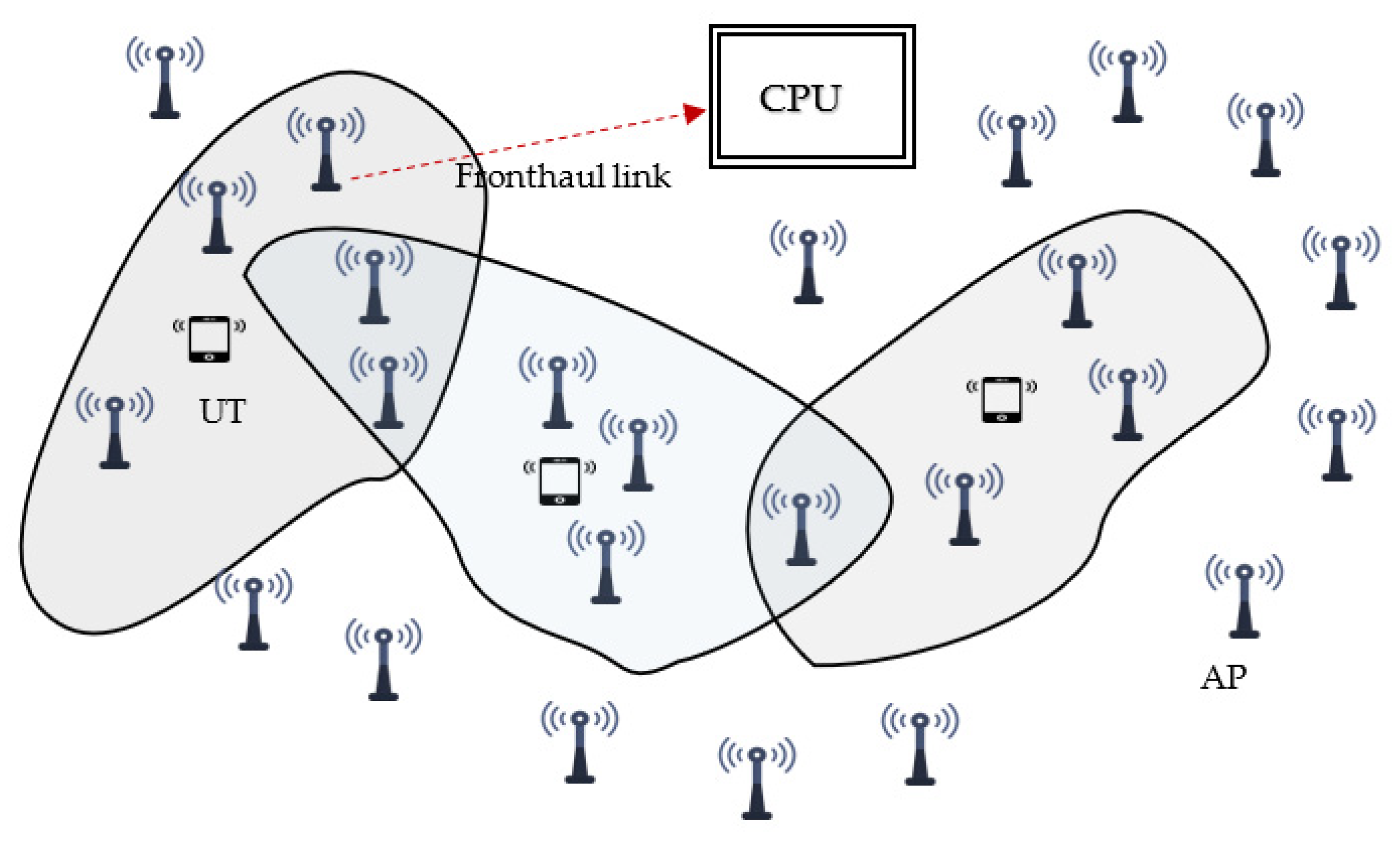
Figure 1. User-Centric Cell-Free system with dynamic cooperative clustering.
Electronics 11 02757 g001
Figure 2. Local Distributed Operations considered in this work.
Electronics 11 02757 g002
Figure 3. Three-dimensional physical channel model, where the scatterers are distributed around the user terminal (UT). Each path is characterized by two angles: the azimuth ( φ i ) and elevation ( θ i ).
Electronics 11 02757 g003
Figure 4. Cumulative Distribution Function (CDF) distribution of for an arbitrary UT as a function of the average achievable SE, with L = 256, K = 32, and τp = 8.
Electronics 11 02757 g004
Figure 5. Average achieved SE as a function of pilot scaling factor, with K = 128, L = 1024, and τ 0   = 8.
Electronics 11 02757 g005
Figure 6. Average achievable SE as a function of L, with K = 8, and τ 0 = 8 . Each AP is equipped by a single antenna.
Electronics 11 02757 g006
Figure 7. Average achievable SE as a function of L, with K = 8, and τ 0 = 8 . Each AP is equipped by four antennas.
Electronics 11 02757 g007
Figure 8. The number of computational complexities as a function of UTs. The total number of ASs in the network L = 100, and each AP is equipped with 4 antennas. We consider τ0 = 8.
Electronics 11 02757 g008
Publisher’s Note: MDPI stays neutral with regard to jurisdictional claims in published maps and institutional affiliations.