

Large-Signal Stabilization Method for Islanded DC Microgrids Considering Battery and Supercapacitor Hybrid Energy Storage Systems

Abstract
:1. Introduction
- (1)
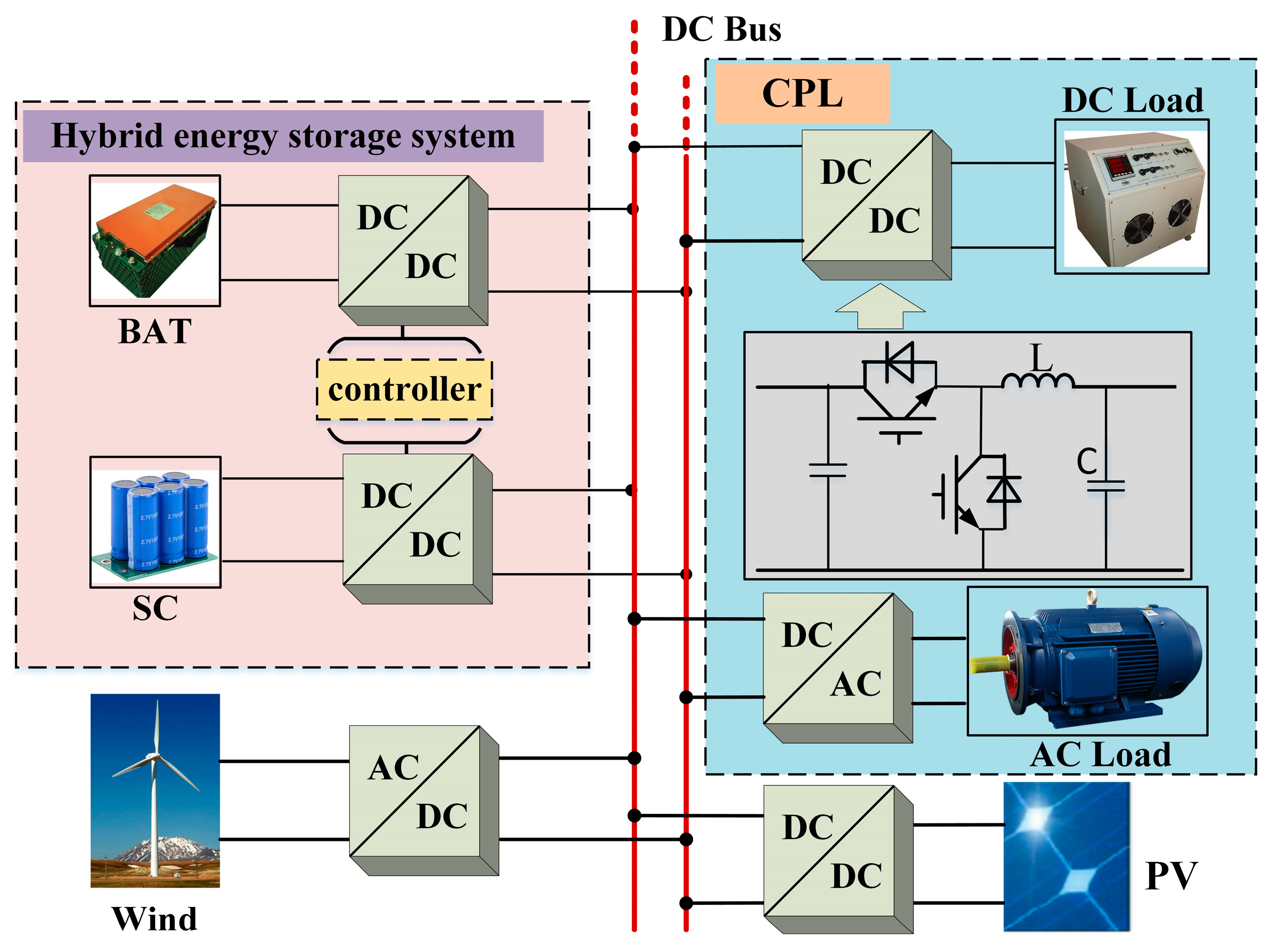
- The topological structure of and control strategy for islanded DC microgrids containing CPLs, DGs and an HESS are proposed. A nonlinear model of the system is obtained. Based on the mixed potential function theory, a large-signal model and a large-signal stability criterion for DC microgrids are obtained;
- (2)
- The presented large-signal stability criterion reveals the relationships among the filtering parameters, DG power, CPL power, the proportional control parameter (kip1) of the inner current loop for the battery converter, the proportional control parameter (kvp2) of the outer power loop for the SC converter and the stability of the islanded DC microgrids. Moreover, simultaneously, important large-signal stabilization design methods for the HESS converter’s control parameters for DC microgrids are provided;
- (3)
- Regulating the proportional control parameter (kip1) of the inner current loop for the battery converter and the proportional control parameter (kvp2) of the outer power loop for the SC converter can optimize a control strategy for islanded DC microgrids and enhance system stability without extra equipment.
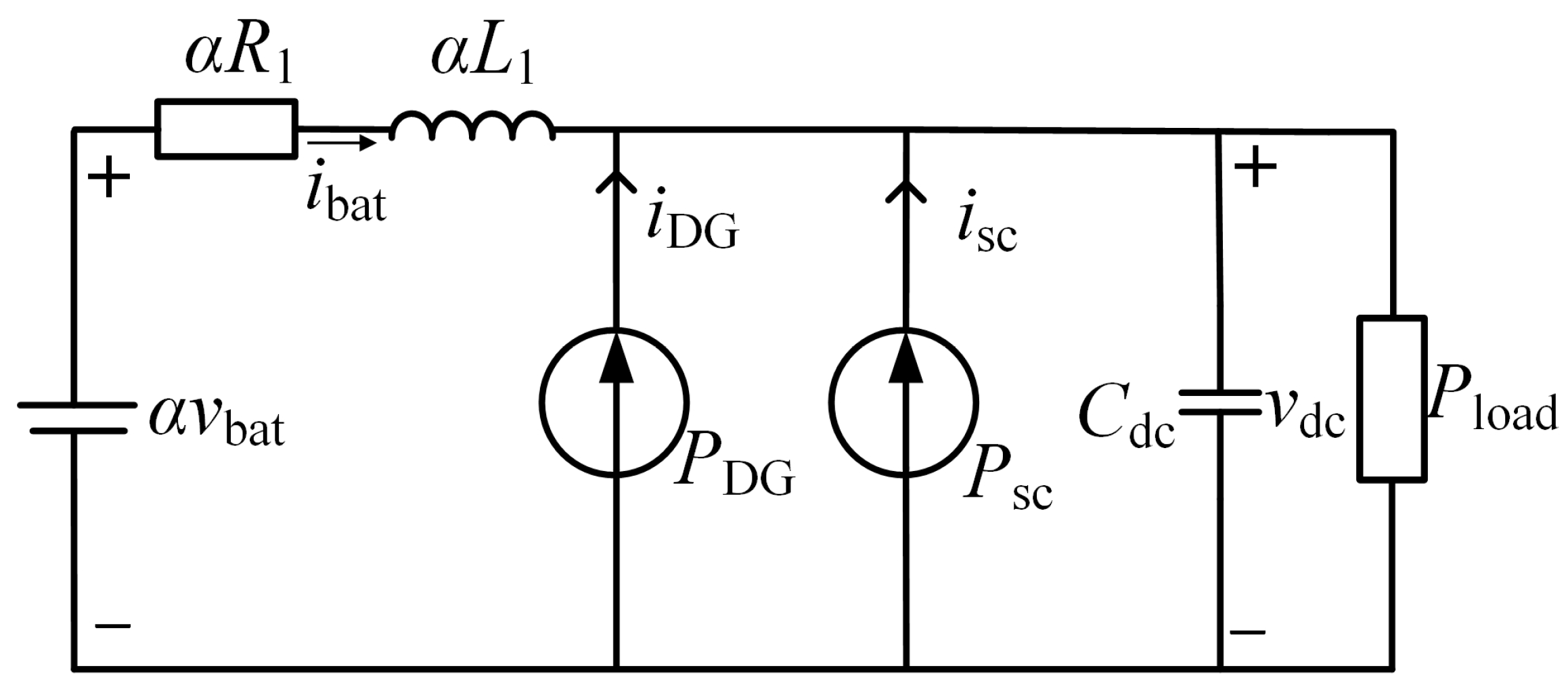
2. Modeling of and Control Strategy for DC Microgrids
2.1. Modeling
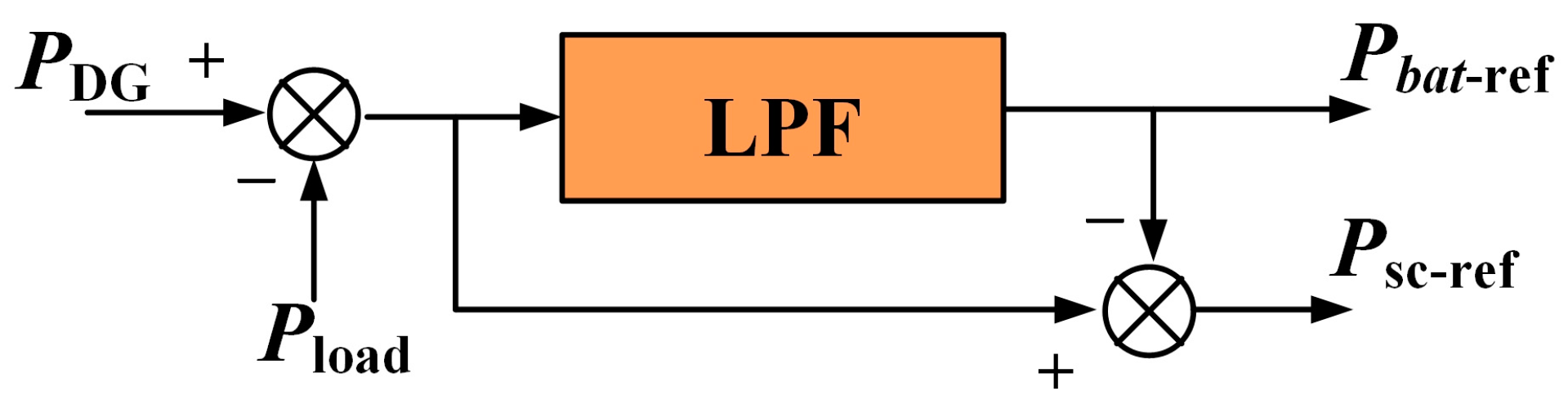
2.2. Control Strategy
3. Large-Signal Stabilization Method
- (1)
- The potential function of non-energy storage components in the system is obtained;
- (2)
- The energy absorbed by the capacitor element in the system is calculated;
- (3)
- The formulas obtained are written in standard form.
Large-Signal Stabilization Method for DC Microgrids with HESS
4. Large-Signal Stabilizations Method
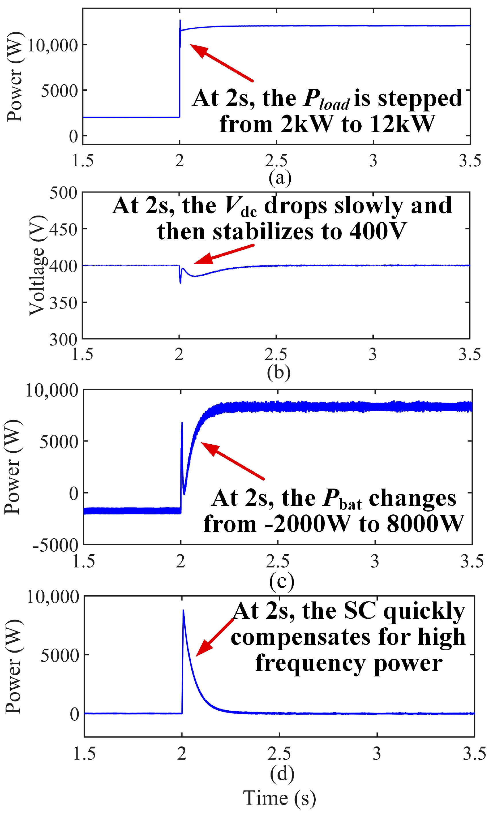
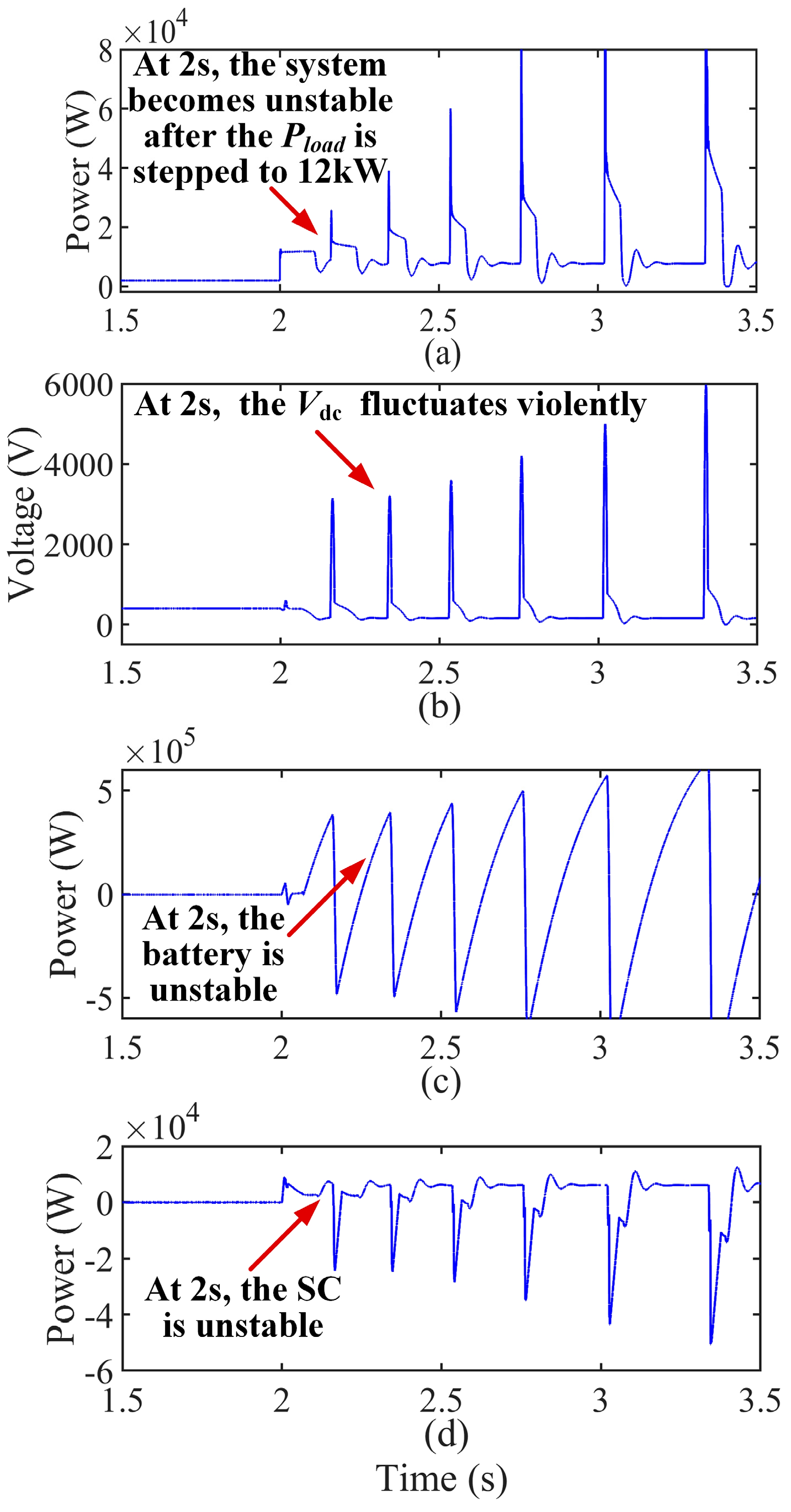
5. Experimental Results
6. Conclusions
Author Contributions
Funding
Conflicts of Interest
References
- Liang, D.; Qin, C.; Wang, S.; Guo, H. Reliability evaluation of DC distribution power network. In Proceedings of the 2018 China International Conference on Electricity Distribution (CICED), Tianjin, China, 17–19 September 2018; pp. 654–659. [Google Scholar]
- Zhang, Q.J.; Zeng, Y.J.; Liu, Y.C.; Zhuang, X.Z.; Zhang, H.W.; Hu, W.B.; Guo, H.H. An Improved Distributed Cooperative Control Strategy for Multiple Energy Storages Parallel in Islanded DC Microgrid. IEEE J. Emerg. Sel. Top. Power Electron. 2022, 10, 455–468. [Google Scholar] [CrossRef]
- Haruni, A.M.O.; Negnevitsky, M.; Haque, E.; Gargoom, A. A Novel Operation and Control Strategy for a Standalone Hybrid Renewable Power System. IEEE Trans. Sustain. Energy 2013, 4, 402–413. [Google Scholar] [CrossRef]
- Chen, X.; Shi, M.; Zhou, J.; Chen, Y.; Zuo, W.; Wen, J.; He, H. Distributed Cooperative Control of Multiple Hybrid Energy Storage Systems in a DC Microgrid Using Consensus Protocol. IEEE Trans. Ind. Electron. 2020, 67, 1968–1979. [Google Scholar] [CrossRef]
- Thang, T.V.; Ahmed, A.; Kim, C.-I.; Park, J.-H. Flexible System Architecture of Stand-Alone PV Power Generation with Energy Storage Device. IEEE Trans. Energy Convers. 2015, 30, 1386–1396. [Google Scholar] [CrossRef]
- Tin, B.; Sandor, I.; Damir, S. Model predictive direct current control of a permanent magnet synchronous generator based on flexible Lyapunov function considering converter dead time. IEEE Trans. Ind. Appl. 2018, 54, 2899–2912. [Google Scholar]
- Tahim, A.P.N.; Pagano, D.J.; Lenz, E.; Stramosk, V. Modeling and Stability Analysis of Islanded DC Microgrids Under Droop Control. IEEE Trans. Power Electron. 2015, 30, 4597–4607. [Google Scholar] [CrossRef]
- Chen, S.; Yang, Q.; Zhou, J.; Chen, X. A model predictive control method for hybrid energy storage systems. CSEE J. Power Energy Syst. 2021, 7, 329–338. [Google Scholar]
- Peng, Q.; Yuan, Z.; Ouyang, B.; Guo, P.; Qu, L. Research on the Optimal Operation Method of DC Microgrid Base on the New DC Power Distribution Management System. Electronics 2019, 9, 9. [Google Scholar] [CrossRef]
- Pirooz, A.; Noroozian, R. Model predictive control of classic bidirectional dc-dc converter for battery applications. In Proceedings of the 2016 7th Power Electronics and Drive Systems Technologies Conference (PEDSTC), Tehran, Iran, 16–18 February 2016; pp. 517–522. [Google Scholar]
- Khomenko, M.; Veligorskyi, O.; Husev, O.; Tytelmaier, K.; Yershov, R. Model predictive control of photovoltaic bidirectional DC-DC converter with coupled inductors. In Proceedings of the 2017 IEEE First Ukraine Conference on Electrical and Computer Engineering (UKRCON), Kyiv, Ukraine, 29 May–2 June 2017; pp. 578–583. [Google Scholar]
- Xiao, J.; Wang, P.; Setyawan, L. Multilevel Energy Management System for Hybridization of Energy Storages in DC Microgrids. IEEE Trans. Smart Grid 2016, 7, 847–856. [Google Scholar] [CrossRef]
- Lin, P.; Zhao, T.; Wang, B.; Wang, Y.; Wang, P. A Semi-Consensus Strategy Toward Multi-Functional Hybrid Energy Storage System in DC Microgrids. IEEE Trans. Energy Convers. 2020, 35, 336–346. [Google Scholar] [CrossRef]
- Oliveira, T.R.; Silva, W.W.A.G.; Donoso-Garcia, P.F. Distributed Secondary Level Control for Energy Storage Management in DC Microgrids. IEEE Trans. Smart Grid 2017, 8, 2597–2607. [Google Scholar] [CrossRef]
- Zhang, M.; Xu, Q.; Zhang, C.; Nordström, L.; Blaabjerg, F. Decentralized Coordination and Stabilization of Hybrid Energy Storage Systems in DC Microgrids. IEEE Trans. Smart Grid 2022, 13, 1751–1761. [Google Scholar] [CrossRef]
- Ramos, G.A.; Costa-Castelló, R. Energy Management Strategies for Hybrid Energy Storage Systems Based on Filter Control: Analysis and Comparison. Electronics 2022, 11, 1631. [Google Scholar] [CrossRef]
- Feng, L.; Zhang, J.; Li, G.; Zhang, B. Cost reduction of a hybrid energy storage system considering correlation between wind and PV power. Prot. Control Mod. Power Syst. 2016, 1, 11. [Google Scholar] [CrossRef]
- Yang, F.; Xue, H.; Wang, Y.F. Research on Control Strategy of Supercapacitors Energy Storage System. Adv. Mater. Res. 2011, 347–353, 3881–3885. [Google Scholar] [CrossRef]
- Du, W.; Zhang, J.; Zhang, Y.; Qian, Z. Stability Criterion for Cascaded System With Constant Power Load. IEEE Trans. Power Electron. 2013, 28, 1843–1851. [Google Scholar] [CrossRef]
- Cespedes, M.; Xing, L.; Sun, J. Constant-Power Load System Stabilization by Passive Damping. IEEE Trans. Power Electron. 2011, 26, 1832–1836. [Google Scholar] [CrossRef]
- Rahimi, A.M.; Emadi, A. Active Damping in DC/DC Power Electronic Converters: A Novel Method to Overcome the Problems of Constant Power Loads. IEEE Trans. Ind. Electron. 2009, 56, 1428–1439. [Google Scholar] [CrossRef]
- Magne, P.; Marx, D.; Nahid-Mobarakeh, B.; Pierfederici, S. Large-Signal Stabilization of a DC-Link Supplying a Constant Power Load Using a Virtual Capacitor: Impact on the Domain of Attraction. IEEE Trans. Ind. Appl. 2012, 48, 878–887. [Google Scholar] [CrossRef]
- Zhang, X.; Ruan, X.; Zhong, Q.C. Improving the stability of cascaded DC/DC converter systems via shaping the input impedance of the load converter with a parallel or series virtual impedance. IEEE Trans. Ind. Electron. 2015, 62, 7499–7512. [Google Scholar] [CrossRef]
- Zhao, Y.; Qiao, W.; Ha, D. A sliding-mode duty-ratio controller for dc/dc buck converters with constant power loads. IEEE Trans. Ind. Appl. 2014, 50, 1448–1458. [Google Scholar] [CrossRef]
- Xu, Q.; Zhang, C.; Wen, C.; Wang, P. A Novel Composite Nonlinear Controller for Stabilization of Constant Power Load in DC Microgrid. IEEE Trans. Smart Grid 2019, 10, 752–761. [Google Scholar] [CrossRef]
- Gui, Y.; Han, R.; Guerrero, J.M.; Vasquez, J.C.; Wei, B.; Kim, W. Large-Signal Stability Improvement of DC-DC Converters in DC Microgrid. IEEE Trans. Energy Convers. 2021, 36, 2534–2544. [Google Scholar] [CrossRef]
- Vafamand, N.; Yousefizadeh, S.; Khooban, M.H.; Bendtsen, J.D.; Dragicevic, T. Adaptive TS Fuzzy-Based MPC for DC Microgrids With Dynamic CPLs: Nonlinear Power Observer Approach. IEEE Syst. J. 2019, 13, 3203–3210. [Google Scholar] [CrossRef]
- Guo, L.; Feng, Y.B.; Li, X.L. Study on stability analysis and damping control method of DC microgrid. In Proceedings of the 2018 IEEE 2nd International Electrical and Energy Conference (CIEEC), Beijing, China, 4–6 November 2018; Volume 36, pp. 927–936. [Google Scholar]
- Kollimalla, S.K.; Mishra, M.K.; Ukil, A.; Gooi, H.B. DC Grid Voltage Regulation Using New HESS Control Strategy. IEEE Trans. Sustain. Energy 2017, 8, 772–781. [Google Scholar] [CrossRef]
- Zhao, Z.L.; Yang, P.; Zheng, C.L. Review on dynamic stability research of microgrid. Trans. China Electrotech. Soc. 2017, 32, 111–122. [Google Scholar]
- Anand, S.; Fernandes, B.G. Reduced-Order Model and Stability Analysis of Low-Voltage DC Microgrid. IEEE Trans. Ind. Electron. 2013, 60, 5040–5049. [Google Scholar] [CrossRef]
- Zekun, L.; Wei, P.; Li, K. Large-disturbance Stability Analysis of DC Microgrid with Constant Power Load and its Transient Voltage Stability Control Strategy. In Proceedings of the 2018 China International Conference on Electricity Distribution (CICED), Tianjin, China, 17–19 September 2018; pp. 1686–1690. [Google Scholar]
- Marx, D.; Magne, P.; Nahid-Mobarakeh, B.; Pierfederici, S.; Davat, B. Large Signal Stability Analysis Tools in DC Power Systems With Constant Power Loads and Variable Power Loads—A Review. IEEE Trans. Power Electron. 2012, 27, 1773–1787. [Google Scholar] [CrossRef]
- Sanchez, S.; Molinas, M. Large Signal Stability Analysis at the Common Coupling Point of a DC Microgrid: A Grid Impedance Estimation Approach Based on a Recursive Method. IEEE Trans. Energy Convers. 2015, 30, 122–131. [Google Scholar] [CrossRef]
- Xie, W.; Han, M.; Cao, W.; Guerrero, J.M.; Vasquez, J.C. System-Level Large-Signal Stability Analysis of Droop-Controlled DC Microgrids. IEEE Trans. Power Electron. 2021, 36, 4224–4236. [Google Scholar] [CrossRef]
- Du, W.J.; Zhang, J.M.; Qian, Z.M. Compensation methodology for DC bus voltage of cascaded system formed by Buck converters. Trans. China Electrotech. Soc. 2015, 30, 135–142. [Google Scholar]
- Hassan, M.A.; Li, E.-p.; Li, X.; Li, T.; Duan, C.; Chi, S. Adaptive Passivity-Based Control of DC-DC Buck Power Converter with Constant Power Load in DC Microgrid Systems. IEEE J. Emerg. Sel. Top. Power Electron. 2019, 7, 2029–2040. [Google Scholar] [CrossRef]
- Huang, M.; Ji, H.; Sun, J.; Wei, L.; Zha, X. Bifurcation-Based Stability Analysis of Photovoltaic-Battery Hybrid Power System. IEEE J. Emerg. Sel. Top. Power Electron. 2017, 5, 1055–1067. [Google Scholar] [CrossRef]
- Peng, D.; Huang, M.; Li, J.; Sun, J.; Zha, X.; Wang, C. Large-Signal Stability Criterion for Parallel-Connected DC-DC Converters With Current Source Equivalence. IEEE Trans. Circuits Syst. II Express Briefs 2019, 66, 2037–2041. [Google Scholar] [CrossRef]
- Zhang, Z.; Yang, X.; Zhao, S.; Wu, D.; Cao, J.; Gao, M.; Zeng, G.; Wang, Z. Large-signal stability analysis of islanded DC microgrids with multiple types of loads. Int. J. Electr. Power Energy Syst. 2022, 143, 108450. [Google Scholar] [CrossRef]
- Xie, W.; Han, M.; Cao, W.; Guerrero, J.M.; Vasquez, J.C. Virtual Resistance Tradeoff Design for DCMG Grid-Forming Converters Considering Static- and Large-Signal Dynamic Constraints. IEEE Trans. Power Electron. 2021, 36, 5582–5593. [Google Scholar] [CrossRef]
- Wang, S.; Yu, Y.; Tian, Z.; Zha, X. Energy-based large-signal stability analysis of DC microgrid considering dynamic interactions between multiple converters. In Proceedings of the 2021 IEEE 16th Conference on Industrial Electronics and Applications (ICIEA), Chengdu, China, 1–4 August 2021; pp. 1032–1039. [Google Scholar]
- Zakir, M.; Sher, H.A.; Arshad, A.; Lehtonen, M. A fault detection, localization, and categorization method for PV fed DC-microgrid with power-sharing management among the nano-grids. Int. J. Electr. Power Energy Syst. 2022, 137, 107858. [Google Scholar] [CrossRef]


| Parameter | Value |
|---|---|
| vdc (V) | 400 |
| vb (V) | 150 |
| vsc (V) | 160 |
| vload (V) | 200 |
| Lbat (mH) | 5 |
| Ls (mH) | 20 |
| Cdc (mF) | 3 |
| PCPL (kW) | 2 |
| PDG (kW) | 4 |
| Parameter | A | B |
|---|---|---|
| kip1 | 10 | 2 |
| kvp2 | 0.1 | 0.1 |
| PCPL | 2 kW → 12 kW | |
| Satisfying the proposed large-signal stabilization method | Yes | No |
| Parameter | C | D |
|---|---|---|
| kip1 | 8.0 | |
| kvp2 | 0.1 | |
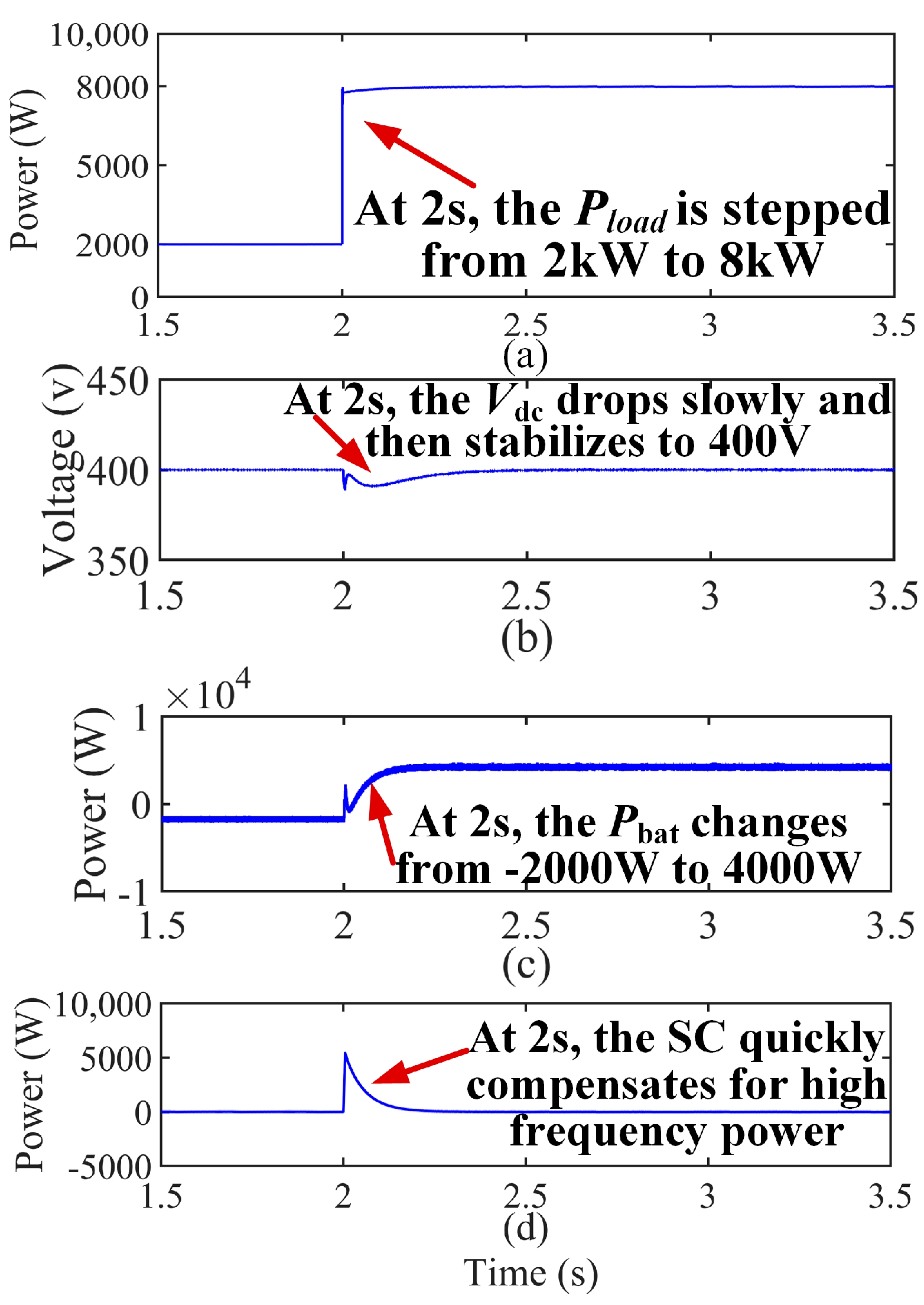
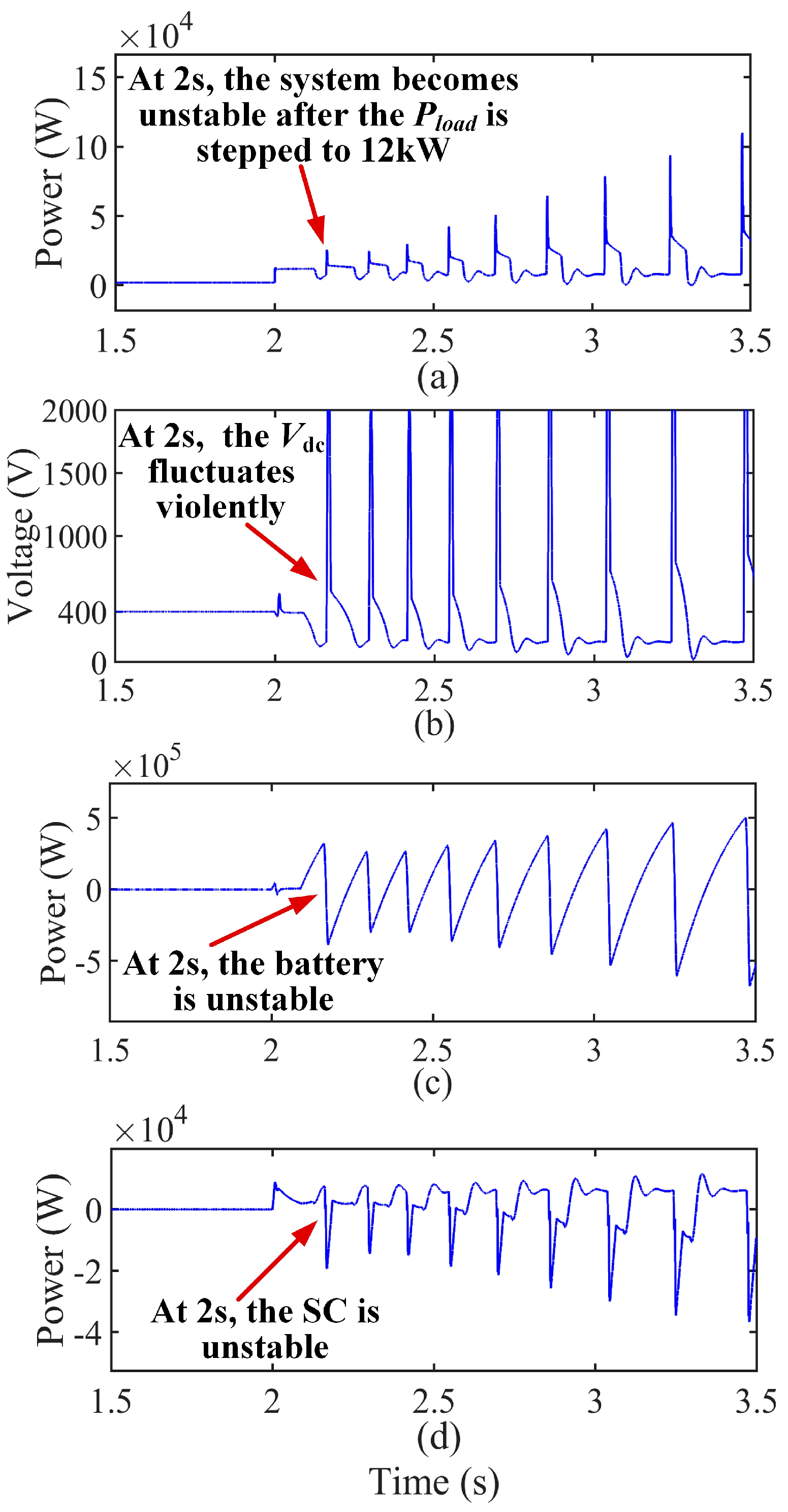
| PCPL | 2 kW → 8 kW | 2 kW → 12 kW |
| Satisfying the proposed large-signal stabilization method | Yes | No |
| Load Resistance (Ω) | Inductance Value (mH) |
|---|---|
| 100 | 1.3 |
| 28.6 | 0.4 |
| 20 | 0.28 |
| Parameter | Value |
|---|---|
| vdc (V) | 60 |
| vb (V) | 36 |
| vsc (V) | 24 |
| vload (V) | 48 |
| L1 (mH) | 2.95 |
| L2 (mH) | 5 |
| L3 (mH) | 5 |
| Cdc (mF) | 2.2 |
| Parameter | E | F |
|---|---|---|
| kip1 | 0.6 | 0.2 |
| kvp2 | 0.1 | 0.1 |
| PCPL | 23 W → 80 W | |
| Satisfying the proposed large-signal stabilization method | Yes | No |
| Parameter | G | H |
|---|---|---|
| kip1 | 0.4 | |
| kvp2 | 0.1 | |
| PCPL | 23 W → 80 W | 23 W → 115 W |
| Satisfying the proposed large-signal stabilization method | Yes | No |
Publisher’s Note: MDPI stays neutral with regard to jurisdictional claims in published maps and institutional affiliations. |
© 2022 by the authors. Licensee MDPI, Basel, Switzerland. This article is an open access article distributed under the terms and conditions of the Creative Commons Attribution (CC BY) license (https://creativecommons.org/licenses/by/4.0/).
Share and Cite
Liu, X.; Suo, Y.; Song, X.; Zhou, J.; Qu, Y. Large-Signal Stabilization Method for Islanded DC Microgrids Considering Battery and Supercapacitor Hybrid Energy Storage Systems. Electronics 2022, 11, 2823. https://doi.org/10.3390/electronics11182823
Liu X, Suo Y, Song X, Zhou J, Qu Y. Large-Signal Stabilization Method for Islanded DC Microgrids Considering Battery and Supercapacitor Hybrid Energy Storage Systems. Electronics. 2022; 11(18):2823. https://doi.org/10.3390/electronics11182823
Chicago/Turabian StyleLiu, Xinbo, Yongbing Suo, Xiaotong Song, Jinghua Zhou, and Yaxin Qu. 2022. "Large-Signal Stabilization Method for Islanded DC Microgrids Considering Battery and Supercapacitor Hybrid Energy Storage Systems" Electronics 11, no. 18: 2823. https://doi.org/10.3390/electronics11182823