
An X-Band Reflective Active Polarization Conversion Metasurface


Abstract
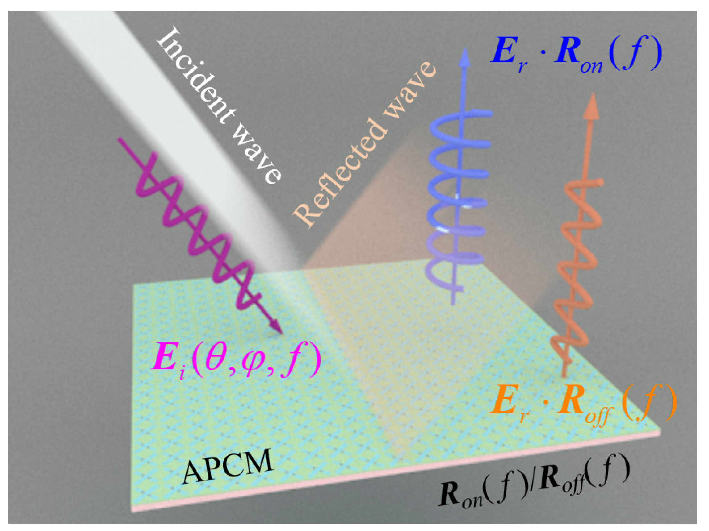
:1. Introduction
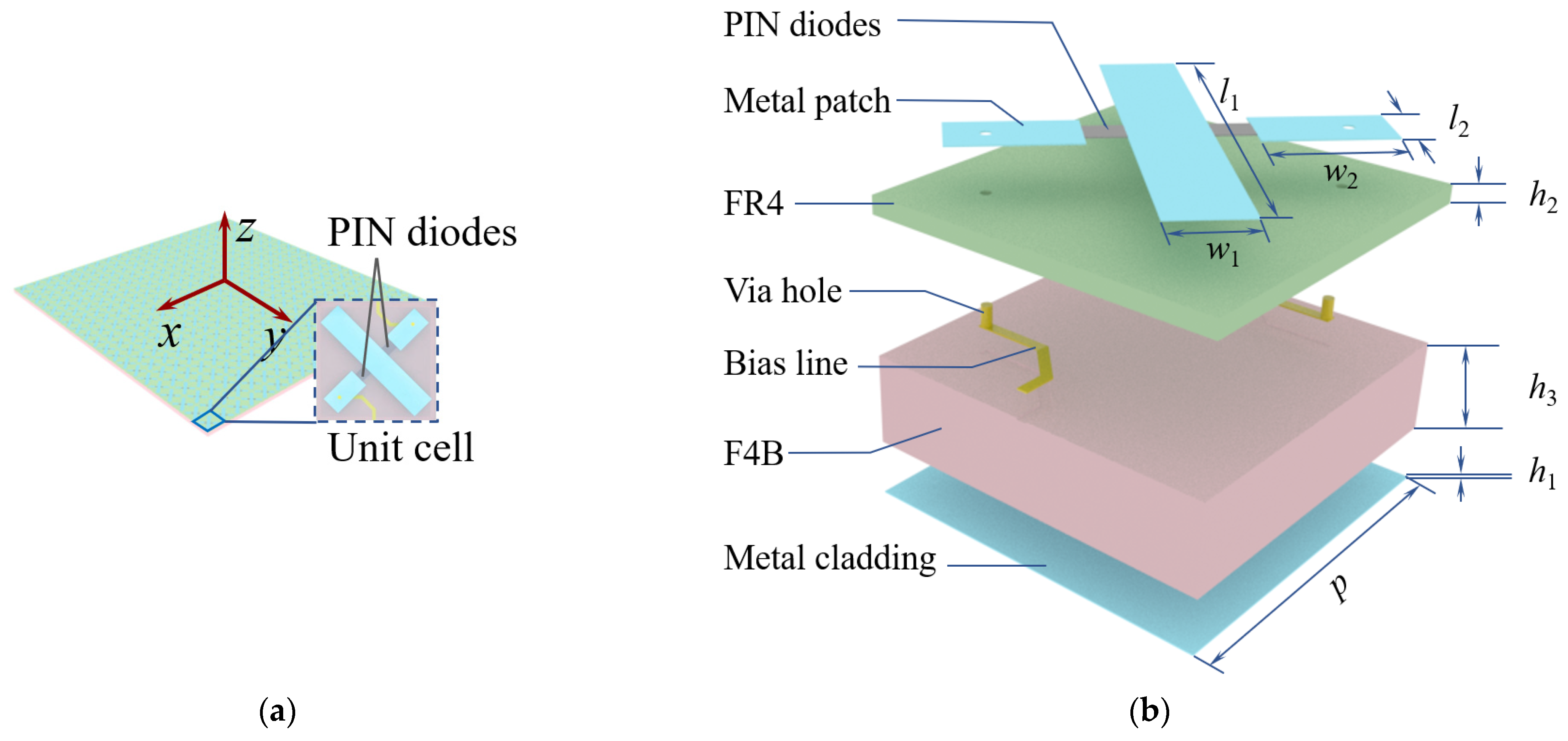
2. Design of APCM
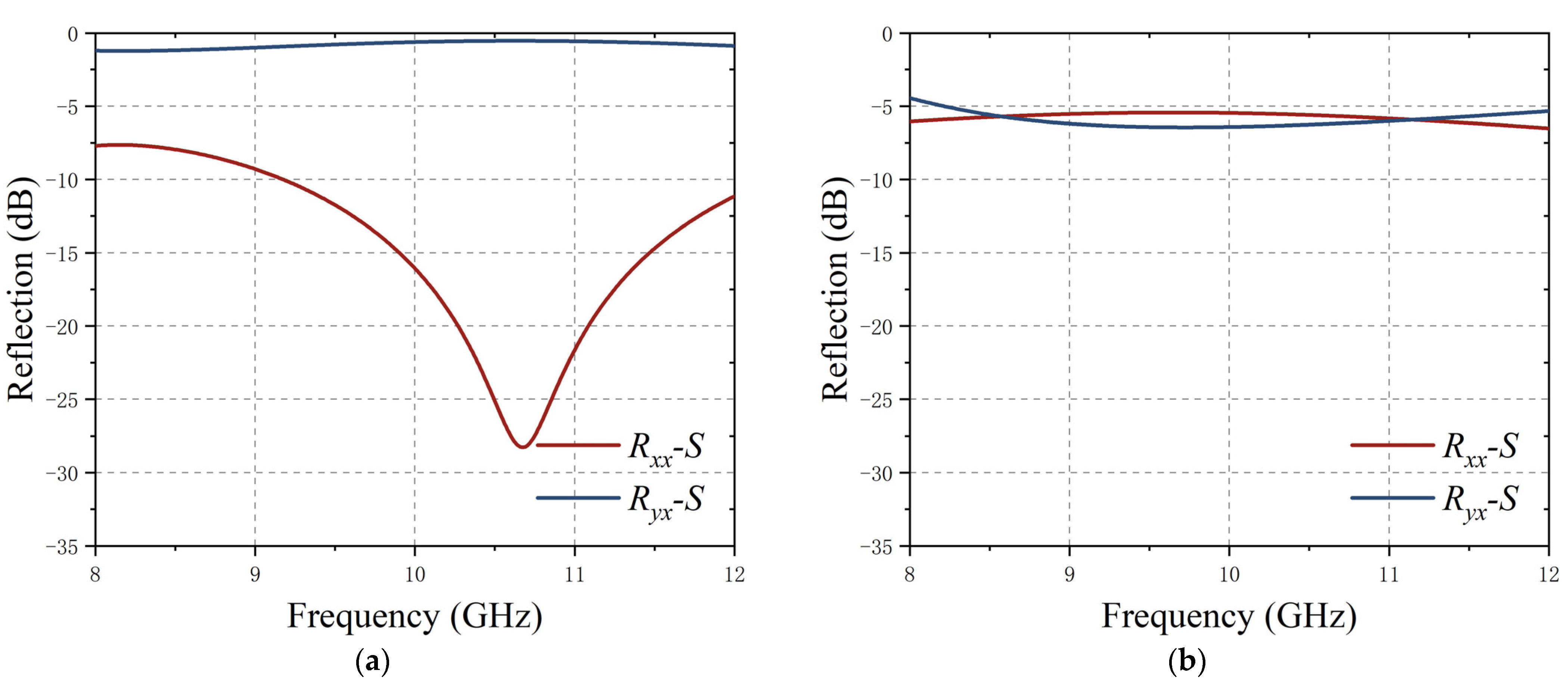
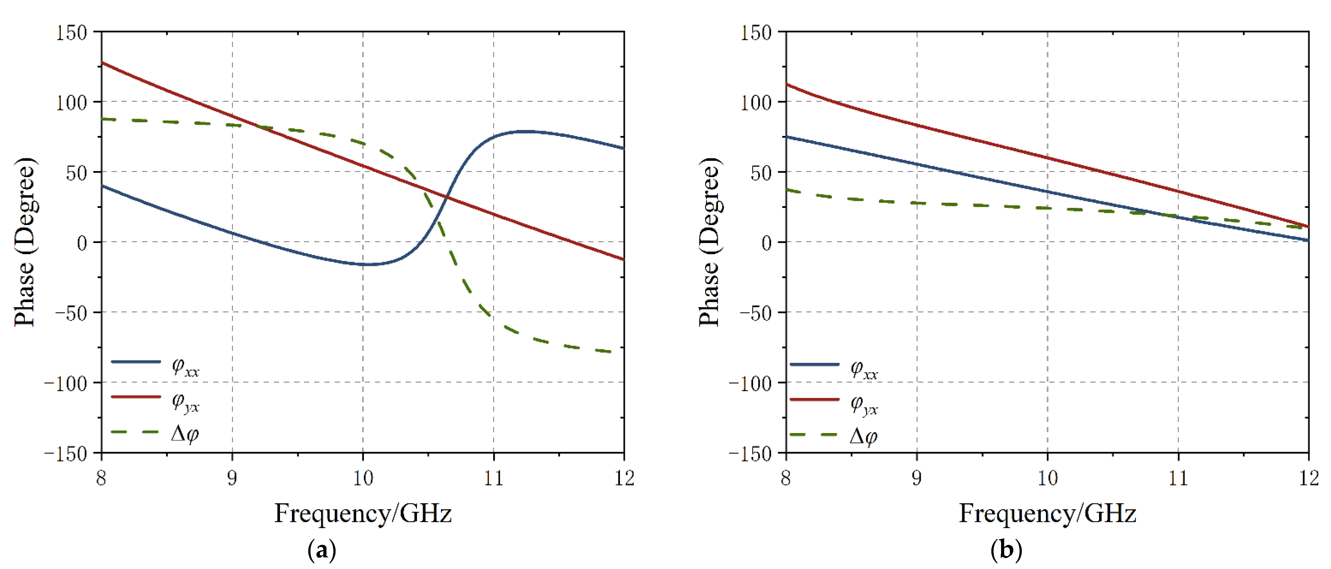
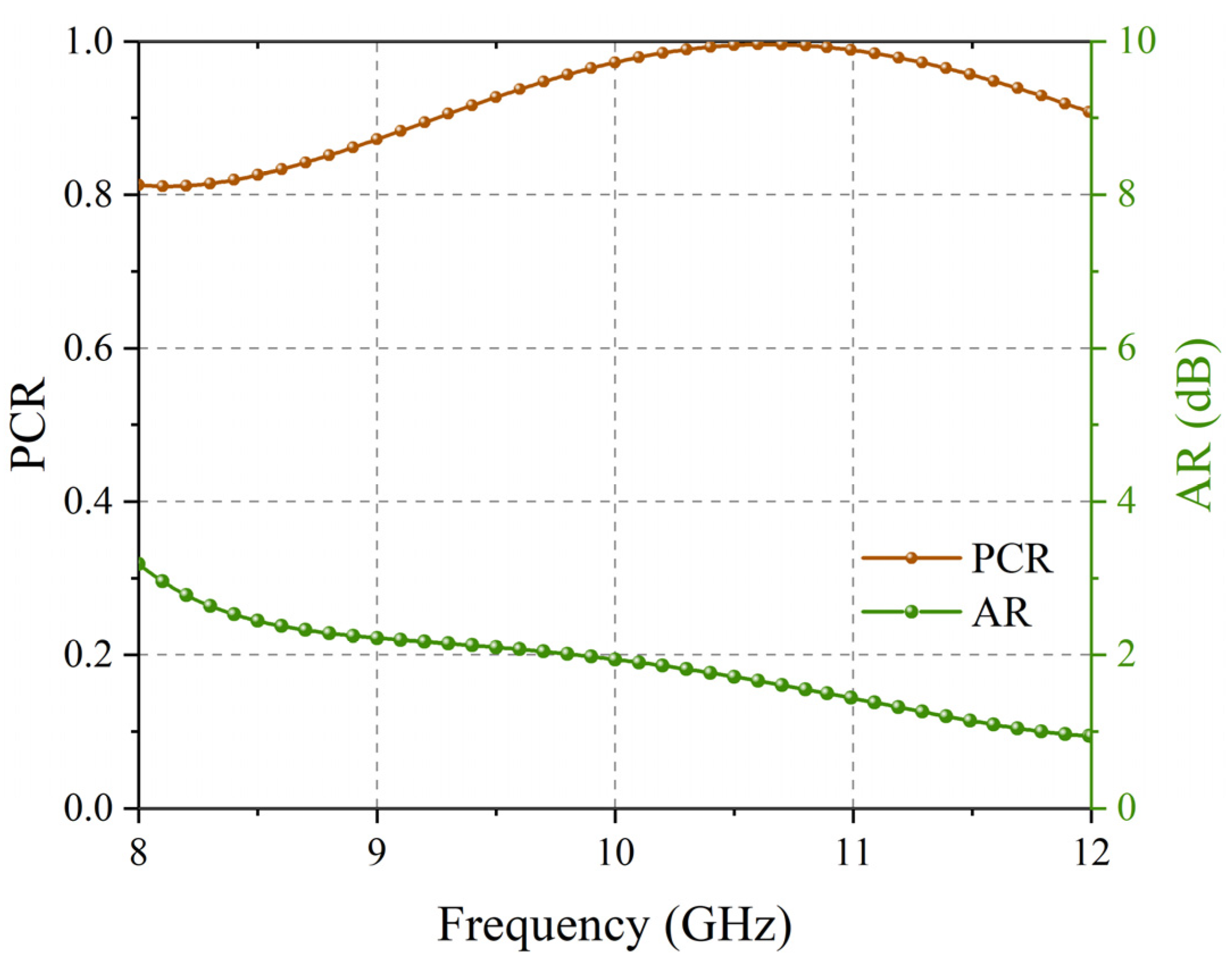
3. Simulation and Analysis
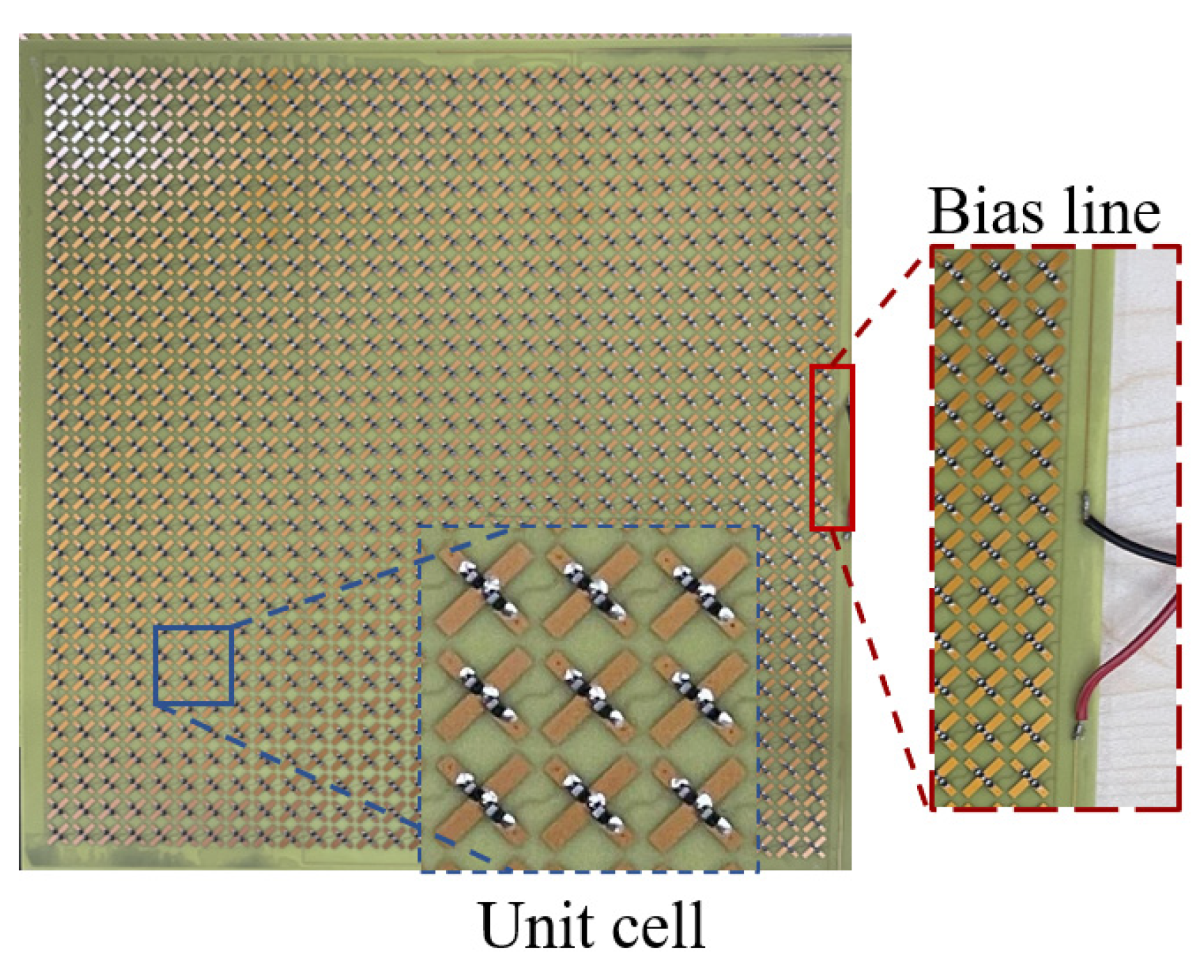
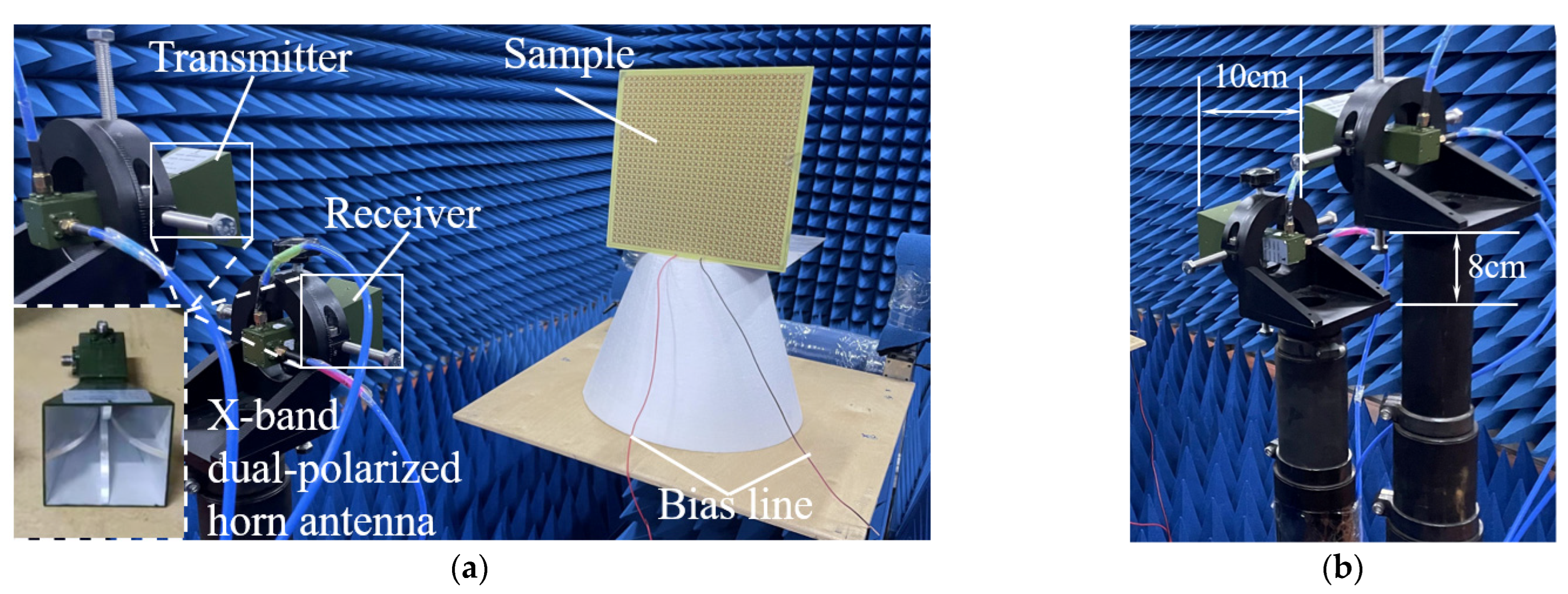
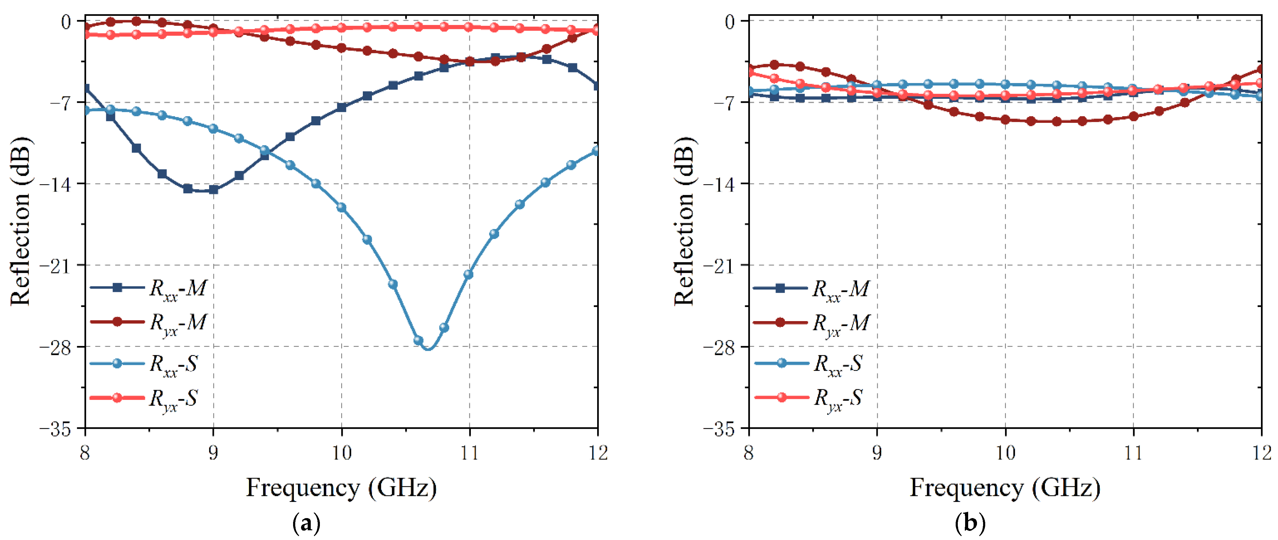
4. Fabrication and Measurement
5. Conclusions
Author Contributions
Funding
Data Availability Statement
Conflicts of Interest
References
- Goldberg, A.Z.; James, D.F.V. Perfect polarization for arbitrary light beams. Phys. Rev. A 2017, 96, 9. [Google Scholar] [CrossRef]
- Yamaguchi, Y.; Sato, A.; Boerner, W.M.; Sato, R.; Yamada, H. Four-Component Scattering Power Decomposition With Rotation of Coherency Matrix. IEEE Trans. Geosci. Remote Sens. 2011, 49, 2251–2258. [Google Scholar] [CrossRef]
- Li, L.; Wang, J.; Feng, M.; Wang, J.; Ma, H.; Chen, H.; Du, H.; Zhang, J.; Qu, S. Frequency selective polarization conversion metasurface using E-shaped high permittivity ceramics. In Proceedings of the IEEE International Workshop on Antenna Technology (iWAT), Nanjing, China, 5–7 March 2018. [Google Scholar]
- Ding, F.; Wang, Z.; He, S.; Shalaev, V.M.; Kildishev, A.V. Broadband high-efficiency half-wave plate: A supercell-based plasmonic metasurface approach. ACS Nano 2015, 9, 4111–4119. [Google Scholar] [CrossRef] [PubMed]
- Xiong, H.; Li, D.; Zhang, H.Q. Broadband terahertz absorber based on hybrid Dirac semimetal and water. Opt. Laser Technol. 2021, 143, 8. [Google Scholar] [CrossRef]
- Xiong, H.; Ma, X.D.; Zhang, H.Q. Wave-thermal effect of a temperature-tunable terahertz absorber. Opt. Express 2021, 29, 38557–38566. [Google Scholar] [CrossRef]
- Shen, Q.; Xiong, H. An amplitude and frequency tunable terahertz absorber. Results Phys. 2022, 34, 6. [Google Scholar] [CrossRef]
- Xu, H.X.; Wang, Y.; Wang, C.; Wang, M.; Wang, S.; Ding, F.; Huang, Y.; Zhang, X.; Liu, H.; Ling, X.; et al. Deterministic Approach to Achieve Full-Polarization Cloak. Research 2021, 2021, 6382172. [Google Scholar] [CrossRef]
- Fu, C.; Han, L.; Liu, C.; Lu, X.; Sun, Z. Reflection-type 1-bit coding metasurface for radar cross section reduction combined diffusion and reflection. J. Phys. D Appl. Phys. 2020, 53, 445107. [Google Scholar] [CrossRef]
- Li, Q.; Pang, Y.; Li, Y.; Yan, M.; Wang, J.; Xu, Z.; Qu, S. Low radar cross section checkerboard metasurface with a transmission window. J. Appl. Phys. 2018, 124, 065107. [Google Scholar] [CrossRef]
- Bakshi, S.C.; Mitra, D.; Ghosh, S. A Frequency Selective Surface Based Reconfigurable Rasorber With Switchable Transmission/Reflection Band. IEEE Antennas Wirel. Propag. Lett. 2019, 18, 29–33. [Google Scholar] [CrossRef]
- Bakshi, S.C.; Mitra, D.; Teixeira, F.L. Multifunctional Frequency Selective Rasorber With Dual Mode and Continuous Tunability. IEEE Trans. Antennas Propag. 2021, 69, 5704–5715. [Google Scholar] [CrossRef]
- Bakshi, S.C.; Mitra, D.; Teixeira, F.L. FSS-Based Fully Reconfigurable Rasorber With Enhanced Absorption Bandwidth and Simplified Bias Network. IEEE Trans. Antennas Propag. 2020, 68, 7370–7381. [Google Scholar] [CrossRef]
- Zhang, Y.; Feng, Y.; Zhao, J. Graphene-enabled tunable multifunctional metamaterial for dynamical polarization manipulation of broadband terahertz wave. Carbon 2020, 163, 244–252. [Google Scholar] [CrossRef]
- Song, Z.; Zhang, J. Achieving broadband absorption and polarization conversion with a vanadium dioxide metasurface in the same terahertz frequencies. Opt. Express 2020, 28, 12487–12497. [Google Scholar] [CrossRef]
- Tian, J.; Cao, X.; Gao, J.; Yang, H.; Han, J.; Yu, H.; Wang, S.; Jin, R.; Li, T. A reconfigurable ultra-wideband polarization converter based on metasurface incorporated with PIN diodes. J. Appl. Phys. 2019, 125, 135105. [Google Scholar] [CrossRef]
- Chen, L.; Ma, H.L.; Ruan, Y.; Cui, H.Y. Dual-manipulation on wave-front based on reconfigurable water-based metasurface integrated with PIN diodes. J. Appl. Phys. 2019, 125, 023107. [Google Scholar] [CrossRef]
- Zhang, M.; Zhang, W.; Liu, A.Q.; Li, F.C.; Lan, C.F. Tunable Polarization Conversion and Rotation based on a Reconfigurable Metasurface. Sci. Rep. 2017, 7, 12068. [Google Scholar] [CrossRef]
- Fei, P.; Guo, W.; Hu, W.; Zheng, Q.; Wen, X.; Chen, X.; Vandenbosch, G.A.E. A Transmissive Frequency Reconfigurable Cross-Polarization Conversion Surface. IEEE Antennas Wirel. Propag. Lett. 2022, 21, 997–1001. [Google Scholar] [CrossRef]
- Sun, S.; Jiang, W.; Gong, S.; Hong, T. Reconfigurable Linear-to-Linear Polarization Conversion Metasurface Based on PIN Diodes. IEEE Antennas Wirel. Propag. Lett. 2018, 17, 1722–1726. [Google Scholar] [CrossRef]
- Ma, Q.; Hong, Q.R.; Bai, G.D.; Jing, H.B.; Wu, R.Y.; Bao, L.; Cheng, Q.; Cui, T.J. Editing Arbitrarily Linear Polarizations Using Programmable Metasurface. Phys. Rev. Appl. 2020, 13, 021003. [Google Scholar] [CrossRef]
- Li, W.; Xia, S.; He, B.; Chen, J.; Shi, H.; Zhang, A.; Li, Z.; Xu, Z. A Reconfigurable Polarization Converter Using Active Metasurface and Its Application in Horn Antenna. IEEE Trans. Antennas Propag. 2016, 64, 5281–5290. [Google Scholar] [CrossRef]
- Barati Sedeh, H.; Salary, M.M.; Mosallaei, H. Active Multiple Access Secure Communication Enabled by Graphene-Based Time-Modulated Metasurfaces. IEEE Trans. Antennas Propag. 2022, 70, 664–679. [Google Scholar] [CrossRef]
- Chen, L.; Ma, Q.; Nie, Q.F.; Hong, Q.R.; Cui, H.Y.; Ruan, Y.; Cui, T.J. Dual-polarization programmable metasurface modulator for near-field information encoding and transmission. Photonics Res. 2021, 9, 116–124. [Google Scholar] [CrossRef]
- Shang, G.; Li, H.; Wang, Z.; Zhang, K.; Burokur, S.N.; Liu, J.; Wu, Q.; Ding, X.; Ding, X. Coding metasurface holography with polarization-multiplexed functionality. J. Appl. Phys. 2021, 129, 035304. [Google Scholar] [CrossRef]
- Zhuang, Z.; Xiao, S.; Wang, X.S. Radar Polarization Information Processing and Application; National Defense Industry Press: Beijing, China, 1999. [Google Scholar]


| Literature | Number of Active Components |
|---|---|
| [10] | 4 |
| [12] | 12 |
| [16] | 3 |
| [20] | 4 |
| This paper | 2 |
| Parameter | Size (mm) | Parameter | Size (mm) |
|---|---|---|---|
| l1 | 10.89 | h1 | 0.04 |
| l2 | 1.67 | h2 | 0.5 |
| w1 | 2 | h3 | 2.5 |
| w2 | 3.25 | p | 9.8 |
Publisher’s Note: MDPI stays neutral with regard to jurisdictional claims in published maps and institutional affiliations. |
© 2022 by the authors. Licensee MDPI, Basel, Switzerland. This article is an open access article distributed under the terms and conditions of the Creative Commons Attribution (CC BY) license (https://creativecommons.org/licenses/by/4.0/).
Share and Cite
Sui, R.; Wang, J.; Xu, Y.; Feng, D. An X-Band Reflective Active Polarization Conversion Metasurface. Electronics 2022, 11, 2847. https://doi.org/10.3390/electronics11182847
Sui R, Wang J, Xu Y, Feng D. An X-Band Reflective Active Polarization Conversion Metasurface. Electronics. 2022; 11(18):2847. https://doi.org/10.3390/electronics11182847
Chicago/Turabian StyleSui, Ran, Junjie Wang, Yong Xu, and Dejun Feng. 2022. "An X-Band Reflective Active Polarization Conversion Metasurface" Electronics 11, no. 18: 2847. https://doi.org/10.3390/electronics11182847
APA StyleSui, R., Wang, J., Xu, Y., & Feng, D. (2022). An X-Band Reflective Active Polarization Conversion Metasurface. Electronics, 11(18), 2847. https://doi.org/10.3390/electronics11182847