Communication

The Effects of Total Ionizing Dose on the SEU Cross-Section of SOI SRAMs

1
Institute of Modern Physics, Chinese Academy of Sciences, Lanzhou 730000, China
2
Institute of Microelectronics, Chinese Academy of Sciences, Beijing 100029, China
3
School of Nuclear Science and Technology, University of Chinese Academy of Sciences, Beijing 100049, China
*
Authors to whom correspondence should be addressed.
Electronics 2022, 11(19), 3188; https://doi.org/10.3390/electronics11193188
Submission received: 12 September 2022 / Revised: 29 September 2022 / Accepted: 30 September 2022 / Published: 5 October 2022
(This article belongs to the Special Issue Radiation Effects of Advanced Electronic Devices and Circuits)

Abstract

:
The total ionizing dose (TID) effects on single-event upset (SEU) hardness are investigated for two silicon-on-insulator (SOI) static random access memories (SRAMs) with different layout structures in this paper. The contrary changing trends of TID on SEU sensitivity for 6T and 7T SOI SRAMs are observed in our experiment. After 800 krad(Si) irradiation, the SEU cross-sections of 6T SRAMs increases by 15%, while 7T SRAMs decreases by 60%. Experimental results show that the SEU cross-sections are not only affected by TID irradiation, but also strongly correlate with the layout structure of the memory cells. Theoretical analysis shows that the decrease of SEU cross-section of 7T SRAM is caused by a raised OFF-state equivalent resistance of the delay transistor N5 after TID exposure, which is because the radiation-induced charges are trapped in the shallow trench, and isolation oxide (STI) and buried oxide (BOX) enhance the carrier scattering rate of delay transistor N5.

1. Introduction

In the space environment, there are many high-energy radiation particles, such as electrons, protons, heavy ions, and so on [1,2]. These high-energy radiation particles will cause the macroscopic electrical properties of devices to change, degrade, or even fail. The single-event effect (SEE) and effect of total ionizing dose (TID) are the main causes of the failure of spacecrafts and satellites [3,4,5,6,7,8,9,10,11]. The radiation hardening technology of integrated circuits mainly include radiation-hardened by design (RHBD) storage cells (heavy ion tolerant cell, dual interlocked storage cell, etc.) [12,13,14] and radiation-hardened-by-process (RHBP) front-end-of-line (guard-band, silicon-on-insulation, etc.) [15,16,17]. The silicon-on-insulation (SOI) process, realized physically, isolates the channel region from the substrate region, which not only significantly reduces the effective collection region, but also eliminates the single event latch-up (SEL) [18,19] and tunneling [20] effects commonly found in bulk silicon devices. Therefore, the SOI process is naturally resistant to irradiation [21,22,23] and has important applications in the field of radiation-hardened integrated circuits (ICs).
The SEE, TID effect, and synergy between the TID and SEE in electronic devices have been extensively studied. The effect of ion parameters on the multi-bit upset effect in 45 and 28 nm SOI static random access memories (SRAMs) has been investigated by Raine et al., in which the 4-bit upsets phenomenon was observed under oblique incidence conditions [24], and the multi-bit upsets phenomenon caused by the non-charge sharing effect was observed under positive incidence conditions [25]. Moreover, Liu et al. have carried out proton and heavy ion irradiation experiments on radiation-hardened SOI SRAMs. The results showed that single-event upset (SEU) can be triggered only when secondary ions hit both the delay transistor and OFF-state NMOS transistor [26]. Schwank et al. have irradiated many kinds of SRAM devices with various radiation sources, such as γ, X-ray, and proton, and then measured the SEU cross-section of the devices. The experimental results showed that the TID irradiation has a significant effect on the SEU cross-section of the device, and the SEU cross-section increases with increasing irradiation dose. Meanwhile, the SEU cross-section had a certain dependence on parameters such as test data patterns, irradiation test temperature, etc. [27,28,29,30,31,32].
Previous studies have shown that TID significantly affects the SEU cross-section of the electron device, and numerous studies have been conducted on the irradiation doses, data patterns, and experimental temperature. However, the effect of the layout structure on the SEU cross-section after TID irradiation has had relatively few studies, and the physical mechanism is not yet fully understood. Therefore, in this paper, we design two SOI SRAM devices with different layout structures and investigate the mechanism of the effect of the layout structure on SEU cross-section of SOI SRAMs. This paper is organized as follows. In Section 2, the test circuits and experimental methods are presented. The experimental results for TID effects on SEU hardness of SOI SRAMs with 6T and 7T cell designs are described in Section 3. In Section 4, the experimental results are discussed. In Section 5, conclusions are drawn.

2. Test Circuit and Experimental Setup

2.1. Test Circuit

We design two SOI SRAMs with different layout structures, based on the 130 nm SOI CMOS process. The memory capacity is 64 kbit and organized by 8 k × 8 bits. Device operates using a dual power supply for the input–output (I/O) circuitry (higher voltage) and memory array (lower voltage). The nominal supply voltages (Vdd) are 1.5 and 3.3 V for the core blocks and I/O, respectively. Figure 1a shows a schematic diagram of the layout structure and size of the 6T SRAM cell with dimensions 3.7 × 3.2 μm. The access transistors N3 and N4 share drain electrodes with the pull-down transistors N1 and N2, respectively. Figure 1b shows the layout structure and size of the 7T SRAM memory cell after hardened design by the delay transistor N5. The cell size of the 7T SRAM is 3.9 × 3.4 μm. The gate electrode of the delay transistor N5 is connected to the gate electrode of the access transistors N3 and N4. During the read/write operation, the delay transistor N5 will be in the ON-state, which has a very low resistance. While the delay transistor N5 will be in the OFF-state when the data hold state is entered, and the resistance of OFF-state N5 is very high, which can effectively suppress the single-event transient disturbance and significantly improve the stability of the 7T memory cell. As shown in Figure 1c, the structures of N1, N2, N3, N4, P1, and P2 were designed via body under source FET (BUSFET) [33]. Figure 1d shows a schematic diagram of the device structure of the delay transistor N5, which is equivalent to a resistor and transistor in parallel.

2.2. TID Experiment

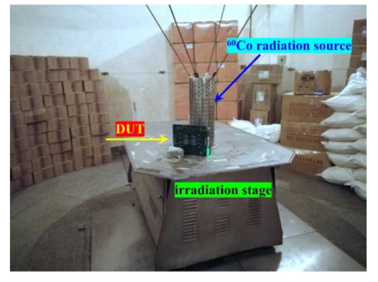
As shown in Figure 2, TID exposures were carried out with 60 Co-γ ray at The Xinjiang Technical Institute of Physics and Chemistry, Chinese Academy of Sciences, with dose rate of 200 rad(Si)/s. A data pattern of 55 h was written into SRAM before irradiation, and it was then set to data hold operation during irradiation. Different devices from the same wafer were chosen for two times of SEU tests. For Kr ion, we chose nine devices and divided them into three groups, with one group irradiated to 200 krad(Si), another group irradiated to 400 krad(Si), and the last group being the reference sample without TID irradiation. Additionally, six devices were divided into two groups for Bi ion SEU test: 800 krad(Si) and reference sample without TID irradiation.

2.3. Heavy Ion Irradiation

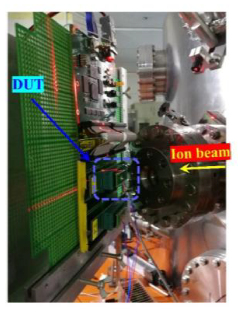
As shown in Figure 3, the heavy ion irradiation experiments were performed at the heavy ion research facility in Lanzhou (HIRFL) in the Institute of Modern Physics, Chinese Academy of Sciences. The ion species, energy, LET, and range are shown in Table 1. The LET values calculated by SRIM2013 [34] varied from 20.5 to 99.8 MeV·cm2/mg. In the following experiments, the LET values were at the device surface. The ion ranges in silicon were always greater than 50 µm. Three levels of metal were applied to the SOI SRAM studied in this paper, and the thickness of the overlayer was measured at 7.2 μm. The range of Kr and Bi ion was enough to punch through the silicon film of our 130-nm SOI SRAM because the thickness of silicon film was only 260 nm. The SEU cross-sections of SRAMs were characterized in a dynamic mode, i.e., the SRAMs were written with a specific pattern to the memory array, and the read repeatedly and errors were counted until 200 errors were recorded. To evaluate the effect of the data pattern applied during TID exposure on SEU hardness, the SEU characterizations were performed with TID data pattern 55h and its complement data pattern AAh.

3. Experimental Results

3.1. Effect of TID on the 6T SRAM SEU cross-section

Figure 4 provides the results for the SEU cross-sections of 6T SRAM characterized by Kr ion of devices in three different groups: (1) fresh; (2) after deposition of 200 krad(Si); and (3) 400 krad(Si). The mean value of SEU data with an error bar at each dose level is depicted in Figure 4. As shown in Figure 4, SEU cross-section of 6T SRAM increased by a factor of 0.1% (20.5 MeV·cm2/mg), 12.9% (27.2 MeV·cm2/mg), and 5.2% (37.6 MeV·cm2/mg) of after deposition of 200 krad(Si), with respect to the fresh condition, and increased by a factor of 3.7% (20.5 MeV·cm2/mg), 4.0% (27.2 MeV·cm2/mg), and 13.7% (37.6 MeV·cm2/mg) of after deposition 400 krad(Si). It can be clearly observed that the SEU cross-section of 6T SRAMs shows an increasing trend after TID irradiation, and the maximum increase is 13.7%.
Zheng et al. investigated the effect of the total dose effect on the SEU cross-section of the SRAMs. The experimental results show that the SEU cross-section of the SRAMs gradually increases after the TID irradiation, and the main oxide trap charge regions of the nanoscale feature device are the buried oxide and shallow trench isolation oxide regions [27,31,35,36,37]. For the test chip we designed, the SEU cross-section of the 6T SRAM increases slightly after TID irradiation, due to two main reasons: (1) the gate oxide layer thickness of our test chip is only 1.5 nm, so the gate oxide layer cannot trap enough trap charges; (2) the transistor used in the test chip adopts the structure of body under source FET (BUSFET), which eliminates the formation of parasitic leakage channels between the source and drain electrodes caused by the radiation-induced charges trapped in buried oxide (BOX). Therefore, the radiation-induced charges trapped in the shallow trench isolation oxide (STI), rather than in the BOX, were responsible for the increase of the SEU cross-section of the 6T SRAM.

3.2. Effect of Data Pattern on the 6T SRAM SEU cross-section

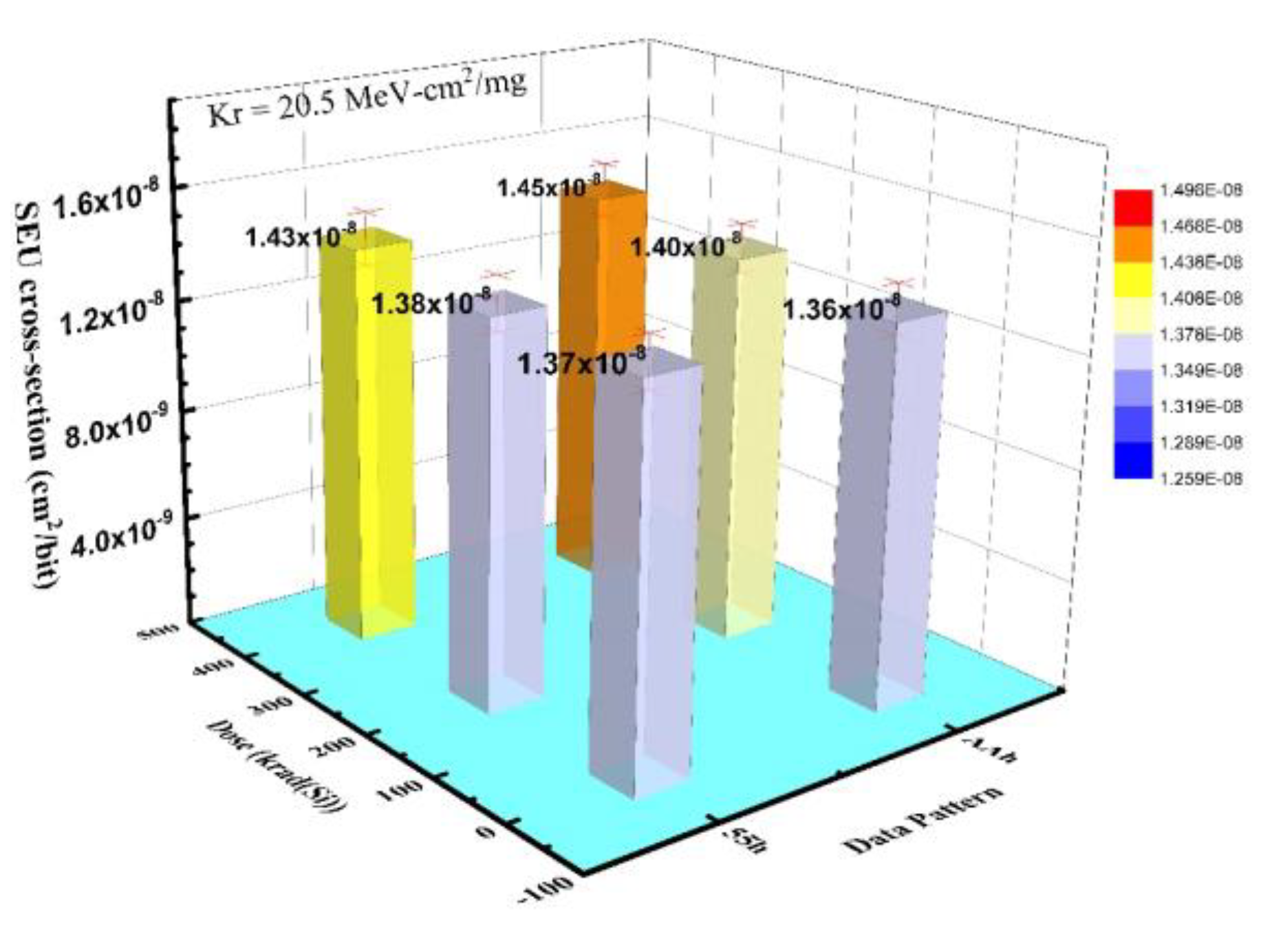
Figure 5 provides the results for the SEU cross-sections characterized by the Kr ion (20.5 MeV·cm2/mg) of devices in three different groups: (1) fresh; (2) after deposition of 200 krad(Si); and (3) 400 krad(Si). The mean value of SEU data with error bar at each dose level is depicted in Figure 5. As shown in Figure 5, the mean SEU cross-section of 6T SRAM increases by a factor of 0.1% (55 h), 2.8% (AAh) after deposition 200 krad(Si), with respect to the fresh condition, and it increases by a factor of 3.7% (55h), 6.8% (AAh) after deposition 400 krad(Si). It was observed that the data patterns have little effect on the SEU cross-section of the 6T SRAM after TID irradiation. There are two main reasons for these experimental results. First, the degree of ionization damage of the ultrathin gate oxide layer at 1.5 V was basically the same as the case without voltage addition; second, the main sensitive area of TID of the nanodevice shifted from the gate oxide region to the STI and BOX regions. Therefore, the SEU cross-section of the 6T SRAM after TID irradiation dose had no dependence on the data pattern that was applied during TID exposure.

3.3. Effect of TID on the 7T SRAM SEU cross-section

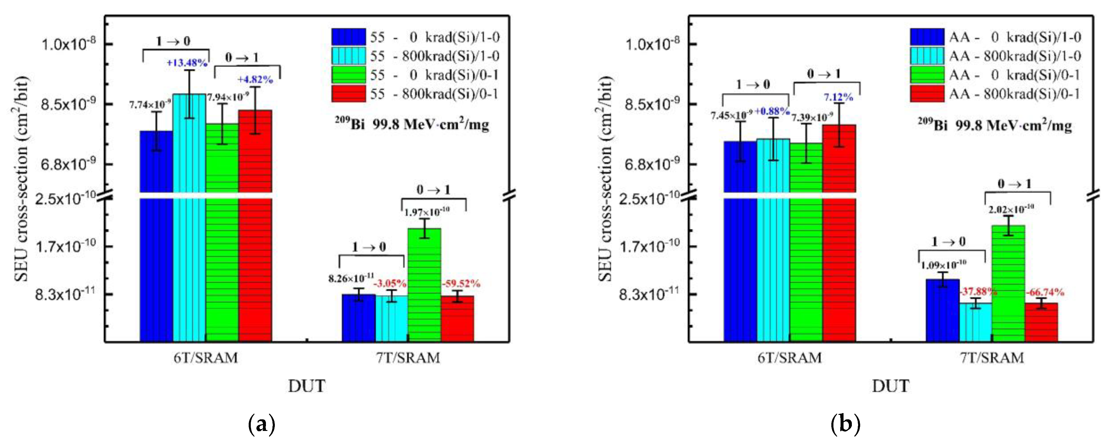
Figure 6 shows the SEU cross-sections of 6T SRAM and 7T SRAM characterized by the Bi (99.8 MeV·cm2/mg) ion as a function of TID. The SEU cross-sections of 6T SOI SRAM characterized by Bi ion are also increased by TID. As shown in Figure 6, the SEU cross-section of 6T SRAM increased by a factor 9.1% (55 h) and 4.0% (AAh) of after deposition 800 krad(Si), with respect to the fresh condition. Similarly, we did not observe a significant correlation between the SEU cross-section and data pattern applied during TID exposure for 7T SRAM. However, it is interesting to note that the SEU cross-section of the 7T SRAM showed an opposite changing trend to the 6T SRAM. As shown in Figure 6, SEU cross-section of 7T SRAM decreased by factors of 42.9% (55 h) and 56.6% (AAh) after deposition 800 krad(Si), with respect to the fresh condition. Because the 6T SRAM and 7T SRAM were fabricated in the same wafer, the physical dimensions and electrical characteristics of all transistors (N1, N2, N3, N4, P1, and P2) in the memory cell are very similar, except for the delay-hardened transistor, N5. Therefore, we can conclude that the change in the electrical characteristics of the N5 was responsible for the reduction in the SEU cross-section of the 7T SRAM after TID irradiation.
Furthermore, we investigated the TID effect on the “1→0” upset and “0→1” upset for 7T SRAM SEU types. As shown in Figure 7, the mean “1→0” upset cross-section of 7T SRAM decreased by a factor of 3.1% (55 h), 37.9% (AAh) of after deposition 800 krad(Si), with respect to the fresh condition, and the mean “0→1” upset cross-section decreased by a factor of 37.9% (55 h), 66.7% (AAh) after deposition 800 krad(Si). Therefore, the decrease of the cross-section of “0→1” upset was mainly responsible for the decrease of 7T SRAM SEU cross-section.

4. Discussion

4.1. Transient Propagation Circuit Analysis for 7T SRAM

It is generally believed that, in silicon, electrons have much higher mobility than holes, resulting in the electrons are quickly collected at the drain contacts. Thus, the pull-down nMOSFET biased OFF-state determines the SEU resistance of the 7T SRAM. The equivalent circuits of transient pulse propagation, corresponding to two different SEU types in the 7T SRAM, are shown in Figure 8.
As shown in Figure 8a, when the Q node is set to low potential, the pull-down nMOSFET N1 in the inverter 1 is turned OFF. Normally, incident heavy ions hitting the N1 will produce a transient pulse, caused by charge collection in the drain. After that, the transient pulse acts on the gate of inverter 2 to gradually increase the potential of the Q node. The potential perturbation in the Q node well further feeds back to the gate of inverter 1 through the delay transistor N5 to gradually decrease the potential of the Q node. Finally, the single event transient pulse signal is latched to the memory cell of the 7T SRAM. In this case, the delay transistor N5 indirectly delayed and suppressed the feedback signal of the single event transient pulse, so that the delay-efficiency was lower; thus, the cross-section of “0→1” upset was higher.
As shown in Figure 8b, when the Q node was set to the high potential, the pull-down nMOSFET N2 in the inverter 2 was turned OFF, when the incident heavy ions hitting the N2 produced a transient pulse, caused by charge collection in the drain. After that, the transient pulse through the delay transistor N5 acted on the gate of inverter 1 to gradually increase the potential of the Q node. The potential perturbation in the Q node well further fed back to the gate of inverter 1 to gradually decrease the potential of the Q node. Finally, the single event transient pulse signal was latched to the memory cell of the 7T SRAM. In this case, the delay transistor N5 directly delayed and suppressed the single event transient pulse, so that the delay-efficiency was higher; thus, the cross-section of “1→0” upset was lower.

4.2. Effect of TID on the OFF-State Equivalent Resistance of Delay Transistor N5

According to previous studies, TID irradiation significantly affects the device’s carrier mobility [37,38,39,40]. As shown in the equation 1, the carrier mobility of the transistors was mainly affected by three scatterings: phonon scattering, surface scattering, and charged impurity scattering. It has been found that the scattering rate of charged impurities is mainly determined by the semiconductor process, and it is rarely affected by TID. However, phonon and surface scattering are proportional to the electric field intensity perpendicular to the channel direction; the higher the density of oxide trap charge is, the stronger the vertical electric field component is. Therefore, the effect of the TID on the carrier scattering rate was mainly to increase the phonon and surface scattering rates.
1 μ n = 1 μ 1 ( E e f f ) | α 1 | + 1 μ 2 ( E e f f ) | α 2 | + 1 μ 3 Q ot ( 1 N i ) α 3
where α i and μ i are the fitting parameters, N i is the charge density of inversion layer, E e f f is effective vertical electric field intensity, and Q o t   is the oxide trap charge density.
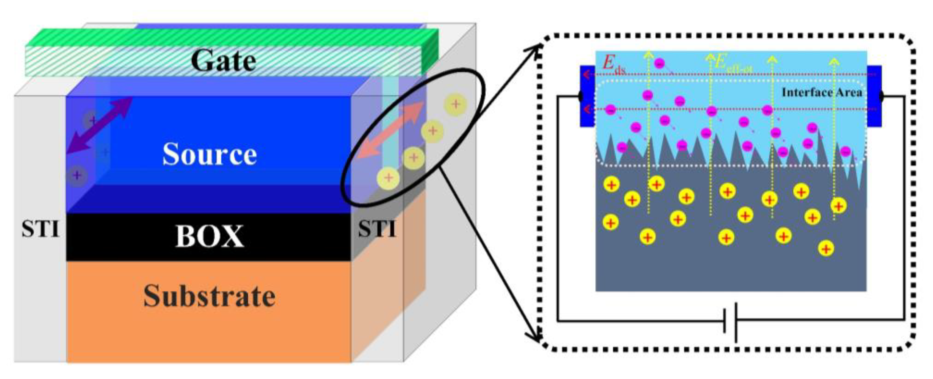
As shown in Figure 9, a substantial amount of radiation-induced charge was trapped in the STI and BOX of the delay transistor N5 after TID radiation. As a result, the oxide trapped charge generated a vertical electric field in the channel region of the transistor N5. This results in an increase in phonon and surface scattering. Finally, the carrier mobility rate of the delay transistor N5 decreased, and the equivalent OFF-state resistance increased, thus leading to a decrease in the SEU cross-section of the 7T SRAM.

4.3. The Advantages of Suppressing SEU with TID

In the natural space radiation environment, there are protons and electrons that can cause TID effects, as well as heavy ions that can cause transient SEE. When the integrated circuit is on-orbit, it will be affected by a variety of radiation effects; that is, there is electrical performance degradation caused by TID, and there is also the transient voltage pulse caused by SEE. Hence, TIDs and SEEs have a natural synergy in the space radiation environment. We found that, when delay transistors are used for hardened circuit design, the TID can cause degradation in the performance of delay transistors, thus suppressing the SEU. Therefore, not only does using delay-hardened transistors for hardened circuit design not affect the operating speed of nano-devices, it also improves the stability of memory cells. Furthermore, the TID effect can be used to suppress the transient SEE and achieve self-optimizing design in natural radiation space radiation environments. Our study provides new insight into radiation-hardened by design (RHBD) technology for nano-integrated circuits.

5. Conclusions

The total ionizing dose (TID) effects on single-event upset (SEU) hardness of silicon-on-insulator (SOI) static random access memories (SRAMs) with 6T and 7T cell designs were explored in this paper. Experimental results show that the SEU cross-section of 6T SOI SRAM is increased by TID and has no dependence on the data pattern applied during TID exposure. However, it is interesting to note that the SEU cross-section of 7T SRAM decreases significantly after TID exposure. Furthermore, in our experiment, opposite changes intendencies of SEU cross-section for 6T and 7T SOI SRAMs were observed after TID irradiation. The mechanism behind the experimental results of 6T SRAM is that OFF-state leakage of pull-down nMOSEFTs increases after TID irradiation, since the parasitic transistor is turned ON by radiation in the shallow trench isolation oxide (STI) region. However, the radiation-induced decrease in carrier mobility in delay transistor N5 of the 7T SRAM is responsible for the decrease of the SEU cross-section. Because radiation-induced charges trapped in the STI and buried oxide (BOX) improve the carrier scattering rate, the OFF-state equivalent resistance of delay transistor N5 increases, causing the stronger suppression of transient pulses and feedback signals, ultimately leading to SEU cross-section decreases. Our experimental results provide a new insight into the radiation-hardened by design (RHBD) used in nano ICs.

Author Contributions

Conceptualization, P.Z.; data curation, P.Z.; formal analysis, P.Z., B.L., and H.L.; funding acquisition, P.Z. and J.L.; investigation, P.Z., B.L., and H.L.; project administration, P.Z. and J.L.; supervision, J.L.; validation, J.Y., Y.J., Q.C., and Y.S.; writing—original draft, P.Z.; writing—review and editing, J.L. All authors have read and agreed to the published version of the manuscript.

Funding

This research was funded by the National Natural Science Foundation of China (Nos. 12105341, 61874135, and 12035019).

Data Availability Statement

Data available on request due to restrictions eg privacy.
The data presented in this study are available on request from the corresponding author. The data are not publicly available due to the research results having potential commercial value.

Acknowledgments

We acknowledge the support of the HIRFL in heavy-ion irradiation and for the TID irradiation equipment in the Xinjiang Technical Institute of Physics and Chemistry, Chinese Academy of Sciences.

Conflicts of Interest

The authors declare no conflict of interest.

References

  1. Barth, J.L.; Dyer, C.S.; Stassinopoulos, E.G. Space, atmospheric, and terrestrial radiation environments. IEEE Trans. Nucl. Sci. 2003, 50, 466–482. [Google Scholar] [CrossRef] [Green Version]
  2. Xapsos, M. A Brief History of Space Climatology: From the Big Bang to the Present. IEEE Trans. Nucl. Sci. 2019, 66, 17–37. [Google Scholar] [CrossRef] [Green Version]
  3. Dodd, P.E.; Massengill, L.W. Basic mechanisms and modeling of single-event upset in digital microelectronics. IEEE Trans. Nucl. Sci. 2003, 50, 583–602. [Google Scholar] [CrossRef]
  4. Baumann, R.C. Radiation-induced soft errors in advanced semiconductor technologies. IEEE Trans. Device Mater. Reliab. 2005, 5, 305–316. [Google Scholar] [CrossRef]
  5. Dodd, P.E.; Shaneyfelt, M.R.; Schwank, J.R.; Felix, J.A. Current and Future Challenges in Radiation Effects on CMOS Electronics. IEEE Trans. Nucl. Sci. 2010, 57, 1747–1763. [Google Scholar] [CrossRef]
  6. Kobayashi, D. Scaling Trends of Digital Single-Event Effects: A Survey of SEU and SET Parameters and Comparison With Transistor Performance. IEEE Trans. Nucl. Sci. 2021, 68, 124–148. [Google Scholar] [CrossRef]
  7. Binder, D.; Smith, E.C.; Holman, A.B. Satellite Anomalies from Galactic Cosmic Rays. IEEE Trans. Nucl. Sci. 1975, 22, 2675–2680. [Google Scholar] [CrossRef]
  8. Barillot, C.; Calvel, P. Review of commercial spacecraft anomalies and single-event-effect occurrences. IEEE Trans. Nucl. Sci. 1996, 43, 453–460. [Google Scholar] [CrossRef]
  9. Normand, E. Single-event effects in avionics. IEEE Trans. Nucl. Sci. 1996, 43, 461–474. [Google Scholar] [CrossRef]
  10. Harboe-Sorensen, R.; Poivey, C.; Zadeh, A.; Keating, A.; Fleurinck, N.; Puimege, K.; Guerre, F.X.; Lochon, F.; Kaddour, M.; Li, L.; et al. PROBA-II Technology Demonstration Module In-Flight Data Analysis. IEEE Trans. Nucl. Sci. 2012, 59, 1086–1091. [Google Scholar] [CrossRef]
  11. Ecoffet, R. Overview of In-Orbit Radiation Induced Spacecraft Anomalies. IEEE Trans. Nucl. Sci. 2013, 60, 1791–1815. [Google Scholar] [CrossRef]
  12. Bessot, D.; Velazco, R. Design of SEU-hardened CMOS memory cells: The HIT cell. In Proceedings of the RADECS 93—Second European Conference on Radiation and its Effects on Components and Systems, St. Malo, France, 13–16 September 1993; pp. 563–570. [Google Scholar] [CrossRef]
  13. Calin, T.; Nicolaidis, M.; Velazco, R. Upset hardened memory design for submicron CMOS technology. IEEE Trans. Nucl. Sci. 1996, 43, 2874–2878. [Google Scholar] [CrossRef]
  14. Schwank, J.R.; Shaneyfelt, M.R.; Dodd, P.E. Radiation Hardness Assurance Testing of Microelectronic Devices and Integrated Circuits: Radiation Environments, Physical Mechanisms, and Foundations for Hardness Assurance. IEEE Trans. Nucl. Sci. 2013, 60, 2074–2100. [Google Scholar] [CrossRef]
  15. Hughes, H.L.; Benedetto, J.M. Radiation effects and hardening of MOS technology: Devices and circuits. IEEE Trans. Nucl. Sci. 2003, 50, 500–521. [Google Scholar] [CrossRef]
  16. Narasimham, B.; Gambles, J.W.; Shuler, R.L.; Bhuva, B.L.; Massengill, L.W. Quantifying the Effect of Guard Rings and Guard Drains in Mitigating Charge Collection and Charge Spread. IEEE Trans. Nucl. Sci. 2008, 55, 3456–3460. [Google Scholar] [CrossRef]
  17. Liu, X.; Cai, L.; Liu, B.; Yang, X.; Cui, H.; Li, C. Total Ionizing Dose Hardening of 45 nm FD-SOI MOSFETs Using Body-Tie Biasing. IEEE Access 2019, 7, 51276–51283. [Google Scholar] [CrossRef]
  18. Soliman, K.; Nichols, D.K. Latchup in CMOS Devices from Heavy Ions. IEEE Trans. Nucl. Sci. 1983, 30, 4514–4519. [Google Scholar] [CrossRef]
  19. Bruguier, G.; Palau, J.M. Single particle-induced latchup. IEEE Trans. Nucl. Sci. 1996, 43, 522–532. [Google Scholar] [CrossRef]
  20. Hsieh, C.M.; Murley, P.C.; Brien, R.R.O. Dynamics of Charge Collection from Alpha-Particle Tracks in Integrated Circuits. In Proceedings of the 1981 International Reliability Physics Symposium, Orlando, FL, USA, 7–9 April 1981; pp. 38–42. [Google Scholar]
  21. Schwank, J.R.; Ferlet-Cavrois, V.; Shaneyfelt, M.R.; Paillet, P.; Dodd, P.E. Radiation effects in SOI technologies. IEEE Trans. Nucl. Sci. 2003, 50, 522–538. [Google Scholar] [CrossRef]
  22. Barnaby, H.J. Total-Ionizing-Dose Effects in Modern CMOS Technologies. IEEE Trans. Nucl. Sci. 2006, 53, 3103–3121. [Google Scholar] [CrossRef]
  23. Schwank, J.R.; Shaneyfelt, M.R.; Fleetwood, D.M.; Felix, J.A.; Dodd, P.E.; Paillet, P.; Ferlet-Cavrois, V. Radiation Effects in MOS Oxides. IEEE Trans. Nucl. Sci. 2008, 55, 1833–1853. [Google Scholar] [CrossRef]
  24. Raine, M.; Hubert, G.; Gaillardin, M.; Paillet, P.; Bournel, A. Monte Carlo Prediction of Heavy Ion Induced MBU Sensitivity for SOI SRAMs Using Radial Ionization Profile. IEEE Trans. Nucl. Sci. 2011, 58, 2607–2613. [Google Scholar] [CrossRef]
  25. Raine, M.; Gaillardin, M.; Lagutere, T.; Duhamel, O.; Paillet, P. Estimation of the Single-Event Upset Sensitivity of Advanced SOI SRAMs. IEEE Trans. Nucl. Sci. 2018, 65, 339–345. [Google Scholar] [CrossRef]
  26. Liu, M.S.; Liu, H.Y.; Brewster, N.; Nelson, D.; Golke, K.W.; Kirchner, G.; Hughes, H.L.; Campbell, A.; Ziegler, J.F. Limiting Upset Cross Sections of SEU Hardened SOI SRAMs. IEEE Trans. Nucl. Sci. 2006, 53, 3487–3493. [Google Scholar] [CrossRef]
  27. Schwank, J.R.; Shaneyfelt, M.R.; Felix, J.A.; Dodd, P.E.; Baggio, J.; Ferlet-Cavrois, V.; Paillet, P.; Hash, G.L.; Flores, R.S.; Massengill, L.W.; et al. Effects of Total Dose Irradiation on Single-Event Upset Hardness. IEEE Trans. Nucl. Sci. 2006, 53, 1772–1778. [Google Scholar] [CrossRef]
  28. Pereira, E.C.F.; Gonçalez, O.L.; Vaz, R.G.; Federico, C.A.; Both, T.H.; Wirth, G.I. The effects of total ionizing dose on the neutron SEU cross section of a 130 nm 4 Mb SRAM memory. In Proceedings of the 2014 15th Latin American Test Workshop—LATW, Fortaleza, Brazil, 12–15 March 2014; pp. 1–4. [Google Scholar]
  29. Xiao, Y.; Guo, H.-X.; Zhang, F.-Q.; Zhao, W.; Wang, Y.-P.; Zhang, K.-Y.; Ding, L.-L.; Fan, X.; Luo, Y.-H.; Wang, Y.-M. Synergistic effects of total ionizing dose on single event upset sensitivity in static random access memory under proton irradiation. Chin. Phys. B 2014, 23, 118503. [Google Scholar] [CrossRef]
  30. Artola, L.; Gaillardin, M.; Hubert, G.; Raine, M.; Paillet, P. Modeling Single Event Transients in Advanced Devices and ICs. IEEE Trans. Nucl. Sci. 2015, 62, 1528–1539. [Google Scholar] [CrossRef]
  31. Zheng, Q.; Cui, J.; Liu, M.; Zhou, H.; Liu, M.; Wei, Y.; Su, D.; Ma, T.; Lu, W.; Yu, X.; et al. Total Ionizing Dose Influence on the Single-Event Upset Sensitivity of 130-nm PD SOI SRAMs. IEEE Trans. Nucl. Sci. 2017, 64, 1897–1904. [Google Scholar] [CrossRef]
  32. Zheng, Q.; Cui, J.; Lu, W.; Guo, H.; Liu, J.; Yu, X.; Wei, Y.; Wang, L.; Liu, J.; He, C.; et al. The Increased Single-Event Upset Sensitivity of 65-nm DICE SRAM Induced by Total Ionizing Dose. IEEE Trans. Nucl. Sci. 2018, 65, 1920–1927. [Google Scholar] [CrossRef]
  33. Schwank, J.R.; Shaneyfelt, M.R.; Draper, B.L.; Dodd, P.E. BUSFET-a radiation-hardened SOI transistor. IEEE Trans. Nucl. Sci. 1999, 46, 1809–1816. [Google Scholar] [CrossRef]
  34. Ziegler, J.F.; Ziegler, M.D.; Biersack, J.P. SRIMThe stopping and range of ions in matter. Nucl. Instrum. Methods Phys. Res. Sect. B Beam Interact. Mater. At. 2010, 268, 1818–1823. [Google Scholar] [CrossRef] [Green Version]
  35. Schwank, J.R.; Dodd, P.E.; Shaneyfelt, M.R.; Feli, J.A.; Hash, G.L.; Ferlet-Cavrois, V.; Paillet, P.; Baggio, J.; Tangyunyong, P.; Blackmore, E. Issues for single-event proton testing of SRAMs. IEEE Trans. Nucl. Sci. 2004, 51, 3692–3700. [Google Scholar] [CrossRef]
  36. Faccio, F.; Cervelli, G. Radiation-induced edge effects in deep submicron CMOS transistors. IEEE Trans. Nucl. Sci. 2005, 52, 2413–2420. [Google Scholar] [CrossRef] [Green Version]
  37. Faccio, F.; Michelis, S.; Cornale, D.; Paccagnella, A.; Gerardin, S. Radiation-Induced Short Channel (RISCE) and Narrow Channel (RINCE) Effects in 65 and 130 nm MOSFETs. IEEE Trans. Nucl. Sci. 2015, 62, 2933–2940. [Google Scholar] [CrossRef]
  38. Wu, X.; Lu, W.; Wang, X.; Xi, S.-B.; Guo, Q.; Li, Y.-D. Total ionizing dose effect on 0.18 μm narrow-channel NMOS transistors. Acta Phys. Sin. 2013, 62, 136101. [Google Scholar] [CrossRef]
  39. Zhou, H.; Cui, J.-W.; Zheng, Q.-W.; Guo, Q.; Ren, D.-Y.; Yu, X.-F. Reliability of partially-depleted silicon-on-insulator n-channel metal-oxide-semiconductor field-effect transistor under the ionizing radiation environment. Acta Phys. Sin. 2015, 64, 086101. [Google Scholar] [CrossRef]
  40. Zhang, H.; Bi, J.; Wang, H.; Hu, H.; Li, J.; Ji, L.; Liu, M. Study of total ionizing dose induced read bit errors in magneto-resistive random access memory. Microelectr. Reliab. 2016, 67, 104–110. [Google Scholar] [CrossRef]
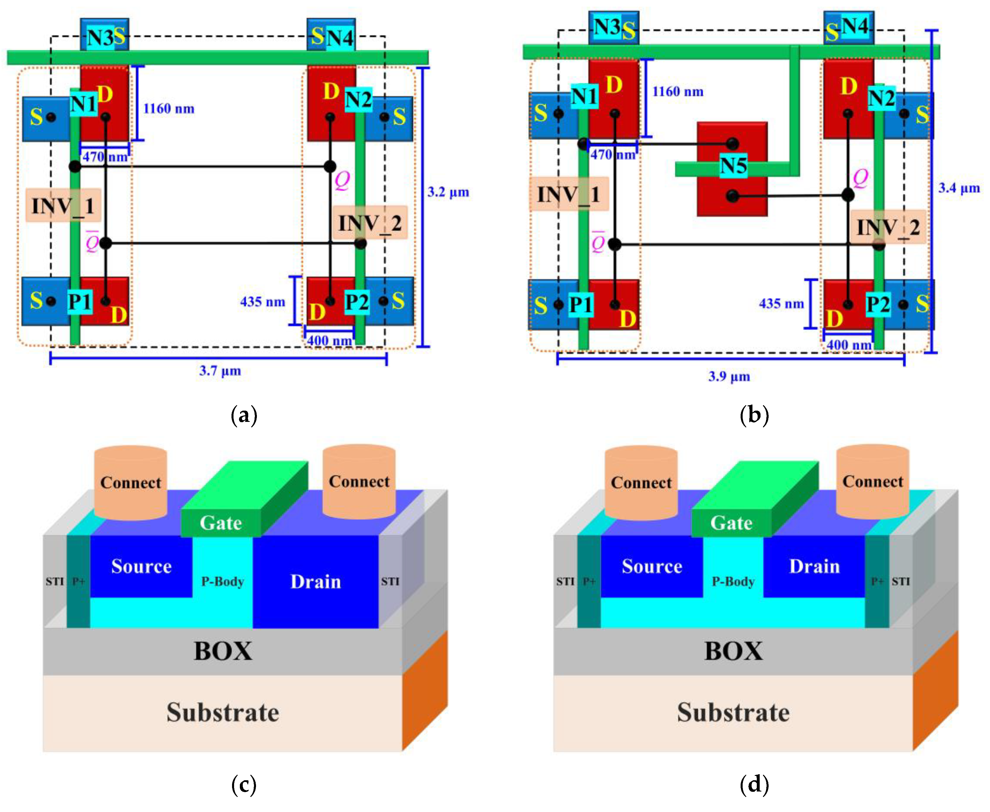
Figure 1. Schematics of memory cell structure of (a) 6T SRAM, (b) 7T SRAM, (c) BUSFET (body under source FET) structure of N1, N2, N3, N4, P1, P2, and (d) delay transistor N5 structure.
Electronics 11 03188 g001
Figure 2. DUT in the terminal of the 60Co irradiation.
Electronics 11 03188 g002
Figure 3. DUT in the terminal of the heavy-ion beamline.
Electronics 11 03188 g003
Figure 4. SEU cross-sections versus LET for 6T SRAMs. The purple horizontal column represents data for TID = 0 rad(Si), the green vertical column represents data for TID = 200 krad(Si), and the pink checkerboard represents data for TID = 400 krad(Si).
Electronics 11 03188 g004
Figure 5. SEU cross-sections characterized by Kr ion versus TID for 6T SRAMs under different data patterns.
Electronics 11 03188 g005
Figure 6. SEU cross-sections characterized by Bi ion versus layout structure for SOI SRAMs. The vertical column represents data for TID = 0 rad(Si), and the horizontal column represents data for TID = 800 krad(Si). The data pattern applied during SEU testing was (a) 55h and (b) AAh.
Electronics 11 03188 g006
Figure 7. SEU cross-sections characterized by Bi ion versus layout structure for SOI SRAMs after deposition 800 krad(Si). The vertical column represents data for the “1→0” upset, the horizontal column represents data for the “0→1” upset. The data pattern applied during SEU testing is (a) 55h and (b) AAh.
Electronics 11 03188 g007
Figure 8. The equivalent circuits of transient pulse propagation corresponding to the (a) “0→1” upset type and (b) “1→0” upset type in the 7T SRAM.
Electronics 11 03188 g008
Figure 9. Schematic illustration of the physical mechanism of radiation-induced carrier scattering rate increases in the delay transistor N5 of the 7T SRAM.
Electronics 11 03188 g009
Table 1. Ion spices, energy, LET, and range in silicon.
Ion SpeciesAir/Al-Foil
(mm)/(μm)
Energy at Device Surface
(MeV)
LET at Device Surface
(MeV·cm2/mg)
Ion Range
(μm)
86Kr30/0184120.5274
50/100115427.2150
50/18048037.659
209Bi30/092399.854
Publisher’s Note: MDPI stays neutral with regard to jurisdictional claims in published maps and institutional affiliations.