1. Introduction
Mobility, transportation, and industrial systems are increasingly electric, from the drivetrain to the auxiliaries, driven by improvements in battery performance and lifetime, government and private mandates to reduce greenhouse gas emissions, and an improved user experience. This electrification includes the traction systems in electric vehicles, but the auxiliary systems must also be electrified with power-dense, efficient, and reliable power conversion stages under unique operating conditions and constraints. In particular, electromechanical systems—including pumps, compressors, and blowers—are required on nearly every vehicle and require VSDs for efficient operation.
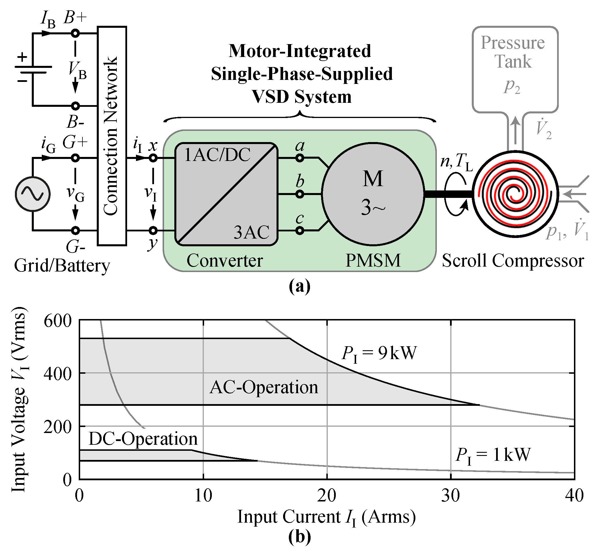
An on-board compressor system for the air brakes of railway vehicles was considered here, as shown in
Figure 1a. This oil-free scroll compressor [
1]—selected for high pressure, low noise, and long maintenance intervals (see [
2] for a comparison of compressors)—was used to charge the pressure tank that supplies the air brakes, pantograph, and other critical loads driven by air pressure, necessitating ultra-high reliability. As such, the compressor system is supplied from a tertiary traction transformer winding during normal operation (“grid operation”), as is typical for auxiliary railway applications [
3], and from an on-board battery during startup or extended grid interruptions, with a reduced output power. The key specifications for this particular application are given in
Table 1. While, in this work, the focus was on the single-phase to three-phase VSD power conversion system for this particular application, the requirements for single-phase to three-phase variable-speed conversion are quite general (e.g., a 10
, 230 Vrms, single-phase VSD in [
4], or a single-phase to three-phase VSD with Power Factor Correction (PFC) operation in [
5]).
With a VSD system required to increase compressor performance [
6], the application needs a power electronics system to convert the single-phase AC—or DC, under battery operation—input voltage into a symmetrical three-phase voltage system, where the magnitude and frequency can be adjusted to control the motor speed (and, accordingly, output power). A three-phase Permanent Magnet Synchronous Motor (PMSM) was selected for high torque, low weight, high efficiency, and compactness [
7]. The VSD was designed for 9
of output power (see
Figure 1b), to meet the required
of mechanical output power (
Table 1) while accounting for system losses and acceleration, must comply with CISPR 11/Class A [
8], and must operate under unity power factor operation to minimize harmonic distortion and reactive grid power [
9].
Table 1.
Key system specifications.
Table 1.
Key system specifications.
| Air Flow Rate at Pressure | 850 L min−1, 0.83 MPa |
| Nominal Speed () | 3700 rpm |
| Nominal Mech. Power, Grid () | kW |
| Nominal Mech. Power, Batt. () | kW |
| Nominal Grid Voltage () | 400 Vrms |
| Grid Voltage Range () | 280 Vrms to 530 Vrms |
| Grid Frequency () | 50 Hz |
| Battery Voltage Range () | 70 Vdc to 120 Vdc |
| EMI Standard (Input) | CISPR 11/Class A [8] |
Conventionally, these power conversion systems are realized with a two-stage system [
10] comprising a front-end PFC rectifier, an electrolytic DC-link capacitor to buffer the power pulsation from the single-phase grid supply, and a VSD inverter to drive the motor and compressor [
11]. For auxiliary motor drive applications, though, efficiency is not the primary concern—due to the low duty-cycle of operation—and the power density should be maximized for the space- and weight-constrained mobility application. The highest-power-density solution, in the end, is a motor-integrated drive system [
12], which eliminates expensive shielded cables [
13] and cable reflections [
14], which allows for higher slew rates of the inverter stage power semiconductor switching voltage transitions and/or lower switching losses, exhibits better Electromagnetic Interference (EMI) behavior [
12] from integration in a single housing, and allows for combined cooling of the electronics and motor [
15]. Motor-integrated VSDs, in sum, result in lower installation and operating costs, but require the integration of all drive components—even the EMI input filter [
16]. The requirement for electrolytic capacitors as the single-phase power buffer, though, prevents motor integration, with the elevated operating temperatures [
17] of the integrated converter (85
to 105
) [
18] degrading lifetime [
19] and/or requiring substantial overdimensioning of these large capacitors.
For the highly desired motor integration of the converter system for these single-phase to three-phase drive applications, then, alternatives to the traditional two-stage approach with an electrolytic capacitor are required. Solutions that synergistically employ the components are considered first. Ultra-low-cost implementations use the grid voltage effectively as one of the motor line-to-line voltages and employ four power MOSFETs and a TRIAC [
20], but do not allow a wider range of speed control. To utilize the motor star point as one of the connecting points to the single-phase grid, the motor leakage inductance may be utilized as a boost inductor [
21], but this results in unacceptably high voltage stresses (twice the grid peak voltage) for this application, which already features a high-grid-input voltage. The same issue occurs in a low-cost implementation that employs a front-end PFC rectifier with only one bridge-leg and a split DC-link [
22]. Coupled power electronics (rectifier to inverter) approaches, such as Z-source-based concepts [
23] or matrix converters [
24], typically feature an (integrated) active buffer for power decoupling [
25], a basic requirement since the matrix converter does not include energy storage [
26], which drives the complexity and high component stresses. Current-source structures [
27], in the end, only replace the boost inductor with a DC-link inductor (since voltage-source inverters do not require an output filter here) while requiring bidirectional switches, and therefore do not improve the potential for integration. The synergistic approaches, then, do not hold the promise of eliminating the large energy storage components required to buffer the single-phase power pulsation—and if they do start to alleviate the requirement, the penalties appear unacceptably high.
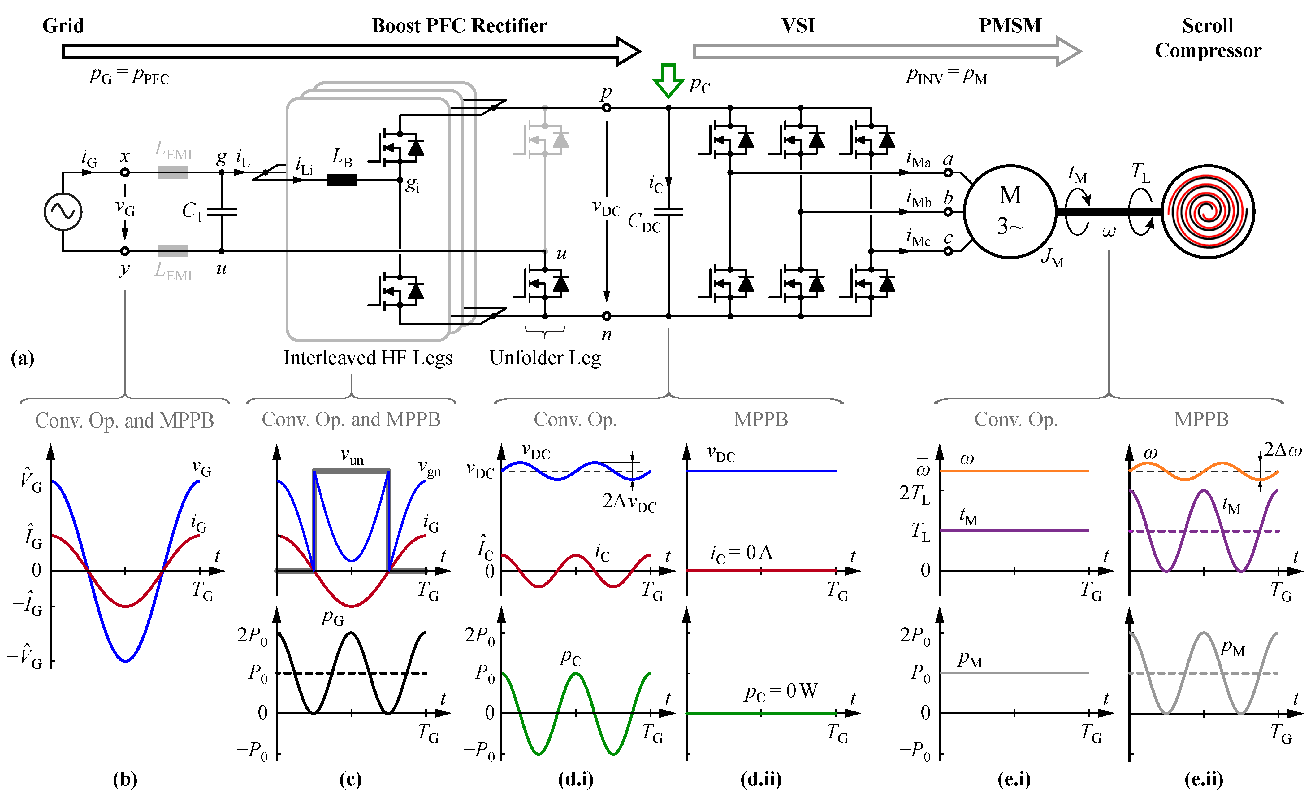
Accordingly, this work proposes to use the motor (and load) inertia as a power buffer, eliminating the need for power buffering in the DC-link capacitors, an approach called the MPPB and introduced in [
28]. A conventional two-stage structure was utilized, with a single-phase front-end PFC rectifier and a three-phase VSD inverter, with the power flow for a conventional system and the MPPB system shown in
Figure 2a. Although particular rectifier and inverter topologies were selected and demonstrated here, the findings are applicable to any specific implementation of the rectifier and inverter.
The MPPB concept was previously proposed with the PFC rectifier omitted and the inverter stage directly supplied from a single-phase-grid diode bridge rectifier [
29]. This concept results in a rectifier sine wave voltage at the DC-link, so the input current is only sinusoidal if the motor voltage stays below the rectified input voltage [
30]. This concept, then, is limited to motors with a low back Electromotive Force (EMF) and/or applications where a large speed variation is acceptable—but in both cases, a unity power factor cannot be achieved. In [
31], a solution to this problem was proposed, where a reactive current component was injected into the motor to keep the back EMF of the motor below the input voltage. Here, the PFC rectifier can indeed be omitted, but the small motor inductance leads to large motor currents and excessive losses. With this constraint and the large fluctuating DC-link voltage, which increase the system complexity, applications for this approach are restricted to drive systems with special low-voltage motors that do not operate at common voltages.
In this work, a single-phase-supplied electrolytic-less VSD system with dedicated rectifier and inverter stages that realizes a high lifetime and reduced volume for motor integration is designed, modeled, and implemented. In
Section 2, the rectifier and inverter topologies are selected, introduced, and evaluated with the concept and control of the novel proposed MPPB approach to eliminate electrolytic capacitors. In this section, the operational limits for the proposed approach are evaluated for different load cases. The novel control concept for MPPB operation is derived and explained in detail, with verification based on circuit simulation, and finally, the phase currents are investigated in detail to compare the performance of the novel MPPB approach to a conventional system.
Section 3 details the implementation of the motor-integrated drive system with volume and loss distributions, including showcasing the motor integration that is uniquely enabled by the novel, proposed MPPB approach.
Section 4 verifies the system operation in the time domain for the steady-state and transients, loss models across the full torque range, and EMI requirements and compares the system losses between the MPPB and conventional systems. In
Section 5, the extended functionality required for the considered application is demonstrated, including ride-through and battery-supplied operation. The novel control structure can also be employed for DC-supply operation with a single structure that simplifies the implementation and maintenance effort of the system.
Section 6 concludes and summarizes the MPPB approach and results of the work, with Appendices that specifically investigate low-speed operation in the context of the proposed approach (
Appendix A), controller design and future enhancements (
Appendix B) to reduce the DC-link voltage ripple (including novel feedforward terms), and the detailed phase currents under MPPB operation (
Appendix C).
4. Hardware Demonstration Verification
To evaluate the motor-integrated hardware demonstrator of
Figure 12, the overall operation of the drive system across the continuously varying operating points, motor drive speeds, and torque fluctuation was evaluated. Full operation cannot be validated with a resistor–inductor (RL) load alone, and a complete motor test bench was employed here (instead of driving the compressor itself). This test bench comprises a motor bed, the Device-Under-Test (DUT), a speed and torque sensor (
TM310 with a maximum torque bandwidth of 5 kHz from Magtrol [
84]), and a load motor operated with a commercially available drive system from Siemens with a constant load torque [
50]. An identical setup was employed for the no-load measurements of
Section 3. First, the concept was validated with time-domain measurements and waveforms. Then, the loss model was verified, and EMI measurements were taken before validating the extended functionality (distorted grid voltage, ride-through operation, and battery supply operation) in
Section 5.
Note that, due to the limited availability of the optimal
power semiconductors specified in
Table 3, all transistors were implemented as the
device (
C3M0032120K [
71]) for the following measurements.
4.1. Time-Domain Waveforms and Operation
Firstly, the theoretical aspects of
Section 2 were verified for the nominal operating point, as described in
Table 2. The measured waveforms are shown in
Figure 13, where the grid current (
Arms) and voltage were in-phase for unity power factor operation (measured at 99.95%) at
input power, a steady DC-link voltage near the reference of 650
, and a speed equal to the reference of 3700 rpm with a speed ripple so small that it is not visible on this oscilloscope capture. The low-frequency ripple of the DC-link voltage is investigated in depth in
Appendix B and corresponds here to 35 Vpkpk, nearly identical to the simulation results of 34 Vpkpk shown in
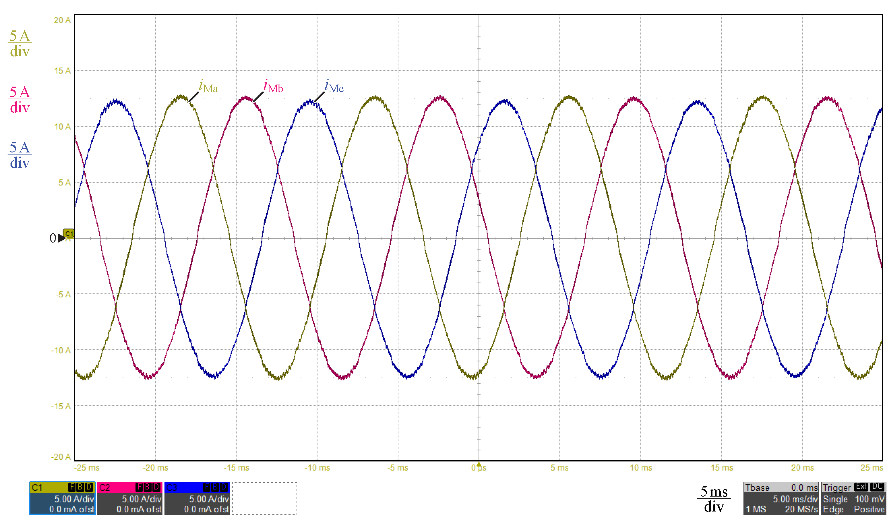
Figure 5. The measured motor currents are shown in
Figure 14, corresponding to a phase current stress of
Arms and, again, matching the theoretical results in both behavior and predicted amplitude. Overall, the system behavior was correct and expected, validating the MPPB approach and the predicted operation.
4.2. Efficiency
With the foundational operation of the MPPB approach verified, the introduced loss model was verified at nominal speed and DC-link voltage across the required mechanical output power range. Grid power input was measured with the
Yokogawa WT3000 precision power analyzer, and the mechanical quantities were measured with a speed and torque sensor. For all calculations, the measured stator phase resistance of
was used, as the system was verified for the short-time operation needed for this particular application. With the MPPB approach encompassing the complete system, the difference in the measured input (grid) and mechanical output powers was the drive system losses
. These measured losses are shown across load torque—and, accordingly, mechanical output power—as the bullet points in
Figure 15a. These measurements match the proposed loss model nearly precisely, validating both the proposed power converter and motor loss models under the proposed MPPB operation.
Next, the efficiency penalty associated with the significant power density increase of the MPPB concept was quantified, and the constructed MPPB system was compared to a conventional system with an electrolytic capacitor. The conventional system features lower phase current stresses, leading to lower currents and lower conduction losses in the motor and the inverter bridge-legs, but suffers from additional losses in the DC-link electrolytic capacitors. At the nominal output power, the system losses increase from 600
for a grid-to-motor-shaft efficiency of 92.6% in the conventional system with an electrolytic capacitor to 703
(91.4%) with the MPPB approach, for a loss increase of 103
, or 17%. This loss increase is the maximum across the operating load area, both in absolute and relative terms, with the load-dependent difference highlighted in blue in
Figure 15a.
Figure 15b shows the motor, converter, and drive system efficiencies for conventional and MPPB operation over the output power range, where the converter efficiencies are nearly identical at around 98%. The overall efficiency is primarily limited by the motor itself, with the extra losses in MPPB operation contributed mostly by the additional phase current stresses. The MPPB system achieves a grid-to-motor-shaft efficiency above 90% for all loads above 5 kW (66% of the nominal load), a high and flat efficiency for the exceptional power density of the motor-integrated, electrolytic capacitor-less MPPB-operated system.
4.3. Conducted EMI
Because the drive system was tested in full operation on the motor bed, all measurements for EMI were conducted according to CISPR 16 for floor-standing equipment [
85]. As discussed in the Introduction and highlighted in
Table 1, the conducted EMI of the drive system in the frequency range of 150 kHz to 30 MHz must comply with the CISPR 11/Class A QP limit [
8] (limits shown in
Figure 16).
Both phases
x and
y of the drive system were scanned with a maximum peak detector with a step size of 1%, a bandwidth of 9
, and a measurement time of 10
, and we report the results in
Figure 16.
Compliance with CISPR 11/Class A across the vast majority of the frequency space was verified, with only certain frequencies above 15 exceeding the limit and the largest QP violation of dB at MHz in phase y. Selected measurement points in this regime were verified with a CISPR 11 quasi-peak detector (“QP”) with a 1 measurement time. These peaks, however, are only caused by the EMI test condition, where the converter and motor were separated and connected with a cable for safety and measurement, and the completed system would achieve CISPR 11/Class A compliance across the full considered frequency range.
4.4. Transient Response
To this point, steady-state operation was assumed. Next, the transient behavior of the system was analyzed to verify the controller performance of the MPPB approach.
Figure 17 shows the system behavior for both a change in the reference speed and a step change in the instantaneous load torque.
The system begins in steady-state operation at 3000 rpm and with a nominal load torque of , and there are steady-state speed, torque, and DC-link voltage ripples, as previously discussed. At , the reference speed was increased linearly to over , and the input power and average motor power increased to ramp the motor speed to match this reference. The maximum applied instantaneous torque reaches 56 Nm, and this transient causes a small disturbance in the DC-link voltage with a maximum deviation of 40 V. This voltage disturbance decays after around 100 ms, and the speed reaches steady-state after 350 ms.
At
, the load torque decays instantaneously to 10 Nm, which is approximately half of the nominal torque. Again, the MPPB approach elegantly controls the system, with a short speed increase to 4169 rpm. The motor torque reaches steady-state after 100 ms, and the speed reaches steady-state after 350 ms. It should be noted that the DC-link voltage ripple will scale with the motor torque; cf.
Figure 17.
6. Conclusions
Motor integration of Variable-Speed Drive (VSD) systems is desired for power density, integration, cost, and reliability—but for single-phase-supplied applications, is limited by the need to provide buffering energy storage on the DC-link, which is typically accomplished with electrolytic capacitors. These electrolytic capacitors occupy significant converter volume and cannot be operated across a wide temperature range with a high lifetime, preventing these VSDs from motor integration for the next-generation of electrified mobility.
This work proposed that the kinetic energy stored in the motor inertia itself be used to buffer the pulsating power from the single-phase grid, translating DC-link voltage and current ripple to motor speed and torque ripple. This concept is named the Motor-Integrated Power Pulsation Buffer (MPPB), and the control technique and structure required for nominal and grid fault condition operation were analyzed deeply. The control was realized by rearranging the connections between the same top-level controllers—without changing the core controllers themselves—supporting retrofitting and a simple software change.
A hardware demonstrator was constructed to verify the proposed MPPB concept for a single-phase-supplied railway application that drives a scroll compressor for air brakes (and other loads that require high reliability). The demonstrator realized complete Permanent Magnet Synchronous Motor (PMSM) integration in a total volume of (or 500 in)—and without the DC-link capacitors that would occupy an additional 1 (or 61 in) and prevent integration. The MPPB system achieved over 90% grid-to-motor-shaft efficiency for all loads over 5 kW or 66% of the nominal load, with a worst-case loss penalty over a conventional electrolytic-capacitor-based system of only 17%. The demonstrator will achieve CISPR 11/Class A compliance at full integration and operates across the required suite of extended functionality, including for ride-through and sustained grid faults.
The proposed MPPB concept shifts the required grid-buffering energy storage from an additional electrical element—large DC-link capacitors—to the motor, which is already required for the mechanical drive, achieving otherwise unobtainable power densities and integration levels for single-phase-supplied variable-speed electric drives.


