Article

A Novel Power-Saving Reversing Camera System with Artificial Intelligence Object Detection

1
Institute of Electrical and Control Engineering, National Yang Ming Chiao Tung University, No. 1001, Hsinchu City 300093, Taiwan
2
Department of IC Design, Avisonic Technology Corporation, Hsinchu Science Park, Hsinchu City 30076, Taiwan
*
Author to whom correspondence should be addressed.
Electronics 2022, 11(2), 282; https://doi.org/10.3390/electronics11020282
Submission received: 19 December 2021 / Revised: 10 January 2022 / Accepted: 11 January 2022 / Published: 17 January 2022
(This article belongs to the Section Artificial Intelligence Circuits and Systems (AICAS))

Abstract

:
According to a study by the Insurance Institute for Highway Safety (IIHS), the driving collision rate of using only the reversing camera system is lower than that of using both the reversing camera system and the reversing radar. In this article, we implemented a reversing camera system with artificial intelligence object detection to increase the information of the reversing image. Our system consists of an image processing chip (IPC) with wide-angle image distortion correction and an image buffer controller, a low-power KL520 chip and an optimized artificial intelligence model MobileNetV2-YOLOV3-Optimized (MNYLO). The results of the experiment show the three advantages of our system. Firstly, through the image distortion correction of IPC, we can restore the distorted reversing image. Secondly, by using a public dataset and collected images of various weathers for artificial intelligence model training, our system does not need to use image algorithms that eliminate bad weathers such as rain, fog, and snow to restore polluted images. Objects can still be detected by our system in images contaminated by weather. Thirdly, compared with the AI model Tiny_YOLOV3, not only the parameters of our MNYLO have been reduced by 72.3%, the amount of calculation has been reduced by 86.4%, but the object detection rate has also been maintained and avoided sharp drops.

1. Introduction

According to World Health Organization (WHO) statistics, global traffic accidents cause more than 1.25 million deaths every year, and countries lose about 3% of their gross domestic product (GDP) [1]. The World Health Organization estimates that if there is no continuous improvement in the safety of drivers, traffic accidents will become the seventh leading cause of death in the world in 2030 [1]. Therefore, the current global automotive industry has a clear development trend toward intelligence, safety and energy-saving, and promotes the active development of the automotive electronics industry in four major areas such as advanced driver assistance systems, autonomous driving, Internet of Vehicles, and electric vehicles. Advanced driving assistance systems include Parking Aid System (PAS). The reversing radar and reversing camera system are well-known two kinds of advanced driver assistance systems included in PAS. The reversing radar uses sound to remind the driver that there are no obstacles around when reversing. It is basically not affected by light and weather conditions, and works well except the obstacle is too low or too thin. To avoid the shortcomings of the reversing radar, the reversing camera system provides the driver rear-views to assist reversing without collisions. The studies of The Insurance Institute for Highway Safety (IIHS) have shown that by comparing the collision probability of these four conditions, such as there is no auxiliary system at all, the reversing radar is used, the reversing camera system and the reversing radar are both used, and the reversing camera system is only used, the driving collision rates are 100%, 93.75%, 75% and 56%, respectively [2].
Although the collision rate of using reverse imaging is reduced, the reversing camera system still has two main disadvantages. The first disadvantage is that in order to obtain a wider view, the reversing camera system is usually equipped with a wide-angle lens. They usually result in image distortion. If the driver cannot easily figure out the distance against the obstacles, it will easily induce drivers’ misjudgment and increase the risk of collision. Therefore, the distorted image must be restored before using the information in the image. Fortunately, the problem of image distortion can be solved by image correction. Therefore, many scholars have made contributions to the issue of correcting distorted images [3,4,5,6,7,8]. In 2009, Junhee Park et al. proposed a distortion model defined on ideal undistorted coordinates to reduce computation time and maintain the high accuracy for achieving a fast and simple mapping for lens distortion correction [3]. In 2012, Jin Wei et al. presented an efficient and robust scheme for fisheye video correction, the optimization process is controlled by user annotation and takes into account a wide set of measures that are represented as a quadratic term in an energy minimization problem and leading to a closed-form solution via a sparse linear system [4]. In 2013, Junhee Park and Byung-Uk Lee proposed that in addition to using the distortion model to estimate the distortion coefficient through point correspondence, gradient components are also used to obtain the distortion coefficient to avoid that the corrected image corresponding to only the point may be overcompensated and produce curved lines in the opposite direction near the corners [5]. In 2018, Jun Li, Jie Su and Xiliang Zeng proposed a novel image distortion correction algorithm, which divides the distorted image into multiple quadrilaterals, and corrects the image distortion by calculating the position of the quadrilateral vertex and the parameters of the distortion to the bilinear model [6]. In 2020, Yibin He et al. proposed a fisheye image correction method that uses the difference between the distance between the distorted point and the non-distorted point to the image center to represent the degree of image distortion, and then uses different parameter curves for fitting and correction [7]. In 2020, Jiawen Weng et al. proposed a model-free lens distortion correction that determines the distortion displacement map of the whole distorted image by establishing the mathematical relationship of the distortion displacement and the modulated phase of the sinusoidal fringe pattern and then performs the image correction [8].
The second disadvantage of reverse imaging is that it is susceptible to weather. The reversing image obscured or polluted by weather conditions such as raindrops or haze will affect the accuracy of reversing driving. Therefore, many scholars are committed to image restoration processing technology to overcome the image degradation caused by rain [9,10,11,12,13,14,15] or fog [16,17,18,19,20,21,22,23,24] problem. In 2014, Shaodi You et al. proposed an idea which is to use long-range trajectories to discover the motion and appearance features of raindrops locally along the trajectories to detect raindrops and to utilize patches indicated to remove adherent raindrops [9]. In 2018, Rui Qian et al. proposed an attentive generative network which is injected visual attention into both the generative and discriminative networks to let the generative network pay more attention to the raindrop regions and the surrounding structures which are the regions that should be modified, and to let the discriminative network be able to assess the local consistency of the restored regions [10]. In 2018, Zhang, He and Patel, Vishal M presented a novel density aware multi-stream densely connected convolutional neural network-based algorithm, called DID-MDN, for joint rain density estimation and de-raining [11]. In 2019, Ren, Dongwei et al. presented the Progressive Recurrent Network (PReNet) and adopted intra-stage recursive computation of Residual Network (ResNet) in Progressive ResNet (PRN) and PReNet to reduce network parameters with unsubstantial degradation in de-raining performance [12]. In 2019, Fadi Al Machot et al. presented an approach for real-time raindrops detection which is based on Cellular Neural Networks (CNN) and Support Vector Machines (SVM) [13]. In 2020, Hao Luo et al. established a large-scale dataset named “RaindropCityscapes” covering a wide variety of raindrops and background scenarios and used a two-branch Multi-scale Shape Adaptive Network (MSANet) to detect and remove diverse raindrops [14]. In 2021, Xiaoyu Li et al. propose a method that first seeks to detect attention maps used to indicate the regions of the image that need to be restored and then restores the input frame by fetching clean pixels from adjacent frames to automatically remove these contaminants and produce a clean video [15].
In 2016, Amruta Deshmukh et al. proposed an algorithm which is using a novel ‘Mean Channel Prior (MCP)’ algorithm for defogging to get more accurate results [16]. In 2018, Engin, Deniz et al. applied bicubic downscaling to obtain low-resolution outputs from the network, utilized the Laplacian pyramid to upscale the output images to the original resolution, and enhanced Cycle Generative Adversarial Network (CycleGAN) formulation by combining cycle-consistency and perceptual losses in order to improve the quality of textural information recovery and generate visually better haze-free images [17]. In 2019, Qu Yanyun et al. proposed an Enhanced Pix2pix Dehazing Network (EPDN), which generates a haze-free image without relying on the physical scattering model [18]. In 2019, Zahid Tufail et al. proposed an algorithm that has four transmission maps adaptively selected according to the fog density to reconstruct the image with the optimal color contrast [19]. In 2020, Di Fan et al. proposed an image defogging algorithm to overcome the problems of low contrast and low definition of fog degraded image by three steps: firstly, transforming images from Red, Green, Blue (RGB) space to Hue, Saturation, Intensity (HSI) space and using two-level wavelet transform to extract features of image brightness components; secondly, using the K-Singular Value Decomposition (K-SVD) algorithm training dictionary and learns the sparse features of the fog-free image to reconstructed I-components of the fog image; thirdly, using the nonlinear stretching approach for saturation component improves the brightness of the image and then converts from HSI space to RGB color space to get the defog image [20]. In 2020, Gao Tao et al. proposed a novel defogging method that overcomes some limitations including imprecise estimation of atmospheric light, color distortion by both defining the more accurate atmospheric light by introducing the adaptive variable strategy and fusing dark channel and light channel to estimate more precise atmospheric light and transmittance [21]. In 2021, Sabiha Anan et al. proposed a framework which is using a binary mask formulated to do segmentation of the sky and non-sky region by flood fill algorithm, and is using Contrast Limited Adaptive Histogram Equalization (CLAHE) and modified Dark Channel Prior (DCP) to restore the foggy sky and non-sky parts, respectively [22]. In 2021, Gabriele Graffieti and Davide Maltoni proposed a novel defogging technique which has a curriculum learning strategy and an enhanced CycleGAN model, named CurL-Defog, to reduce the number of produced artifacts, with the aim of minimizing the insertion of artifacts while maintaining good contrast restoration and visibility enhancement [23]. In 2021, Shufang Xu et al. proposed an algorithm that is based on the segmentation of the sky region to separately estimate the atmospheric light value and transmission map according to different regions, and finally generates a defogging image using the optimized synthetic global map, and achieves good defogging effect, smooth edge transition between regions and the more natural and clear defogging images [24].
Under the premise of using a fixed photographic lens, the image distortion caused by the photographic lens can be solved at one time using an image correction algorithm. Unfortunately, the images of different weather are diversified. To determine and eliminate image degradation caused by various weathers will require complex algorithms. Complex algorithms imply the need for hardware circuits that cost greater computing power and more power consumption.
The purpose of this paper is to improve the image distortion caused by the lens, to eliminate the image degradation caused by various weathers in the reversing camera system, and to provide reversing assistance information to avoid reversing collisions due to misjudgment or failure to interpret the reversing image. In order to achieve the purpose of this paper, we referred to the papers [25,26] to evaluate the feasibility of our system and developed an image processing chip and integrated the artificial intelligence object detection function into the reversing camera system. The image processing chip we developed has a fisheye image correction function, which can correct the image distortion caused by the lens. Furthermore, in order to support multiple reversing scenarios and provide reversing assistance information, we collect images of a variety of reversing scenes and use an AI edge computing device to run an artificial intelligence model to replace the special hardware circuits for resolving kinds of rainy or foggy problems.
Object detection is the task of detecting objects in different images. Object detection focuses on stability and accuracy. In 2021, Wu, Yue et al. proposed an improved Random Sample Consensus (RANSAC) algorithm called Fast Sample Consensus (FSC) which can get more correct matches than RANSAC in less number of iterations, furthermore, the iterative selection of correct matches algorithm and removal of the imprecise points algorithm effectively increase the accuracy of the result [27]. Today’s artificial intelligence target detection can be divided into supervised learning and unsupervised learning. Supervised learning requires a training data set and a test data set. Through the training and the testing, the network learns the characteristics of the target to be detected and obtains the final network node parameters. Unsupervised learning is only required to provide input examples to the networks during training. The networks will automatically find potential rules from these examples and finally derives the parameters of the network nodes. Back in 2014, Wu Yue et al. proposed an unsupervised change detection method that contains only a Convolutional Auto Encoder (CAE) for feature extraction and the commonality auto encoder for commonalities exploration [28]. They used the number of common features to calculate a difference map and applied a segmentation algorithm to the difference map to generate the change detection result [28]. Supervised learning takes a lot of time to label objects. When using supervised learning for training, it is very likely that the data sets for training and testing are not easy to collect. Therefore, unsupervised learning becomes important.
However, more calculation of artificial intelligence models implies the need for devices with more powerful computing capability and greater power consumption. The reason why artificial intelligence computing requires a powerful computing unit is that it requires more feature extraction of high dimensions through deeper network architecture to train excellent network parameters to identify or classify objects. AlexNet won the ImageNet Large Scale Visual Recognition Challenge (ILSVRC) 2012 [29]. The following GoogleNet [30] and VGG Net [31] won the ILSVRC 2014 champion and second place, respectively. The ILSVRC 2015 was won by ResNet [32]. In Table 1, we summarize the differences between those AI models mentioned above. In recent years, with the rapid development of the network framework, many scholars [33,34] attempted to use larger and deeper networks to obtain higher accuracy. Deeper networks have more parameters and imply the need for more computing power [35,36].
The development of artificial intelligence networks is based on the use of graphic cards to do training and calculation. In 2012, AlexNet used two GTX 580 GPUs during training. A GTX 580 GPU needs to consume more than 200 watts [29]. Subsequently, in order to improve the recognition, the artificial intelligence network framework developed in recent years become deeper and more complex. As shown in Figure 1 [37,38], as the times evolve, even with the advancement of semiconductor processes and the energy saving of a new architecture, the Thermal Design Power (TDP) of the graphic card is still ≥100 watts, which means that the complex networks that have the demands of the new graphic cards have to pay for relatively high power consumption. Obviously, whether training or calculation, high power consumption obstructs the implementation and deployment of the artificial intelligence network in low power consumption systems. Therefore, the trade-off between calculation and power consumption has gradually been paid attention to by scholars. To solve the problem of the inability to implement real-time implementation in Mobile or Portable devices due to the huge parameters of the model and the number of calculations, the MobileNet was proposed by Google in 2017 [39].
We believe that we can have both a high detection rate and low power consumption of artificial intelligence networks. Under this premise, we import artificial intelligence into the reversing camera system to provide more information when reversing. We think that the conditions for having both a high detection rate and low power consumption of the reversing camera system with artificial intelligence objects detection are as follows:
  • A powerful image processing chip;
  • An appropriate artificial intelligence edge computing chip;
  • A lightweight artificial intelligence network.
In this paper, we suggest a scheme that takes into account the detection rate and power consumption at the same time to realize the reversing camera system with artificial intelligence objects detection. Firstly, in the methods section, we will introduce how to integrate into a reversing camera system with artificial intelligence object detection by self-developed image processing chip, selection of appropriate AI edge computing chip and optimized AI network framework. Secondly, in the results section, we will show the result of having both a high detection rate and low power consumption of the reversing camera system with artificial intelligence networks. Thirdly, in the discussion section, we will discuss the relationship between our supposition and the experiment results. Finally, in the conclusion section, we present the contribution of this paper that a novel reversing camera system with artificial intelligence detection, we implemented, not only has both high detection rate and low power consumption but also upgrades the current reversing camera systems to have the AI object detection which provides the driver more information when reversing.

2. Methods

When using deep learning algorithms in the image field, the computing unit must quickly digest the calculations to meet the real-time requirements of video streaming. It is worth mentioning that AI models with higher detection accuracy may not be supported by energy-saving edge computing chips, so Users must select the appropriate AI chip between the accuracy of the artificial intelligence model, the calculations, the amount of parameters, the power consumption of the chip and the computing power of the chip. In order to meet the needs for calculations of the reversing camera system with artificial intelligence object detection and recognition, we chose the commercially available kneron-KL520 as the AI edge computing unit. The computing capability and the power consumption of kneron-KL520 are 0.3 tera-operations per second (TOPS) and 0.5 watts, respectively. By optimizing the AI model, we increase the feasibility of importing artificial intelligence into the reversing camera system. We have carried out detailed planning for the entire system. In this section, we describe the hardware architecture of the entire system, the functions of the image processing chip and how to optimize the artificial intelligence network.

2.1. The Hardware Architecture of the Reversing Camera System

In terms of hardware architecture, we use a PIXELPLUS-PR2000 chip, an ARM STM32F103, two image processing chips named IPC, a Kneron-KL520 chip and two flash memory devices. Among them, the PR2000 connects to an external camera. It converts the analog video signal into a digital image signal and then transmits a digital image signal to the first and second IPCs. The activity of the first IPC is to receive the digital image signal, to perform wide-angle image distortion correction, to scale down the image to a size of 224 × 224 and to output the image to the KL520 chip. The activity of the KL520 chip is to perform AI object detection, identification, classification and to output the coordinates of objects to the second IPC through the UART interface after calculating the coordinates of objects in the images. After receiving the digital image signal from the PR2000 and the coordinates of objects from the KL520, the second IPC converts the coordinates to the new coordinates of the original images and then performs original image post-processing according to the coordinates, such as superimposing bounding boxes with pre-defined color as a warning. The whole architecture of the system is shown in Figure 2.

2.2. PIXELPLUS-PR2000

PR2000 is mainly responsible for receiving high-definition analog cameras outputted HD images. It provides the YUV422 formatted data belonging to separated SYNC and the BT1120/BT656 formatted data belonging to embedded SYNC. The PR2000 is booted up by ARM STM32F103.

2.3. Image Processing Chip

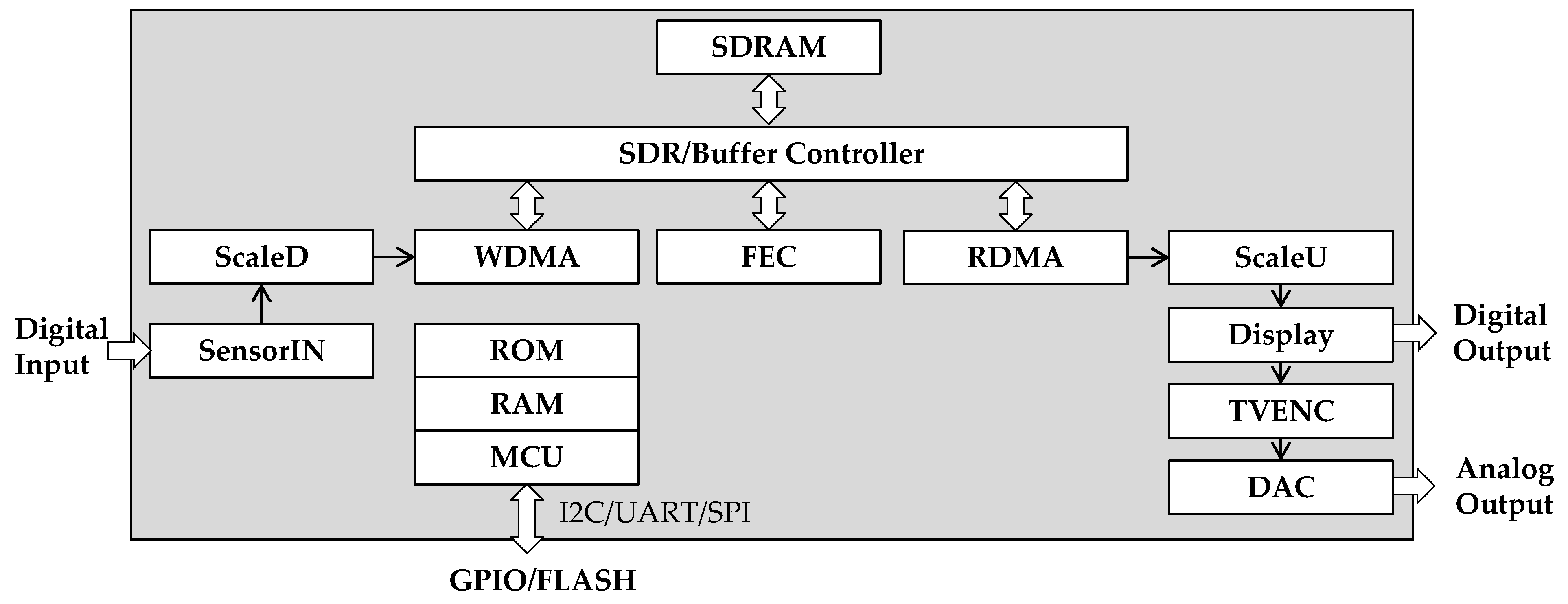
In order to integrate the system of multiple chips, the IPC provides multiple input and output formats, image scale-up and scale-down, wide-angle image distortion correction, image buffer controller and TV encoder. The function block diagram of IPC is shown in Figure 3. The sensor input block (SensorIN) is responsible for extracting input image data according to the separated synchronous signals (SYNC) or embedded SYNC format. The scale-down block (ScaleD) is responsible for scaling the image down. The scale-up block (ScaleU) is responsible for scaling the image up. The fish-eye correction block (FEC) is responsible for wide-angle image distortion correction. The image buffer of the SDRAM controller (SDR/Buffer) is responsible for delaying the writing and reading of image data into and from SDRAM. The write-type direct memory access block (WDMA) and the read-type direct memory access block (RDMA) are responsible for writing and reading image data into and from SDRAM through the SDR/Buffer controller interface, respectively. The display block (Display) is responsible for outputting digital images in separated SYNC or embedded SYNC formatted according to the settings. The TV encoder block (TVENC) is responsible for converting the digital image into a TV digital signal according to the BT656/BT1120 specification. Finally, the digital to analog converter block (DAC) is responsible for converting the TV digital signal into an analog video signal. It is worth mentioning that the microprocessor (MCU) with RAM and ROM can set the function module according to the image size and functional requirements.

2.3.1. The I/O Data Format of the IPC

Since the input and output data formats of multiple chips are different when integrating PCB, the IPC supports input and output formats such as separated SYNC and embedded SYNC to improve integration integrity and convenience. In addition to the image data, the image signal in the separated SYNC format also has additional synchronization signals such as VSYNC and HSYNC to distinguish images of different frames and the data of different horizontal scan lines in the same frame, respectively. Therefore, when using separated SYNC for the connection between the chips on the PCB, the increased width of the bus implies a bigger PCB area. The embedded SYNC is different from separate SYNC in that the synchronization signal is inserted in the blank interval between the image signals. Therefore, when embedded SYNC is selected for the connection between the chips on the PCB, as long as decoding embedded SYNC, not only the blanking and active video intervals can be distinguished from the video stream but also the data can be extracted from the Active Video. When Embedded SYNC is selected for the connection between chips, the bit width of the bus can be reduced due to the bus does not contain synchronization signals. Choosing embedded SYNC has an advantage for reducing PCB size.

2.3.2. Wide-Angle Image Distortion Correction

The AI model usually uses non-distortion images in public data sets for training. Oppositely, the image captured by the wide-angle rear-view camera often has distortion. Therefore, wide-angle image correction technology must be used to correct the image distortion to avoid reducing the detection rate, before using artificial intelligence object detection. The wide-angle image distortion correction we designed is to establish the coordinate conversion between the distorted image and the not distorted image. As shown in Figure 4, the image of the sensor chip is regarded as a plane and the image of the wide-angle lens is regarded as a hemispherical plane.
In Figure 4, P represents the point on a wide-angle curved surface with the coordinates (px, py); P′ represents the point on the corrected image with coordinates (px′, py′); r represents the distance between the corrected image coordinates and the origin of the corrected coordinates; Radius represents the distance from (px, py) to the origin of the wide-angle image; F represents the focal length of the wide-angle lens. The arctan() and arctan2() are used to calculate the angle values of φ and θ, respectively. The conversion relationship between the surface of the wide-angle lens and the imaging plane can be established through the following Formulas (1)–(5).
r = ( p x ) 2 + ( p y ) 2 ,
φ = arctan 2 ( p y / p x ) ,
θ = arctan ( r / F ) ,
R a d i u s = F · θ ,
( p x , p y ) = ( R a d i u s · cos ( φ ) , R a d i u s · sin ( φ ) )
The pixel value of the coordinate (px′, py′) is obtained by interpolating the pixel value of the adjacent coordinate point near the coordinate (px, py). The relationship which indicates before and after the processing of the wide-angle distortion correction is shown in Figure 5.

2.3.3. Image Buffer Controller

The KL520 of the reversing camera system is used to calculate the type and coordinates of the object and then outputs to the second IPC. Since KL520 takes time to calculate, the calculated coordinate values will not correspond to the frames in the original image stream correctly, as shown in Figure 6. That is why we design the image buffer controller in the IPC. The function of the image buffer controller is to control the memory block to temporarily store multiple frames of images. Until the pre-set number of temporarily stored images, the stored images are sequentially outputted from the first frame of temporarily stored images. By using the image buffer controller, we can make sure that the bounding boxes of the objects are on the corresponding frame. As shown in Figure 7, the object coordinates calculated in the nth frame should correspond to the nth frame image.

2.3.4. TV Encoder

The IPC we designed includes a TV encoder. By programming the parameters of the TV encoder such as the image width and height, the output of IPC supports 720P 30 fps and 1080P 30 fps. Since the color signal of the analog video is modulated by frequency and synthesized into the luminance signal, the subcarrier frequency of modulation must be accurate. Through the built-in look-up tables of sine and cosine value of the TV encoder, we can not only generate the subcarrier waveform in time but also make the subcarrier frequency more accurate. In addition, we designed the TV encoder to dynamically adjust the Color Burst amplitude and to provide four color saturation of 25%, 50%, 75% and 100%.

2.4. The Artificial Intelligence Model

2.4.1. The Selection of the Artificial Intelligence Network

We set Tiny_YOLOV3 as the basic structure at the beginning of planning the artificial intelligence network. However, during the development process, it was found that the object detection model using Tiny_YOLOV3 could not meet the requirements of real-time, as shown in Figure 8a. Therefore, we merged Tiny_YOLOV3 and MobileNetV2 as the basic architecture of the artificial intelligence network named MobileNetV2-YOLOV3, as shown in Figure 8b. This network architecture uses depth-wise convolution instead of general convolution, so the calculations can be greatly reduced. At the same time, the transmission bandwidth of the network in the calculation process is relatively small. We focus on reducing calculations and parameters and achieving real-time requirements. In order to improve the multi-scale detection of various objects, we use two detector anchors in the network architecture of MobileNetV2-YOLOV3. In the middle of the two sets of anchors of different sizes, we use a convolution layer to replace the up-sampling layer to reduce the calculations and avoid the waste of time caused by AI chips using the CPU to transfer data. We consider that the use of a convolution layer instead of an up-sampling layer can avoid the waste of time caused by AI chips using the CPU to transfer data, but it may cause the accuracy of object detection to decrease. For this problem, we imported additional training techniques such as GIOU [40], in an attempt to improve the accuracy of object detection. After a series of modifications and optimizations, we finally named this artificial intelligence network MobileNetV2-YOLOV3-Optimized (MNYLO).

2.4.2. Image Labeling, Training and Testing

We use not only the category images related to people and cars in the VOC2007 data set but also an additional 40,000 images captured by the rear-view camera as the source of training images in order to have a good training result. In order to make the results of AI training have universality, these additional collected images are distributed in different scenes, as shown in Table 2 for details. We adopt supervised learning for the collected 40,000 images database and the VOC2007 data sets related to people and vehicles. We follow the rule of using 95% of all images as training images and the other 5% of images as test images.

3. Results

We use the first IPC to handle input image format conversion and image distortion correction, and select appropriate AI chips KL520 to run the tasks of artificial intelligence objects detection. Through the second IPC, the coordinates of the recognized object are converted and bounding boxes are added. Finally, the user gets the final analog video by pre-setting the TV encoder parameters. In this section, we will describe the verification result of the carefully designed image processing chip one by one, including the wide-angle image distortion correction function, the image buffer controller function, and the subcarrier frequency of the TV encoder. Furthermore, we record the performance of the optimized artificial intelligence model and the power consumption of the reversing camera system.

3.1. Wide-Angle Image Distortion Correction

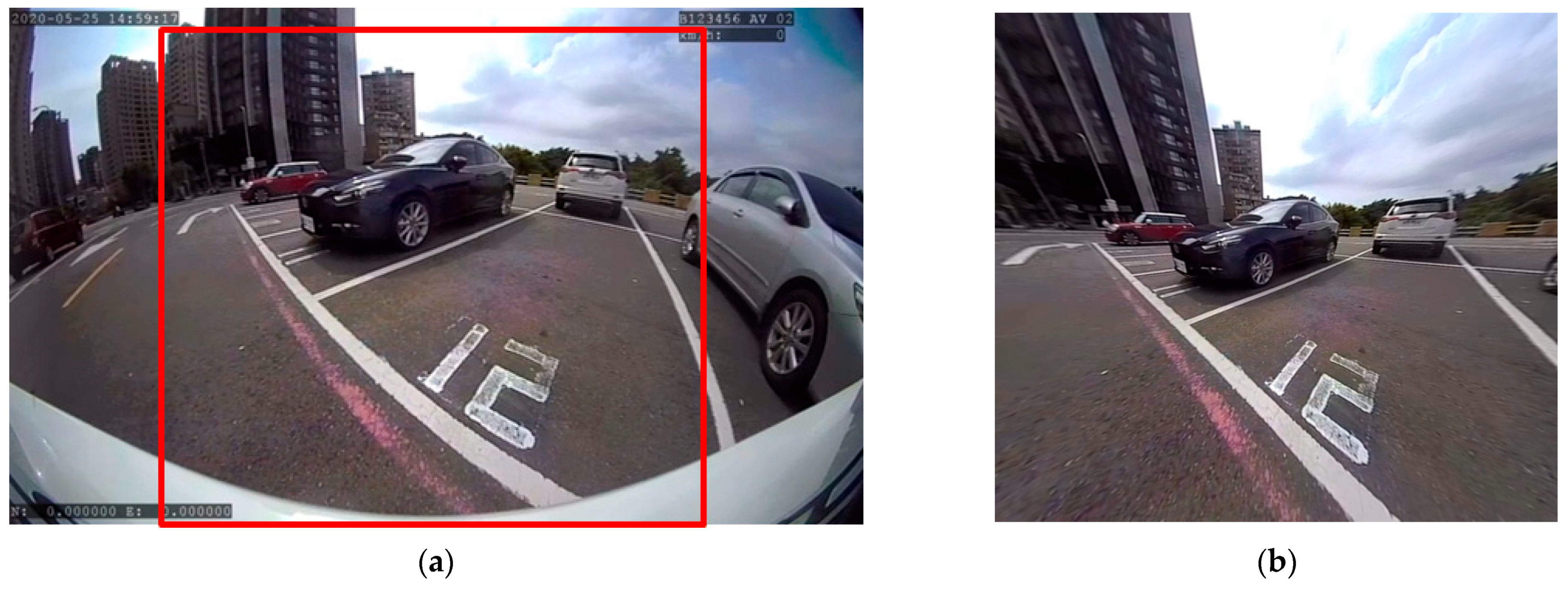
We verify the wide-angle image distortion correction of the IPC. The wide-angle image distortion correction corrects the distorted image captured by the wide-angle lens. The actual test results are shown in Figure 9. Figure 9a is a distorted image captured by a wide-angle lens. Figure 9b is the result of distortion correction of the image in the red area of Figure 9a. Obviously, the result of the wide-angle image distortion correction is good and can provide a good image for the AI chip to perform object detection.

3.2. Image Buffer Controller

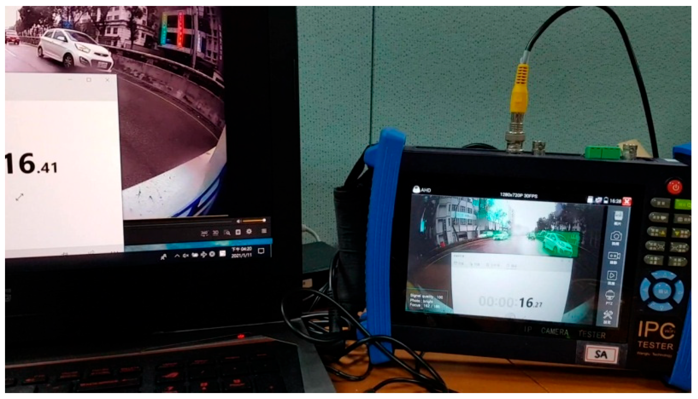
Since the second IPC receives the coordinates of the object detection by the KL520 chip and then converts them into the coordinates in the original image, it is sure that time delay occurs. We had to perform an additional experiment to get the delay time for the calculation of coordination by AI chip. We used the camera to capture the time of the stopwatch on the PC screen and observed the time required for the KL520 chip to calculate the coordinates of the objects. It can be seen from Figure 10 that the time of objects detection is about 16.41 s − 16.27 s = 140 ms. Since the time for one frame of 720P 30 fps video is 33.33 ms, we set the image buffer controller of the second IPC to achieve a 4-frame delay for the input video, that is a delay of 4 × 33.33 ms = 133.32 ms. The 4-frame delay makes the coordinates of the recognized object calculated by the KL520 chip correctly correspond to the position of the image of the corresponding frame.

3.3. TV Encoder

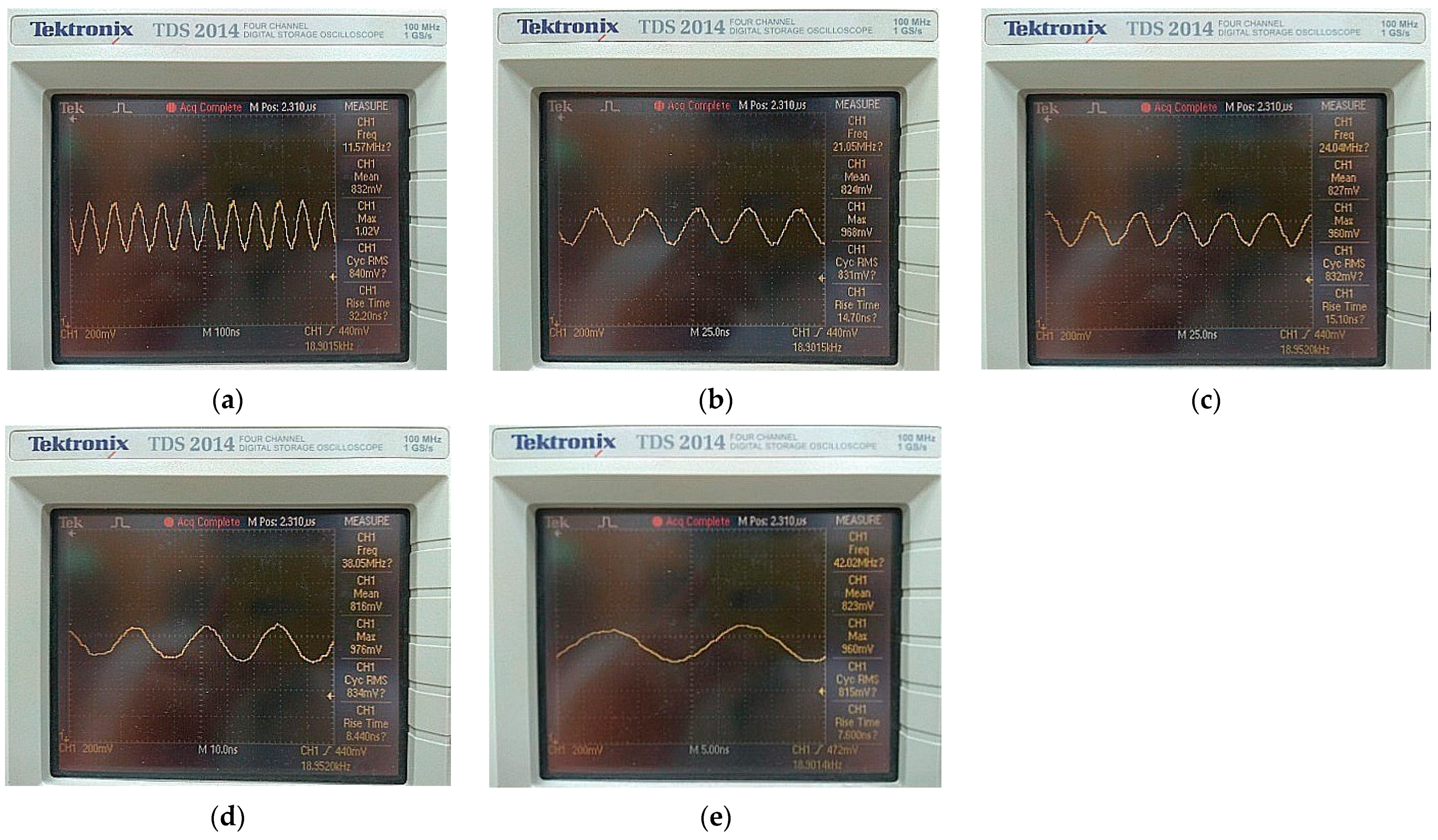
The TV encoder of the IPC we designed can output a resolution and frame rate of up to 1080P 30 fps. Since the color signal is modulated and synthesized into the brightness signal of video, the subcarrier frequency used during modulation needs to be accurate. We tested various common subcarrier frequencies. The result of the measurement is shown in Figure 11. The measured result is organized and shown in Table 3 below. In Table 3, we compared the subcarrier frequency generated by the TV encoder of the IPC and the expected measurement frequency, the maximum error rate of all cases is <0.3%, so it can be guaranteed to be demodulated by the receiving device and restored to the original color and brightness.
In addition, we also verified that the TV encoder we designed can adjust four color burst amplitudes to satisfy four color saturation, as shown in Figure 12.

3.4. The Performance of the Artificial Intelligence Model

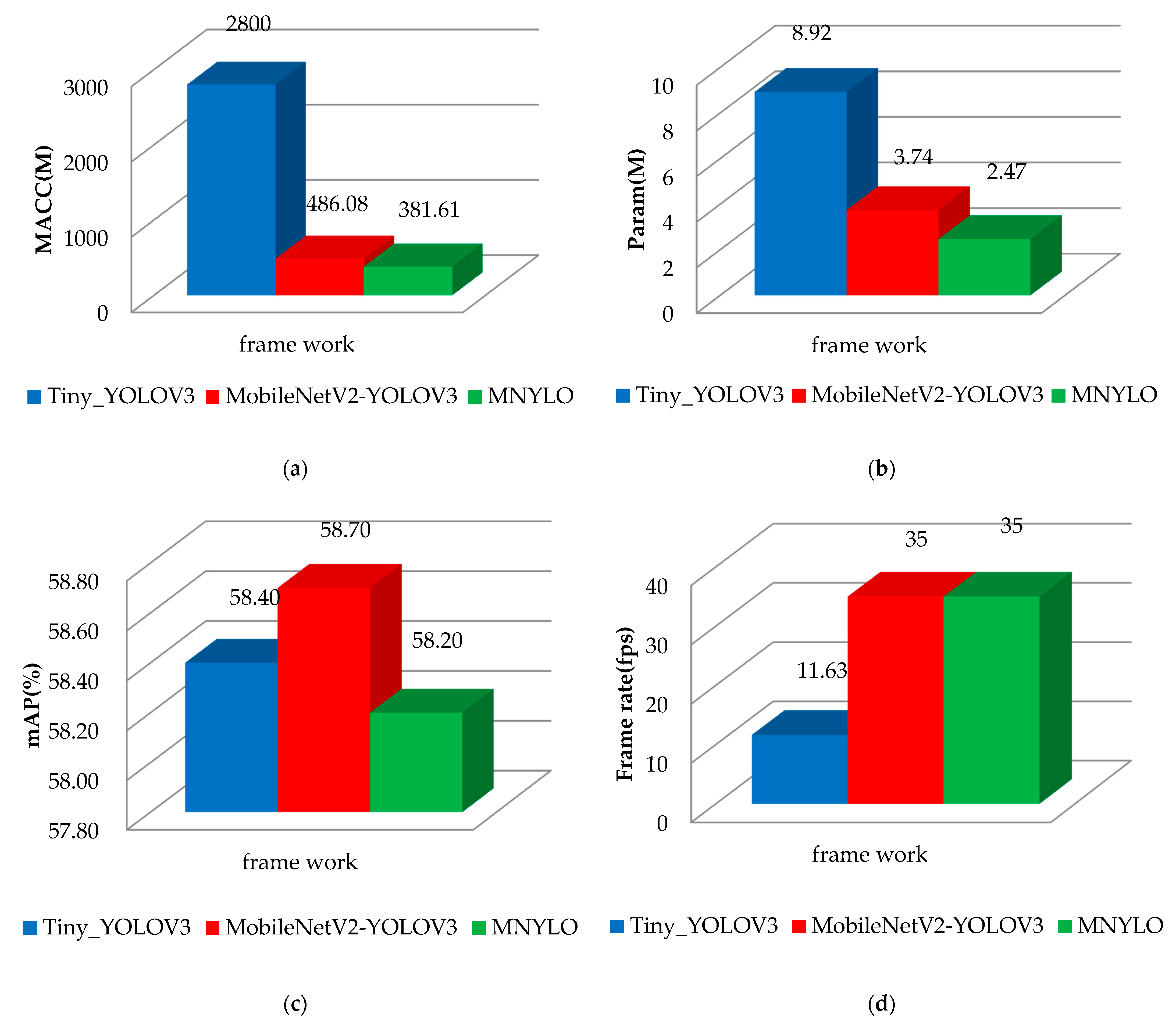
In order to make the operation of the reversing camera system meet the requirements of real-time, we optimized the artificial intelligence model by reducing the calculations and the parameters. In order to save energy for the entire reversing camera system, we choose the KL520 as an AI chip, which consumes low power and has suitable computing capabilities. In order to improve the accuracy of object detection in the AI model, we use additional training techniques such as intersection over union (IoU) threshold and generalized intersection over union (GIOU). Finally, we use the VOC2007 dataset and various scene images collected by ourselves for model training and testing. The results of object detection accuracy are organized and shown in Table 4 and Figure 13.
We compare three AI models, namely Tiny_YOLOV3, MobileNetV2-YOLOV3 and MobileNetV2-YOLOV3-Optimized (MNYLO) in Table 4. The Tiny_YOLOV3 is the baseline for the entire test. The MobileNetV2-YOLOV3 is the AI model obtained by using MobileNetV2 as the framework and using the convolution layer to replace the up-sampling layer in the process of optimizing the AI model. The MNYLO is our final version of the AI model that continues MobileNetV2-YOLOV3 and further uses pruning technology to improve the accuracy of object detection.
The multiply-accumulate operations (MACC) in Table 4 points out the calculations of the AI models. The larger the MACC is, the higher the calculations required. In order to meet the larger MACC and achieve real-time computing, the AI chip with more powerful computing capabilities is required. In Table 4, the parameter (Param) represents the amount of parameters required by the AI model. The larger the amount of parameters, the more calculation and storage space the entire AI model needs during the training and computing. In Table 4, the mean average precision (mAP) represents the average accuracy of object detection. The higher the mAP is, the more accurate the coordinate position of the recognized object is. In Table 4, the frame rate is used to indicate whether the performance of the AI models can meet the requirements of real-time (more than 30 fps).
From Table 4, our final AI model, MNYLO, compared to Tiny_YOLOV3 reduces the calculations by 86.37% in the MACC item and reduces parameters by 72.30% in the Param item. In the mAP item, our final AI model, MNYLO is less than the Tiny_YOLOV3 by 0.2%. According to the comprehensive comparison, the MNYLO model has greatly reduced the amount of calculation and parameters and maintained the accuracy of object detection. This means that the MNYLO model has successfully achieved real-time object detection on a lower power consumption artificial intelligence chip.
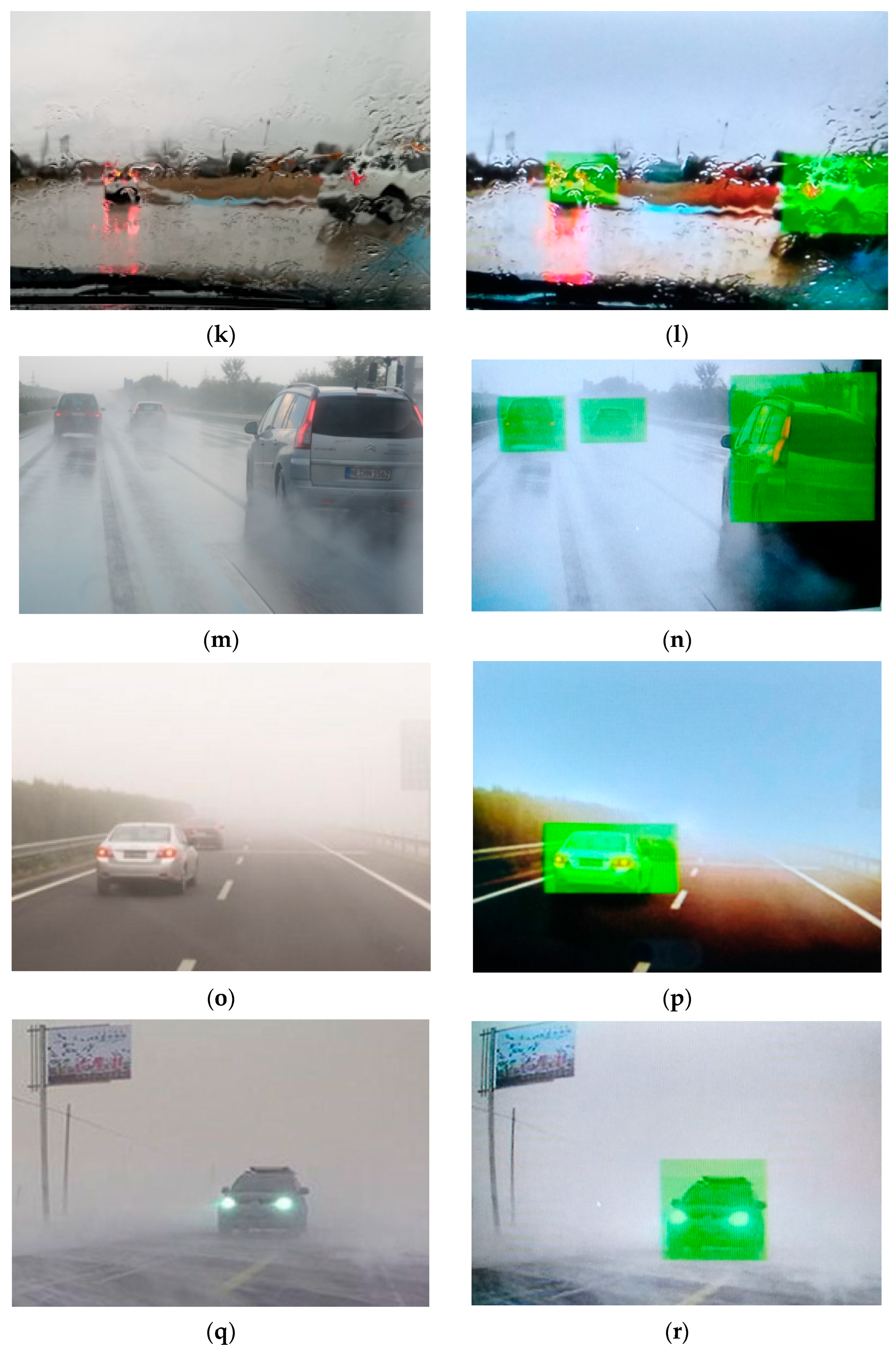
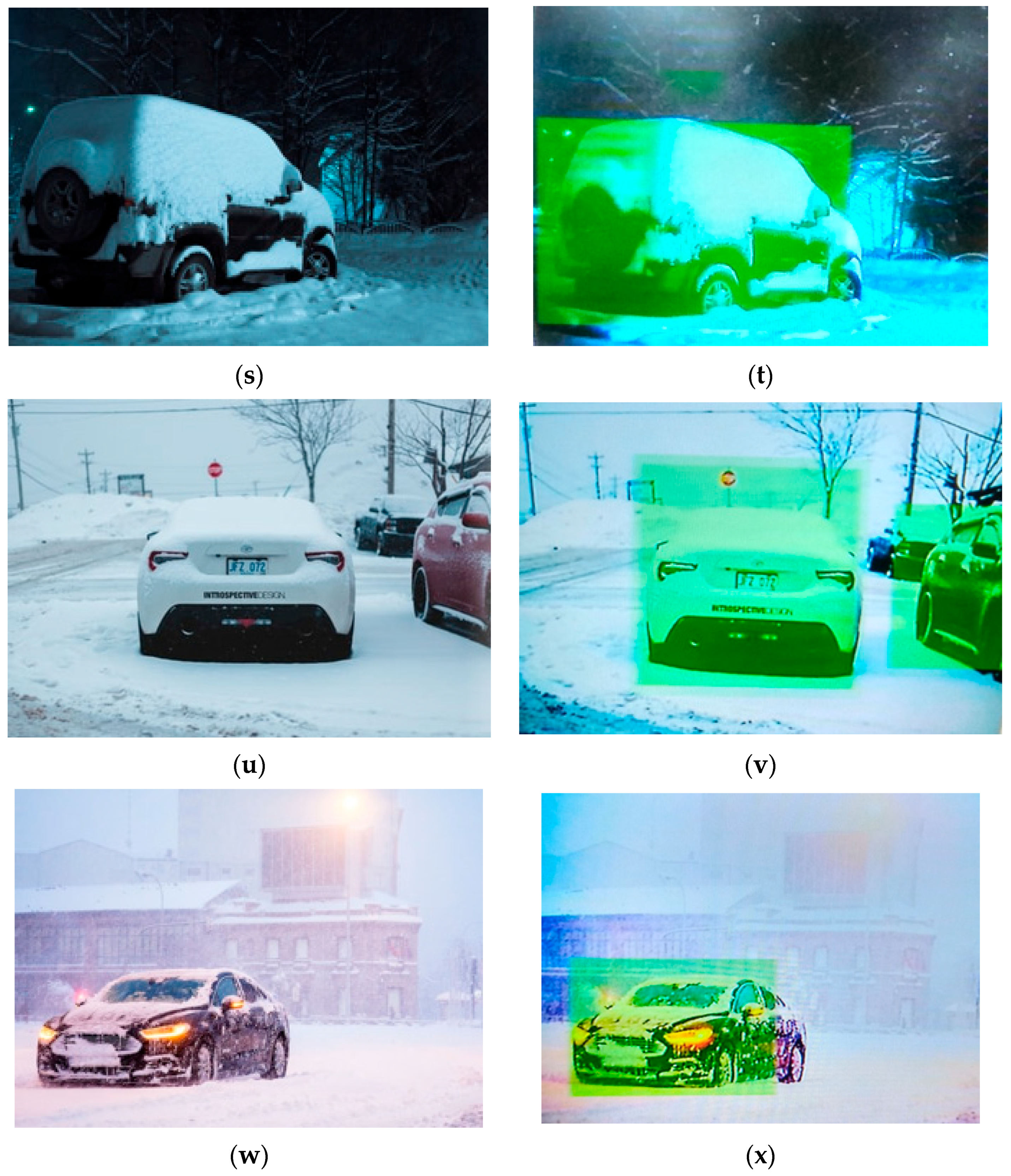
At the end phase of verification, we use the reversing camera system to output the video, as shown in Figure 14. In Figure 14, we programmed the reversing camera system to use green, red, yellow and white masks to mark the area where vehicles, trucks, people and bikes are recognized, respectively.

3.5. The Power Consumption of the Reversing Camera System

Furthermore, we measured the current consumption of the entire system which includes a PR2000 chip, an ARM STM32F103, two IPCs, a KL520 chip and two flash memory chips. We used the power supply providing 12 V voltage and measured the current consumption of the entire system as 160 mA. The operating power of the reversing camera system is 1.920 watts. We not only pay attention to the accuracy of object detection but also the power consumption of the system. The camera module of the reversing camera system is placed outside the car and connected to the display screen placed in the car through a coaxial cable. The size of the commercially available camera module is approximately 30 mm × 30 mm × 30 mm. Optical lenses, image sensor chips, image processing chips, artificial intelligence computing chips and other related electronic components need to be placed in such a volume. A camera module of this size must have sufficient heat dissipation capacity. If the heat generated by the image sensor chip, the image processing chip, and the artificial intelligence computing chip cannot be effectively dissipated, the heat will be accumulated in the camera module and cause the temperature to rise. When the temperature of the camera module exceeds 85 degrees Celsius, the image sensor chip gradually produces thermal noise, image flickering, and color changes. However, the contaminated images caused by these problems cannot be restored with the image processing chip and will cause the artificial intelligence computing chip to fail to detect objects. Due to the size of the camera module, the maximum heat dissipation capacity is limited. Therefore, to avoid contaminated images caused by heat accumulation, the most effective way is to reduce the heat generation of the entire system. The best way to reduce the heat generation of the system is to use low-power components. Our reversing camera system has no problems of thermal noise, image flickering, and color changes.

4. Discussion

According to the results in Table 4, the reversing camera system with artificial intelligence object detection we have implemented has the biggest advantage in object detection is that compared to Tiny_YOLOV3, the MNYLO reduces the calculations by 86.37% in the MACC item and reduces parameters by 72.30% in the Param item. The first benefit is to achieve the implementation of artificial intelligence in real-time image transmission. The second benefit is that there is no need for a high-energy-consuming graphics card and the whole system with low power consumption can be achieved. In terms of image transmission, our biggest advantage is the powerful function of correcting distorted images, so we can use public training data sets. Furthermore, it is not necessary to exclude curved lenses when collecting special scenarios image datasets.
Figure 14 shows that our system can present excellent object detection results in rainy, foggy, and snowy weather, as well as the general weather. We confirm the hypothesis of this article. It is possible to train the optimized artificial intelligence network in multiple scenarios to replace the specific algorithms necessary to eliminate specific weather conditions.
In addition, we found three important points. Firstly, to have a high detection rate of artificial intelligence object detection, the system must have a powerful image processing chip to correct distorted images and a lightweight optimized artificial intelligence network to detect objects. Secondly, to achieve the requirement of real-time objects detection, the system must have both a lightweight optimized artificial intelligence network and an artificial intelligence edge computing chip with sufficient computing power. Thirdly, to meet the requirements of low power consumption, the system must have both a powerful image processing chip and an artificial intelligence edge computing chip with appropriate computing power. Since the three important points above, we are convinced that for our system, the reason for the success of having both the high object detection rate and low power consumption at the same time is to have an image processing chip with real-time computing capability, a lightweight artificial intelligence network, and an artificial intelligence chip with the appropriate computing power.

5. Conclusions

By integrating two self-designed IPCs, an AI chip Keneron-KL520 with appropriate computing power but low power and an optimized AI model MNYLO, we implement a reversing camera system with artificial intelligence object detection. The self-designed IPC has four main functions. First, the IPC supports a variety of input and output formats including separated SYNC and embedded SYNC. Second, the IPC supports wide-angle image distortion correction, which can correct distorted input images captured by wide-angle lens. Third, the IPC has an image buffer controller which can control the input image to achieve a delay of multiple image frames. Fourth, the IPC has an accurate subcarrier frequency which is generated by looking up the sine and cosine table. We use the AI edge computing chip Keneron-KL520 to run the optimized AI model MNYLO to realize real-time object detection.
Based on a single visual aid, for reversing, our system provides more visual information such as objects detection. Our system can replace the algorithms which are used to eliminate bad weather such as raining, fogging, or snowing weather. Whether it is raining, fogging, or snowing, our system can show excellent robust performance as in normal weather. The existing reversing camera systems which are connected to our system can be easily upgraded and have the function of artificial intelligence object detection right away. It is satisfactory that the power consumption of the entire system is <2 watts. Undoubtedly, our reversing camera system provides a solution that takes into account intelligence, safety and energy saving for commercially available reversing camera systems.

Author Contributions

Conceptualization, M.-C.L.; Methodology, M.-C.L. and K.-C.H.; validation, M.-C.L. and K.-C.H.; writing—original draft preparation, K.-C.H. and S.-F.L.; writing—review and editing, K.-C.H. All authors have read and agreed to the published version of the manuscript.

Funding

This research received no external funding.

Acknowledgments

We would like to give thanks for the technical support of Avisonic partners. Thanks to the help of the above friends, this reversing camera system with artificial intelligence object detection could be completed smoothly.

Conflicts of Interest

The authors declare no conflict of interest.

References

  1. Global Status Report on Road Safety. 2015. Available online: https://www.afro.who.int/publications (accessed on 6 October 2021).
  2. Preventing Driveway Tragedies: Rear Cameras Help Drivers See What’s Going on behind Them. Available online: https://www.iihs.org/api/datastoredocument/status-report/pdf/49/2 (accessed on 6 October 2021).
  3. Park, J.; Byun, S.-C.; Lee, B.-U. Lens distortion correction using ideal image coordinates. IEEE Trans. Consum. Electron. 2009, 55, 987–991. [Google Scholar] [CrossRef]
  4. Wei, J.; Li, C.-F.; Hu, C.-M.; Martin, R.R.; Tai, C.-L. Fisheye Video Correction. IEEE Trans. Vis. Comput. Graph. 2012, 18, 1771–1783. [Google Scholar] [CrossRef] [PubMed] [Green Version]
  5. Park, J.; Lee, B.-U. Lens Distortion Correction of images with Gradient Components. J. Inst. Electron. Inf. Eng. 2013, 50, 231–235. [Google Scholar] [CrossRef]
  6. Li, J.; Su, J.; Zeng, X. A solution method for image distortion correction model based on bilinear interpolation. Comput. Opt. 2019, 43, 99–104. [Google Scholar] [CrossRef]
  7. He, Y.; Xiong, W.; Chen, H.; Chen, Y.; Dai, Q.; Tu, P.; Hu, G. Fish-Eye Image Distortion Correction Based on Adaptive Partition Fitting. Comput. Model. Eng. Sci. 2021, 126, 379–396. [Google Scholar] [CrossRef]
  8. Weng, J.; Zhou, W.; Ma, S.; Qi, P.; Zhong, J. Model-Free Lens Distortion Correction Based on Phase Analysis of Fringe-Patterns. Sensors 2020, 21, 209. [Google Scholar] [CrossRef] [PubMed]
  9. You, S.; Tan, R.; Rei, K.; Makaigawa, Y.; Ikeuchi, K. Raindrop Detection and Removal from Long Range Trajectories. In Proceedings of the ACCV 2014: Asian Conference on Computer Vision, Singapore, 1–5 November 2014. [Google Scholar]
  10. Qian, R.; Tan, R.T.; Yang, W.; Su, J.; Liu, J. Attentive Generative Adversarial Network for Raindrop Removal from a Single Image. In Proceedings of the IEEE Conference on Computer Vision and Pattern Recognition, Salt Lake City, UT, USA, 18–23 June 2018; pp. 2482–2491. [Google Scholar]
  11. Zhang, H.; Patel, V.M. Density-aware single image de-raining using a multi-stream dense network. In Proceedings of the IEEE Conference on Computer Vision and Pattern Recognition, Salt Lake City, UT, USA, 18–23 June 2018; pp. 695–704. [Google Scholar]
  12. Ren, D.; Zuo, W.; Hu, Q.; Zhu, P.; Meng, D. Progressive image deraining networks: A better and simpler baseline. In Proceedings of the IEEE/CVF Conference on Computer Vision and Pattern Recognition, Long Beach, CA, USA, 16–20 June 2019; pp. 3937–3946. [Google Scholar]
  13. Al Machot, F.; Ali, M.; Haj Mosa, A.; Schwarzlmüller, C.; Gutmann, M.; Kyamakya, K. Real-time raindrop detection based on cellular neural networks for ADAS. J. Real-Time Image Process. 2016, 16, 931–943. [Google Scholar] [CrossRef] [Green Version]
  14. Luo, H.; Wu, Q.; Ngan, K.N.; Luo, H.; Wei, H.; Li, H.; Meng, F.; Xu, L. Multi-Scale Shape Adaptive Network for Raindrop Detection and Removal from a Single Image. Sensors 2020, 20, 6733. [Google Scholar] [CrossRef] [PubMed]
  15. Li, X.; Zhang, B.; Liao, J.; Sander, P. Let’s See Clearly: Contaminant Artifact Removal for Moving Cameras. arXiv 2021, arXiv:2104.08852. [Google Scholar]
  16. Deshmukh, A.; Singh, S.; Singh, B. Design and development of image defogging system. In Proceedings of the 2016 International Conference on Signal and Information Processing (IConSIP), Nanded, India, 6–8 October 2016; pp. 1–5. [Google Scholar]
  17. Engin, D.; Genç, A.; Kemal Ekenel, H. Cycle-dehaze: Enhanced cyclegan for single image dehazing. In Proceedings of the IEEE Conference on Computer Vision and Pattern Recognition Workshops, Salt Lake City, UT, USA, 18–22 June 2018; pp. 825–833. [Google Scholar]
  18. Qu, Y.; Chen, Y.; Huang, J.; Xie, Y. Enhanced pix2pix dehazing network. In Proceedings of the IEEE/CVF Conference on Computer Vision and Pattern Recognition, Long Beach, CA, USA, 16–20 June 2019; pp. 8160–8168. [Google Scholar]
  19. Tufail, Z.; Khurshid, K.; Salman, A.; Khurshid, K. Optimisation of transmission map for improved image defogging. IET Image Process. 2019, 13, 1161–1169. [Google Scholar] [CrossRef]
  20. Fan, D.; Guo, X.; Lu, X.; Liu, X.; Sun, B. Image Defogging Algorithm Based on Sparse Representation. Complexity 2020, 2020, 6835367. [Google Scholar] [CrossRef]
  21. Gao, T.; Li, K.; Chen, T.; Liu, M.; Mei, S.; Xing, K.; Li, Y.H. A Novel UAV Sensing Image Defogging Method. IEEE J. Sel. Top. Appl. Earth Obs. Remote Sens. 2020, 13, 2610–2625. [Google Scholar] [CrossRef]
  22. Anan, S.; Khan, M.I.; Kowsar, M.M.S.; Deb, K.; Dhar, P.K.; Koshiba, T. Image Defogging Framework Using Segmentation and the Dark Channel Prior. Entropy 2021, 23, 285. [Google Scholar] [CrossRef] [PubMed]
  23. Graffieti, G.; Maltoni, D. Artifact-Free Single Image Defogging. Atmosphere 2021, 12, 577. [Google Scholar] [CrossRef]
  24. Xu, S.; Fu, Y.; Sun, X. Single Image Defogging Algorithm Based on Sky Region Segmentation. J. Phys. Conf. Ser. 2021, 1971, 012068. [Google Scholar] [CrossRef]
  25. A Flexible Architecture for Fisheye Correction in Automotive Rear-View Cameras; AFA: Salt Lake City, UT, USA, 1998; Available online: http://www.manipal.net/mdn/technology/fisheye_correction.pdf (accessed on 15 January 2022).
  26. Tadjine, H.; Hess, M.; Karsten, S. Object Detection and Classification Using a Rear In-Vehicle Fisheye Camera. In Proceedings of the FISITA 2012 World Automotive Congress; Springer: Berlin/Heidelberg, Germany, 2012; Volume 197, pp. 519–528. [Google Scholar]
  27. Wu, Y.; Li, J.; Yuan, Y.; Qin, A.; Miao, Q.-G.; Gong, M.-G. Commonality Autoencoder: Learning Common Features for Change Detection from Heterogeneous Images. IEEE Trans. Neural Netw. Learn Syst. 2021, 1–14. [Google Scholar] [CrossRef] [PubMed]
  28. Wu, Y.; Ma, W.; Gong, M.; Su, L.; Jiao, L.J.I.G.; Letters, R.S. A novel point-matching algorithm based on fast sample consensus for image registration. IEEE Geosci. Remote Sens. Lett. 2014, 12, 43–47. [Google Scholar] [CrossRef]
  29. Krizhevsky, A.; Sutskever, I.; Hinton, G.E. Imagenet classification with deep convolutional neural networks. Adv. Neural Inf. Process. Syst. 2012, 25, 1097–1105. [Google Scholar] [CrossRef]
  30. Szegedy, C.; Liu, W.; Jia, Y.; Sermanet, P.; Reed, S.; Anguelov, D.; Erhan, D.; Vanhoucke, V.; Rabinovich, A. Going deeper with convolutions. In Proceedings of the IEEE Conference on Computer Vision and Pattern Recognition, Boston, MA, USA, 7–12 June 2015; pp. 1–9. [Google Scholar]
  31. Simonyan, K.; Zisserman, A. Very deep convolutional networks for large-scale image recognition. In Proceedings of the International Conference on Learning Representations, Banff, AB, Canada, 14–16 April 2014. [Google Scholar]
  32. He, K.; Zhang, X.; Ren, S.; Sun, J. Deep residual learning for image recognition. In Proceedings of the IEEE Conference on Computer Vision and Pattern Recognition, Las Vegas, NV, USA, 26 June–1 July 2016; pp. 770–778. [Google Scholar]
  33. Szegedy, C.; Vanhoucke, V.; Ioffe, S.; Shlens, J.; Wojna, Z. Rethinking the inception architecture for computer vision. In Proceedings of the IEEE Conference on Computer Vision and Pattern Recognition, Las Vegas, NV, USA, 26 June–1 July 2016; pp. 2818–2826. [Google Scholar]
  34. Szegedy, C.; Ioffe, S.; Vanhoucke, V.; Alemi, A.A. Inception-v4, inception-resnet and the impact of residual connections on learning. In Proceedings of the Thirty-First AAAI Conference on Artificial Intelligence, San Francisco, CA, USA, 4–9 February 2017. [Google Scholar]
  35. Canziani, A.; Paszke, A.; Culurciello, E. An analysis of deep neural network models for practical applications. arXiv 2016, arXiv:1605.07678. [Google Scholar]
  36. Analysis of Deep Neural Networks. Available online: https://culurciello.medium.com/analysis-of-deep-neural-networks-dcf398e71aae (accessed on 8 October 2021).
  37. NVIDIA. Available online: https://www.nvidia.com/ (accessed on 8 October 2021).
  38. List of Nvidia Graphics Processing Units. Available online: https://en.wikipedia.org/wiki/List_of_Nvidia_graphics_processing_units8 (accessed on 8 October 2021).
  39. Howard, A.G.; Zhu, M.; Chen, B.; Kalenichenko, D.; Wang, W.; Weyand, T.; Andreetto, M.; Adam, H. Mobilenets: Efficient convolutional neural networks for mobile vision applications. arXiv 2017, arXiv:1704.04861. [Google Scholar]
  40. Zheng, Z.; Wang, P.; Liu, W.; Li, J.; Ye, R.; Ren, D. Distance-IoU loss: Faster and better learning for bounding box regression. In Proceedings of the AAAI Conference on Artificial Intelligence, New York, NY, USA, 7–12 February 2020; pp. 12993–13000. [Google Scholar]
Figure 1. The power consumption of various common Graphic cards [37,38].
Electronics 11 00282 g001
Figure 2. The architecture of the reversing camera system of this paper.
Electronics 11 00282 g002
Figure 3. The function block diagram of the IPC.
Electronics 11 00282 g003
Figure 4. The Conversion relationship from the wide-angle curved surface to the corrected image plane. By finding 4 parameters such as r, φ, θ and F, we can establish the mapping relationship formula between any point on the wide-angle image distortion plane and any point on the corrected image plane.
Electronics 11 00282 g004
Figure 5. The simulation result of the wide-angle distortion correction: (a) before the wide-angle image distortion correction; (b) after the wide-angle image distortion correction.
Electronics 11 00282 g005
Figure 6. Without the buffer controller, the object coordinates calculated by the AI chip do not match the current image frame.
Electronics 11 00282 g006
Figure 7. With the buffer controller, the object coordinates calculated by the AI chip match the current image frame.
Electronics 11 00282 g007
Figure 8. The comparison of the architecture of the artificial intelligence models: (a) using Tiny_YOLOV3 as the backbone; (b) Merge Tiny_YOLOV3 and Mobile-Net V2 as the backbone.
Electronics 11 00282 g008
Figure 9. The test results of wide-angle image distortion correction: (a) the distorted image captured by wide-angle lens; (b) after correcting the distorted image corresponding to the red area.
Electronics 11 00282 g009
Figure 10. The computing time of AI chips.
Electronics 11 00282 g010
Figure 11. The test results of wide-angle image distortion correction: (a) Measured Subcarrier Freq. = 11.57 MHz in case 1; (b) Measured Subcarrier Freq. = 21.05 MHz in case 2; (c) Measured Subcarrier Freq. = 24.04 MHz in case 3; (d) Measured Subcarrier Freq. = 38.05 MHz in case 4; (e) Measured Subcarrier Freq. = 42.02 MHz in case 5.
Electronics 11 00282 g011
Figure 12. TV encoder provides four color burst amplitudes: (a) color bar with 25% amplitude; (b) color bar with 50% amplitude; (c) color bar with 75% amplitude; (d) color bar with 100% amplitude.
Electronics 11 00282 g012
Figure 13. The comparison of artificial intelligence models: (a) the MACC; (b) the parameters; (c) the mAP; (d) the frame rate.
Electronics 11 00282 g013
Figure 14. The original images and the result images outputted by our reversing camera system: (a) The original image with scooters; (b) Our result image with scooters; (c) The original image with a truck; (d) Our result image with a truck; (e) The original image with vehicles; (f) Our result image with vehicles; (g) The original image with people; (h) Our result image with people; (i) The original image on a rainy day; (j) Our result image on a rainy day; (k) The original image on a rainy day; (l) Our result image on a rainy day; (m) The original image on a rainy day; (n) Our result image on a rainy day; (o) The original image on a foggy day; (p) Our result image on a foggy day; (q) The original image on a snowy day; (r) Our result image on a snowy day; (s) The original image at snowy night; (t) Our result image at snowy night; (u) The original image on a snowy day; (v) Our result image on a snowy day; (w) The original image on a snowy day; (x) Our result image on a snowy day.
Electronics 11 00282 g014aElectronics 11 00282 g014bElectronics 11 00282 g014c
Table 1. The summary of some well-known AI models.
AI ModelParametersTop-5 Error
AlexNet [29]60 MB15.3%
GoogleNet [30]4 MB6.67%
VGG Net [31]138 MB7.3%
ResNet [32]60 MB3.57%
Table 2. The training images of different scenes.
The Main SceneThe 1th Sub-SceneThe 2nd Sub-SceneNumber of Images
On the roaddaytimeRainy day5000 pics
Non-rainy day5000 pics
nighttimeRainy day5000 pics
Non-rainy day5000 pics
In the parking lotoutdoorNighttime5000 pics
Nighttime5000 pics
indoorBright ambient light5000 pics
Dim ambient light5000 pics
Table 3. The measurement of subcarrier frequency.
ItemCase 1Case 2Case 3Case 4Case 5
Resolution720P 1720P 11080P 21080P 21080P 2
Frame rate (fps)30 fps30 fps30 fps30 fps30 fps
Defined Subcarrier Frequency11.55 MHz21.00 MHz24.00 MHz38.00 MHz42.00 MHz
Measured Subcarrier Frequency11.57 MHz21.05 MHz24.04 MHz38.05 MHz42.02 MHz
Error rate (%)0.17%0.24%0.17%0.13%0.05%
1 The resolution of 720P is 1280 × 720 pixels. 2 The resolution of 1080P is 1920 × 1080 pixels.
Table 4. The comparison of the artificial intelligence models.
ModelResolutionMACC 1Param 1mAP 2Frame Rate 2
Tiny_YOLOV3416 × 4162.8 Giga8.92 Mega58.4%11.63 fps
MobileNetV2-YOLOV3224 × 224486.08 Mega3.74 Mega58.7%35 fps
MNYLO224 × 224381.61 Mega2.47 Mega58.2%35 fps
1 The smaller value is better. 2 The bigger value is better.
Publisher’s Note: MDPI stays neutral with regard to jurisdictional claims in published maps and institutional affiliations.