Article

A Dynamic Pumping Model for a Vacuum-Sealed Gigawatt Repetitively Operated High-Power Microwave Source

College of Advanced Interdisciplinary Studies, National University of Defense Technology, Changsha 410073, China
*
Author to whom correspondence should be addressed.
Electronics 2022, 11(21), 3444; https://doi.org/10.3390/electronics11213444
Submission received: 3 September 2022 / Revised: 17 October 2022 / Accepted: 23 October 2022 / Published: 25 October 2022

Abstract

:
In this study, a dynamic pumping model was established for a vacuum-sealed, gigawatt-class, repetitively operated transit-time oscillator (TTO) based on the direct-simulation Monte Carlo (DSMC) method, and the pressure distribution of the model at different times and locations was analyzed. The simulation results showed that the maximum pressure at the diode was an order of magnitude larger than the equilibrium pressure, and the pressure recovery time was three times the duration of a single pulse. To verify the accuracy of the simulation results, experiments were conducted in a vacuum-sealed hard-tube TTO structure with a repetition rate of 10 Hz and the pressure was monitored at the vacuum diode. The diode voltage was about 500 kV and the beam current was 8 kA. Further, the average microwave power was 1 GW with a pulse width of 40 ns. The experimental results revealed that the equilibrium pressure at the vacuum diode was 4.0 × 10⁻³ Pa, and the pressure recovery time was three times the duration of a single pulse. These results were consistent with the simulation results, which indicates that the proposed model can provide technical support for subsequent vacuum-maintenance experiments.

1. Introduction

A transition-time oscillator (TTO) is a device that generates high-power microwave signals by using the axial transition radiation effect of an electron beam passing through a cavity gap with different electromagnetic characteristics [1,2,3,4]. The generation of high-power microwaves usually requires a complete system to achieve, which consists of the energy and the vacuum chamber (diode, microwave source and radiation antenna) [5,6]. Typically, to generate high-power microwave radiation, the pressure inside the vacuum chamber must not be less than 5.0 × 10⁻² Pa. After a discharge pulse, the cathode emits electrons and releases gas with a high voltage and high current, which can degrade the vacuum environment inside the device [7,8,9]. The conventional method of maintaining the vacuum is to use an external vacuum pumping set, which is not conducive to the integration of the microwave source system due to the large volume of the vacuum pump set and the limited pumping capacity. Over the recent years, several studies have been conducted on hard-tube, high-power microwave sources [10,11] (ultra-high vacuum, highly clean microwave tubes). In 2014, J M Parson et al. (TTU) [12] conducted experiments on a high-power microwave (HPM) sealed-tube virtual cathode oscillator (vircator) at a voltage of 50 kV and a pulse width of 50 ns under a repetition rate of 200 Hz, where the background pressure was 1.3 × 10⁻⁷ Pa and the equilibrium pressure was less than 1.3 × 10⁻⁴ Pa. In 2017, T Xun et al. [13] carried out 5 Hz repetition rate experiments on a magnetically insulated line oscillator (MILO) microwave source under a diode voltage of 630 kV and a beam current of 43 kA. The output pulse width was greater than 40 ns, and the equilibrium pressure was less than 5.0 × 10⁻² Pa.
With the continuous development of pulsed-power technology, high-power microwave pulses have gradually changed from a single pulse to a repetitive pulse. Irrespective of the frequency band of the traditional microwave source, the microwave source chamber must maintain a high vacuum to avoid affecting the normal output, resulting in a shorter pulse duration and the closure of the anode and cathode (A–K) gap [14,15,16]. Due to the large volume and weight of the vacuum pump system, it cannot meet the practical application requirements of high-power microwave sources. Therefore, it is necessary to use a smaller size and stronger suction devices such as getter pumps to maintain the vacuum of the hard tube. In particular, in repetitive operations, the requirements for the vacuum conditions inside the device are higher because each pulse requires a low pressure and, with the increase in the repetition rate, the pressure recovery requires a shorter time [17,18,19,20]. To this end, in this study, a dynamic pumping model of a TTO was established based on the direct-simulation Monte Carlo (DSMC) method to simulate the diffusion of gas particles and the distribution of pressure inside the chamber during pulsed desorption. Furthermore, experiments were conducted in a vacuum-sealed hard-tube TTO structure with a repetition rate of 10 Hz. The experimental results were basically consistent with the simulation results, which verified the reliability and effectiveness of the proposed dynamic pumping model. Therefore, this model can provide data reference and technical support for subsequent vacuum maintenance experiments in a hard-tube.

2. Proposed Dynamic Pumping Model

During the generation of high-power microwave signals, the graphite cathode acts as a device for emitting electrons, which release gas under the effect of a pulse generator. The outgassing of the diode cathode and anode can lead to vacuum deterioration in the chamber. During high-repetition-rate operation, the temperature rise causes the thermal desorption of gas molecules, while the electron bombardment causes electron-induced desorption, resulting in an increase in the internal pressure of the device [21,22,23]. In order to study the evolution of the gas particles in the various parts of the device during this process, for the subsequent vacuum maintenance as well as the adjustment of the structure of the high-power microwave source, a dynamic pumping model for a vacuum-sealed TTO tube was established, as shown in Figure 1.
The model consisted of a diode system, microwave source, and radiation system, where the model dimensions were almost equal to the size of the actual vacuum chamber. In addition, the setup of the pump port and the gas source surface almost matched the situation in the experiment, where the cathode surface area was nearly 2000 mm2, and the pump port was located at the diode. The simulation results of this model reflected the characteristics of the high-power microwave source. To monitor the pressure changes in various parts of the device, three monitoring points (1, 2, and 3) were set up at the diode system, microwave source, and radiation system, as shown in Figure 1. The model we used in the simulation still had some technical difficulties, and the main one was that the gas source was applied totally in the cathode. Since the amount of material outgassing and the gas produced by the collision between molecules were much smaller than the gas produced from the pulse desorption, the material outgassing and the collision between molecules were ignored, and only the case where the gas source was set at the cathode surface was considered; this setting was somewhat different from the actual situation.
This model was established based on the DSMC method and hard-sphere model. The DSMC method is widely used for problems of molecular flow, not only for its ability to simulate the physical behavior of the unit in terms of molecular dynamics, but also for its statistical advantages of being less affected by the conditions of the problem.
The DSMC method [24,25,26,27] represents the sample particles as gas molecules and repeatedly processes tens of thousands to millions of particles. In particular, a computer is used to record the position and velocity of each particle, and these values are updated based on the collision and boundary effects. The collision process between the molecules and the walls is randomly generated according to the given collision section, and the speed of the particles after the collision is randomly determined according to the given collision physics model.
The basic principle of the hard-sphere model [27] is that the weak electrostatic potential between molecules can be described by the viscosity coefficient between gases. It is assumed that d is the molecular diameter and V(r) is the interatomic potential (r is the distance between the two molecules). Then,
V r = 0 ,       r > d ,     r d
The collision cross-section σ T is π d 2 , which does not depend on relative velocity g of two molecules. The viscosity coefficient μ [28] is defined as follows:
μ = 1.01603 × 5 16 π m k T σ T = 1.01603 × 5 16 R T π m d 2
where R (= k m ) is the gas constant, and T is the temperature.
The meshed model was imported into the Pegasus software [29]. In the simulation, a non-evaporable getter (NEG) [30,31] with a pumping speed of 180 L/s was set at the diode port, and a gas source with a constant gas flow rate of 1021 molecules/s.m2 was set on the cathode surface. This gas flow rate Nw corresponded to the experimental pressure. The experimental pressure was approximately 1.0 × 10⁻⁴ Pa, which could be converted to the gas flow rate of 1021 (molecules/s.m2). In particular, the two parameters are related as follows:
N w = P 2 π m k T
where P is the pressure, k is the Boltzmann constant, m is the molecular mass, and T is the temperature.
The number of model particles was 3.0 × 10⁵, the time step was 1.0 × 10⁻⁶ s, and the number of samples was 10. Diffusion scattering was considered for both the wall and pump surface [32,33]. Specifically, the particles arriving at the boundary were absorbed by the boundary surface, which then emitted a particle according to the temperature distribution. The particle and interface were both considered in the reflection model. Further, the heat exchange between the particle and the interface was taken into account in the reflection model, and the Maxwell distribution was employed for the gas surface. We defined the factor as 0 ≤ a ≤ 1, which indicates that when the particle reaches the boundary surface, diffuse reflection occurs with a probability of a, and the specular reflection in which heat exchange is not considered in the particle–boundary collisions occur with a probability of (1−a). The temperature was 298.15 K, and the initial pressure was 1.8 × 10⁻⁴ Pa. The getter pumping speed Se and gas adsorption quantity Qp are defined [30] as follows:
dp t = 1 V p t t × S e t dt + Q p dt
where pt is the transient pressure, Se is the effective pumping speed of the system, k is the Boltzmann constant, and V is the chamber volume.
In the experiment, the cathode material was graphite, and the anode material was stainless steel, and their outgassing components were mainly carbon oxides (including CO and CO2). As the main outgassing component, CO [34] was set as the gas particle to be monitored during the simulation. In order to study the transient pumping processes, it was necessary to first determine the state of the gas flow, which was considered as a molecular flow during pulse desorption. For determining the molecular flow and the viscous flow [35] inside the device, the following equations are widely used:
k T 2 × π σ 2 P D > 1                                     molecular   flow k T 2 × π σ 2 P D < 1                                     viscous   flow   0.01 < k T 2 × π σ 2 P D < 1             viscous - molecular   flow
where k = 1.38 × 10⁻²³ J/K is the Boltzmann constant, T is the thermodynamic temperature (in the experiment, T = 298.15 K), σ is the diameter of the gas molecules (for CO molecules, σ = 3.76 × 10⁻¹⁰ m), P is the pressure inside the chamber (considered as the experimental equilibrium pressure = 4.0 × 10⁻³ Pa), and D = 0.05 m is the minimum diameter of the pipe.
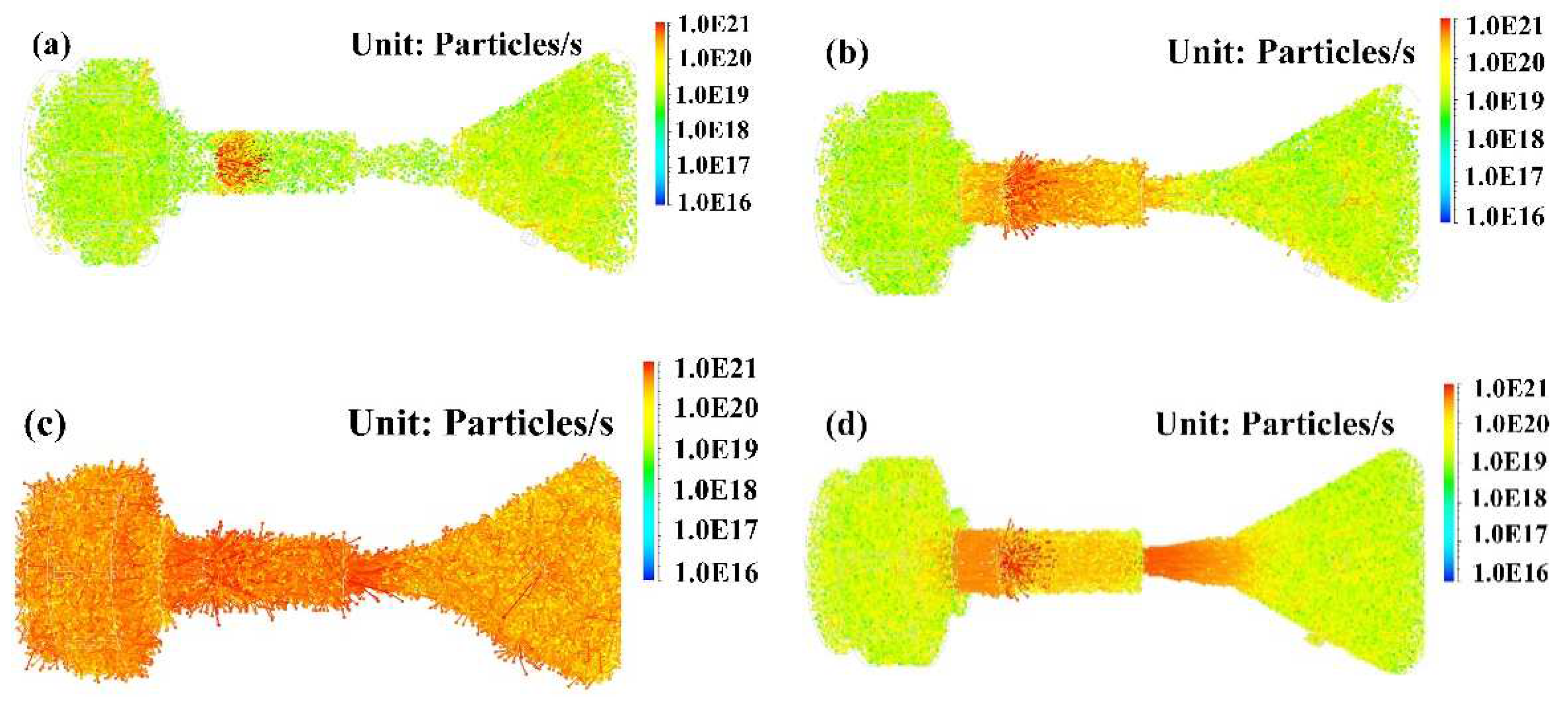
Figure 2 shows the flux distribution of gas particles (CO) at 100 ns, 1 ms, 20 ms, and 100 ms for a single pulse (100 ns). It can be seen that the gas particles were initially mainly located at the cathode. Subsequently, they diffused around the chamber and, with time, they were distributed throughout the chamber. Then, due to the effect of the getter, the gas particles were mainly located at the cathode and the connection of the diode pump port.
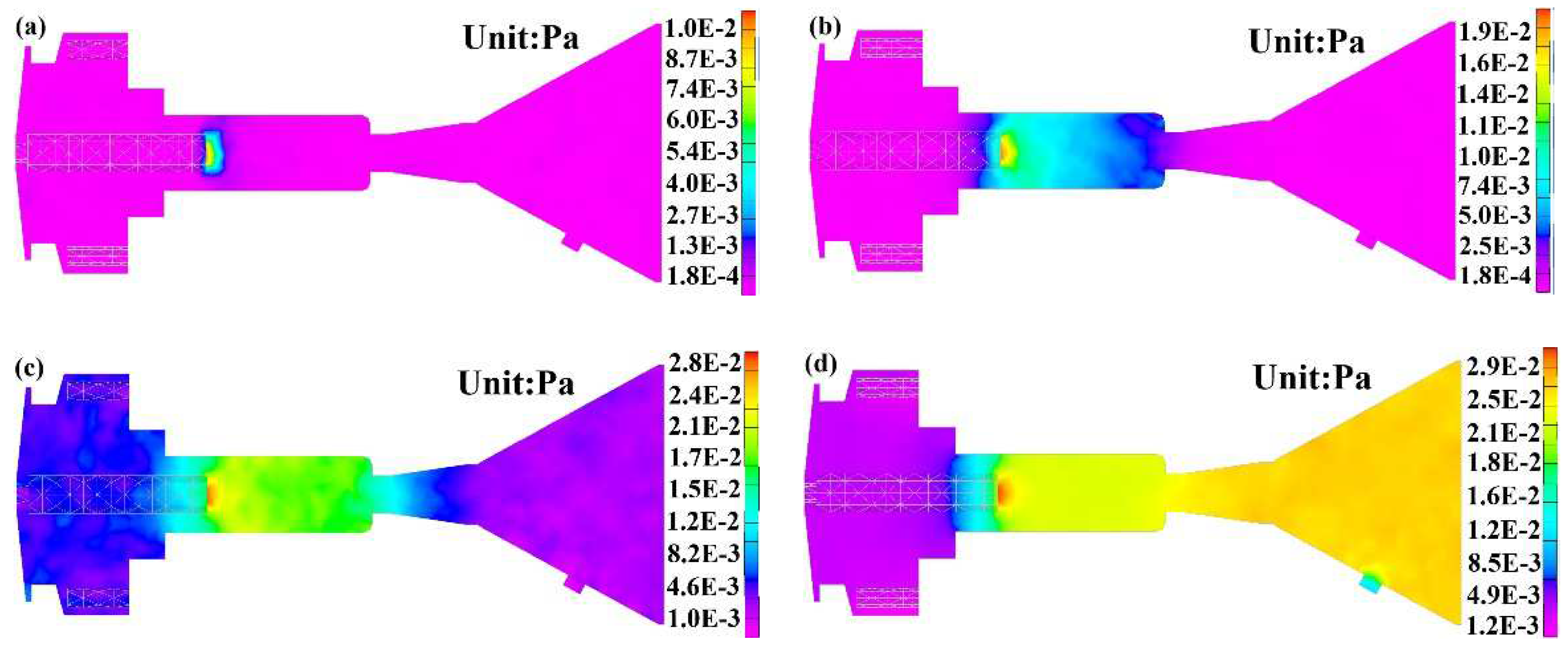
The simulated evolution of the single pulse desorption is presented in Figure 3. As shown in Figure 3a, after a discharge pulse (100 ns), the desorbed gas was mainly concentrated at the cathode, and the maximum pressure at the gas source was approximately 1 × 10⁻² Pa. Meanwhile, the other location in the TTO tube was at the background pressure, which was approximately 2 × 10⁻⁴ Pa. With the movement of the gas source, the pressure at the microwave source gradually increased at 1 ms in Figure 3b. Due to the effect of the getter, the gas particles were captured at the surface of the getter, as shown in Figure 3c, and the pressure at the pump port dropped to the order of 10−3 Pa at 20 ms. After 100 ms, the vacuum condition inside the chamber was effectively maintained within the duration of a single pulse, as shown in Figure 3d. This simulation result suggests that the vacuum-sealed TTO tube could operate at a repetition rate of 10 Hz under this vacuum environment.
To investigate the factors that affect the equilibrium pressure at the diode, the pressure variation with the gas flux and pumping speed was simulated. It can be seen in Figure 4a that the pressure at the diode changed with the variation in the gas flux from the cathode when other conditions remained unchanged. With the increase in the gas flow, the pressure increased initially and then remained almost unchanged after a period of time (the amount of gas released was almost the same as the amount of gas absorbed), reaching an equilibrium pressure, which was approximately proportional to the flow rate. The variation in the pressure under different pumping speeds is shown in Figure 4b. It was clear that with the increase in the pumping speed, the equilibrium pressure gradually decreased, but when the pumping speed increased to a certain value, in the limited simulation time, the pressure variation trend was consistent with the increase in the pumping speed.
Five pulses were simulated under the conditions of a discharge pulse (100 ns), where the gas particle to be monitored was set to CO, the pumping speed was 180 L/s, the gas flow rate was 1021 molecules/s.m2, and the initial pressure was 1.8 × 10⁻⁴ Pa. The pressure distribution of the three monitoring points set at the diode system, microwave source, and radiation system are shown in Figure 5. In this figure, 1, 2, 3, 4, and 5 are the five pulse pressure peaks, and the duration of a single pulse was 100 ms. After a discharge pulse, the pressure at the diode gradually increased from the base pressure and reached the maximum pressure of 4.0 × 10⁻² Pa at 50 ms. In the next 50 ms, the pressure gradually decreased due to the effect of the getter. After a burst of five pulses, an equilibrium pressure of 3.0 × 10⁻³ Pa was reached at the diode, and it took about 300 ms to reach nearly 10 percent of the maximum pressure. Meanwhile, the pressure at the microwave source and radiation system also increased from the background pressure and reached a maximum value of 4.0 × 10⁻² Pa at 50 ms and gradually decreased in the next 50 ms. After a burst of five pulses, the pressure of the microwave source dropped to nearly 2.0 × 10⁻² Pa and that of the radiation system dropped to nearly 1.0 × 10⁻² Pa. Compared with the microwave source and radiation system, the pumping system at the diode could significantly reduce the equilibrium pressure. It is evident from the simulation results that the equilibrium pressure at the diode was an order of magnitude smaller than the maximum pressure, and the duration of a single pulse was about 1/3 of the pressure recovery time.

3. Experiments

3.1. Experimental Setup

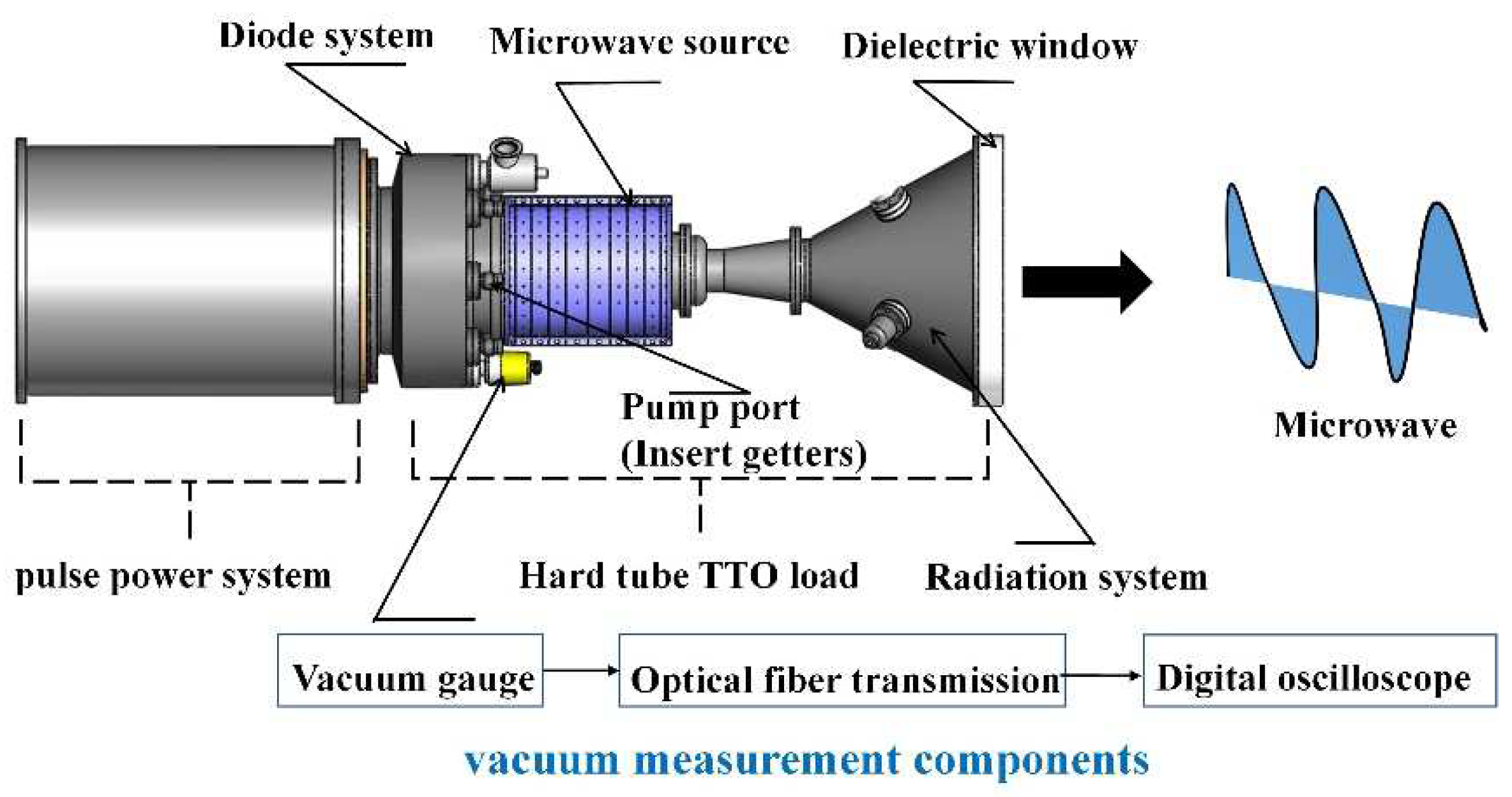
To verify the accuracy of the simulation results, a 10 Hz repetition rate experiment with five pulses was conducted on a hard-tube TTO based on a gigawatt-level pulse generator. The experimental setup is shown in Figure 6, where the structure of the hard-tube TTO consisted of a diode system, microwave source, suction unit (getter), measurement components, and radiation system that included a poly (ether-ether-ketone) (PEEK) dielectric window. In the system, the PEEK interface was sealed with fluorine rubber and the other interfaces were sealed by metal.
In the experiment, high voltages and currents were applied to the pulse generator, and the local electric field was enhanced, causing electrons to be released from the cathode and hit the anode to produce a relativistic electron beam, while the microwave source converted the high-power electrical pulse into an electromagnetic wave, which was eventually radiated in the specified direction by an antenna. The nature of the diode system [36] was such that its ceramic interface could withstand the high voltage provided at the pulse generator. In addition, the system was designed with magnetic insulation conditions. Most importantly, the device needed to maintain a high vacuum environment, which could generate the normal microwave output.
To accurately monitor the change in the internal pressure of the device during the pulse desorption, an online vacuum measurement method [37] was used in this experiment. A vacuum gauge was placed at the diode, and the measured signal was transmitted to the optical fiber through the transmission module and then to the digital oscilloscope. The capacitive voltage divider and B-dot [38] probe were located between the pulser and TTO to measure the voltage and current signals. The microwave power was obtained through the radiation system.
To verify that the graphite cathode was the main source of outgassing, the hard-tube TTO device was subjected to leak-detection test. The system leak rate was 1.0 × 10⁻¹² Pa·m3/s, which met the experimental requirements. To further reduce the operating pressure, the device was baked at 120 °C for 12 h before the experiment, and the NEG pump with a pumping speed of 180 L/s was activated to ensure that the device could be recovered quickly after a discharge pulse. After a series of treatments, the pressure in the device reached approximately 1 × 10⁻⁴ Pa, and the experiment was carried out.

3.2. Experimental Results

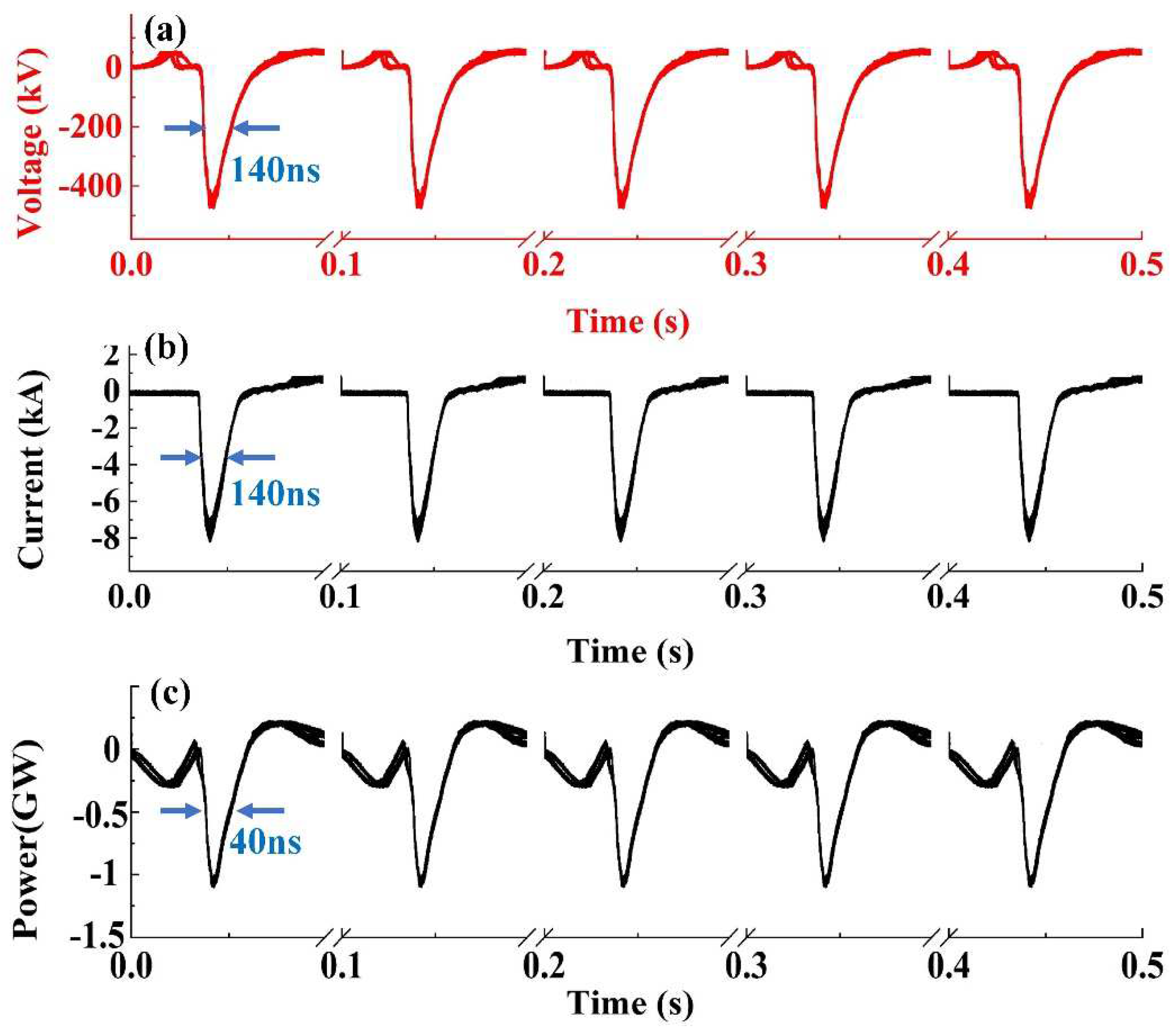
The typical voltage and current waveforms obtained experimentally for the five pulses at the diode are shown in Figure 7a,b. The average peak voltage and peak current of the output pulses were approximately 500 kV and 8 kA, respectively. A typical output microwave waveform obtained in the experiment is shown in Figure 7c. This waveform was obtained by using a LECROY oscilloscope in the adjacent mode after the attenuation and detection. It can be seen that the average output microwave power was 1 GW during the pulse duration of 40 ns. Further, no pulse-shorting limitation [39] (the width of output microwave pulse was normal) and no ceramic surface flashover (no discharge along the insulating surface) [40] were discovered during the 10 Hz repetition rate operation, which verified the success of the experiment.
The internal pressure of the device obtained by the online vacuum measurement method in the experiment is shown in Figure 8. Here, 1, 2, 3, 4, and 5 represent the peaks of the five pulses, respectively. It can be seen that the peak pressures of the first three pulses gradually increased, but they did not continue to rise in the last two pulses. This was because the graphite cathode material had a low outgassing rate. During repetitive operation, under certain pumping speed conditions, the pressure could not be increased infinitely. There was a limit value, which was determined by the volume of each deflation, the effective pumping speed of the suction unit, and the pulse interval.
A schematic of the online vacuum measurement is shown in Figure 8a. In the control circuit, the vacuum gauge was used to examine the pressure changes caused by the ionization of gas molecules under low pressure. The obtained data was passed through an amplifier to obtain the information on the change in pressure over time. Figure 8b shows the diode pressure obtained by the online vacuum-measurement method, and the background pressure in the device was obtained as 2.8 × 10⁻⁴ Pa. During the pulse desorption, the pressure rose rapidly from the background pressure to the maximum pressure (4.9 × 10⁻² Pa). Further, there was a certain drop due to the effect of the getter, and the duration of each pulse was nearly 100 ms. After the five discharge pulses, the device gradually reached the internal equilibrium pressure. The equilibrium pressure was 4.0 × 10⁻³ Pa, which was reduced to about 1/10 of the maximum value, and the pressure recovery time was approximately 300 ms. Furthermore, the experimental results were basically consistent with the simulation results.

4. Conclusions

In this study, the output of high-power microwaves was influenced by the vacuum environment within the chamber, and the main factor affecting the vacuum level was the pulsed outgassing process. To investigate this process, a dynamic pumping model was established for a repetitively operated, hard-tube TTO structure based on the DSMC method. The evolution of gas particles and pressure distribution during the pulse desorption was simulated. To verify the accuracy of the simulation results, a 10 Hz repetition rate experiment was carried out on a TTO based on a 5 GW pulse generator. The typical voltage and current waveforms were obtained by using a capacitive voltage divider and a B-dot probe, where the output voltage was 500 kV, and the output current was 8 kA. Moreover, the average output microwave power obtained by the radiation system during the pulse duration of 40 ns was 1 GW.
Since the pump system speed and the gas flux could affect the internal pressure of the device, the variation in the pressure as a function of gas flux and pumping speed was simulated. The results revealed that when only the pumping speed of the pump was changed, the equilibrium pressure in the chamber gradually decreased with the increase in the pumping speed. When the pumping speed was increased to a certain value, in the limited simulation time, the trend of pressure change was consistent with the increase in the pumping speed. When only the gas flux was changed, the internal equilibrium pressure of the device was approximately proportional to the gas flux.
In contrast to previous work, the model was established using the DSMC method based on the hard tube of a high-power microwave source with the devices of the vacuum system (including the diode, microwave, and antenna). Comparing the results of the simulation and experiment, it was observed that the equilibrium pressure was an order of magnitude smaller than the maximum pressure, and the duration of a single pulse was nearly 1/3 of the pressure recovery time. Furthermore, the simulation results were in excellent agreement with the experimental results, which verified the accuracy and reliability of the proposed model and that there was a GW-level microwave output achieved under a 10 Hz repetition rate. Overall, in the future we can observe the pressure changes insides the device by modifying the parameters in the simulation to adjust the position of the gas source and the pump port surfaces. The proposed simulation model can be used to optimize the hard-tube structures, improve the output power level of the device under repetitive operation, and provide technical support for subsequent vacuum-maintenance experiments in a hard-tube.

Author Contributions

Conceptualization, T.X.; methodology, S.T.; software, S.T. and R.W.; validation, J.L. and Q.Z.; formal analysis, X.C.; investigation, X.C.; resources, T.X. and Z.L.; writing—original draft preparation, S.T., T.X. and R.W.; writing—review and editing, S.T. and Z.L.; visualization, X.C.; supervision, J.L.; project administration, T.X.; funding acquisition, T.X. All authors have read and agreed to the published version of the manuscript.

Funding

This research was funded by the National Natural Science Foundation of China (Grant No. 62071477).

Institutional Review Board Statement

Not applicable.

Informed Consent Statement

Not applicable.

Data Availability Statement

Data is contained within the article.

Conflicts of Interest

The authors declare no conflict of interest.

References

  1. He, J. Research on a New Transit Time Oscillator; National University of Defense Technology: Changsha, China, 2004. [Google Scholar]
  2. Barker, R.J.; Schamiloglu, E. High-Power Microwave Sources and Technologies; Wiley-IEEE Press: Hoboken, NJ, USA, 2001. [Google Scholar]
  3. Ling, J.; He, J.; Zhang, J.; Cao, Y.; Bai, X. Simulation of Traveling Wave Extraction Coaxial Transit Time Oscillator. J. Natl. Univ. Def. Technol. 2013, 35, 120–125. [Google Scholar]
  4. Adhikary, B.; Shyam, A.; Shukla, R.; Sharma, S.K. Fast Marx Generator for Directly Driving a Virtual Cathode Oscillator. J. Korean Phys. Soc. 2011, 59, 3476–3480. [Google Scholar] [CrossRef]
  5. Schamiloglu, E. High Power Microwave Sources and Applications. IEEE MTT-S 2004, 2, 1001–1004. [Google Scholar]
  6. Sedek, E.; Slomski, R. Overview of Microwave Direct Energy Weapons. In Proceedings of the 2015 Signal Processing Symposium (SPSympo), Debe, Poland, 10–12 June 2015; pp. 1–3. [Google Scholar]
  7. Sannibale, F.; Filippetto, D.; Papadopoulos, C.F.; Staples, J.; Wells, R.; Bailey, B.; Baptiste, K.; Corlett, J.; Cork, C.; De Santis, S.; et al. Advanced photoinjector experiment photogun commissioning results. Phys. Rev. Spec. Top.-Accel. Beams 2012, 15, 103501. [Google Scholar] [CrossRef] [Green Version]
  8. Walter, J.W.; Lynn, C.F.; Dickens, J.C.; Kristiansen, M. Operation of a sealed-tube-vircator high-power-microwave source. IEEE Trans. Plasma Sci. 2012, 40, 1618–1621. [Google Scholar] [CrossRef]
  9. Jeon, W.; Lim, J.E.; Moon, M.W.; Jung, K.B.; Park, W.B.; Shin, H.M.; Seo, Y.; Choi, E.H. Output characteristics of the high-power microwave generated from a coaxial vircator with a bar reflector in a drift region. IEEE Trans. Plasma Sci. 2006, 34, 937–944. [Google Scholar] [CrossRef]
  10. Knoll, M. Materials and Processes of Electron Devices; Springer: Berlin, Germany, 1959. [Google Scholar]
  11. Rosebury, F. MIT Tube Laboratory Manual; MIT Press: Cambridge, MA, USA, 1951. [Google Scholar]
  12. Parson, J.M.; Lynn, C.F.; Scott, M.C.; Calico, S.E.; Dickens, J.C.; Neuber, A.A.; Mankowski, J.J. A frequency stable vacuum-sealed tube high-power microwave vircator operated at 500 Hz. IEEE Electron Device Lett. 2015, 36, 508–510. [Google Scholar] [CrossRef]
  13. Xun, T.; Fan, Y.W.; Yang, H.W.; Zhang, Z.C.; Chen, D.Q.; Zhang, J.D. A vacuum-sealed, gigawatt-class, repetitively pulsed high-power microwave source. J. Appl. Phys. 2017, 121, 234502. [Google Scholar] [CrossRef]
  14. Kelly, P.M.; Parson, J.M.; Lynn, C.; Taylor, M.; Dickens, J.C.; Neuber, A.; Mankowski, J.; Calico, S.; Scott, M. Performance of St707 getter material in a rep-rated high power microwave sealed-tube vircator under UHV conditions. In Proceedings of the 2014 IEEE International Power Modulator and High Voltage Conference (IPMHVC), Santa Fe, NM, USA, 1–5 June 2014; pp. 213–216. [Google Scholar]
  15. Mumtaz, S.; Lim, J.S.; Ghimire, B. Enhancing the power of high-power microwaves by using zone plate and investigations for the position of virtual cathode inside the drift tube. J. Plasma Phys. 2018, 25, 103113. [Google Scholar] [CrossRef]
  16. Xun, T.; Zhao, Y.; Yang, H.; Hu, T.; Zhang, Z.; Cheng, X.B.; Zhang, J.; Zhang, J.; Zhong, H.H. Developments of pulsed electron beam sources for high-power microwave applications. IEEE Access 2020, 8, 101351–101358. [Google Scholar] [CrossRef]
  17. Xun, T.; Yang, H.; Zhang, J.; Zhang, Z. Effects of vacuum pressures on the performance of a velvet cathode under repetitive high-current pulse discharges. Vacuum 2010, 85, 322–326. [Google Scholar] [CrossRef]
  18. Zhao, X.; Xun, T.; Liu, L.; Cai, D. Maintenance of high vacuum level in a compact and lightweight sealed hard-tube magnetically insulated line oscillator system. Vacuum 2015, 111, 55–59. [Google Scholar] [CrossRef]
  19. Li, A.K.; Fan, Y.W.; Qian, B.L.; Li, S.; Yang, H.W. Improvement of vacuum maintenance capability and output pulse limit in a hard-tube MILO with a carbon fiber array cathode. Vacuum 2020, 181, 109723. [Google Scholar] [CrossRef]
  20. Xun, T.; Zhang, J.; Yang, H.; Zhang, Z. A distributed pumping model for a repetitive operated magnetically insulated transmission line oscillator. J. Appl. Phys. 2013, 113, 164505. [Google Scholar]
  21. Li, L.; Men, T.; Liu, L. Dynamics of virtual cathode oscillation analyzed by impedance changes in high-power diodes. Int. J. Appl. Phys. 2007, 102, 123309. [Google Scholar] [CrossRef]
  22. Cuneo, M.E.; Menge, P.R.; Hanson, D.L.; Fowler, W.E.; Bernard, M.A.; Ziska, G.R.; Filuk, A.B.; Pointon, T.D.; Vesey, R.A.; Welch, D.R.; et al. Results of vacuum cleaning techniques on the performance of LiF field-threshold ion sources on extraction applied-B ion diodes at 1-10 TW. IEEE Trans. Plasma Sci. 1997, 25, 229–251. [Google Scholar] [CrossRef]
  23. Cuneo, M.E. The effect of electrode contamination, cleaning and conditioning on high-energy pulsed-power device performance. IEEE Trans. Dielectr. Electr. Insul. 1999, 6, 469–485. [Google Scholar] [CrossRef]
  24. Shen, C. Direct Simulation Monte-Carlo (DSMC) Method. In Rarefied Gas Dynamics: Fundamentals, Simulations and Micro Flows; Springer: Berlin/Heidelberg, Germany, 2005; pp. 275–315. [Google Scholar]
  25. Borgnakke, C.; Larsen, P.S. Statistical collision model for Monte Carlo simulation of polyatomic gas mixture. J. Comput. Phys. 1975, 18, 405–420. [Google Scholar] [CrossRef]
  26. Alexander, F.J.; Garcia, A.L. The direct simulation Monte Carlo method. Comput. Phys. 1997, 11, 588–593. [Google Scholar] [CrossRef]
  27. Bird, G.A. Molecular Gas Dynamics and the Direct Simulation of Gas Flows; Clarendon Press: Oxford, UK, 1994. [Google Scholar]
  28. Sharipov, F. Rarefied Gas Dynamics: Fundamentals for Research and Practice; John Wiley & Sons: Hoboken, NJ, USA, 2015. [Google Scholar]
  29. Park, W.; Tokioka, H.; Tanaka, M.; Choi, J. DLC coating on a micro-trench by bipolar PBII&D and analysis of plasma behaviour. J. Phys. D Appl. Phys. 2014, 47, 335306. [Google Scholar]
  30. Maccallini, E.; Siviero, F.; Bonucci, A.; Conte, A.; Srivastava, P.; Paolo, M. Non evaporable getter (NEG) technology: A powerful tool for UHV-XHV systems. In AIP Conference Proceedings; American Institute of Physics: Melville, NY, USA, 2012; Volume 1451, pp. 24–27. [Google Scholar]
  31. Rocha, E.; Kelly, P.M.; Parson, J.M.; Lynn, C.F.; Dickens, J.C.; Neuber, A.A.; Mankowski, J.J.; Queller, T.; Gleizer, J.; Krasik, Y.E.; et al. Evaluating the performance of a carbon-epoxy capillary cathode and carbon fiber cathode in a sealed-tube vircator under UHV conditions. IEEE Trans. Plasma Sci. 2015, 43, 2670–2675. [Google Scholar] [CrossRef]
  32. Ozawa, T.; Suzuki, T.; Fujita, K. Investigation of condensation and evaporation effect on CO2 hypersonic rarefied aerodynamic measurements. In AIP Conference Proceedings; AIP Publishing LLC: Melville, NY, USA, 2019; Volume 2132, p. 050004. [Google Scholar]
  33. Balat-Pichelin, M.; Iacono, J.; Boubert, P. Recombination coefficient of atomic oxygen on ceramic materials in a CO2 plasma flow for the simulation of a Martian entry. Ceram. Int. 2016, 42, 2761–2769. [Google Scholar] [CrossRef]
  34. Vara, J. Anode Material Testing in a Vacuum Diode. Master’s Thesis, Texas Tech University, Lubbock, Texas, USA, May 2011. [Google Scholar]
  35. Yoshimura, N. Vacuum Technology: Practice for Scientific Instruments; Springer Science & Business Media: Berlin/Heidelberg, Germany, 2007. [Google Scholar]
  36. Qiu, A.; Li, Y.; Wang, Z.; Shen, Z.; Zhang, Y.; Zeng, Z.; Zhang, J.; Gai, T. A relativistic electron beam accelerator—Flash II. High Power Laser Part. Beams 1991, 3, 340–348. [Google Scholar]
  37. Wang, R.; Lv, Y.; Luo, L.; Zhu, W.; Xun, T. On-line vacuum measurement of a high-power microwave source. High Power Laser Part. Beams 2018, 30, 43–47. [Google Scholar]
  38. Tan, R.R.; Ran, H.; Cheng, G. A B-Dot-based method for short pulse current measurement at kA level. J. Terahertz Sci. Electron. Inf. 2015, 13, 990–994. [Google Scholar]
  39. Miller, R.B. Mechanism of explosive electron emission for dielectric fiber (velvet) cathodes. J. Appl. Phys. 1998, 84, 3880–3889. [Google Scholar] [CrossRef]
  40. Xun, T.; Yang, H.W.; Zhang, J.D. A high-vacuum high-electric-field pulsed power interface based on a ceramic insulator. IEEE Trans. Plasma Sci. 2015, 43, 4130–4135. [Google Scholar] [CrossRef]
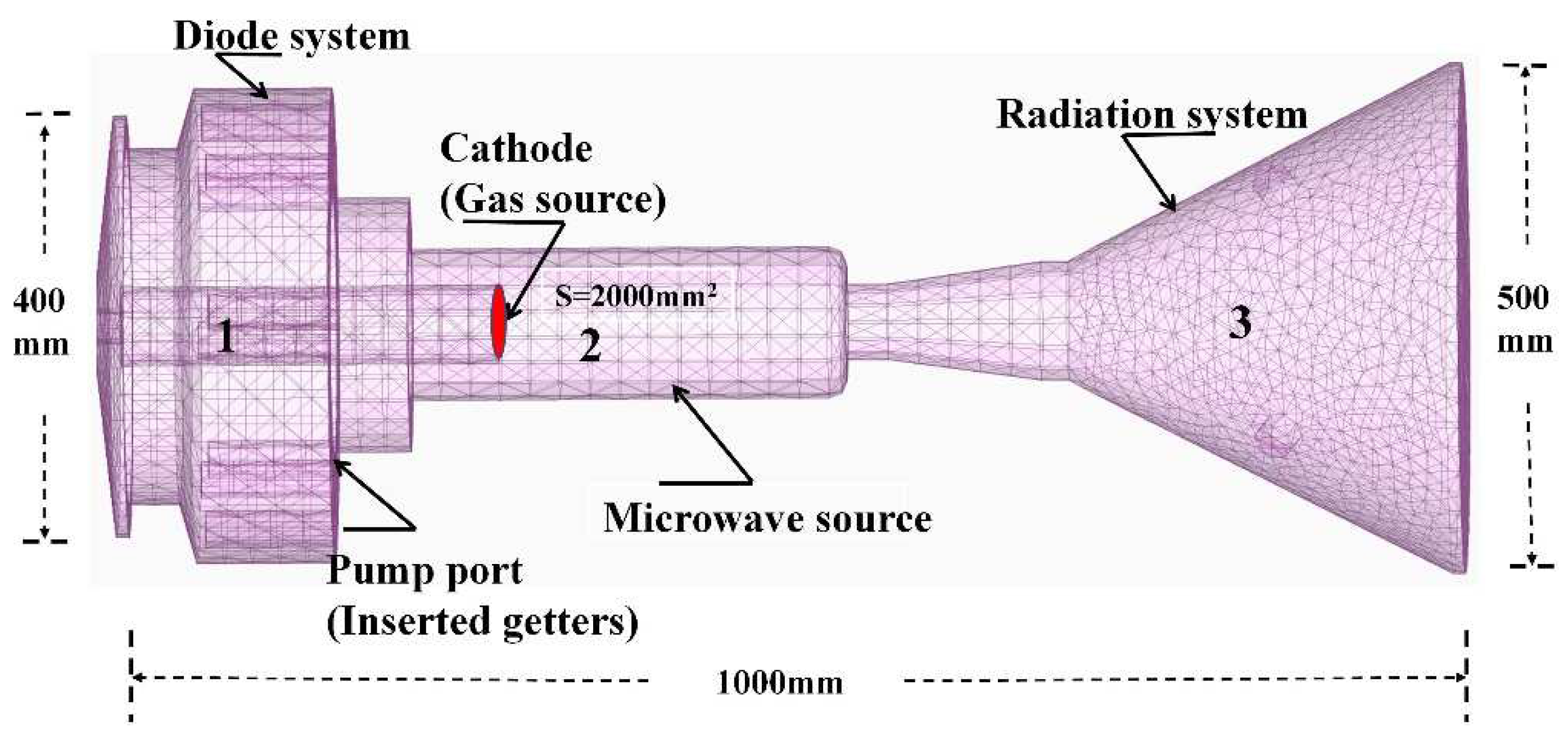
Figure 1. Schematic of dynamic pumping model.
Electronics 11 03444 g001
Figure 2. Flux distribution of the gas particles at: (a) 100 ns, (b) 1 ms, (c) 20 ms, and (d) 100 ms.
Electronics 11 03444 g002
Figure 3. Pressure distribution of the gas particles at: (a) 100 ns, (b) 1 ms, (c) 20 ms, and (d) 100 ms.
Electronics 11 03444 g003
Figure 4. Variation in the pressure as a function of (a) gas flux and (b) pumping speed.
Electronics 11 03444 g004
Figure 5. Pressure distribution at the three monitoring points.
Electronics 11 03444 g005
Figure 6. Schematic illustration of the experimental setup.
Electronics 11 03444 g006
Figure 7. (a) Typical diode voltage waveforms, (b) current waveforms, and (c) microwave waveforms.
Electronics 11 03444 g007
Figure 8. (a) Schematic of the online vacuum measurement. (b) Diode pressure obtained by the online vacuum-measurement method.
Electronics 11 03444 g008
Publisher’s Note: MDPI stays neutral with regard to jurisdictional claims in published maps and institutional affiliations.