Case Report

Analysis of Short-Circuit and Dielectric Recovery Characteristics of Molded Case Circuit Breaker according to External Environment

1
Reliability Assessment Center, Hyundai Electric & Energy System Co., Ltd., 17-10 Mabuk-ro, 240 bean-gil, Giheung-gu, Yongin-si 16891, Gyeonggi-do, Korea
2
Launcher Technology Development Division, Korea Aerospace Research Institute, Daejeon 34133, Korea
3
Department of Electrical & Control Engineering, Cheongju University, 298 Daeseong-ro, Cheongwon-gu, Cheongju-si 360764, Chungcheongbuk-do, Korea
4
School of Social Safety System Engineering, Research Center for Safety and Health, Hankyoung National University, 327 Chungang-ro, Anseong-si 1704, Gyeonggi-do, Korea
*
Authors to whom correspondence should be addressed.
Electronics 2022, 11(21), 3575; https://doi.org/10.3390/electronics11213575
Submission received: 6 October 2022 / Revised: 20 October 2022 / Accepted: 30 October 2022 / Published: 1 November 2022

Abstract

:
A molded case circuit breaker (MCCB) is one of the most important factors for safety to protect a load from overcurrent in a power distribution system. MCCB, which is mainly installed in switchboards and distribution boxes, may be affected by external temperatures and magnetic fields, but the above factors are still excluded from product standards and performance evaluation. This paper is the result of experimenting and studying the negative effects of these external temperatures and external magnetic fields on MCCB with short-circuit characteristic and dielectric recovery strength. As a result of temperature, it can be found that both short-circuit characteristic and dielectric recovery strength change linearly in accordance with the external temperature. The ratio of the values of 35 °C to 25 °C and 45 °C to 25 °C show the following results. t10, t21, and t32 are 1.58, 1.53, and 1.79, respectively, in short-circuit characteristics and ti, tm, and tl are 1.59, 1.69, and 1.53, respectively, in dielectric recovery strength. Depending on the external magnetic field, the short-circuit characteristics decreased by 8.56% only in the t21 period. The dielectric recovery strength decreases by 4.92% in the initial section (ti) and 14.45% in the later section (tl), respectively. It has been confirmed that the external magnetic field interferes with the emission of hot gas.

1. Introduction

A molded case circuit breaker (MCCB) is the closest circuit breaker to the consumer among medium- and low-voltage circuit breakers installed to protect the load from overcurrent in the power distribution system. Therefore, it is essential to secure the reliability of the wiring breaker in order to protect the load. The environment in which the MCCB is installed is mainly located in the electrical chamber of the building and in the distribution box of each floor. In such an environment, the wiring breaker is affected by ambient conditions such as temperature and magnetic field by devices installed together.
After the development process, the circuit breaker is tested according to the product standard to verify the function and performance before mass production. The product standards used for breakers with AC 1000 V or less (DC 1500 V or less) are as follows. In IEC 60947-2 “Low-voltage switchgear and controlgear—Part 2: Circuit-breakers”, the trip characteristics, short-circuit characteristics, withstand voltage, and dielectric strength and mechanical strength of the circuit breaker are tested, and a temperature rise test between each test is performed [1]. However, the temperature rise test conducted in the test standard focuses only on the temperature rise (∆T) and does not verify performance such as trip characteristics and short-circuit characteristics depending on the temperature of the environment where the breaker is installed. In addition, circuit breaker manufacturers generally manage the performance for the trip according to ambient temperature, but they are less interested in short-circuit characteristics.
As mentioned above, in an environment where a circuit breaker is installed, not only heat is generated, but magnetic fields are also generated by devices and systems. IEC 60947-1 “Low-voltage switchgear and controlgear—Part 1: General rules”, a product standard for low-pressure switchgear, includes verifying the performance of magnetically sensitive devices with the magnetic field test from an EMC perspective [2]. However, based on this, Annex F of IEC 60947-2, an EMC requirement applied to breakers with overcurrent protection, does not include the corresponding magnetic field test. Although it is not a magnetic field-sensitive device as much as a protection relay, communication, and measurement device (etc.) that communicates with a parent system or directs measurement and operation, the operation of a circuit breaker may be affected by a magnetic field. Therefore, it is necessary to analyze and consider the impact of external conditions on the breaker.
Even if it is not required by the product standard, the dielectric recovery characteristics between electrodes by residual hot gas existing in the arc extinguishment chamber after current zero are also important for performance among the characteristics of the circuit breaker. When separating electrodes during the blocking process, the arcs generated between the electrodes form high-temperature hot gas inside the arc-extinguishment chamber. This causes a decrease in the dielectric strength between the fixed electrode and the moving electrode to remain inside the arc extinction chamber even after the arc is extinguished after the current zero. dielectric. This means that although the circuit breaker operates normally, the overcurrent blocking fails, resulting in load burnout [3]. Therefore, the dielectric recovery characteristics of the circuit breaker according to the installation environment must be considered to increase the reliability of the circuit breaker as well as the short-circuit characteristics.
Currently, research on the impact of the surrounding environment on breakers and components is being conducted. Szulborski, M et al. analyzed the temperature distribution of the entire current path (from the trip coil to the fixed electrode, moving electrode, arc runner, arc extinguishment unit, and wire terminal) of the miniature circuit breaker (MCB) through a finite element method (FEA) simulation [4]. They also analyzed the magnetic field that generates a force moving toward the splitter plate inside the arc extinguishment chamber [5]. Yang, W et al. analyzed the effect of pressure, relative humidity, and temperature difference on MCB according to altitude through simulation [6]. In addition, various studies on LV or MV breakers are being conducted, and in particular, studies related to the DC system are increasing [7,8,9,10,11,12,13].
The composition of this paper is as follows: 2. Consideration of external environmental conditions, 3. experiment studies, and 4. conclusions. Section 2 deals with the consideration of external environmental conditions. Section 3 shows the results of measuring the short-circuit characteristics and the dielectric recovery voltage under external temperature and magnetic field conditions. Finally, Section 4 analyzes the experimental results and provides conclusions.
Previous studies have conducted assessments on the effect of the shape and material of the internal structure of the MCCB on the insulation recovery characteristics. In this study, the short circuit characteristics and insulation recovery characteristics under the external environmental conditions that the MCCB may be subjected to are analyzed. This has value as a non-verified part of the current product standard. In addition, the research direction for performance improvement of each characteristic is suggested.

2. Consideration of External Environmental Conditions

2.1. Temperature

The previous paper confirmed the effect of the material of the splitter plate inside the arc extinguishment chamber on the dielectric recovery characteristics of the breaker [14]. In this test result, it was analyzed how the thermal conductivity of the material affects the dielectric recovery voltage through one-way ANOVA (Analysis of Variance) analysis [15]. Table 1 shows the results of the dielectric recovery voltage when the splitter plate is made of steel, aluminum, and copper and is located in the arc extinguishment chamber. The dielectric recovery voltage was measured three times for each period to obtain the average value.
Figure 1 shows the main effect plot according to the material. In the initial period and the medium period, dielectric recovery voltage increases in proportion according to thermal conductivity. In particular, copper has a higher dielectric strength than the average value of the data. However, in the latter period, the dielectric recovery voltage is not proportional to the thermal conductivity, and aluminum appears to be the highest. In general, the dielectric recovery voltage is mainly affected by the cooling of hot gas in the initial stage and the emission in the latter stage. Therefore, thermal conductivity is the main factor in increasing dielectric recovery in the initial period, which is sensitive to temperature.
If the temperature around the circuit breaker changes, it affects the cooling and emission of hot gas inside the arc extinguishment chamber, so analysis is needed.

2.2. Magnetic Field

The short-circuit characteristic of the circuit breaker is affected by the Lorentz force generated by the shape from the terminal to the fixed electrode. Therefore, the force of opening the moving electrode changes according to the magnitude of the inflow overcurrent. In addition, depending on the magnetic field applied to the arc formed after the electrode separation, the force on the movement of the arc changes. Figure 2 shows the effect of this magnetic field on the breaker. As a current flow from a fixed electrode to a moving electrode, the direction of the force applied to an arc varies depending on the direction of the external magnetic field. This force disturbs or helps the arc move toward the splitter plate. Therefore, it is necessary to analyze the movement of the arc according to the external magnetic field [16].

3. Experiment Studies

The circuit used in the experiment is illustrated in Figure 3, which is generally used to measure the dielectric recovery voltage and inflow of over-current [17]. The capacitor bank CS charged by the rectifier generates overcurrent at the desired frequency with inductor L. An overcurrent generated by the operation of Thyr flows into the circuit breaker, and capacitor C0 connected in parallel to the circuit breaker is installed to model a recovery voltage of the system and arbitrarily perform re-ignition. In addition, an experiment is constructed by selecting the ambient temperature and the external magnetic field as external conditions in the circuit breaker. These experimental setups appear in Section 3.1 and Section 3.2, respectively.
In order to analyze the short-circuit characteristics and the dielectric recovery voltage, important measuring points in the waveform are shown in Figure 4. Figure 4a shows each point for the operation of the circuit breaker when an over-current inflows. t0 is the time that the overcurrent flows into the breaker, and t1 is the time when the electrodes begin to separate. t2 is the time when the arc formed after electrode separation reaches the splitter plate, and t3 is the timing of the current reaching zero after the arc is extinguished on the splitter plate. Therefore, t10 represents the time until the moving electrode is separated from the fixed electrode after the inflow of overcurrent, and t21 represents the time the arc moves to the splitter plate after the contact is disconnected. t31 represents the time at which the arc reaching the splitter plate is extinguished. Figure 4b shows each point of the dielectric recovery characteristics of the circuit breaker after the current reaches zero. When a recovery voltage exceeding the dielectric strength is applied between the fixed electrode and the moving electrode after the current reaches zero, the arc is re-formed and the voltage is discharged. The voltage at this time is VDRV, and the time taken from the current zero to the re-ignition is tDRV.

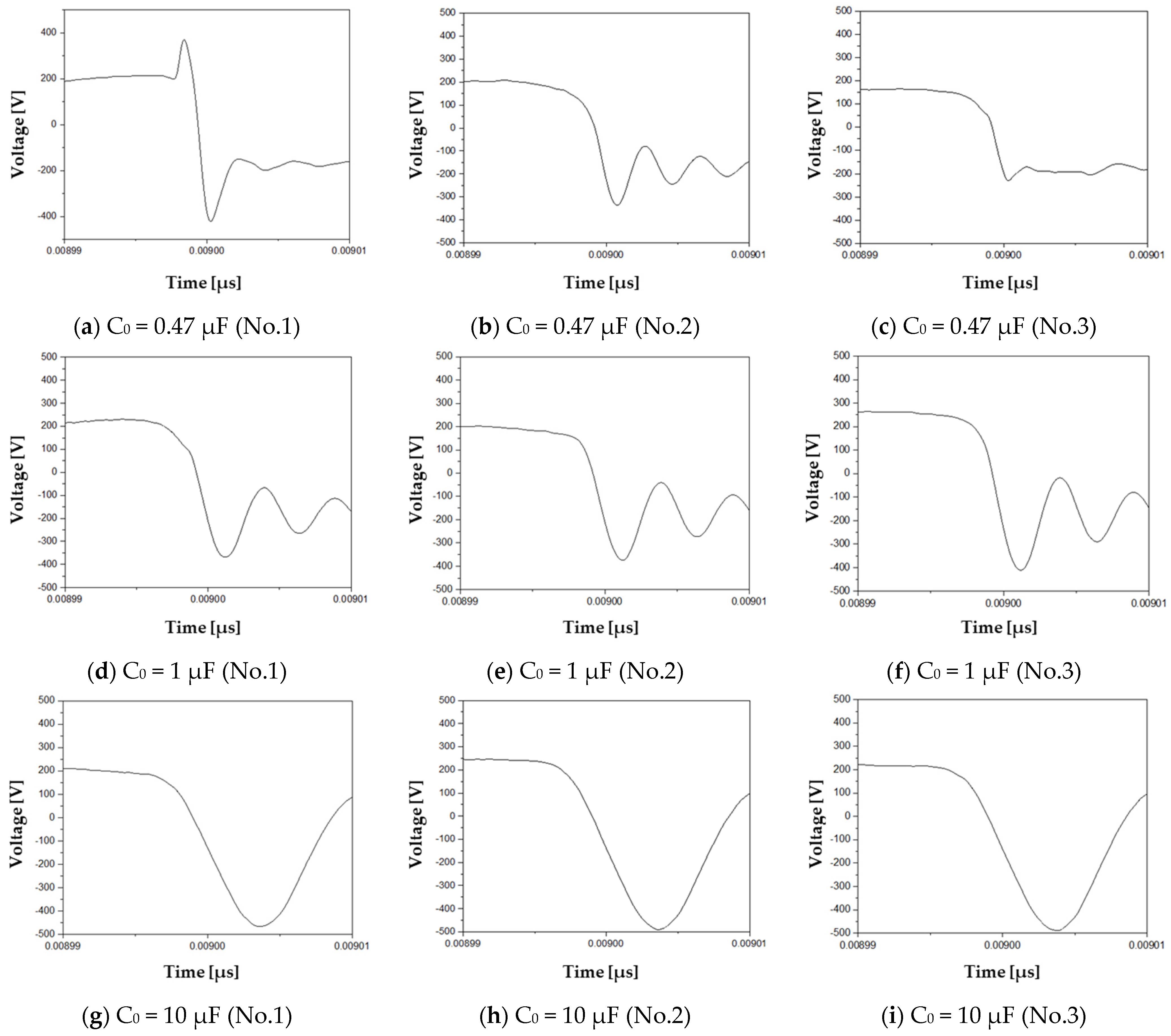
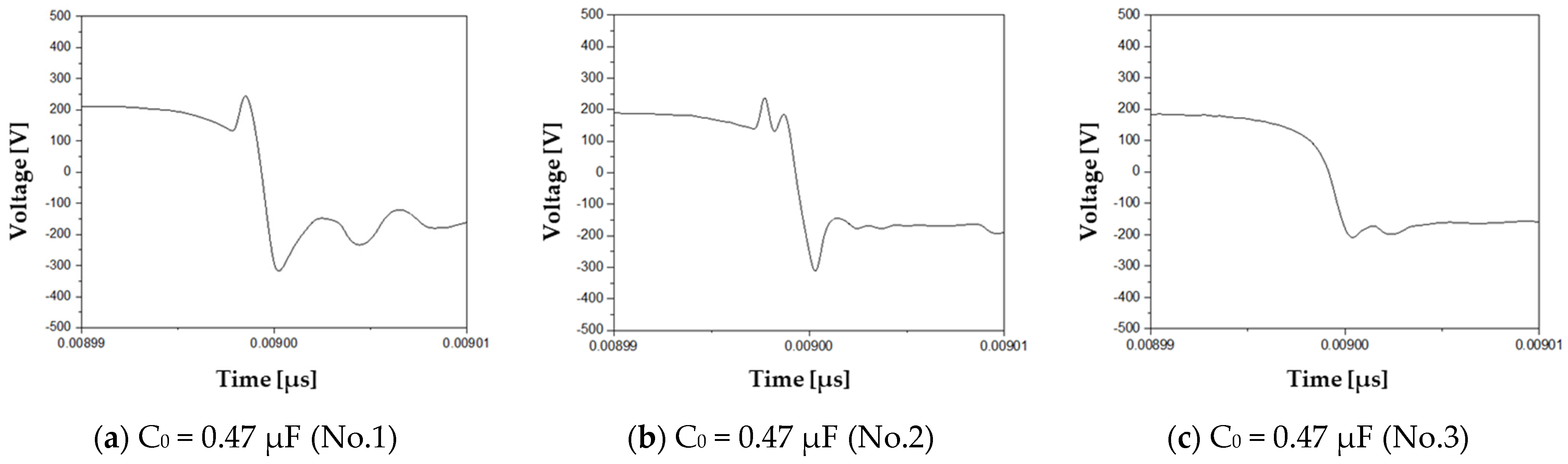
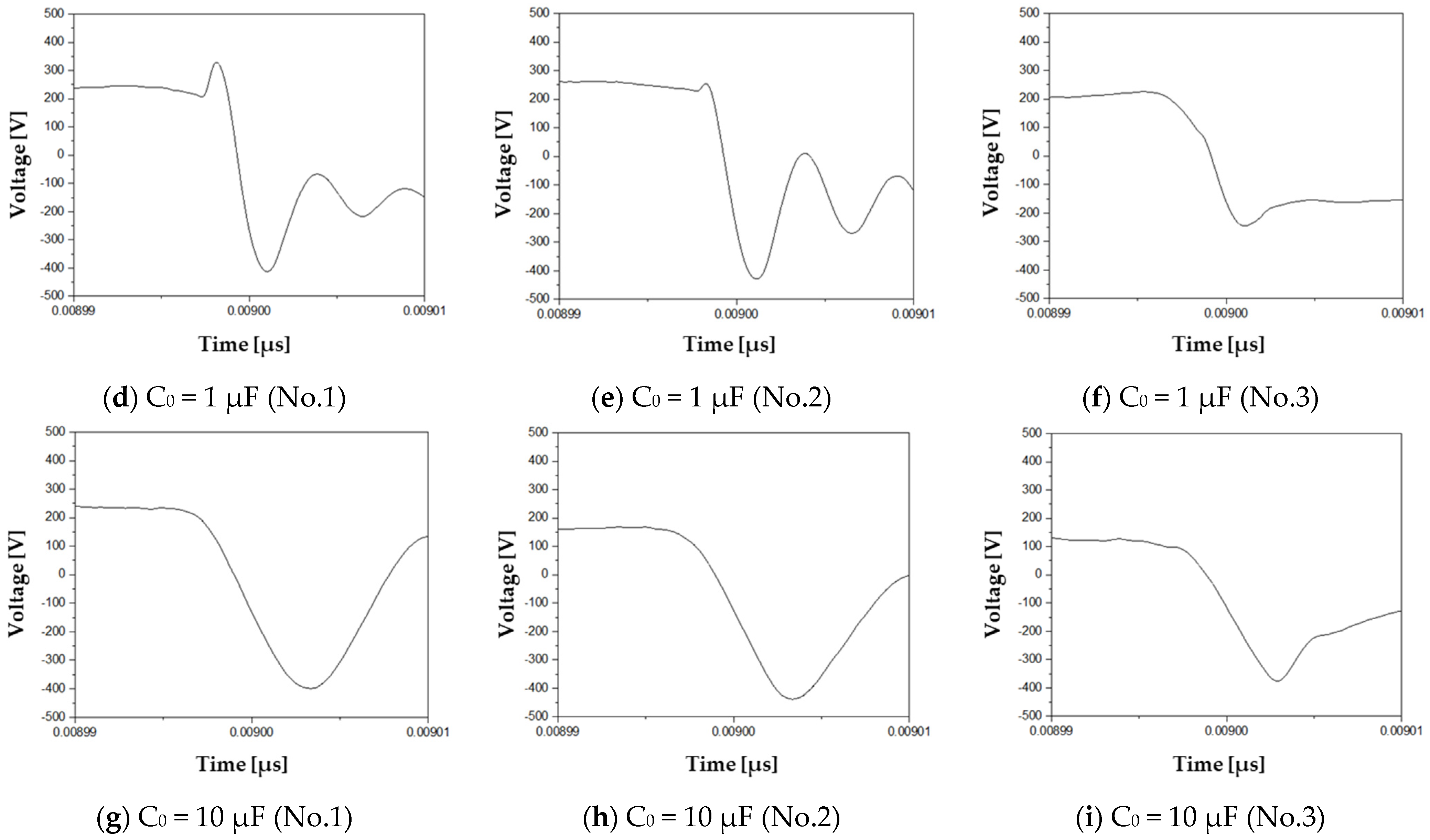
3.1. Temperature Test Results

In order to measure the short-circuit characteristics and the dielectric recovery voltage according to the ambient temperature, a simple chamber capable of maintaining a predetermined temperature is constructed (Figure 5). The experiment is conducted after maintaining the predetermined temperature for 1 h by a heater connected to the thermostat. Figure 6, Figure 7 and Figure 8 show short-circuit characteristics at 25 °C, 35 °C, and 45 °C, respectively. Table 2 shows the numerical values of these results.
The results are as follows. The values of t10 when the external temperatures are 25 °C, 35 °C, and 45 °C are 2.77 ms, 2.14 ms, and 1.78 ms, respectively. Compared to the value at 25 °C, the values of 35 °C and 45 °C are reduced by −22.5% and −35.6%, respectively. The electrodynamic repulsion force that determines the value of t10 consists of the Holm force and the Lorentz force [18]. Before the fixed electrode and the moving electrode are opened, the current flows intensively in a very small area. The electromagnetic repulsive force generated by the magnetic flux density between these electrodes is called the Holm force. Before the overcurrent enters the fixed electrode, it flows in opposite directions. This repulsive force is called the Lorentz force. The Holm force and the Lorenz force are expressed by the following formula.
F H o l m = μ 0 I 2 8 π ln ( 8 π H A μ 0 I 2 )
F L o r e n t z = 2 × 10 7 I 2 × l r
Here, I is the current, H is the hardness of the material, A is the area of the electrode, l is the length of the electrode arm, and r is the distance between the electrodes. As seen from the formula, Lorentz force has no temperature variable and is not affected by temperature. In the formula of the Holm force, the hardness H of the material is affected by the temperature. The hardness H of the material in this formula is the Brinell hardness (BH). Figure 9 shows the temperature-dependent ratio of BH based on a value of 25 °C [19].
Looking at the temperature range of 25 °C to 45 °C, the BH value increases, resulting in the Holm force increasing and t10 shortening.
Values of t21 when the external temperatures are 25 °C, 35 °C, and 45 °C are 4.24 ms, 4.91 ms, and 5.27 ms, respectively. Compared to the value at 25 °C, the values of 35 °C and 45 °C increased by +15.9% and +24.3%, respectively. t21 is the period where the arc current generated between the fixed electrode and the movable electrode moves in the direction of the splitter plate. At this time, the force acting on the arc current is largely due to the centrifugal force caused by the movable electrode and the pressure difference of the heated gas generated by the arc discharge. Assuming that the centrifugal force is constant, the pressure difference is as follows.
Δ P = n R V Δ T
The pressure difference that generates the force is determined by the temperature difference, which shows that the force decreases when the external temperature rises. In addition, the high external temperature has a limitation in extinguishing the arc current in the air.
The values of t32 when the external temperatures are 25 °C, 35 °C, and 45 °C are 1.45 ms, 1.54 ms, and 1.60 ms, respectively. Compared to the value at 25 °C, the values of 35 °C and 45 °C are increased by +5.7% and +10.2%, respectively. It is predictable that the lower the temperature of the splitter plate, the more advantageous it is to extinguish the arc current. The t10, t21, and t32 values at 35 °C and 45 °C were compared based on the values of t10, t21, and t32 at 25 °C, respectively. The ratios of these values at 35 °C and 45 °C are 1.58, 1.53, and 1.79 at t10, t21, and t32, respectively. It can be seen that it changes at a similar rate in all periods, and in the case of t32, it is slightly more affected. That is, it can be seen that the temperature affects the metal more than the air.
Figure 10, Figure 11 and Figure 12 show the dielectric recovery voltage at 25 °C, 35 °C, and 45 °C, respectively.
Table 3 shows the DRV at 25 °C, 35 °C, and 45 °C It shows the C0 values (0.47, 1, and 10 μF) and their corresponding average voltage and average time, respectively. Using these voltages and times, Figure 13 illustrates the DRV V-t curve according to the temperature.
This paper observes the DRV characteristics by dividing time into the initial time (ti), medium time (tm), and late time (tl). In general, the initial time is affected by the cooling performance of the splitter plate, and the latter time is affected by the emission of hot gas generated by arc extinguishment [20]. The results are as follows. The average time corresponding to each of the C0 values (0.47 μF, 1 μF, 10 μF) is 0.95 μs, 1.86 μs, and 4.45 μs, respectively. At ti, DRVs of 25 °C, 35 °C, and 45 °C are 279 V, 242 V, and 220 V, respectively. At tm, DRVs of 25 °C, 35 °C, and 45 °C are 381 V, 345 V, and 320 V, respectively. In this tl, DRVs of 25 °C, 35 °C, and 45 °C are 482 V, 408 V, and 369 V, respectively. The rate of change in the DRV of 35 °C and 45 °C based on the 25 °C DRV is as follows. When it is ti, the rates are−13.3% and −21.1%. When it is tm, the rates are −9.4% and −16.0%. When it is tl, the rates are −15.4% and −23.4%, respectively. Upon comparing ti and tl, the rates of change are similar. This result shows that the arc-cooling performance is poor due to the increased temperature of the splitter plate at the initial time. In addition, it can be seen that at the latter time, hot gas is not sufficiently emitted due to the high temperature outside. The rate of change of the DRV of 35 °C and 45 °C to 25 °C DRV is 1.59, 1.69, and 1.53, respectively, at ti, tm, and tl. It can be seen that it changes at a similar rate in all periods.
The temperature-dependent change is significant compared to the previous study. The results according to the thermal conductivity of the splitter plate performed in the past are as follows [14]. The thermal conductivity of copper, aluminum, and steel are 320, 196, and 62, respectively, where the DRV result of the initial period is 196, 155, and 97. The rise rates of aluminum and copper compared to steel are 59.8% and 102.1%, respectively. One can also check the thermal conductivity and the trend of the results. This study is characterized by a large nonlinearity. For this reason, mainly experimental studies were conducted. From this point of view, the linearity of the results with temperature is of great significance.

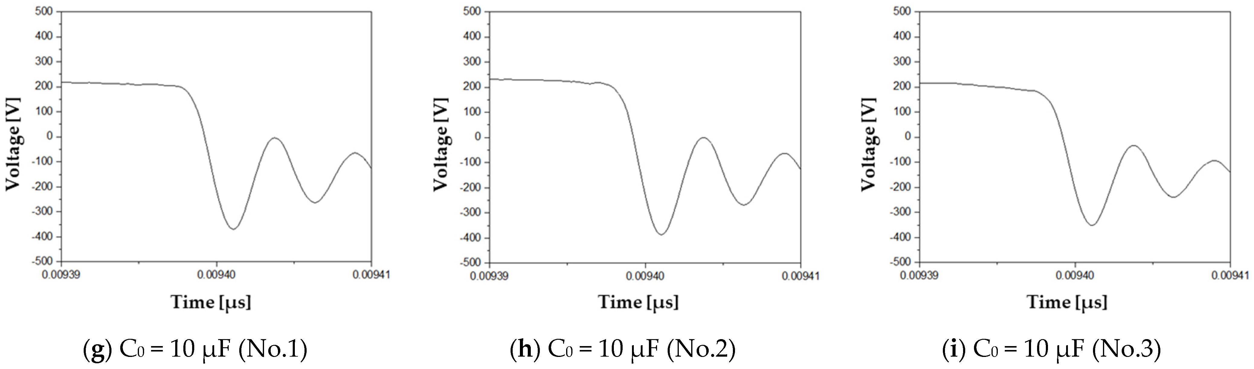
3.2. Disturbing Magnetic Field Test Results

Figure 14 shows the test setup to confirm the characteristics of the circuit breaker by disturbing the magnetic field. In order to apply a magnetic field to the arc extinguishment chamber of the circuit breaker, a core wound with an enamel wire is installed in the circuit breaker. A silicon steel plate-laminated core is used, and the current is applied to the 18 AWG enamel wire with 87 turns. The force acting on the disturbing magnetic field and the arc current is predicted using a magnetic equivalent circuit. The following equation shows the magnitude of the magnetic flux generated by the current applied to the coil.
ϕ = N I R t o t a l
Φ is the magnetic flux by an external magnetic field, N is the coil turn, I is the coil current, and Rtotal is the total magnetic resistance of the magnetic equivalent circuit. According to the equation, if the core is not saturated by the magnetic field, the magnetic flux by the magnetic field is proportional to the current applied to the coil. In addition, the force applied to the arc current is shown in the following equation.
f v = ( J × B ) + H d i v B
fv is the volume force density and is expressed in Equation (5) as the cross product of the current density (J) and magnetic flux density (B) and the product of the magnetic field (H) and divergence of B, as shown. In this paper, when 5A flows through the core, the maximum values of magnetic field and force are approximately 4 × 10 4 A/m and 52 mN, respectively. These values act in a direction that interferes with the motion of the arc current.
Figure 15 shows the short-circuit characteristics in the presence of disturbing magnetic fields. These results were summarized in Table 4.
The results are as follows. First, for t10, there is little difference with +0.01 ms. This means that the influence of disturbing magnetic fields on the Holm force and the Lorentz force of t10 is very little. In the case of the Holm force, the hardness of the material and the area of the electrode are not factors affected by the magnetic fields [21]. The Lorentz force may be affected by magnetic fields, but for the Lorentz force to be large, the reciprocating current path interval should be small, and for the Lorentz force to be greatly influenced by magnetic fields, the interval should be large. The two factors are inversely proportional. In fact, circuit breakers have small intervals, so the Lorenz force is insignificant.
In t21, it increases by +0.35 ms compared to no magnetic fields. These disturbing magnetic fields generate forces in a direction that disturbs the arc current moving toward the splitter plate. The increase in time in this period may also affect the subsequent period t32, leading to interruption failure.
In the case of t32, it is not as meaningful as in the case of t10. Disturbing magnetic fields do not affect arc extinguishment in this period. The increase/decrease ratios of periods t10, t21, and t32 of disturbing magnetic fields in preparation for the case of no magnetic fields are −0.27%, 8.56%, and 0.15%, respectively. t21 shows a significant change ratio even in no disturbing magnetic fields. It can be seen that this also increases the overall time by 4.08%.
Figure 16 shows dielectric recovery voltage (DRV) under disturbing magnetic fields.
Table 5 shows the values of dielectric recovery voltage (DRV) under disturbing magnetic fields. Each C0 value (0.47, 1, and 10 μF) shows the average voltage and average time. Using these voltages and times, Figure 17 shows the DRV V-t curve under distanced magnetic fields.
The results are as follows. The average time corresponding to each of the C0 values (0.47 μF, 1 μF, 10 μF) is 1.08 μs, 1.75 μs, and 4.73 μs, respectively. At ti, with and without disturbed magnetic fields, the DRVs are 320 V and 305 V, respectively. At tm, with and without disturbed magnetic fields, the DRVs are 382 V and 361 V, respectively. At tl, with and without disturbing magnetic fields, the DRVs are 491 V and 429 V, respectively.
Based on the case with no magnetic fields, the DRV change rates of disturbed magnetic fields are 4.92%, 5.82%, and 14.45% for ti, tm, and tl, respectively. This rate of change is approximately three times greater in the late period than in the early and medium periods. The initial DRV characteristics are affected by the cooling characteristics of the splitter plate, the temperature change of the arc current, and energy loss in the air. On the other hand, the DRV characteristics of the later stage are affected by the heat gas emission after arc extinguishing. This ionized heat gas is greatly affected by the magnetic field and is prevented from moving to the exhaust. For this reason, it is judged that there is a large difference in the late period (tl).

4. Conclusions

In this paper, an analysis of the short-circuit characteristics and dielectric recovery strength of the molded case circuit breaker according to external environment conditions is performed. The external temperature and disturbing magnetic fields are set as external environment conditions. The temperature results show that both short-circuit characteristics and dielectric recovery strength deteriorate as the temperature increases. The ratio of the value of 25 °C to 35 °C and 25 °C to 45 °C has similar values for both short-circuit characteristics and dielectric recovery strength. t10, t21, and t32 corresponding to short-circuit characteristics are 1.58, 1.53, and 1.79, respectively, and ti, tm, and tl, corresponding to dielectric recovery strength are 1.59, 1.69, and 1.53, respectively. In other words, when the external temperature increases from 25 °C to 45 °C, it can be seen that both short-circuit characteristics and dielectric recovery strength deteriorate at a similar rate. This shows a similar tendency to the case of the experiment conducted previously by changing the thermal conductivity of the splitter plate [14]. The second external environmental condition is disturbing magnetic fields. For this experiment, an external magnetic field is introduced in the direction in which the interruption of the circuit breaker was disturbed. As a result, the short-circuit characteristics only show a meaningful result at t21, and there is no significant difference in the other periods. However, if the distance between the current paths that generate the Lorentz force in other circuit breakers is increased, it is expected to show a difference at t10. The dielectric recovery strength shows a significantly larger difference in the latter time than in the initial time and the medium time. The ability of magnetic fields to interfere with the release of heat gases is evident. These external magnetic fields can be applied in various ways depending on the circuit breaker installation environment. The influence in one direction is dealt with in this paper. The external temperature and disturbing magnetic fields covered in this paper are not tested according to product standards. In addition, greater damage is expected due to the miniaturization of the environment in which the circuit breaker is installed and the complexity of peripheral devices. Based on this paper, it is expected that more performance evaluations of circuit breakers in various environments will be conducted.

Author Contributions

Data curation, Y.-M.C. and K.-A.L.; software, H.-J.P.; writing—original draft, Y.-M.C. and H.-J.P.; writing—review and editing, H.-J.L. and K.-A.L.; project administration, H.-J.L. and K.-A.L.; funding acquisition, H.-J.L. All authors have read and agreed to the published version of the manuscript.

Funding

This work was supported by the National Research Foundation of Korea (NRF) grant funded by the Korea government (MSIT) (NRF-RS-2022-00143178) and Basic Science Research Program through the National Research Foundation of Korea (NRF) funded by the Ministry of Education (NRF-2020R1I1A3069569).

Conflicts of Interest

The authors declare no conflict of interest.

References

  1. 60947-2; Low-Voltage Switchgear and Controlgear—Part 2: Circuit-Breakers. International Electrotechnical Commission: Geneva, Switzerland, 2019.
  2. 60947-1; Low-Voltage Switchgear and Controlgear—Part 1: General Rules. International Electrotechnical Commission: Geneva, Switzerland, 2020.
  3. Liu, Z.; Huang, S.; Zhao, C. Study on the Influence of Reignition on Electrical Life Distribution of Low-Voltage Circuit Breakers. IEEE Access 2021, 9, 91500–91511. [Google Scholar] [CrossRef]
  4. Szulborski, M.; Łapczyński, S.; Kolimas, Ł.; Zalewski, D. Transient thermal analysis of the circuit breaker current path with the use of fea simulation. Energies 2021, 14, 2359. [Google Scholar] [CrossRef]
  5. Szulborski, M.; Łapczyński, S.; Kolimas, Ł. Increasing Magnetic Blow-Out Force by Using Ferromagnetic Side Plates inside MCB. Energies 2022, 15, 2776. [Google Scholar] [CrossRef]
  6. Yang, W.; Zhang, P.; Zhang, B. Influence of High Altitude Environment on Thermal Performance of Miniature Circuit Breaker. In Proceedings of the 2021 IEEE 4th International Electrical and Energy Conference (CIEEC), Nanjing, China, 27–29 May 2021; pp. 1–6. [Google Scholar]
  7. Fu, R.; Bhatta, S.; Keller, J.M.; Zhang, Y. Assessment of Cable Length Limit for Effective Protection by Z-Source Circuit Breakers in DC Power Networks. Electronics 2021, 10, 183. [Google Scholar] [CrossRef]
  8. Bhatta, S.; Fu, R.; Zhang, Y. A New Method of Detecting and Interrupting High Impedance Faults by Specifying the Z-Source Breaker in DC Power Networks. Electronics 2020, 9, 1654. [Google Scholar] [CrossRef]
  9. He, J.; Wang, K.; Li, J. Numerical Study on Multiple Arcs in a Pyro-Breaker Based on the Black-Box Arc Model. Electronics 2022, 11, 1702. [Google Scholar] [CrossRef]
  10. Tapia, L.; Baraia-Etxaburu, I.; Valera, J.J. Design of a Solid-State Circuit Breaker for a DC Grid-Based Vessel Power System. Electronics 2019, 8, 953. [Google Scholar] [CrossRef] [Green Version]
  11. Dongkyu, S.; Golosnoy, I.O.; McBride, J.W. Experimental Study of Reignition Evaluators in Low-Voltage Switching Devices. IEEE Trans. Compon. Packag. Manuf. Technol. 2018, 8, 950–957. [Google Scholar]
  12. Miyara, R.; Nakadomari, A.; Matayoshi, H.; Takahashi, H.; Hemeida, A.M.; Senjyu, T. A Resonant Hybrid DC Circuit Breaker for Multi-Terminal HVDC Systems. Sustainability 2020, 12, 7771. [Google Scholar] [CrossRef]
  13. Kim, G.; Lee, J.S.; Park, J.H.; Choi, H.D.; Lee, M.J. A Zero Crossing Hybrid Bidirectional DC Circuit Breaker for HVDC Transmission Systems. Energies 2021, 14, 1349. [Google Scholar] [CrossRef]
  14. Cho, Y.M.; Lee, K.A. Experimental Study on Splitter Plate for Improving the Dielectric Recovery Strength of Low-Voltage Circuit Breaker. Electronics 2020, 9, 2148. [Google Scholar] [CrossRef]
  15. Rouder, J.N.; Engelhardt, C.R.; McCabe, S.; Morey, R.D. Model comparison in ANOVA. Psychon. Bull. Rev. 2016, 23, 1779–1786. [Google Scholar] [CrossRef] [PubMed] [Green Version]
  16. Hashemi, E.; Niayesh, K. DC Current Interruption Based on Vacuum Arc Impacted by Ultra-Fast Transverse Magnetic Field. Energies 2020, 13, 4644. [Google Scholar] [CrossRef]
  17. Dehui, C.; Xingwen, L.; Ruicheng, D. Measurement of the Dielectric Recovery Strength and Reignition of AC Contactors. IEICE Trans. Inf. Syst. 2005, 88, 1641–1646. [Google Scholar]
  18. Lee, K.A.; Cho, Y.M.; Lee, H.J. Circuit model and analysis of molded case circuit breaker interruption phenomenon. Electronics 2020, 9, 2047. [Google Scholar] [CrossRef]
  19. Dascal, A.A. Experimental studies to assess stainless steel high temperature hardness. Rev. Fac. Ing. Univ. Antioq. 2006, 38, 119–127. [Google Scholar]
  20. Cho, Y.-M.; Rhee, J.-H.; Baek, J.-E.; Ko, K.-C. Implementing a Dielectric Recovery Strength Measuring System for Molded Case Circuit Breakers. Int. J. Electr. Eng. Technol. 2018, 13, 1751–1757. [Google Scholar]
  21. Digpalsinh, P.; Mayur, G. Analysis and improvement in repulsive force of 630 A frame Moulded Case Circuit Breaker (MCCB). Int. Perspect. Sci. 2016, 8, 424–427. [Google Scholar]
Figure 1. Main effect plot according to material.
Electronics 11 03575 g001
Figure 2. Magnetic field effects on circuit breaker.
Electronics 11 03575 g002
Figure 3. Experiment circuit.
Electronics 11 03575 g003
Figure 4. Schematics of measurement points. (a) Short-circuit characteristics, (b) Dielectric recovery voltage.
Electronics 11 03575 g004
Figure 5. Test setup for temperature experiment.
Electronics 11 03575 g005
Figure 6. Short-circuit characteristics at 25 °C.
Electronics 11 03575 g006
Figure 7. Short-circuit characteristics at 35 °C.
Electronics 11 03575 g007aElectronics 11 03575 g007b
Figure 8. Short-circuit characteristics at 45 °C.
Electronics 11 03575 g008aElectronics 11 03575 g008b
Figure 9. BH as a function of temperature based on the value of 25 °C.
Electronics 11 03575 g009
Figure 10. Dielectric recovery voltage at 25 °C.
Electronics 11 03575 g010
Figure 11. Dielectric recovery voltage at 35 °C.
Electronics 11 03575 g011aElectronics 11 03575 g011b
Figure 12. Dielectric recovery voltage at 45 °C.
Electronics 11 03575 g012aElectronics 11 03575 g012b
Figure 13. DRV V-t curve according to temperature.
Electronics 11 03575 g013
Figure 14. Test setup for disturbing magnetic field experiment.
Electronics 11 03575 g014
Figure 15. Short-circuit characteristics under disturbing magnetic fields.
Electronics 11 03575 g015
Figure 16. Dielectric recovery voltage under disturbing magnetic fields.
Electronics 11 03575 g016
Figure 17. DRV V-t curve under disturbed magnetic fields.
Electronics 11 03575 g017
Table 1. Measurement result of DRV in previous paper [14].
Material
(Thermal Conductance) [kcal/°C]
Time
[μs]
Voltage
[V]
Steel
(62)
Initial Period1.1217
0.8189
1.2208
Medium Period3.1281
2.6266
2.3236
Later Period4.2311
5.0362
4.7347
Aluminum
(196)
Initial Period0.8314
0.5115
0.77309
Medium Period2.76371
1.76283
2.14362
Later Period3.92362
3.91380
3.90380
Copper
(320)
Initial Period0.65287
0.78327
0.78345
Medium Period1.88292
1.88371
2.18371
Later Period3.32336
3.52327
4.25415
Table 2. Short-circuit characteristics test results according to temperature.
TemperatureCategoryTest Number [V]AVG.
123456789
25 °Ct102.732.572.413.942.842.203.552.212.492.77
t214.174.364.622.884.294.833.345.024.684.24
t321.491.471.451.651.321.391.571.351.431.45
35 °Ct102.511.241.492.672.552.442.092.042.292.14
t214.985.445.754.224.404.485.105.014.884.91
t321.502.001.421.571.411.591.431.511.441.54
45 °Ct101.992.601.591.651.291.231.772.081.861.78
t215.054.405.295.565.745.815.415.045.175.27
t321.891.542.111.391.561.511.431.461.571.60
Table 3. Dielectric recovery voltage test results according to temperature.
TemperatureC0
[μF]
CategoryTest NumberAVG.
123
25 °C0.47tDRV [μs]0.961.231.011.06
VDRV [V]423386230346
1tDRV [μs]1.741.902.021.88
VDRV [V]368375411384
10tDRV [μs]4.374.534.634.51
VDRV [V]467491489482
35 °C0.47tDRV [μs]0.830.901.440.99
VDRV [V]318312209279
1tDRV [μs]1.791.871.831.83
VDRV [V]413429245362
10tDRV [μs]4.614.683.864.38
VDRV [V]399437376404
45 °C0.47tDRV [μs]0.621.200.570.79
VDRV [V]238169236214
1tDRV [μs]1.771.921.941.87
VDRV [V]369352338353
10tDRV [μs]4.254.594.534.45
VDRV [V]334435333367
Table 4. Short-circuit characteristics test results according to disturbing magnetic fields.
Magnetic FieldCategoryTest Number [V]AVG.
123456789
No magnetic fields
(I = 0 A)
t103.562.572.413.942.612.203.552.832.492.90
t213.334.364.622.884.624.833.344.254.684.10
t321.541.471.451.651.281.391.571.351.431.45
Disturbing magnetic fields
(I = 5 A)
t103.371.801.674.312.932.782.952.503.782.89
t213.695.145.192.734.644.594.575.024.504.45
t321.331.861.731.471.401.141.471.451.301.46
Table 5. Dielectric recovery voltage test results according to disturbed magnetic fields.
Magnetic fieldC0
[μF]
CategoryTest NumberAVG.
123
No magnetic field
(I = 0 A)
0.47tDRV [μs]0.961.281.011.08
VDRV [V]423465230372
1tDRV [μs]1.742.052.021.93
VDRV [V]368384411387
10tDRV [μs]4.884.534.634.68
VDRV [V]498491489492
Disturbing magnetic field
(I = 5 A)
0.47tDRV [μs]1.261.330.651.08
VDRV [V]348315349337
1tDRV [μs]1.131.641.961.57
VDRV [V]298384410364
10tDRV [μs]4.694.565.134.79
VDRV [V]460399427428
Publisher’s Note: MDPI stays neutral with regard to jurisdictional claims in published maps and institutional affiliations.

