Article

Study on the Law and Mechanism of the Third-Order Intermodulation False Alarm Effect of the Stepped Frequency Ranging Radar

National Key Laboratory of Electromagnetic Environment Effects, Army Engineering University Shijiazhuang Campus, Shijiazhuang 050003, China
*
Author to whom correspondence should be addressed.
Electronics 2022, 11(22), 3722; https://doi.org/10.3390/electronics11223722
Submission received: 18 October 2022 / Revised: 9 November 2022 / Accepted: 10 November 2022 / Published: 13 November 2022
(This article belongs to the Section Circuit and Signal Processing)

Abstract

:
In order to improve the radar’s electromagnetic protection ability, it is essential to master the law of the false alarm effect of the radar’s out-of-band third-order intermodulation electromagnetic radiation, starting from the circuit field-circuit coupling mechanism, and the mechanism of the third-order intermodulation false alarm effect is analyzed. Taking a stepped frequency ranging radar as the research object, the absolute level value of the false alarm signal is selected as the sensitive criterion of the false alarm effect. The dual-frequency electromagnetic false alarm interference effect is carried out by using the method of the differential mode injection equivalent substitution electromagnetic radiation. The results show that the dual-frequency electromagnetic interference will cause the radar to generate the third-order intermodulation false alarm signal with the random position and waveform spreading. Under a certain interference intensity, the level of the third-order intermodulation false alarm signal increases with the increase of the interference field strength. With the continuous increase of the interference field strength, the fifth-order intermodulation false alarm signal gradually appears. The imaging mechanism, the waveform characteristics, and the level change law of the fifth-order intermodulation false alarm target, are similar to the third-order intermodulation false alarm target, and its position is also random. The maximum third-order intermodulation false alarm signal can reach 18 dBmV, indicating that the radar is sensitive to the out-of-band intermodulation electromagnetic interference.

1. Introduction

With the continuous development of science and technology, the high density of frequency equipment makes the battlefield of the electromagnetic environment increasingly complex, and the complex electromagnetic environment leads to poor access to combat information and difficult to command and control, which leads to the reduction of combat effectiveness [1,2]. The radar is an important component of air defense systems, offensive missile guidance, and battlefield surveillance, and without an adequate electromagnetic protection performance, it is difficult to perform its effectiveness [3]. In actual combat, the radar faces many electromagnetic radiation sources internally and externally. Due to the nonlinearity of the internal circuit of the receiver, a new intermodulation frequency component will be generated between the multi-frequency electromagnetic interference (EMI), if this component falls into the sensitive frequency band of the equipment under test (EUT), it will affect the image of the receiver. Therefore, it is necessary to study the interference effect of the multi-frequency inter-modulation (IM) EMI on the radar.
In recent years, domestic and foreign scholars have carried out a series of related studies for the equipment of multi-frequency EMI. References [4,5] analyzed the adverse effects of the out-of-band EMI on the radar, but did not involve the out-of-band multi-frequency of the IM-EMI components. Xu G M and Liu H analyzed the third-order intermodulation interference signal, generated by the multi-frequency interference signal inside the power amplifier and simulated the signal [6,7]. Aiming at the multi-frequency IM problem of the ship communication system, Li J X established the corresponding mathematical model for the IM problem of the naval communication system [8]. Yaping Wang and Wei Li systematically studied the in-band and out-of-band multi-frequency electromagnetic blocking interference mechanism of radio stations and established an in-band multi-frequency, and an out-of-band intermodulation, a non-intermodulation blocking effect models and interference prediction and evaluation methods [9,10]. In addition, the out-of-band multi-frequency EMI effect experiments were carried out on navigation receivers by Hongze Zhao and Jianyong Zheng, to elucidate the interference mechanism of the out-of-band second-order IM-EMI and the third-order IM-EMI to navigation receivers and gave the interference assessment method of the IM blocking electromagnetic radiation effect on the navigation receiver [11,12].
For the radar electromagnetic radiation effect, Kang [13] summarized the law of dual-frequency non-intermodulation blocking interference by carrying out radar dual-frequency CW-EMI tests. Kang W. C and Liu H analyzed the influence of the multi-frequency intermodulation interference signal on the useful signal of the receiver [7,14]. Compared with the EMI of the frequency equipment, there is less research on the radar’s false alarm interference. Research on the radar’s false target is mostly aimed at information interference, and there is relatively less research on the non-information interference [15,16]. In the test of the radar EMI effect, it is found that when the interference frequency falls into the filter bandwidth, it will not only produce a blocking effect on the radar, but will also cause the radar to produce a false target response, which seriously affects the effective judgment of the battlefield situation [17,18]. In addition, the out-of-band dual-frequency EMI also causes the radar to produce a false target response similar to the in-band single frequency, therefore, it is necessary to study the radar’s dual-frequency false target response mechanism. The team has systematically conducted experiments on the false alarm effect of the radar’s in-band single-frequency and dual-frequency EMI in the early stage, and elucidated the false alarm interference law and mechanism of action of the radar’s single-frequency, dual-frequency, and second-order IM-EMI [18], but did not analyze the third-order intermodulation false alarm (IMFA-3) signal with a strong out-of-band intermodulation ability. Therefore, this paper takes the stepped frequency ranging radar as the research object, based on the circuit’s nonlinear characteristics and the radar’s imaging principle, theoretically analyzes the out-of-band third-order intermodulation false alarm signal sensitivity parameter changes and the imaging characteristics, and reveals the out-of-band IMFA-3 interference law and effect mechanism. The theoretical derivation and experiments are combined to give the IMFA-3 signal sensitivity criterion, to carry out the radar’s dual-frequency electromagnetic interference effect test, and summarize the law of the IMFA-3 signal, which provides the theoretical support for the subsequent establishment of the radar equipment’s electromagnetic environment effect prediction and evaluation.

2. Interference Theory Analysis

2.1. Third-Order Intermodulation False Alarm Level Interference Mechanism

In the process of signal processing, a power series is often used to characterize the ‘input-output’ characteristics of nonlinear circuits [18], that is:
u o = a 0 + i = 1 n a i u i i
where ai is the nonlinear coefficient at each level. When the value of i is 2 or 3, the system has produced the interactive modulation, blocking, and harmonics, and in the analysis of the general i is 3, as a benchmark to analyze the nonlinearities caused by the output amplitude, frequency, and other changes in parameters. As the input signal further increases, the value of i is 3, which cannot approximate the degree of the nonlinear distortion of the system, and the higher-order terms are needed [13].
Equipment by the dual-frequency EMI f1, f2, the RF front-end input signal is:
u i ( t ) = u 1 ( t ) + u 2 ( t ) = U 1 cos 2 π f 1 t + U 2 cos 2 π f 2 t = A 1 E 1 cos 2 π f 1 t + A 2 E 2 cos 2 π f 2 t
where A1 and A2 denote the frequency related coefficients. E1, E2, and U1, U2 are the field strength and level amplitude corresponding to the dual-frequency interference f1 and f2. Table 1 lists the frequency components and their output amplitudes that fall into the band when i is taken as value 5.
Take the third-order intermodulation interference signal as an example, because the IMFA-3 signal comes from the mutual mixing of the out-of-band dual frequency, it is independent of the useful signal.
Combined with Table 1, the third-order intermodulation interference signal generated by the out-of-band dual-frequency interference f1 and f2 (default frequency is 2f1f2), can be expressed as:
u IM 3 ( 2 f 1 f 2 ) = 3 4 a 3 U 1 2 ( f 1 ) U 2 ( f 2 ) cos [ ( 2 f 1 f 2 ) t ]
Ignore the initial phase, if the receiver RF front-end performance is not good or the out-of-band dual-band interference field strength increases to a certain extent, the device’s nonlinearity will cause the dual-band interference signal to generate the third-order intermodulation component. If the IM component falls into the false alarm sensitive band, in addition to the useful signal, it will cause the system misjudgment and generate a false alarm target, and the target is defined as the IMFA-3 signal. It can be seen from Equation (3) that the amplitude increases with the increase of the input signal, and the corresponding gain of the corresponding IMFA-3 signal at this time is
{ G ( 2 , 1 ) = 3 4 k 3 U 1 U 2 G ( 2 , 2 ) = 3 4 k 3 U 1 2
G(2,n) (n = 1,2) represents the gain of the interference component when the out-of-band dual-frequency interference acts. When the interference field strength is weak, the system is in a weakly nonlinear state and the IMFA-3 signal level value increases with the enhancement of the interference field strength.
When the system’s nonlinearity increases, the influence of the higher-order terms cannot be ignored [13]. At this time, i takes 5 in Equation (1) to obtain the corresponding IMFA-3 signal:
u IM 3 2 f 1 f 2 = 3 4 a 3 U 1 2 U 2 cos 2 f 1 f 2 t + a 5 U 1 U 2 5 4 U 1 3 + 3 8 U 1 U 2 2 cos 2 f 1 f 2 t
It can be seen from Equation (5) that the amplitude of the IMFA-3 signal increases with the increase of the dual-frequency interference field strength. Due to k3·k5 ˂ 0, k5 inhibits the decrease of the signal, its growth rate is reduced. Due to the different proportions of the two interference signals U1 and U2, the IMFA-3 signal has different growth rates with the two interference components. Specific analysis should be combined with the specific situation.
In addition, according to Table 1, the existence of the a5 term, not only has an impact on the IMFA-3 signal, but it also generates the fifth-order intermodulation false alarm (IMFA-5) component. Taking 3f1 − 2f2 as an example, the expression is as follows.
u IM 5 ( 3 f 1 2 f 2 ) = 11 16 a 5 U 1 3 U 2 2
Due to the complex internal structure of the radar, there are multiple nonlinear devices cascaded, and not a single level of mixing. With the same third-order intermodulation signal, the amplitude of the IMFA-5 signal increases with the increase of the interference signal. Due to the different proportions of the two interference components in the third-order and IMFA-5 signals, the change rate of the corresponding IM false alarm signal with a single component is different, and followed by a continuous increase in the intensity of the interference field, its level increase rate is reduced. When the degree of nonlinear distortion increases, further analysis is performed with the help of experiments.

2.2. Intermodulation False Alarm Target Characteristics

Combined with the imaging mechanism of the stepped frequency ranging radar signal [19,20], the uncertainty of the false alarm signal is analyzed. For the convenience of the analysis, the echo signal and the third-order intermodulation signal amplitude information, generated by the dual frequency are ignored. When a static target is detected under a dual-frequency EMI, the RF front end receives the signal.
{ u i ( t ) = u s ( t ) + u j ( t ) u s ( t ) = k = 0 N 1 r e c t ( t k t r t r 2 2 R c t r ) exp [ j ( 2 π ( f l + k Δ f * ) ( t 2 R c ) + θ k ) ] u j ( t ) = exp [ j ( 2 π f 1 t + θ 1 ) ] + exp [ j ( 2 π f 2 t + θ 2 ) ]
where us(t) and uj(t) are the useful signal (target echo signal) and the interference signal, respectively; N is the number of stepped frequency steps; tr is the single stepped hopping time; fl is the radar starting frequency; f1 and f2 are the dual-frequency interference frequency components, respectively; Δ f * is the stepped frequency and R is the target distance. It is assumed that θk, θ1, and θ2 are the initial phases corresponding to the transmitted signal and the dual-frequency interference signal, respectively.
It is assumed that the local oscillation signal can be expressed as
u L ( t ) = k = 0 N 1 r e c t ( t k t r t r 2 t r ) exp [ j ( 2 π ( f l + k Δ f * ) t + θ k ) ]
Combined with Table 1, it can be seen that when the third-order intermodulation interference component, generated by the dual frequency, falls into the working frequency band of the filter, it will be processed together with the useful signal by mixing, amplifying, filtering, sampling, and the inverse Fourier transform, that is:
{ u s ( t ) u L ( t ) f i l t e r   a m p l i f i c a t i o n exp [ j ( 2 π ( f l + k Δ f * ) 2 R c ) ] u IM 3 ( t ) u L ( t ) f i l t e r   a m p l i f i c a t i o n exp [ j ( 2 π ( f l 2 f 1 + f 2 ) t + k Δ f * t + ( θ k 2 θ 1 + θ 2 ) ) ]
Assuming that the sampling time tk = ktr + td, 0 < td < tr, the useful signal after acquisition can be expressed as:
u s ( k ) = u s 1 ( k ) + u s 2 ( k ) = e j ( 4 π R f l c ) e j ( 4 π R Δ f * c k )
In the above formula, the useful signal target range profile is obtained by the inverse Fourier transform of exp ( j 4 π R Δ f * c k ) [10], that is:
| IFFT [ u s 2 ( k ) ] | = 1 N k = 0 N 1 u s 2 ( k ) e j 2 π k n N
Let l = R o u n d ( 2 N Δ f * R / c ) , using the Euler formula to further calculate the above equation, the following expression is obtained:
| IFFT [ u s 2 ( k ) ] | = 1 N k = 0 N 1 u s 2 ( k ) e j 2 π k n N = 1 N k = 0 N 1 e j 2 π k ( n l ) N = 1 N 1 e j 2 π k ( n l ) 1 e j 2 π k ( n l ) N = 1 N e j π ( n l ) 1 e j π ( n l ) N e j π ( n l ) e j π ( n l ) e j π ( n l ) N e j π ( n l ) N = 1 N sin π ( n l ) sin ( π ( n l ) N ) e j π ( N 1 ) ( n l ) N = sin c ( n l ) sin c ( n l ) N e j π ( N 1 ) ( n l ) N
It can be seen from (12) that the target imaging is maximized at n = l, and the detected target position R = c n / 2 N Δ f * is obtained.
Similarly, the IMFA-3 signal sampling sequence is obtained as follows:
u IM 3 ( k ) = e j 2 π ( f l t r 2 f 1 t r + f 2 t r + Δ f * t d ) k e j 2 π ( f l 2 f 1 + f 2 ) t d e j 2 π Δ f * t r k 2 e j ( θ k 2 θ 1 + θ 2 )
The IMFA-3 signal target imaging is analyzed according to Equation (13). The first exponential term contains the first power of k, which can be regarded as a frequency-domain signal with time point 1 and a linearly varying frequency, and this term will produce a false alarm target with a fixed position by the IFFT transform processing. The third exponential term in Equation (13) contains the square of the variable k, which will make the interference signal energy disperse, resulting in the IMFA-3 target waveform to broaden and the energy to disperse. The second exponential term contains the delay time td term, which has different effects on the position of the false alarm target. In the next analysis, the position of the IMFA-3 signal, that is, make y 1 ( k ) = e j 2 π m / N , where m = Round[N(fltr + Δf*td − 2f1tr + f2tr)], the inverse Fourier transform is performed on the linear term in Equation (13):
| IFFT [ u IM 3 ( k ) ] | | IFFT [ y 1 ( k ) ] | = | sin c ( n m ) sin c n m N |
when m = l, the false alarm signal position:
R IM 3 = c ( f l 2 f 1 + f 2 ) t r + c Δ f * t d 2 Δ f *
From Equation (15), it is known that the position of the IMFA-3 signal is related to the interference frequency offsets, the local oscillation frequency, the step frequency, the hopping frequency time, and the sampling moment. If the frequency hopping time tr and step frequency Δf* are certain, the delay time td in the acquisition moment tk = ktr + td is uncertain, which will also make the false alarm signal uncertain. In the actual imaging, the actual value of the false alarm target distance should also be combined with the selection of the radar signal parameters (tr and Δf*) to determine whether there is distance redundancy and other related information [19,20,21]. If the radar signal parameters meet the tight constraint conditions, the unambiguous distance, corresponding to the sub-period of the transmitting signal is rτ = ctr/2. Equation (15) is further derived to obtain the position expressed in the real measurement of IMFA-3.
R IM 3 = R IM 3 r τ Floor ( R IM 3 r τ )
where RIM3 represents the final theoretical value of IMFA-3, Floor ( x ) is the downward integral function.
Similarly, the IMFA-5 target characteristics and their positions are analyzed, and the five-order intermodulation false alarm signal, after sampling, is obtained by combining Equations (13) and (15):
u IM 5 ( k ) = e j 2 π ( f l t r 3 f 1 t r + 2 f 2 t r + Δ f * t d ) k e j 2 π ( f l 3 f 1 + 2 f 2 ) t d e j 2 π Δ f * t r k 2 e j ( θ k 3 θ 1 + 2 θ 2 )
The existence of k2 in the above equation makes the fifth-order intermodulation signal appear as a waveform spreading at the display terminal, and the inverse Fourier processing is performed on the above equation, let m = R o u n d [ N ( f l t r + Δ f * t d 3 f 1 t r + 2 f 2 t r ) ] , when m = l , the position of the IMFA-5 is obtained:
{ R IM 5 = c ( f l 3 f 1 + 2 f 2 ) t r + c Δ f * t d 2 Δ f * R IM 5 = R IM 5 r τ Floor ( R IM 5 r τ )
where RIM5 represents the theoretical final value of the IMFA-5 signal. According to the above analysis, the IMFA-5 is similar to the IMFA-3, and the distance of the target is related to the interference frequency offsets and the sampling moment.

3. Intermodulation False Alarm Effect Test

3.1. Build the Electromagnetic Radiation Test Platform

The working frequency band of the equipment under test (EUT) is f0 ± 100 MHz (f0 is the center frequency). Under the existing conditions in the laboratory, the electromagnetic irradiation is difficult to meet the demand of the third-order intermodulation generating for the test equipment, so the out-of-band IMFA-3 test is conducted on the test equipment by using the method of the equivalent substitution of the electromagnetic radiation by the differential mode injection [18]. Secondly, in order to eliminate the influence of the intermodulation component produced by the nonlinearity of the microwave power amplifier on the receiver, two interference systems were used in the experiment. The flow chart of the test system is shown in Figure 1. The main specific parameters of the equipment are as follows: the signal generator uses Ceyear1435 F, which can generate a 9 kHz~40 GHz microwave signal. The power amplifier uses AR 200 T, the working frequency band is 7.5~18 GHz, and the maximum output power is 200 W. The directional coupler is matched with the power amplifier, and the coupling degree of the forward power monitoring port is 50 dB. The spectrum analyzer uses Ceyear company’s 4204 G. The target uses a horn antenna. Combined with GJB8848-2016 [22], the output signal of the signal generator is amplified by the power amplifier and is synthesized by the combiner, and the interference signal is injected directly into the receiver’s RF front-end by the injection module. The spectrum meter monitors the final injection of the interference power into the RF front end.
Adjusting the frequency offsets of the two interference components, when the out-of-band dual-frequency interference is close to the working frequency and the interference intensity increases to a certain degree, a false alarm signal will appear, as shown in Figure 2. It can be seen from Figure 2 that the IMFA-3 signal broadens and the energy disperses. According to the team’s previous analysis of the in-band single-frequency false alarm signal [18], it can be seen that the IMFA-3 signal is similar to the in-band single-frequency false alarm signal waveform.

3.2. Third-Order Intermodulation False Alarm Signal Stability Test

It is necessary to adjust the different interference frequency offsets, to keep the interference field strength constant, making multiple measurements of the IMFA-3 signal, measuring and recording the absolute level of the IMFA-3 signal, as shown in Table 2. Where, the distance is denoted by RIM3, and the absolute level value of the IMFA-3 signal is denoted by UIM3.
It can be seen from Table 2, that under different interference frequency offset combinations, the position of the IMFA-3 signal is not fixed and presents a randomness, combined with Equation (9), the reason for this phenomenon is due to the effect of the quadratic phase. The test data of the absolute level of the IMFA-3 signal is relatively stable, and the data repeatability is good. Under the same interference frequency offset, the IMFA-3 level remains constant. According to the Formula (2), the amplitude of the signal depends on the field strength of the dual-frequency interference field, and the theoretical results are consistent with the experimental results. In addition, it can be seen from Table 2 that the interference frequency offsets combination is constant, the interference component increases, and the absolute level of the IMFA-3 increases, so the signal amplitude (absolute level) is used as the IMFA-3 effect parameter.

3.3. Relationship between the Third-Order Intermodulation False Alarm Level and the Radiation Field Strength

To simplify the test process as much as possible, we take into account the filter on both sides of the sensitive characteristics. The typical interference frequency points are selected to make the generated third-order intermodulation frequency (2Δf1 − Δf2) fall into the central frequency point. So we select the combination of −0.09 GHz, −0.18 GHz and the combination of −0.18 GHz, −0.36 GHz, and the other side selects the 0.09 GHz, 0.18 GHz frequency combination.
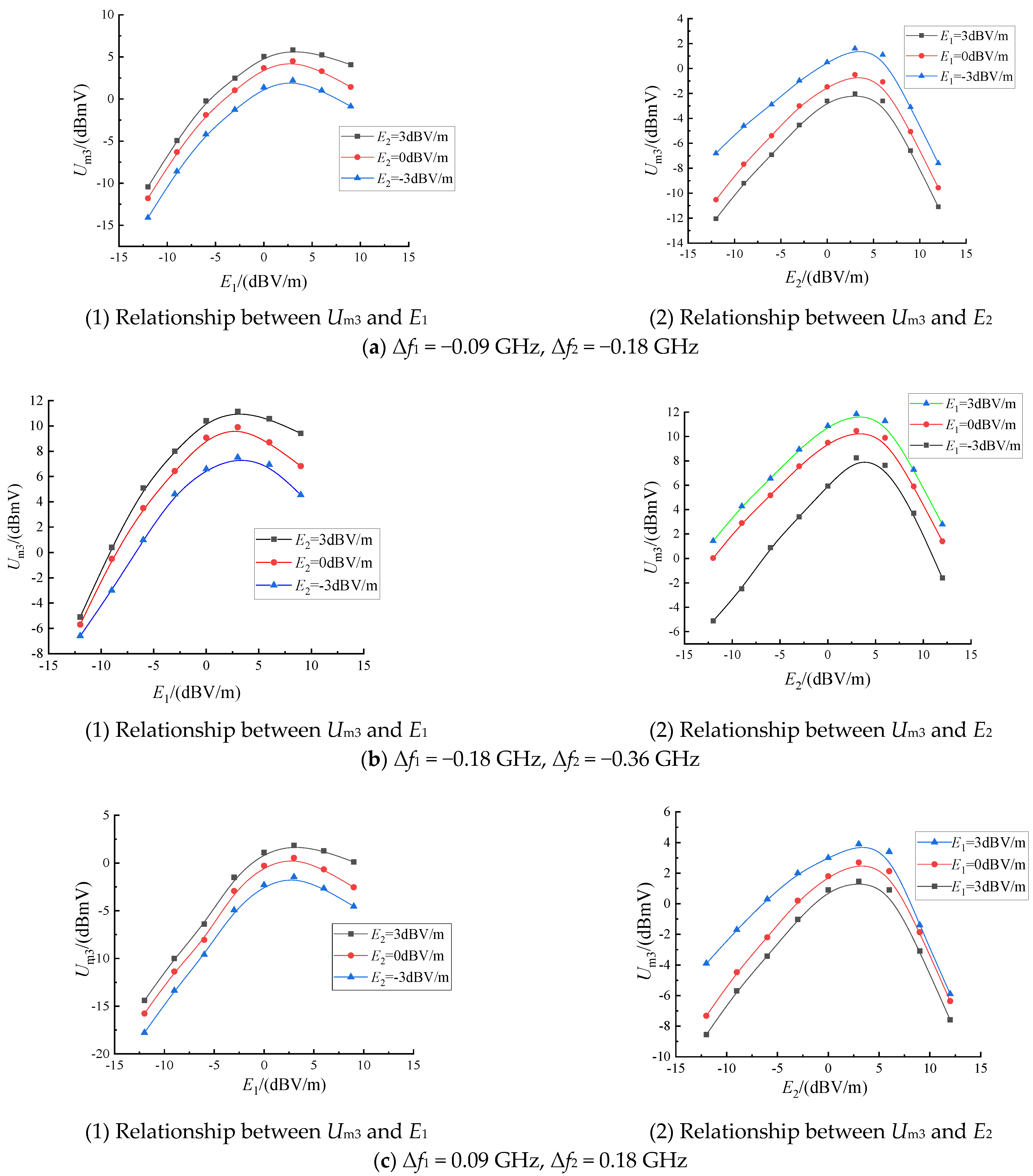
Following the selection of the interference frequency points, we adjust the dual-frequency interference strength to make one of the interference field strengths E1 or E2 constant, and we adjust the other interference field strength E2 or E1, we record the IMFA-3 signal amplitude Um3 and the results are shown in Figure 3.
It can be seen from Figure 3:
(1) Comparing (a) and (c) in Figure 3, regardless of the combination of the positive and negative frequency offsets of the dual-frequency interference, when fixed, an interference field strength E1 or E2, the IMFA-3 level has the same change trend as the other interference field strength E1 or E2, showing a trend of ‘first increase and then decrease’, indicating that the bandwidth of the RF front-end filter of the EUT is approximately symmetric. When the product of the radiation field strength is relatively small, one of the interferences remains constant, and the IMFA-3 level increases with the increase of another interference and gradually reaches the maximum. When the interference continues to increase, Um3 shows a downward trend, and k5 will suppress the rising trend of the false alarm signal.
(2) Comparing (a) and (b) in Figure 3, it can be seen that the larger the dual-frequency interference frequency offset, the larger the IMFA-3 signal level, and the more obvious the performance. Combined with the single-frequency electromagnetic blocking interference and false alarm interference sensitivity threshold test, it is known that when the dual-frequency interference frequency offsets Δf1 = −0.09 GHz and Δf2 = −0.18 GHz, the interference frequency point is outside the single-frequency electromagnetic false alarm interference band (±60 MHz). However, it is in the single-frequency electromagnetic blocking sensitive band (±180 MHz), indicating that the closer the dual-frequency interference frequency point is to the working band, that the test equipment’s single-frequency blocking interference on the IMFA-3 signal has a certain impact.
(3) The IMFA-3 frequency is certain, the interference field strength component E1 or E2 changes from −15 dBV/m to 0 dBV/m, and the combination of the dual-frequency interference frequency offset is different, and the range of the Um3 is different, indicating that the filter has different suppression effects on the different frequency offset interferences.
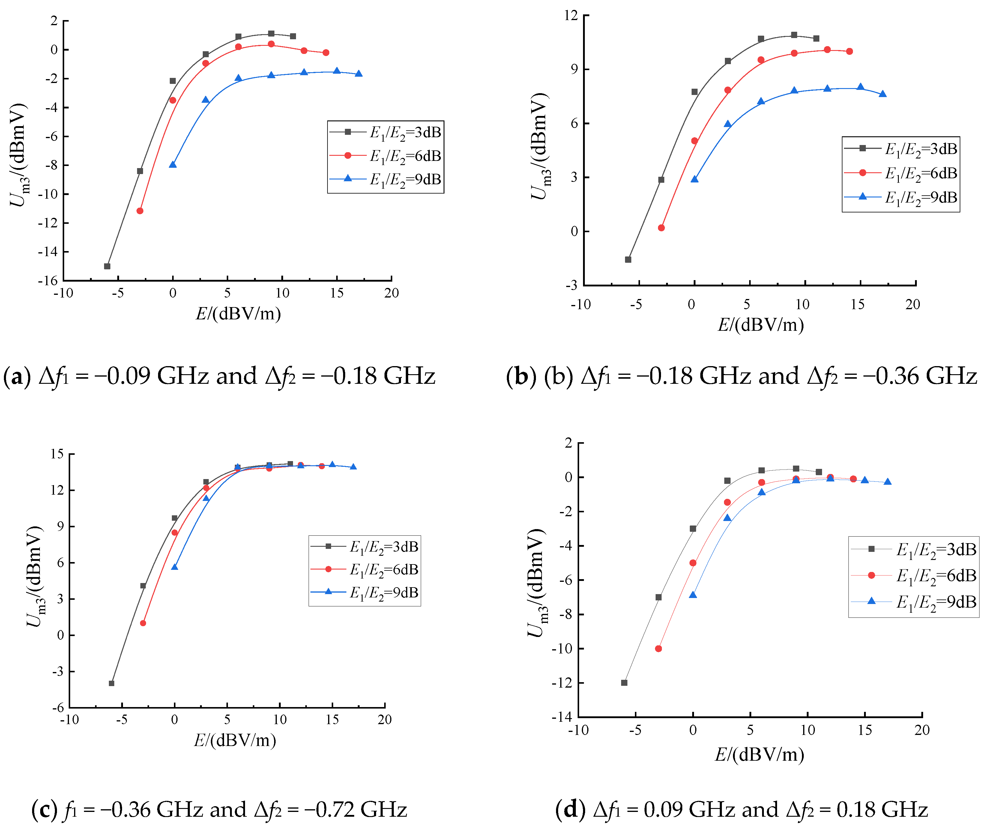
Similarly, when the dual-frequency radiation interference changes in the same proportion, the IMFA-3 signal amplitude changes, as shown in Figure 4.
The following conclusions can be drawn from Figure 4: (1) Comparing (a) and (d) in Figure 4, it can be seen that, regardless of whether the dual-frequency interference frequency offset is positive or negative, the variation of the IMFA-3 signal with the dual-frequency interference field strength is basically the same: when the interference field strength is small, the Um3 increases approximately linearly, and then the Um3 gain decreases, showing an approximately stable trend. (2) Comparing (a), (b) and (c) in Figure 4, under the same interference field strength, the farther the dual-frequency interference frequency offsets from the center frequency, the larger the measured IMFA-3 level value. (3) Comparing Figure 4b with Figure 3b, it can be seen that the amplitude of the IMFA-3 signal decreases with the increase of the single interference field strength in the range of 5 dBmV~15 dBmV. When the two interference components change in the same proportion, the downward trend is suppressed, making it gradually reach a stable value. (4) The out-of-band single-frequency does not produce a false alarm signal, and when the out-of-band dual-frequency works at the same time, the nonlinearity of the system produces a IMFA-3 signal. The maximum amplitude of the signal measured under the existing conditions can reach 18 dBmV.

4. IMFA-5 Signal Stability Test

The purpose of this experiment is to verify the importance of the k5 term, the existence of the k5 term means the existence of the IMFA-5, and the test configuration and method are the same as the third-order. During the test, it was found that, under the existing test conditions, limited by the input power of the power synthesizer, there are only a few points in the record of the seventh-order intermodulation false alarm signal, so the IMFA-5 as an example for the verification, test frequency point selection, as far as possible, so that the fifth-order falls into the band, the third-order falls into the out-of-band. At this time, the IMFA-5 is the main research object, and selection of the double-frequency interference frequency offsets Δfj1 = −0.28 GHz and Δfj2 = −0.42 GHz. The relationship between the measured IMFA-5 level and the variation of the interference component is shown in Table 3.
According to Table 3, it can be seen that the change law of the IMFA-5 level with the single interference field strength is similar to that of the IMFA-3 level with the single interference field strength, both of which increase first and then decrease. The position of the IMFA-5 signal is the same as that of the IMFA-3 signal, which shows randomness.
Similarly, when the two interference components increase at the same time, the IMFA-5 signal test data are shown in Table 4.
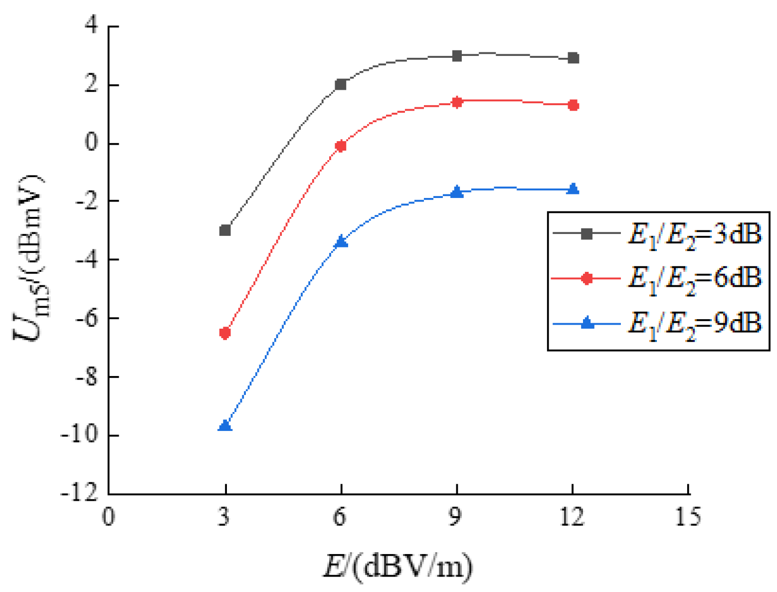
For the convenience of the analysis, the level change law is shown in Figure 5.
It can be seen from Figure 5, that when the interference field strength increases to a certain extent, the IMFA-5 signal gradually appears. Under a certain field strength, the amplitude variation is similar to the IMFA-3 and gradually increases with the increase of interference field strength. When the interference field strength is further increased, the nonlinear degree of the system is deepened, and the amplitude variation of the signal is the result of the interaction of intermodulation components.

5. Conclusions

In order to improve the electromagnetic protection ability of the radar, this paper discusses the mechanism of the IMFA-3 signal and the IMFA-5 signal, from the principle of the circuit field-circuit coupling. Theory and experiment are combined to systematically study the law of the out-of-band IMFA-3 effect. The conclusions are as follows.
  • The absolute value of the intermodulation false alarm target level is used as a sensitive criterion of the intermodulation false alarm interference of the tested radar.
  • The law of the IMFA-3 effect outside the radar band is studied, including the change of the single interference field strength and the synchronous change of the two-component field strength. If one interference field strength is constant, the third-order intermodulation signal level increases with the other interfering field strength, showing a trend of increasing and then decreasing. If the interference components change in the same proportion, the third-order intermodulation signal level increases with the increase of the interference field strength, but the rate of increase gradually decreases until it reaches a stable value.
  • As the interference field strength continues to increase, the influence of the IMFA-5 signal on the IMFA-3 cannot be ignored. The IMFA-5 interference effect test verifies the correctness of the theoretical analysis.
  • The out-of-band single frequency does not generate false alarm signals, but when the out-of-band dual frequency acts simultaneously, the nonlinear generation of the system will produce IMFA signals with a random position and waveform expansion, which affects the accuracy of the detected target level, which can reach a level value of 18 dBmV. Since the EUT is sensitive to the out-of-band IMFA interference, the focus is on the intermodulation of the false alarm modeling and the anti-interference processing in the subsequent study.

6. Discussion

In the research process of the out-of-band intermodulation interference of the radar equipment, it is found that the third-order intermodulation signal with an interference frequency close to the center frequency, has the greatest influence. The third-order intermodulation signal originates from the nonlinear response of the signal processing circuit of the radar equipment to the multi-frequency signal. When the third-order intermodulation frequency component falls into the sensitive working band of the test equipment, the signal is the same as the single-frequency signal in the band, resulting in the IMFA-3 of the test equipment. The IMFA-3 interference will reduce the critical interference field strength value to a certain extent, and the uncertainty of its position will affect the accuracy of the radar detection of the useful signals. Therefore, this paper analyzes the characteristics of the IMFA-3 signal, from the principle of the field linearity coupling, summarizing and generalizing the law between the sensitive parameters of the IMFA-3 signal and the interference field strength. The following work focuses on the prediction and evaluation method of the IMFA-3 interference effect, establishes the equation relationship between the sensitive parameters and the interference field strength, and gives the evaluation process of the IMFA-3 interference, which provides the theoretical support for improving the adaptability of the radar electromagnetic environment.

Author Contributions

X.D. conceived of the study, designed the study, and wrote the manuscript. G.W. provided guidance on the ideas and the mathematical treatment. X.P. and H.W. compiled the experimental data. H.Z. assisted in the editing of manuscripts. All authors have read and agreed to the published version of the manuscript.

Funding

This work was supported by the National Science Foundation of Key National Defense Basic Research projects (41409030301).

Data Availability Statement

The authors confirm that the data and the materials supporting the findings of this study are available within the article.

Conflicts of Interest

The authors declare no conflict of interest.

References

  1. Zhang, Z.; Xue, Y.T.; Ma, R.Q. An easy-implemented confidence filter for signal processing in the complex electromagnetic environment. Microelectron. Reliab. 2018, 88–90, 225–229. [Google Scholar] [CrossRef]
  2. Liu, S.H.; Wu, Z.C.; Zhang, X.J. Effect of electromagnetic environment and its development trend. Chin. J. Natl. Def. Technol. 2008, 29, 1–6. [Google Scholar]
  3. Hong, Z.T. Electromagnetic compatibility design of the computer circuits. J. Phys. Conf. Ser. 2018, 976, 19–21. [Google Scholar]
  4. Kashmoola, M.; Alsaleem, N. Model of Dynamics of the Grouping States of Radio Electronic Means in the Problems of Ensuring Electromagnetic Compatibility. East. Eur. J. Enterp. Technol. 2019, 6, 12–20. [Google Scholar] [CrossRef]
  5. Zhao, B.; Huang, L.; Zhang, J.H. Single channel SAR deception jamming suppression via dynamic aperture processing. IEEE Sens. J. 2017, 17, 4225–4230. [Google Scholar] [CrossRef]
  6. Xu, G.; Liu, T.; Ye, Y.; Zhang, X. Hybrid harmonic-intermodulation distortion behavioral model for shortwave power amplifiers. Int. J. RF Microw. Comput. Aided Eng. 2019, 29, e21718. [Google Scholar] [CrossRef]
  7. Liu, H. Impact of Nonideal Auxiliary Current Profile on Linearity of Microwave Doherty Amplifiers: Theory and Experiments. IEEE Trans. Circuits Syst. 2022, 69, 2325–2338. [Google Scholar] [CrossRef]
  8. Li, J.X. Evaluation Method for the Intermodulation Interference in an Integrated Shipboard Communication System. Chin. J. Ship Res. 2014, 9, 116–120. [Google Scholar]
  9. Li, W.; Wei, G.H.; Pan, X.D. Electromagnetic compatibility prediction method under the in-band interference environment. IEEE Trans. Electromagn. Compat. 2018, 60, 520–528. [Google Scholar] [CrossRef]
  10. Wang, Y.; Wei, G.; Li, W. Mechanism modeling and verification of receiver with in-band dual-frequency blocking jamming. Trans. Beijing Inst. Technol. 2018, 38, 709–714. [Google Scholar]
  11. Wei, G.; Zheng, J. A Model for Predicting Second-Order Intermodulation Low-Frequency Blocking Effects. IEEE Trans. Electromagn. Compat. 2022, 64, 348–358. [Google Scholar] [CrossRef]
  12. Zhao, H.Z.; Wei, G.H.; Du, X.; Zheng, J.; Li, M. Analysis of third-order intermodulation blocking effect for satellite navigation receiver. Chin. J. Syst. Eng. Electron. 2020, 44, 1336–1342. [Google Scholar]
  13. Zhao, K. Dual frequency blocking interference laws with high order nonlinear distortion. Syst. Eng. Electron. 2022, 44, 47–53. [Google Scholar]
  14. Kang, W.C. Nonlinear interference analysis in radio monitoring receiver. Monit. Detect. 2013, 9, 62–64. [Google Scholar]
  15. Olivier, K.; Cilliers, J.E. Design and performance of wideband DRFM for radar test and evaluation. Electron. Lett. 2011, 47, 824–825. [Google Scholar] [CrossRef] [Green Version]
  16. Tang, J.; Cao, X. Simulink Modelling and Simulation for Jamming Using DRFM Based on Continuous Memory. J. Syst. Simul. 2013, 25, 540–543. [Google Scholar]
  17. Zhao, K.; Wei, G.H.; Pan, X.D. Interference laws of single frequency electromagnetic radiation to radar. Chin. J. Syst. Eng. Electron. 2021, 43, 363–368. [Google Scholar]
  18. Du, X.; Wei, G.H.; Zhao, K. Research on Dual-Frequency Electromagnetic False Alarm Interference Effect of a Typical Radar. Sensors 2022, 22, 3574. [Google Scholar] [CrossRef]
  19. Long, T.; Li, D. Design methods for step frequency waveform and the target pick-up algorithm. Chin. J. Syst. Eng. Electron. 2001, 23, 26–31. [Google Scholar]
  20. Mao, E.K.; Long, T.; Han, Y.Q. Digital signal processing of stepped frequency radar. Chin. J. Acta Aeronaut. Et Astronaut. Sin. 2001, 22, 16–25. [Google Scholar]
  21. Zhao, K.; Wei, G.H. Characteristics analysis of dual frequency electromagnetic radiation false target for stepped frequency continuous wave radar. Syst. Eng. Electron. 2022, 22, 3574. [Google Scholar]
  22. GJB8848-2016; Electromagnetic Environmental Effects Test Methods for Systems. Equipment Development Department of the Central Military Commission: Beijing, China, 2016.
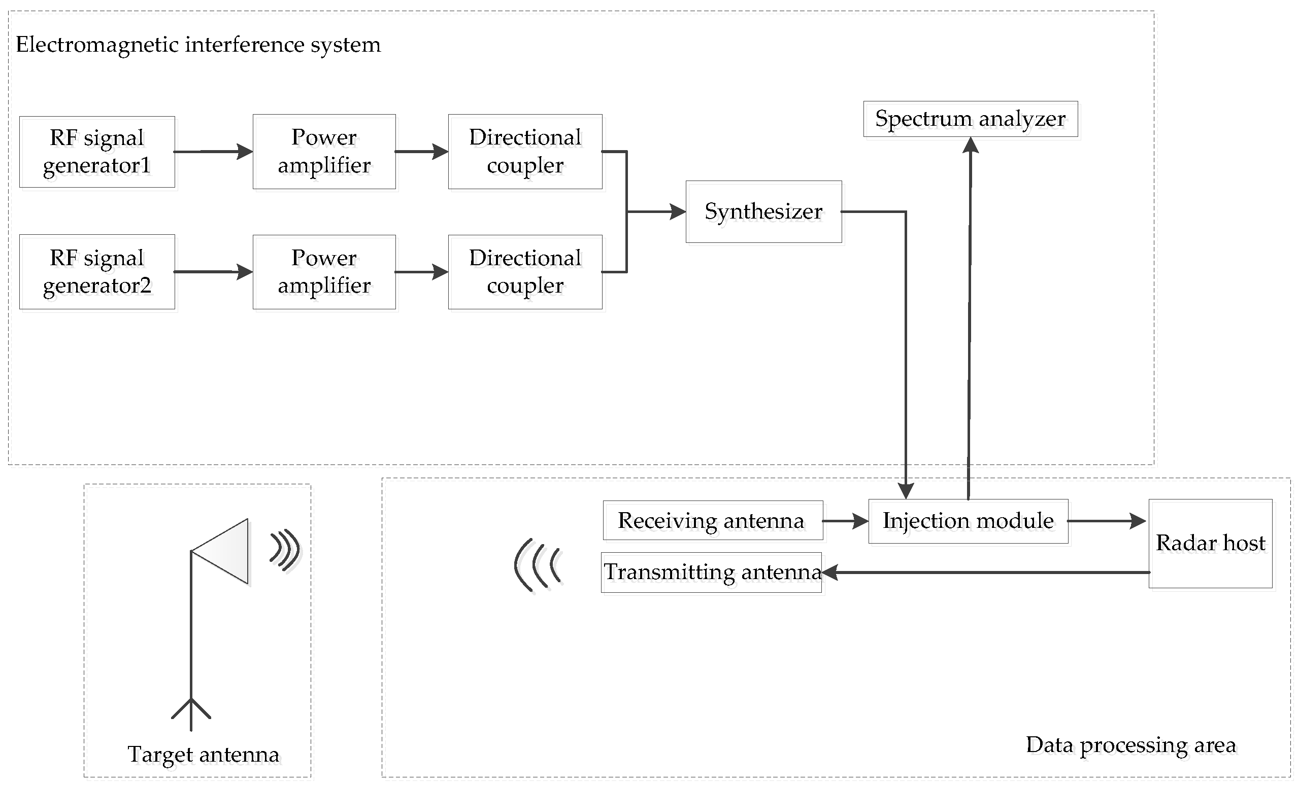
Figure 1. The flow chart of the test system.
Electronics 11 03722 g001
Figure 2. The IMFA-3 signal imaging (Δf1 = −0.18 GHz and Δf2 = −0.36 GHz).
Electronics 11 03722 g002
Figure 3. Variation of the IMFA−3 level changing with single interference component.
Electronics 11 03722 g003
Figure 4. Variation of the four groups of the IMFA−3 levels with the interference field strength.
Electronics 11 03722 g004
Figure 5. Variation curve of the IMFA−5 with the interference field strength.
Electronics 11 03722 g005
Table 1. System output signal amplitude (i = 5).
Polynomial FrequencyMagnitudePolynomial FrequencyMagnitude
a00y0a4x4f1f2 3 2 a 4 U 1 U 2 ( U 1 2 + U 2 2 )
a1x1f1 a 1 U 1 2f1 − 2f2 3 4 a 4 U 1 2 U 2 2
f2 a 1 U 2 a5x52f1f2 a 5 U 1 U 2 ( 5 4 U 1 3 + 3 8 U 1 U 2 2 )
a2x2f1f2 1 2 a 2 U 1 U 2 2f2f1 a 5 U 1 U 2 ( 5 4 U 2 3 + 3 8 U 2 U 1 2 )
a3x32f1f2 3 4 a 3 U 1 2 U 2 3f1 − 2f2 11 16 a 5 U 1 3 U 2 2
2f2f1 3 4 a 3 U 1 2 U 2 3f2 − 2f1 11 16 a 5 U 2 3 U 1 2
Table 2. Two groups of the IMFA-3 test results (E1 = 20 dBV/m, E2 = 24.5 dBV/m).
Serial NumberΔf1/GHzΔf2/GHzΔf1/GHzΔf2/GHz
−0.18−0.36−0.36−0.72
RIM3/mUIM3/(dBmV)RIM3/mU IM3/(dBmV)
1647.28.11531.011.2
21243.07.7977.211.4
3720.77.9636.711.5
4380.97.21169.011.2
51113.07.01214.011.2
61575.07.81619.011.6
7249.77.71316.011.6
81570.07.2259.411.3
9975.76.4548.910.7
101444.07.31444.011.3
Average/7.4/11.3
Table 3. Test data of the IMFA−5 signal with the interference field strength.
E1E2RIM5/mUIM5/dBmVE1E2RIM5/mUIM5/dBmV
1231360.0−2.01202942−4.5
9462.71.29590.9−1.3
61141.02.76751.40.5
3733.40.33894.7−2.0
0378.7−3.003598.0−5.2
−3464.2−6.3−3//
−63655.0−9.0−6//
E1E2RIM5/mUIM5/dBmVE1E2RIM5/mUIM5/dBmV
12−31320.0−7.7−312//
9319.4−3.79//
61326.0−1.961495.0−4.5
3773.2−5.533244.0−7.4
E1E2RIM5/mUIM5/dBmVE1E2Rm5/mUIM5/dBmV
002648.0−7.03−63118.0−8.2
031490.0−3.73−3948.7−6.5
061214.0−2.630832.4−3.4
33//331231.00.0
36//361455.01.4
39//391447.0−0.1
Note: E1 and E2 respective interference field strengths of the dual frequency, respectively. The unit is dBV/m.
Table 4. Test results of theIMFA−5 with the same proportional change of interference field strength.
E1/E2(dB)E1/(dBV/m)E2/(dBV/m)RIM5/mUIM5/dBmV
31187532.9
96689.23
63583.42
30620.9−3
612610361.3
93900.71.4
60848.9−0.1
3−33465−6.5
91231320−1.6
901148−1.7
6−3702.7−3.4
3−63076−9.7
Publisher’s Note: MDPI stays neutral with regard to jurisdictional claims in published maps and institutional affiliations.