Article

Design of a Dual-Polarization Dipole Antenna for a Cylindrical Phased Array in Ku-Band

1
EMC and Microwave System Laboratory, Beijing Institute of Technology, Beijing 100081, China
2
School of Integrated Circuits and Electronics, Beijing Institute of Technology, Beijing 100081, China
3
National Key Laboratory of Science and Technology on Test Physics and Numerical Mathematics, Beijing 100076, China
*
Author to whom correspondence should be addressed.
Electronics 2022, 11(22), 3796; https://doi.org/10.3390/electronics11223796
Submission received: 20 October 2022 / Revised: 12 November 2022 / Accepted: 14 November 2022 / Published: 18 November 2022
(This article belongs to the Topic Antennas)

Abstract

:
This paper proposes a dual-polarization dipole antenna for a cylindrical phased array working in Ku-band. The dipole antenna is double-layer structured and is composed of two orthogonal butterfly shaped dipole radiators, two ground co-planar waveguide (GCPW) feeding structures and vias. Each dipole is in the shape of a butterfly. The dipole patch is grooved triangularly and one side of it is bent into an N shape, which effectively expands the working frequency band of the antenna. The double-layer structure improves the isolation between the antenna ports. The antenna works between 15 GHz to 16.2 GHz and the isolation between the antenna’s two feeding ports in this band is better than 20 dB. The proposed dipole antenna is applied in a 32-element cylinder array. The simulation and measured results show that the array can scan between −60° to +60° in the azimuth plane with a gain fluctuation less than 2.5 dB. Therefore, the proposed design is an attractive candidate for conformal devices at Ku-band frequencies, and it also has a great potential for application in larger antenna arrays.

1. Introduction

Compared with traditional planar arrays, conformal arrays have unparalleled advantages in reducing aerodynamic drag, wide-angle coverage and low radar cross section (RCS) on aircraft and missiles [1]. Therefore, the conformal phased array antenna has great potential in radar system.
Dual-polarization antennas radiate and receive electromagnetic waves with the same frequency and orthogonal polarizations, and are widely applied to different fields. In wireless communications, the application of dual-polarized antennas can enlarge channel capacity and enhance spectral efficiency [2,3]. When used in wireless energy transmission systems, they can enhance the efficiency of energy transfer [4]. Particularly, it is an efficient approach for radar systems to solve the anti-jamming and multipath immunity problems. In radar detecting, they can further obtain other information except amplitude and phase from the scattered wave of the target and lead to a higher detecting level [5,6,7,8].
In recent years, many researchers focus on the study of conformal arrays and dual-polarization antennas. P. Wang et al. [9] introduce a broadband conformal antenna array installed on a large metal cylinder. By using several Vivaldi antenna elements, the antenna array achieves ultra-wideband and low cross polarization level. However, the antennas cannot fit the cylinder completely, and reduce the aerodynamic performance of the carrier. Microstrip antenna has always been one of the main candidates for conformal arrays for its good conformal ability, though it often suffers from the problem of narrow bandwidth. Ref. [10] proposes a cylindrical conformal array with microstrip antenna elements. It introduces the defective ground structures (DGS) to solve the problem of narrow bandwidth caused by the deformation of the array antenna when conformal to the cylindrical surface. In [11], a full solid angle scanning cylindrical-and-conical conformal phased array antenna is proposed. As a part of it, a cylindrical array with microstrip antennas as the elements is designed. It shows a good scanning performance, but the bandwidth is only 1.74%. In [12], the differential feeding technique is applied to dual-polarized microstrip antenna to achieve a good cross polarization level. Based on a dual-polarized patch antenna element with vertical orthogonal baluns, a non-planar conformal dual-polarized phased array antenna is proposed in [13,14]. The antenna has a port isolation of better than 40 dB, but its profile is relatively high. Due to the virtues of low profile, various forms, easy processing etc., printed dipoles are also widely used in conformal antennas. In [15,16,17], tightly coupled dipole are applied to realize dual-polarization cylindrical conformal arrays. Ultra-wide bandwidth and large scanning range can be achieved. Ref. [18] introduces a novel conformal dipole antenna with polarization diversity. The polarization diversity is achieved by placing two dipole antennas orthogonally on the outside of a capsule shell. In [19], two curved patch dipoles are arranged orthogonally in the cross contour of a hemispherical shell to realize a circularly polarized antenna for the ground terminal facilities of the global satellite navigation system. Based on the polyimide film, J. J. Peng et al. [20] propose a dipole conformal array working in P-band for the UAV radar. Y. Gao et al. [21] propose a dual-polarized monopulse conical conformal antenna with Yagi antennas as the radiation structures. The antenna achieves wide bandwidth by taking double diamond dipoles as excited elements [22]. In [23], a crossed dipole antenna element is employed to a cylindrical phased array for weather surveillance radars. A port isolation over 50 dB is achieved at the cost of antenna profile.
As stated above, it is difficult for conformal dual polarized phased arrays to simultaneously have wide bandwidth, high isolation, low profile and large scanning angle. In this article, a dual-polarization dipole antenna, which is used to a cylindrical phased array antenna in Ku-band, is proposed. The antenna consists of dual pairs of dipoles placed orthogonally. Different from the conventional printed dipole antenna, this paper proposes a dipole with the shape of a butterfly wing. With the dipole shape modification, the impedance bandwidth and the port isolation of the antenna is greatly improved. Taking it as the antenna element, a linear conformal phased array which has 32 elements is designed, fabricated, and measured. The measured results show that the proposed dual-polarization conformal phased array antenna can realize beam scanning in the range of −60° to 60° with the gain fluctuation less than 2.42 dB.

2. Design of the Dipole Antenna

As a simple planar antenna, the printed dipole antenna is not only simple in forms but also has many variants to improve its performance. It is a promising antenna candidate for conformal antennas. In this paper, a dual polarization printed dipole is designed, which has the characteristics of certain frequency band, high isolation, simple structure, and low profile.
The model of the proposed antenna is shown in Figure 1. It is composed of metal radiators, two dielectric substrates, isolation ground, vias, and grounded coplanar waveguide (GCPW) feed structures. The butterfly shaped dipole is printed on the top surface of the upper substrate. The GCPW feeding structure is printed on bottom surface of the lower substrate. The isolation ground is between the two substrates, which improves the port isolation by reducing the effect of the CPW slot to the antenna’s radiation. The substrates are both F4B, which has better flexibility and makes the antenna array easy to install on the cylindrical surface. The dielectric constant is 2.2 and the loss tangent is 0.007. The thicknesses of the upper and lower substrates are both 1 mm.
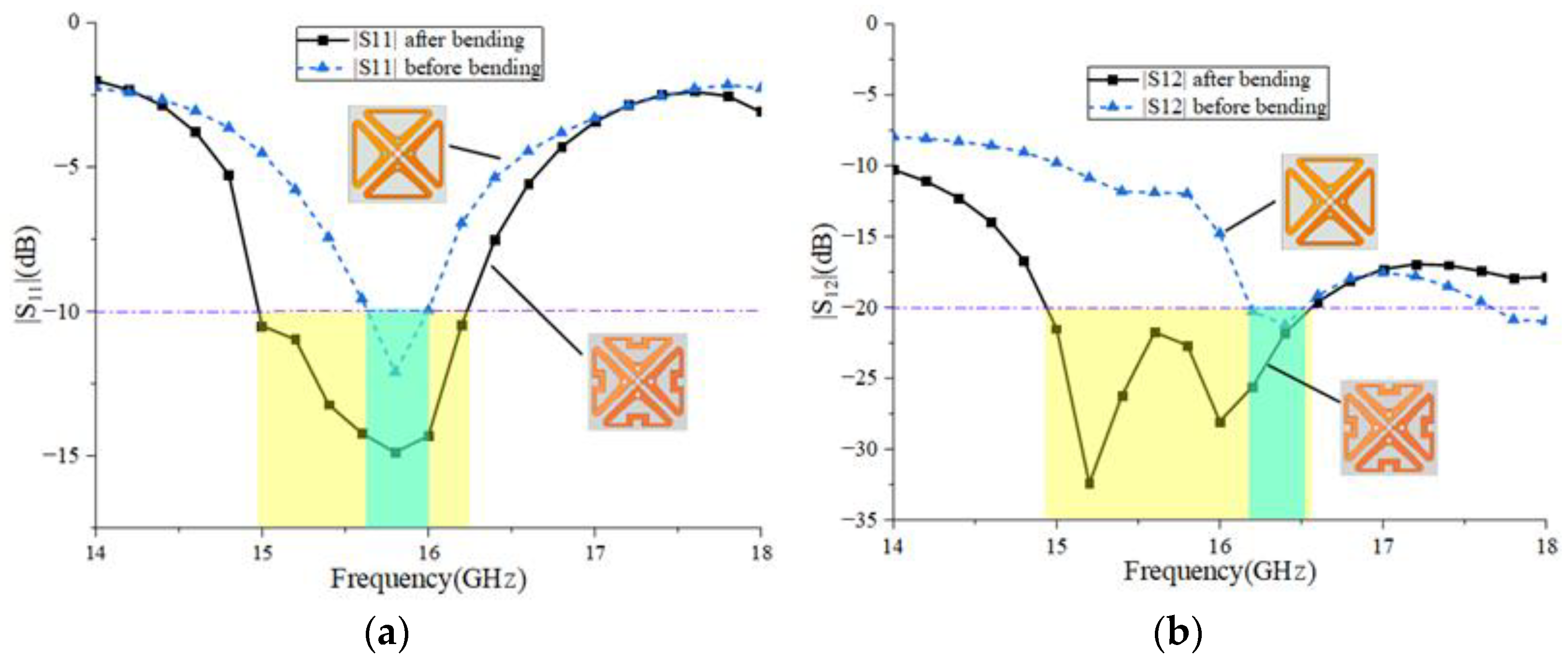
The radiator consists of two pairs of rotationally symmetrical dipoles. The length of one dipole arm is 0.2 λ 0 (L = 3.8 mm), and the length of a pair of dipoles is 0.437 λ 0 , where λ 0 is the free space wavelength at the center frequency. The dipoles are designed in the shape of a butterfly by grooving the redating patch and bending the side into an N shape. Through the bending structure, an additional capacitance is introduced, and the antenna bandwidth is widened. The antenna is simulated with Ansys HFSS 2019. Figure 2 shows the impedance performance and the port isolation of two equal sized antennas with and without bending. Because the two pair of dipoles are rotationally symmetrical, only |S11| is shown in the figure. Figure 2a shows that the frequency band of |S11| less than −10 dB is 15.6–16.0 GHz before side bending, while after side bending it becomes 15.0–16.2 GHz. An improvement of the relative bandwidth from 1.9% to 8% is achieved with the addition of the bending structure. Figure 2b shows the port isolation of the antennas. It can be observed that the isolation is better than 20 dB only in the frequency range of 16.2–16.5 GHz before side bending. After side bending, the bandwidth of 20 dB isolation increases to 14.9–16.56 GHz, with the −10 dB impedance bandwidth contained.
Since the distance between the two dipole feeding points is only 1.7 mm, directly connecting the SMP connectors with the feeding points will lead to the contradiction. Therefore, a grounded coplanar waveguide (GCPW) structure is introduced. It combines the advantages of microstrip line and coplanar waveguide structure [24,25]. The GCPW structure not only solves the problem of feeding contradiction, but also leads to a better impedance match. Four vias are drilled through the substrates, with two for grounding, and the others as part of the feed to connect the dipole with the GCPW.
The detailed antenna structure and parameters are shown in Figure 3. The parameters are analyzed and optimized to obtain good antenna performance. The optimal parameters of the proposed antenna are listed in Table 1.
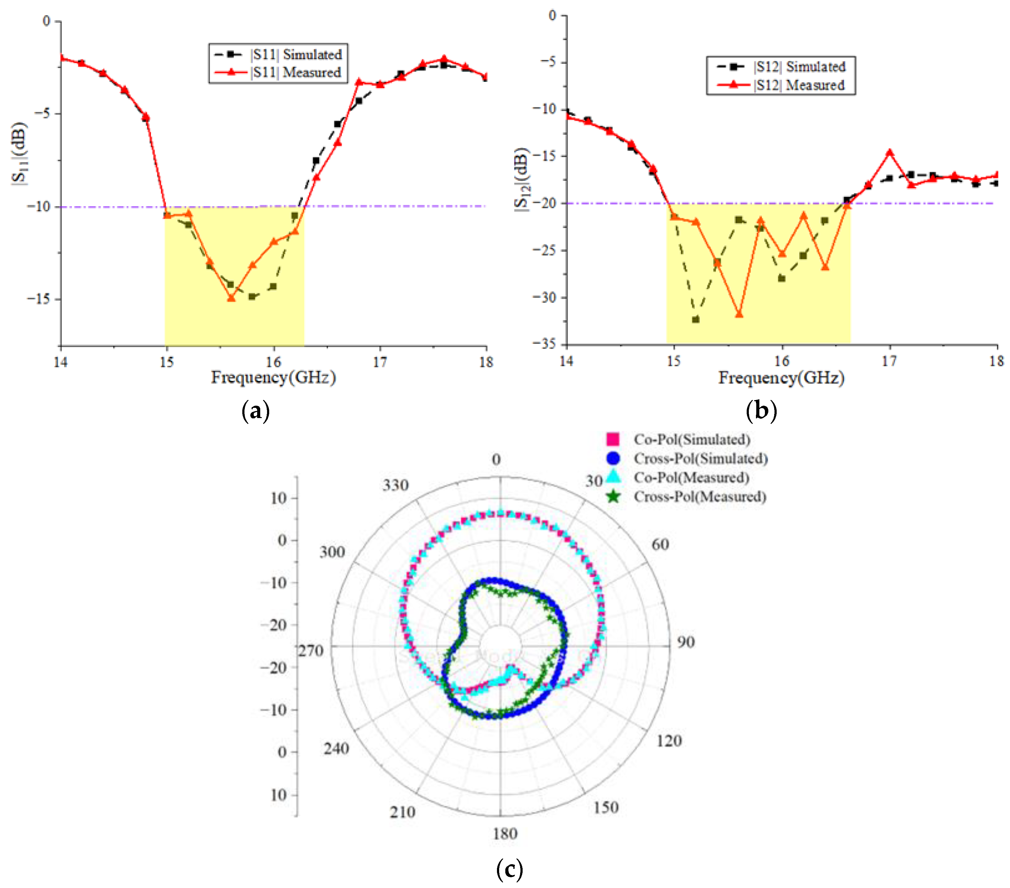
Figure 4 shows the simulated and measured results of |S11|, |S12| and radiation patterns of the proposed dipole antenna. It can be observed that the measured results agree well with the simulated results. The measured bandwidth of |S11| and |S12|is just as the simulated ones described above. Figure 4c shows the co-polarization and cross-polarization patterns of the antenna when one port is fed. Because of the rotational symmetry, the patterns are the same when the other port is fed. As can be seen from the figure, the antenna has a gain of about 6.2 dBi, and the cross-polarization level is lower than −16.5 dB.
The surface current distributions of the antenna at 15.6 GHz are shown in Figure 5. It can be seen that the synthesizing surface current on the dipole is mainly along the y-axis when Port 1 is excited, while along the x-axis with Port 2 fed. Therefore, two orthogonal polarizations are achieved with a relatively good purity of polarization.

3. Design of the Cylindrical Array

With the proposed dipole antenna, a dual-polarization cylindrical phased array antenna is designed for Ku-band radar applications. The geometry and prototype of the antenna array is depicted in Figure 6. By comprehensive consideration of the size of the cylindrical surface and the grating lobe suppression of the antenna array, the element spacing is set to be 9 mm (approximately 0.47 λ 0 ). The array is conformal to a cylindrical aluminum surface The radius of the cylindrical surface is 185 mm, the height is 30 mm, the overall center angle of the metal cylindrical surface is 96°, and the array spanning angle is 88°. A distance of 1 mm is reserved between the antenna and the cylindrical surface to reduce the influence of the metal surface on the feed. There are holes in the metal cylindrical surface through which the SMP connectors are connected to the antennas.
The antenna elements conformal to the cylindrical surface are excited with equal amplitude and proper phase to direct the array beam. The feeding phase of the ith element is
p h a s e i = 2 π λ x i sin θ 0 cos φ 0 + y i sin θ 0 sin φ 0 + z i cos θ 0
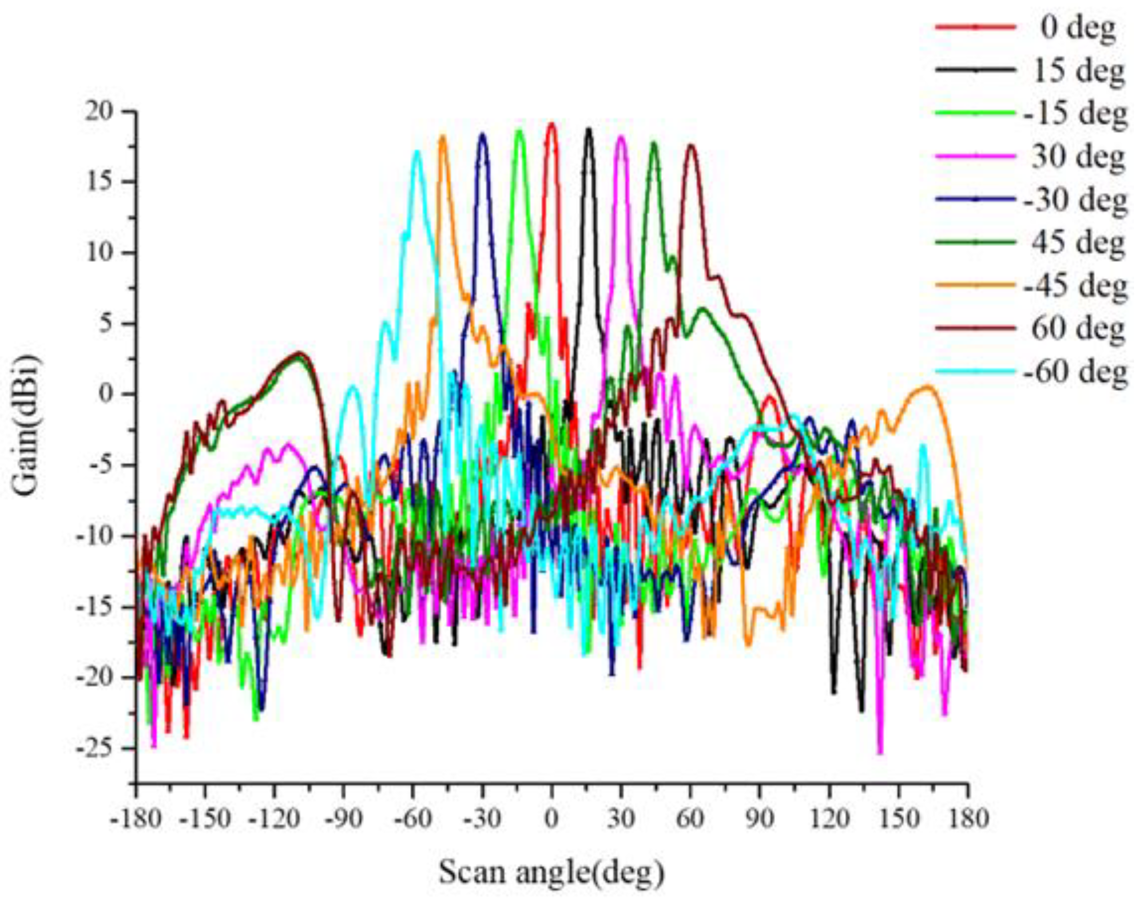
where θ 0 , φ 0 is the scanning angle, and x i , y i , z i represents the coordinate of the i th element. With the coordinate system shown in Figure 6, the scanning angles in the azimuth plane have θ 0 of 90 . Figure 7 shows the simulation patterns for different scanning angles at the center frequency 15.6 GHz. Since the scanning performances of the array for horizontal polarization and vertical polarization are similar, only the patterns for the horizontal polarization are given.
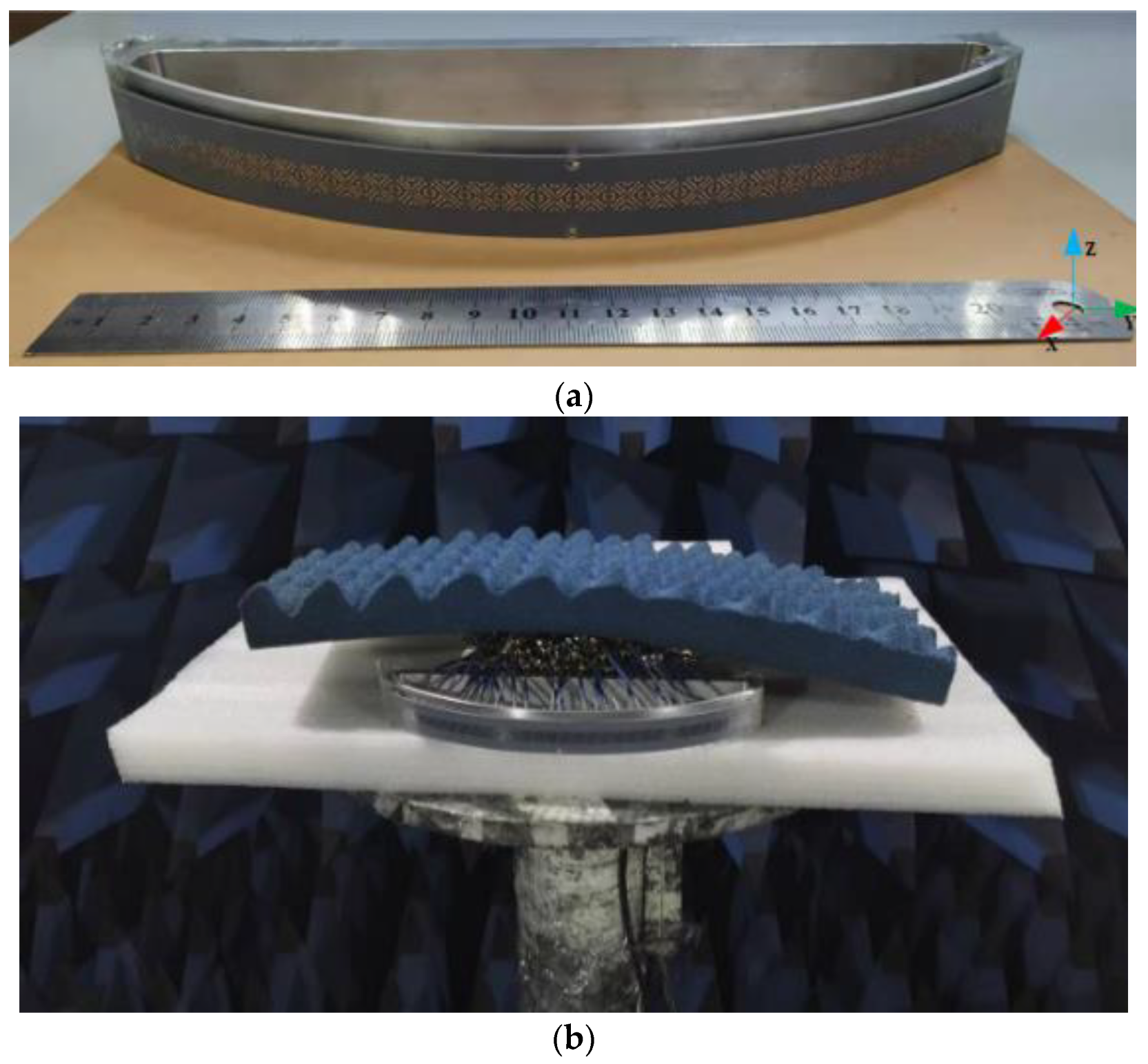
It can be seen from the simulation results that when the scanning angle is 0°, the maximum gain is 19.06 dBi, and when the scanning angle is −60°, the gain is17.05 dBi. The gain fluctuation is approximately 2 dB in the scanning range of −60° to +60°. In order to verify the simulation results of the proposed cylindrical array, it is fabricated and measured in a microwave anechoic chamber. The array photograph and the measurement scene are as shown in Figure 8. The size of the microwave anechoic chamber is 6.4 m × 5 m × 3.2 m. Its equipment includes a 2 m × 2 m scanning shelf, a rotating platform, a vector network analyzer, and a control cabinet. Making use of a standard Ku-band horn as the receiving antenna, the radiation pattern of the array is measured by far-field measurement.
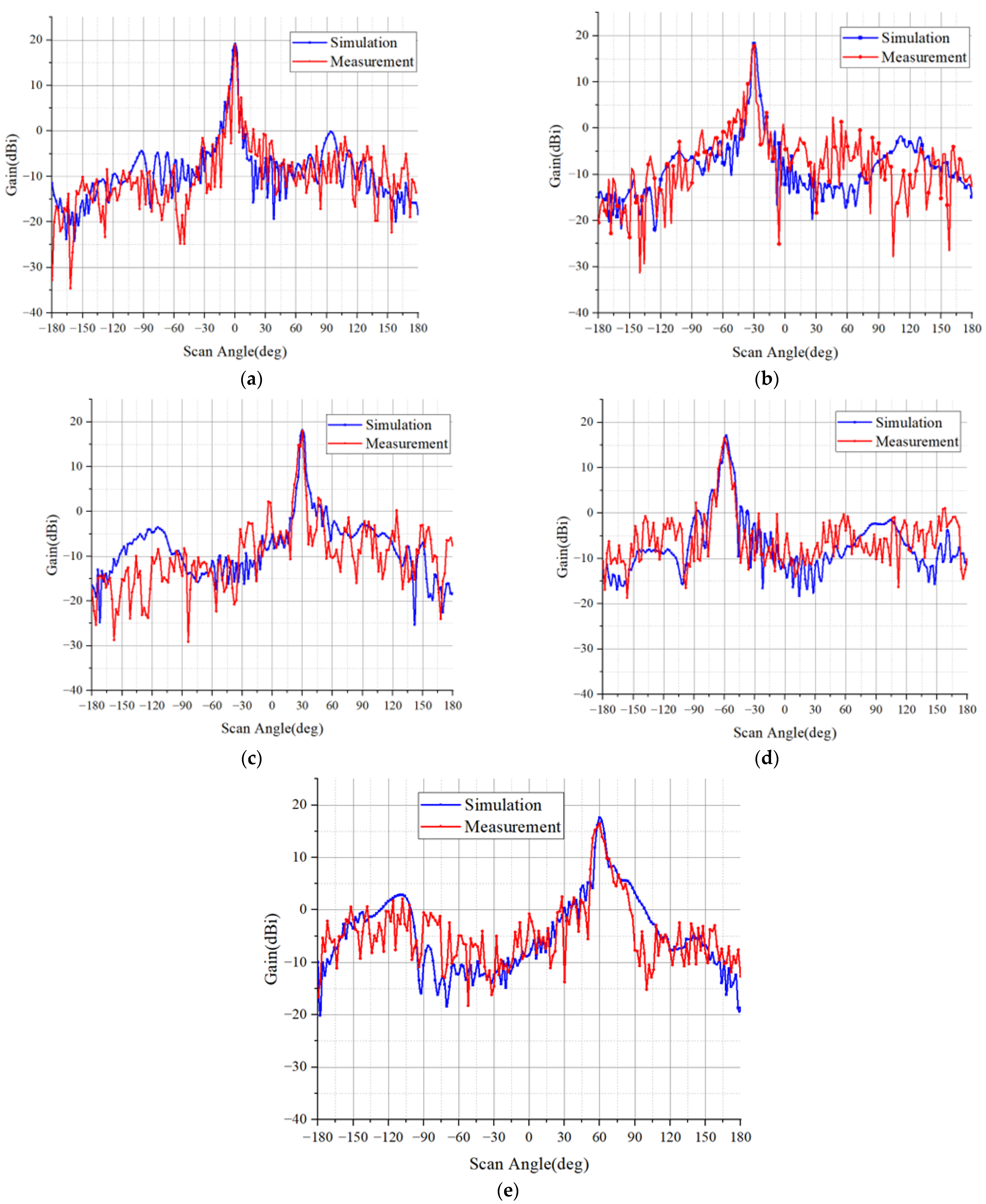
Figure 9 shows the simulated and measured results of 0°, ±30°, ±60° for the horizontal-polarization patterns. It can be seen that the measured results are in good agreement with the simulated ones. Table 2 lists the gains at these scan angles. It is observed that the measured gains are slightly lower than the simulation ones. This is caused by the losses of the connectors and cables. At broadside, all the 32 elements contribute to the main lobe and the gain is the maximum. When the beam is scanned, some of the elements on the opposite side of the scanning angle have less contribution to the main lobe, resulting in the decreasing gains. However, the scan loss is only 2.42 dB from 0° to +60°, which shows the excellent wide-angle scanning performance for a cylindrical conformal array.
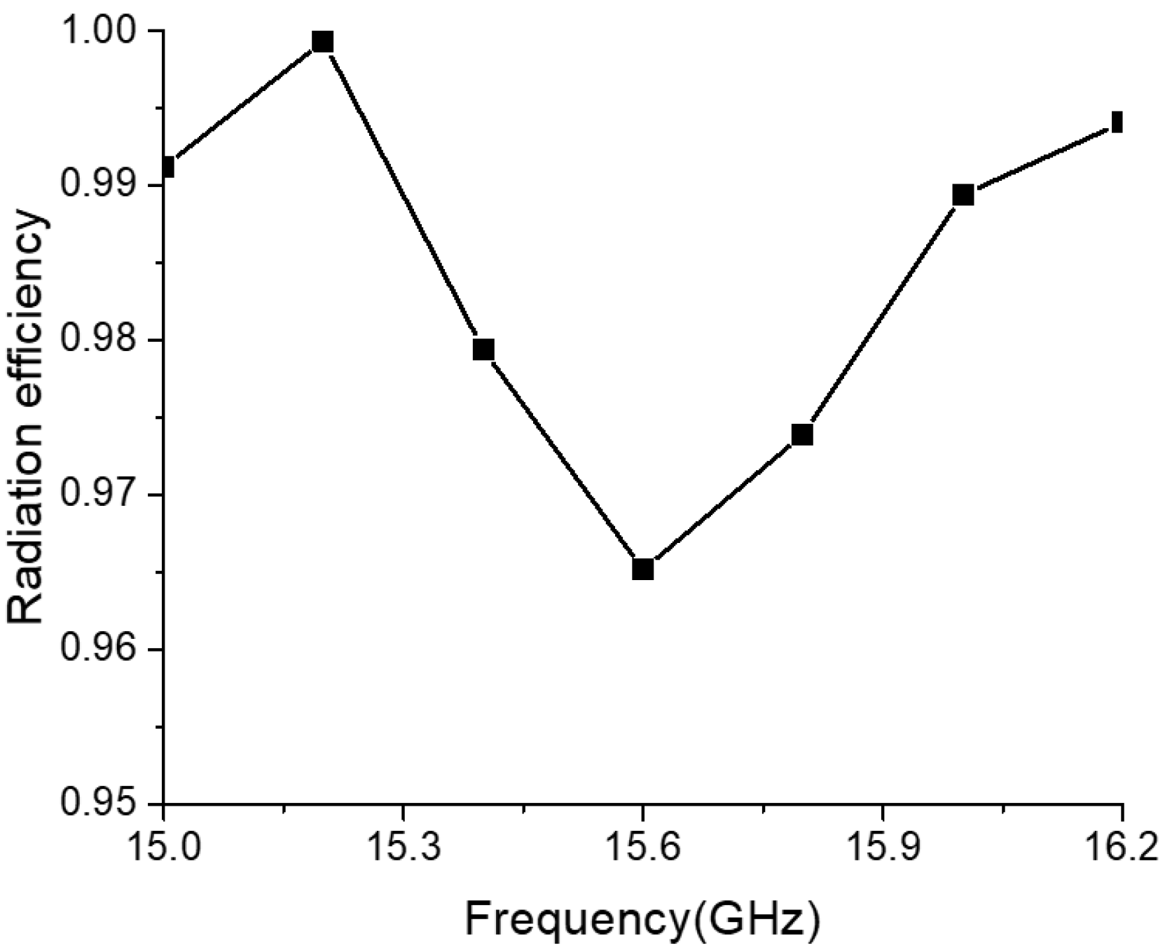
Figure 10 shows the simulated radiation efficiency of the array at broadside. As can be seen, the array has a radiation efficiency better than 96% in the working frequency band.
A comparison between this study and other cylindrical arrays in existing literatures is carried out in Table 3. The proposed dual polarization conformal array has the widest scan angle with small scan loss and almost the lowest profile. The bandwidth and port isolation are medium, which is sufficient for many applications.

4. Conclusions

This article proposes a dual-polarization dipole antenna in Ku-band. By grooving the patch and bending the dipole side, the antenna bandwidth is effectively widened, and the port isolation is greatly improved. Additionally, the proposed double-layered design, which introduces an isolation ground between two substrates also plays an important role in the port isolation improvement. The designed dipole antenna is applied to a cylindrical phased array, which realize a scan range of −60° to 60° with the gain fluctuation less than 2.42 dB. The measured results verify the simulation results, which provides a guidance for the design of large-scale arrays and dual polarization arrays.
This study only discusses the performance of a one-dimensional linear array. An array on a two-dimensional surface will be further studied in the future.

Author Contributions

Conceptualization, N.Z. and Z.X.; methodology, N.Z. and L.G.; software, N.Z., P.Z. and L.G.; validation, N.Z. and P.Z.; formal analysis, N.Z. and P.Z.; investigation, L.G.; resources, J.Q.L.; data curation, N.Z. and J.Q.L.; writing—original draft preparation, N.Z.; writing—review and editing, N.Z. and Z.X.; visualization, P.Z. and L.G.; supervision, J.Q.L.; project administration, J.Q.L.; funding acquisition, Z.X. All authors have read and agreed to the published version of the manuscript.

Funding

This research received no external funding.

Data Availability Statement

The raw/processed data required to reproduce these findings cannot be shared at this time as the data also forms part of an ongoing study.

Conflicts of Interest

The authors declare no conflict of interest.

References

  1. Mailloux, R.J. Phased Array Antenna Handbook; Artech House: Boston, MA, USA, 2005; p. 185. [Google Scholar]
  2. Li, H.; Kang, L.; Wei, F.; Cai, Y.M.; Yin, Y.Z. A Low-Profile Dual-Polarized Microstrip Antenna Array for Dual-Mode OAM Applications. IEEE Antennas Wirel. Propag. Lett. 2017, 16, 3022–3025. [Google Scholar] [CrossRef]
  3. Yang, B.; Huang, H.; Feng, B.; Deng, L. A Dual-Polarized Zhe-Shaped Conformal Patch Antenna for 5G Millimeter-Wave Applications. In Proceedings of the IEEE 4th International Conference on Electronic Information and Communication Technology (ICEICT), Xi’an, China, 18–20 August 2021; pp. 866–868. [Google Scholar]
  4. Liao, L.; Li, Z.; Tang, Y.; Chen, X. Dual-Polarized Dipole Antenna for Wireless Data and Microwave Power Transfer. Electronics 2022, 11, 778. [Google Scholar] [CrossRef]
  5. Benny, S.; Sahoo, S. Analysis of Optimized Subarray Configuration for Cross Polarization Reduction for Phased Array Antennas used in Weather Radar. In Proceedings of the IEEE International Symposium on Antennas and Propagation and USNC-URSI Radio Science Meeting (APS/URSI), Singapore, 4–10 December 2021; pp. 519–520. [Google Scholar]
  6. Wang, X.; Zhou, S.; Liu, H.; Yan, J.; Su, H.; Li, H.; Yin, K.; Sun, W.; Zhou, L. Polarization Parameter Estimation of Conformal MIMO Radar Targets. In Proceedings of the IEEE Radar Conference (RadarConf20), Florence, Italy, 21–25 September 2020; pp. 1–5. [Google Scholar]
  7. Huai, W.; Yanyan, Z.; Xinghui, P.; Xinying, B. An S/C Dual-Band Dual-Polarization Array for Synthetic Aperture Radar. In Proceedings of the IEEE 9th International Symposium on Microwave, Antenna, Propagation and EMC Technologies for Wireless Communications (MAPE), Chengdu, China, 26–29 August 2022; pp. 184–187. [Google Scholar]
  8. Kobayashi, T.; Ko, K.; Choi, S.J.; Choi, J.H. Orthogonal Dual Polarization GPR Measurement for Detection of Buried Vertical Fault. IEEE Geosci. Remote Sens. Lett. 2022, 19, 1–5. [Google Scholar] [CrossRef]
  9. Wang, P.; Wen, G.; Zhang, H.; Sun, Y. A Wideband Conformal End-Fire Antenna Array Mounted on a Large Conducting Cylinder. IEEE Trans. Antennas Propag. 2013, 61, 4857–4861. [Google Scholar] [CrossRef]
  10. Liu, Y.; Wang, T.; Zhong, P.; Wang, S. Cylindrical conformal broadband array antenna based on defective ground structure. In Proceedings of the IEEE 4th Advanced Information Technology, Electronic and Automation Control Conference (IAEAC), Chengdu, China, 20–22 December 2019; pp. 382–385. [Google Scholar]
  11. Xia, Y.; Muneer, B.; Zhu, Q. Design of a Full Solid Angle Scanning Cylindrical-and-Conical Phased Array Antennas. IEEE Trans. Antennas Propag. 2017, 65, 4645–4655. [Google Scholar] [CrossRef]
  12. Zhang, J.; Chai, S.; Xiao, K.; Ding, L.; Zhao, F. Differential feeding technique for full-polarization conformal phased array. In Proceedings of the International Workshop on Electromagnetics: Applications and Student Innovation Competition, London, UK, 30 May–1 June 2017; pp. 87–88. [Google Scholar]
  13. Lang, L.; Mei, L.; Zhang, N. Design and Simulation of Dual-polarized Non-planar Conformal Phased Array Antenna. In Proceedings of the Photonics & Electromagnetics Research Symposium—Fall (PIERS—Fall), Xiamen, China, 17–20 December 2019; pp. 2385–2392. [Google Scholar]
  14. Li, J.; Yang, S.; Gou, Y.; Hu, J.; Nie, Z. Wideband dual-polarized magnetically coupled patch antenna array with high port isolation. IEEE Trans. Antennas Propag. 2016, 64, 117–125. [Google Scholar] [CrossRef]
  15. Xiao, S.; Yang, S.; Zhang, H.; Xiao, Q.; Chen, Y.; Qu, S.-W. Practical Implementation of Wideband and Wide-Scanning Cylindrically Conformal Phased Array. IEEE Trans. Antennas Propag. 2019, 67, 5729–5733. [Google Scholar] [CrossRef]
  16. Long, X.-P.; Zhou, S.-Z.; Zong, Z.-Y.; Wu, W. Design of Broadband Dual-Polarized Conformal Phased Antenna. In Proceedings of the IEEE International Symposium on Antennas and Propagation and USNC-URSI Radio Science Meeting (APS/URSI), Singapore, 4–10 December 2021; pp. 989–990. [Google Scholar]
  17. Xiao, Q.; Yang, S.; Bao, H.; Chen, Y.; Qu, S. A wideband dual-polarized conformal phased array based on tightly coupled dipoles. In Proceedings of the Sixth Asia-Pacific Conference on Antennas and Propagation (APCAP), Xi’an, China, 16–19 October 2017; pp. 1–3. [Google Scholar]
  18. Wang, Y.; Yan, S. Novel Conformal Dipole Antenna with Polarization Diversity for Biomedical Applications. In Proceedings of the International Conference on Microwave and Millimeter Wave Technology (ICMMT), Shanghai, China, 20–23 September 2020; pp. 1–3. [Google Scholar]
  19. Yan, Y.-D.; Jiao, Y.-C.; Zhang, C.; Zhang, Y.-X.; Chen, G.-T. Hemispheric Conformal Wide Beamwidth Circularly Polarized Antenna Based on Two Pairs of Curved Orthogonal Dipoles in Space. IEEE Trans. Antennas Propag. 2021, 69, 7900–7905. [Google Scholar] [CrossRef]
  20. Peng, J.-J.; Qu, S.-W.; Xia, M.; Yang, S. Wide-Scanning Conformal Phased Array Antenna for UAV Radar Based on Polyimide Film. IEEE Antennas Wirel. Propag. Lett. 2020, 19, 1581–1585. [Google Scholar] [CrossRef]
  21. Gao, Y.; Jiang, W.; Hu, W.; Wang, Q.; Zhang, W.; Gong, S. A Dual-Polarized 2-D Monopulse Antenna Array for Conical Conformal Applications. IEEE Trans. Antennas Propag. 2021, 69, 5479–5488. [Google Scholar] [CrossRef]
  22. Gao, Y.; Jiang, W.; Hong, T.; Gong, S. A High-gain Conical Conformal Antenna with Circularly Polarization and Axial Radiation in X-band. In Proceedings of the 13th European Conference on Antennas and Propagation (EuCAP), Krakow, Poland, 31 March–5 April 2019; pp. 1–4. [Google Scholar]
  23. Golbon-Haghighi, M.-H.; Mirmozafari, M.; Saeidi-Manesh, H.; Zhang, G. Design of a Cylindrical Crossed Dipole Phased Array Antenna for Weather Surveillance Radars. IEEE Open J. Antennas Propag. 2021, 2, 402–411. [Google Scholar] [CrossRef]
  24. Hu, J.; Sligar, A.; Chang, C.H.; Lu, S.L.; Settaluri, R.K. A grounded coplanar waveguide technique for microwave measurement of complex permittivity and permeability. IEEE Trans. Magn. 2006, 42, 1929–1931. [Google Scholar]
  25. Chen, J.S. A CPWG-fed dual-frequency rectangular patch antenna. Microw. Opt. Technol. Lett. 2002, 34, 397–398. [Google Scholar] [CrossRef]
Figure 1. Dipole Antenna model.
Electronics 11 03796 g001
Figure 2. Effect of side bending on antenna bandwidth. (a) |S11| and (b) |S12|.
Electronics 11 03796 g002
Figure 3. Detailed antenna structure: (a) side view; (b) top view; (c) isolation ground; and (d) bottom view.
Electronics 11 03796 g003
Figure 4. Simulation and measurement results of the dipole antenna: (a) |S11|; (b) |S12|; and (c) co/cross-pol radiation patterns.
Electronics 11 03796 g004
Figure 5. Current distributions of the proposed antenna fed by (a) Port 1 and (b) Port 2.
Electronics 11 03796 g005
Figure 6. Array antenna model of (a) overall view (b) top view.
Electronics 11 03796 g006
Figure 7. Simulation results of the array in the azimuthal plane.
Electronics 11 03796 g007
Figure 8. The prototype of the phased array. (a) Array photograph (b) the measurement scene.
Electronics 11 03796 g008
Figure 9. Simulated and measured results for different scan angles. (a) φ = 0°. (b) φ = −30°. (c) φ = 30°. (d) φ = −60°. (e) φ = 60°.
Electronics 11 03796 g009
Figure 10. Simulated radiation efficiency of the array at broadside.
Electronics 11 03796 g010
Table 1. Dimensions for the Proposed Antenna (unit: mm).
ParameterSizeParameterSize
L3.8Rs1.9
L16.25Lf12.54
L32Lf20.84
L40.8Lf31.39
L53Wf1.1
Ls3Wf10.4
W13Ws1.21
W22H1
Lf0.75
Table 2. Gain of the array at different scan angles.
−60°−30°30°60°
Simulation (dBi)17.3218.2919.0618.1217.56
Measurement (dBi)16.6617.8318.9017.9616.48
Table 3. Comparison of cylindrical arrays.
ReferenceBandwidthPort IsolationThicknessScan AngleScan LossGain
(Broadside)
[11]1.74%Sigle-polarized0.052l0−30°~+30°1.25 dB20.8 dBi
[13]20.98%>45 dB0.21l0−45°~+45°1.88 dB14.92 dBi
[15]100%>17 dB0.28l0−60°~+60°2.5 dBNot mentioned
[23]7.14%>50 dB1.05l0Switching beam-Not mentioned
This work8.0%>21 dB0.11l0−60°~+60°2.42 dB19.06 dBi
Publisher’s Note: MDPI stays neutral with regard to jurisdictional claims in published maps and institutional affiliations.