Article

Detent Force Reduction in Linear Interior Permanent Magnet Generator for Direct-Drive Wave Power Conversion

1
School of Electric Power Engineering, Nanjing Institute of Technology, Nanjing 211167, China
2
Department of Energy Technology, Aalborg University, 9220 Aalborg, Denmark
3
College of Electrical Engineering, Zhejiang University, Hangzhou 310027, China
*
Author to whom correspondence should be addressed.
Electronics 2022, 11(23), 3896; https://doi.org/10.3390/electronics11233896
Submission received: 14 October 2022 / Revised: 17 November 2022 / Accepted: 19 November 2022 / Published: 25 November 2022

Abstract

:
The permanent magnet linear generator is widely applied in the direct-drive wave energy converter (DD-WEC) because of its high power density. In this paper, a novel tubular permanent magnet linear generator, which consists of multilayer and interior permanent magnets (MI-TLPMGs), is presented for DD-WEC, which improves the output power and back electromotive force (back EMF) through the flux concentrating effect. However, MI-TLPMGs with multilayer embedded permanent magnets have severe problems regarding force ripples and detent force, which affect the DD-WEC’s dynamics. Therefore, a DD-WEC system with MI-TLPMGs is proposed, and the effect of the detent force on the dynamic performance of the DD-WEC is analyzed theoretically. Then, the L-type auxiliary teeth and magnetic barriers, which are optimized by the Taguchi method, are introduced to minimize the detent force of the MI-TLPMGs. After optimization using the Taguchi method, the amplitude of the detent force is reduced from the initial 21.7 N to 5.2 N, which means it has weakened by nearly 76.1%. Finally, a prototype has been manufactured and measured in the wave tank to verify the optimization results.

1. Introduction

The rapidly decreasing reserves and the negative environmental impacts of traditional energy sources have become an obstacle to the sustainable development of countries [1]. Therefore, the energy crises and global warming have forced humans to move forward to renewable energy sources [2]. Considering the fact that 70% of the earth’s surface is covered by oceans, wave energy has attracted increasing attention from scholars due to its higher energy density and global availability. Compared to the other sources of renewable energy, wave power is supposed to be the ideal and most promising energy resource [3,4,5]. The total wave energy resource around the world is estimated to be 10 TW, which is comparable to the world’s power consumption.
At present, a lot of research has been conducted based on wave power converters (WECs), including some studies on grid-connected and off-grid wave-to-wire models of WECs [6,7]. In order to further harvest and convert wave energy, various WECs have been proposed [8]. Many of them are manufactured and assigned in the sea of diverse countries. Generally, according to the principle of wave power generation, WECs can be divided into hydraulic, pneumatic, gearbox, and direct-drive wave energy converters (DD-WECs) [9,10]. Among the various existing WECs, the direct-drive wave power conversion (DD-WEC) with a linear generator, which eliminates intermediate mechanical devices to obtain higher efficiency, is considered one of the most viable solutions [11,12,13]. Due to the simple structure, merely consisting of the floating buoy and linear generator, maintenance and losses are kept to a minimum. The floating buoy is used to capture the wave energy and converts it to the reciprocating motion in the vertical direction. The linear generator, which is connected to the buoy, translates the mechanical energy of the floater into electrical power directly. Therefore, it has been widely applied in DD-WECs and received much attention in recent years [14].
Different topologies of permanent magnet (PM) linear generators have been put forward because of their advantages, such as their small volume, light weight, simple structure, high power density, and reliable operation [15,16]. In [17,18], the flux-switching PM linear generators (FSPMLSs) applied in DD-WEC were investigated. For the PMs and coils, which are both in the stator of a FSPMLS, the translator is merely composed of silicon steel, which reduces the material cost. A linear air-cored topology is presented in [19], which eliminates most of the end effects as well as the attraction forces between iron-cored stators and magnet translators. Different PM linear tubular machines are also reported in [20]. However, these PM machines have common problems of force ripples and detent force, affecting the DD-WEC dynamics. Various methods including assistant tooth [21], pole shifting [22], skewed PM [23], the optimized shape of teeth [24], and semi-closed slots [25] have been applied to reduce and minimize the impact of detent force.
In this paper, a novel tubular linear generator, which consists of multilayer and interior permanent magnets (MI-TLPMGs) is presented for DD-WEC and some methods are proposed to decrease the detent force of MI-TLPMG. Firstly, a DD-WEC system with MI-TLPMG is proposed, and the effect of the detent force on the dynamic performance of DD-WEC is analyzed theoretically in Section 2. Then, the L-type auxiliary teeth and magnetic barriers, which are optimized by the Taguchi method, are introduced to minimize the detent force of MI-TLPMG in Section 3. In Section 4, a prototype has been manufactured and measured in the test platform to verify the simulation results. Finally, some conclusions are made in Section 5.

2. System Configuration and Theoretical Analysis

2.1. System Description

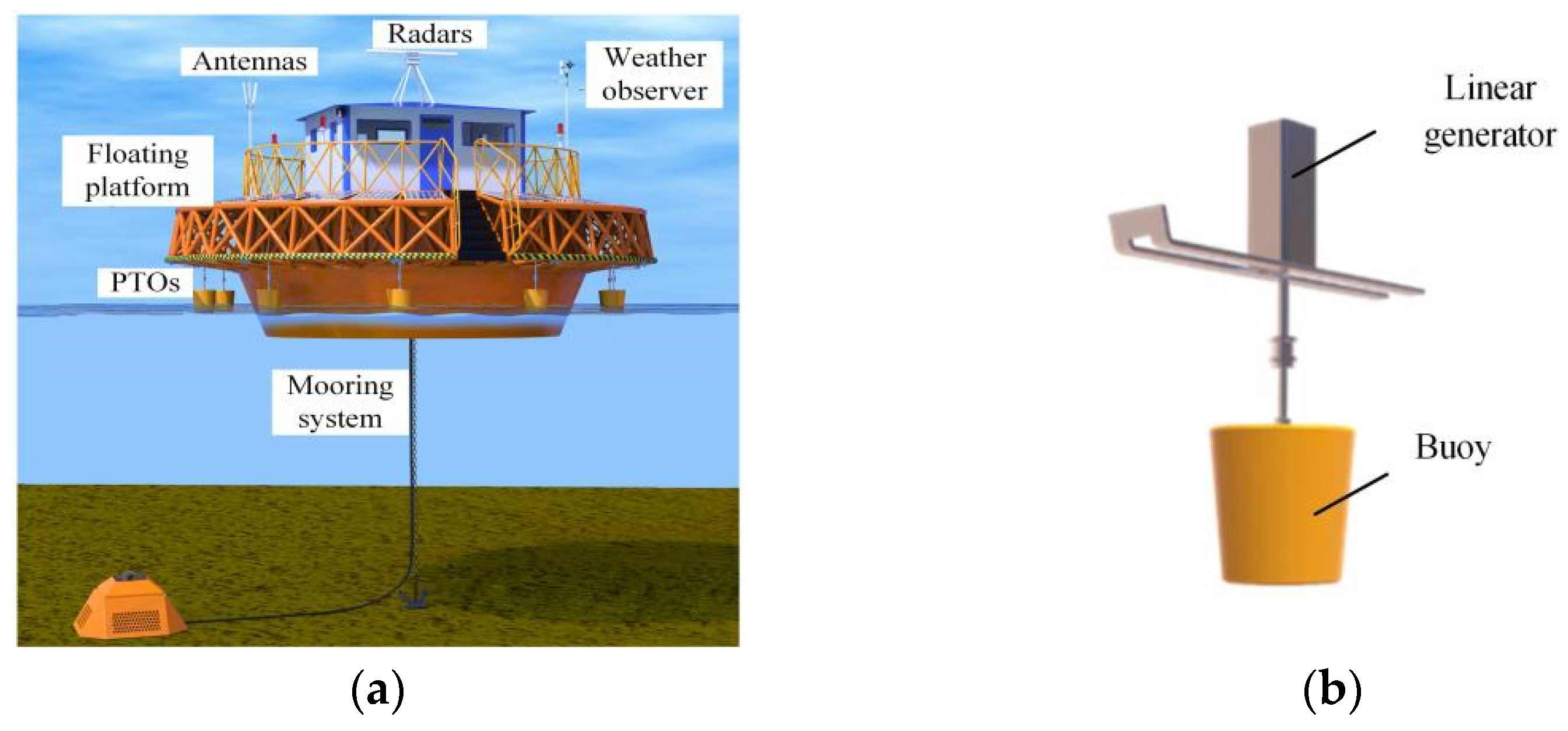
The ocean wave convert system proposed in this paper consists of a floating platform, several DD-WECs, and the mooring system, as shown in Figure 1. Furthermore, devices with different functions can be installed on the platform, such as radars, weather observers, batteries, and so on [26]. All the components together make up a microgrid, which can utilize wave energy to supply this equipment or store it in the batteries. The DD-WEC in this system is merely composed of a buoy and a linear generator (LG), in which the wave energy is captured by the buoy. The translator of the LG is directly coupled to the heaving buoy and the stator is mounted on the platform. When the incident waves excite the buoy and platform in the vertical direction simultaneously, the motion of the floating platform, which is fastened by the anchor, is much smaller than the buoy. Therefore, there is a relative speed between the buoy and the platform (i.e., the stator and the translator). Then, windings mounted in the stator of the LG will induce a voltage and generate electricity continuously. Figure 1 shows that there are several small DD-WECs distributed around the platform and that all of them can convert the wave energy to electricity. This design improves the survivability and reliability of the wave energy conversion system under extreme ocean weather. Moreover, even if some of the DD-WECs are damaged by the enormous waves, the remaining machines can still support the operation of the equipment. Meanwhile, replacing the broken DD-WECs will be cheap and convenient because of their small volume and light weight. On the other hand, the small volume of the DD-WEC requires the LG to have a high power density and power output in the restricted space. Therefore, the PMs are widely applied in linear generators to increase power density. However, the PM machines usually suffer a large detent force, especially in the interior PM machines, which affects the stable operation of the small direct-drive power generation system. For this reason, the influence of the detent force in small WECs is analyzed in the following part.

2.2. Influence Analysis of Detent Force in WEC

Because the wave velocity in the experimental tank is simplified in sinusoidal and conforms to the characteristics of regular (linear) waves, the motion equation of the buoy can be described in the frequency domain. According to Newton’s second law, the equation of the motion of the buoy in the vertical direction is
i ω m b v ^ b = f ^ e x + f ^ r a + f ^ h s + f ^ g e + f ^ f r
where i is the imaginary number, m b is the weight of the buoy, v ^ b is the moving speed of the buoy, f ^ e x is the vertical excitation force of the wave, f ^ h s is the hydrostatic force, f ^ r a is the wave radiation force, f ^ g e is the electromagnetic force of the generator, f ^ f r is the friction force; the symbol “^” denotes a frequency domain expression, the acceleration of the buoy is a ^ b = i ω v ^ b = ω 2 z ^ b ,   z ^ b is the displacement of the buoy in the vertical direction, and ω is the angular frequency. From motion equation, it can be seen that the speed of the buoy is related to different forces. Therefore, the following analysis is applied to the different forces.
Hydrostatics is the restoring force of the buoy due to the displacement under the still water. Its magnitude is related to the displacement and is calculated as:
f ^ h s = ρ g S z ^ b
where S is the static water cross-section (for the cylindrical buoy, i.e., the bottom area of the buoy), ρ is the density of water.
The composition of the electromagnetic force is different under no-load and load conditions. In the no-load state, the electromagnetic force is mainly composed of the detent force f ^ D e t . In the load state, f ^ g e is the combined force of the detent force f ^ D e t and electromagnetic force f ^ L o a d generated by the load. In order to analyze the influence of the detent force on the WEC more simply, it can be assumed that f ^ g e = f ^ D e t . The exact electromagnetic force is calculated by Maxwell, one of the business finite element analysis (FEA) software. The friction force is generated by the friction between the bearings of MI-TLPMGs and the moving parts of the wave power generation system, which can be depicted as
f ^ f r = i ω R f r z ^ b
where R f r is the coefficient of friction.
As the main interaction force between the buoy and the moving waves, f ^ e x and f ^ r a have a decisive impact on the hydrodynamic equation of the WEC. They are solved separately by using the potential flow theory. The fluid pressure on the bottom of the buoy is the main source of its wave force, therefore the wave excitation force can be described as
f ^ e x = S P n 1 d S
where P is the pressure, n 1 is the unit normal vector and is in the same direction as the z-axis. According to the Bernoulli equation, the pressure is expressed as
P = i ω ρ ϕ
where ϕ is the wave velocity potential. Substituting Equation (5) into Equation (4) yields:
f ^ e x = i ω ρ S ϕ n 1 d S
If the fixed buoy is released to the free movement state, the wave excitation force actuates it, and the wave nearby oscillates in the vertical direction. Conversely, the waves will react to the buoy. Therefore, it will produce a radiation force
f ^ r a = i ω v ^ b ( m a ζ d i ω ) = m a a ^ b ζ d v ^ b
where m a is the added mass, ζ d is the damping coefficient. Substituting Equations (2), (3), (6) and (7) into (1), the velocity and displacement of the buoy and linear generator are described as
z ^ b = i ω ρ S ϕ n 1 d S + f D e t ω 2 ( m a + m b ) + i ω ( R f r + ζ d ) + ρ g S b
v ^ b = i ω ρ S ϕ n 1 d S + f D e t i ω ( m a + m b ) + ( R f r + ζ d ) + ρ g S b / i ω
From the above equations, it can be seen that the speed and buoy are affected by the detent force, which determines the shape and amplitude of the induced back electromotive force. To validate the analysis results, an experiment has been conducted in the wave tank as shown in Figure 2. Based on a wave maker at the end of the tank, ocean waves with different heights and periods are produced to simulate the ocean waves. In the experiments, the ocean waves were assumed to be sinusoidal waves created by the flume with a period of 2 s and a wave height of 0.3 m. Due to the limited width of the flume, the radius, height, and thickness of the float is chosen to be 0.3 m, 0.5 m, and 0.002 m, respectively, in order to reduce the influence of the flume walls on the movement of the floats. The floats were also made of stainless steel to prevent corrosion and rusting.
Figure 3 shows that the wave reaches the maximum vertical velocity of 0.48 m/s at 0.5 s, and the buoy also reaches the maximum velocity of 0.28 m/s at the nearby time. Since the buoy is rigidly connected to the linear generator, they have the same moving speed. Nevertheless, the speed curve is not smooth and fluctuates with time, which is mainly caused by the detent force of the linear generator. Figure 4 shows the three-phase induced back EMF waveforms of the linear generator driven by the buoy. The back EMF waveforms have a large fluctuation, which will affect the output power and wave energy conversion efficiency. Therefore, it is necessary to optimize and minimize the detent force in the small wave energy conversion device.

3. Detent Force Optimization of MI-TLPMG

3.1. Proposed Structure

MI-TLPMGs on the platform supply all these applications by extracting energy from ocean waves and converting it into electricity. Figure 5 shows the cross-sections schematic of the proposed MI-TLPMG in this paper. It consists of armature winding, a stainless steel shaft, multilayer embedded permanent magnets, a primary iron core, and a secondary iron core. The embedded PMs are composed of symmetrical five-layer annular permanent magnets, which are called the main PM, the secondary PM, and the auxiliary PM, as shown in Figure 6. The flux concentrating effect produced by the multilayer embedded permanent magnets with axial magnetization improves the power density and induces voltage.
To further verify the advantages of MI-TLPMG, the electromagnetic performance of linear cylindrical generators with radial magnetization (RS-TLPMG) and quasi-Halbach array magnets (QH-TLPMG) is compared and analyzed under the same volume and speed. Compared with RS-TLPMG and QH-TLPMG, the induced electromotive force and output power of MI-TLPMG is about 37.5 V and 47.2 W, which is about two- and three-times more than that of RS-TLPMG and QH-TLPMG, respectively, as shown in Figure 7. More importantly, the PMs of the MI-TLPMG are no longer exposed but completely wrapped with an iron core, thus avoiding seawater erosion and wave crash, and improving the survivability and service life of the generator. However, compared with other PM machines, the detent force of the MI-TLPMG with multilayer embedded PMs is more serious. Consequently, it should be optimized and minimized to prevent it from affecting the stable operation and energy conversion of DD-WECs.
The detent force of the permanent magnet linear motor is caused by the mutation of the magnetic co-energy and discontinuous stator and mover, which can be described as follows:
F det = W c z
W c = W a i r + W p m = 1 2 μ 0 V B 2 d V
where W a i r and W p m are the air gap and permanent magnet magnetic energy, respectively, V is the integral volume, and B is the magnetic flux density. Therefore, the detent force of the MI-TLPMG mainly includes end force and cogging force, and the weakened method is used to make its air gap permeance change more smoothly. The arc-shaped auxiliary tooth and salient pole auxiliary tooth are proposed in [27,28] to decrease the end force. However, the auxiliary slot will increase the length of the primary back iron. Especially for the MI-TLPMG, it improves the primary mass and volume. Meanwhile, the MI-TLPMG adopts multilayer embedded PMs, which concentrate the magnetic flux lines in the adjacent iron core. Therefore, the permeability variation between the iron core and the permanent magnet is large, which makes the permeability change significantly, and the detent force increases accordingly.
To solve the problem, this paper proposes the L-shaped auxiliary tooth and interpole magnetic barrier to optimize the detent force of MI- TLPMG, as shown in Figure 8. Figure 8a depicts the parameters such as the height h t a , h t b and width w t a , w t b of the L-shaped auxiliary tooth. The interpole magnetic barrier is symmetrical of the midline of the two adjacent magnet poles, and the main structure parameters are the height y m h and width y m w , as shown in Figure 8b.
Figure 9 shows the distribution of flux lines in the MI-TLPMG after adopting the hybrid optimizing structure for detent force. As can be seen in Figure 9, with the L-shaped auxiliary tooth, the flux lines enter the primary through the teeth, enabling the magnetic field at the end to vary smoothly. Simultaneously, the flux passing through the auxiliary tooth interacts with other phase windings at the end, which balances the three-phase induced voltages. The auxiliary teeth are arranged close to the windings to minimize the length and weight of the primary. The interpole magnetic barrier prevents the flux lines from concentrating excessively towards the middle of the poles, resulting in a more even magnetic flux distribution in this area. The optimization of both the structure and flux lines above leads to a smoother change in air-gap permeability during the operation of the MI-TLPMG, thus significantly reducing detent force.

3.2. Optimization Based on the Taguchi Method

According to the proposed structure for optimizing the detent force, the number of parameters involved for the auxiliary tooth and magnetic barrier is large, and the optimization process is tedious. If the general optimization method is used, i.e., one of the parameters is optimized first, and then the other parameters are optimized one by one after the first target has been reached. This parameter-by-parameter optimization method may achieve certain optimization results. Nevertheless, there is a non-linear, strongly coupled, and inter-constrained relationship between the parameters, resulting in results that are not optimal. Therefore, in this section, the Taguchi method is used to optimize the detent force, and the multi-parameter synergistic optimization results are achieved in a short time.
Several concepts are involved in the Taguchi optimization process, such as control factors, signal factors, noise factors, quality characteristics, factor levels, orthogonal test tables, etc. The parameters that influence the positioning force are defined as factors, including controllable variables such as the width w t a , w t b and height h t a , h t b of the auxiliary teeth and the height y m h and width y m w of the interpolar magnetic barrier. At the same time, there are also uncontrollable noise factors such as manufacturing errors, assembly errors, and material quality. There are also artificially set parameters that indicate the desired value of the signal factor.
In order to achieve the best quality characteristics, different values are selected for each factor, which are called factor levels. The number of factors and factor levels, as well as their combined arrangement, form a complete test space. Experiences are arranged scientifically and rationally by means of an orthogonal test table. The orthogonal table is a multifactorial test table arranged according to the law of orthogonality, which is balanced and regular, i.e., each factor has the same weight. The process of applying the Taguchi method to optimize the detent force is shown in Figure 10.
There are six control factors X, Y, A, B, C, and D in the detent force optimization, which correspond to the structural parameters y m h , y m w , h t a , w t a , h t b , and w t b in Figure 8. Three levels were selected for each control factor, which are distributed around the initial value and in an equal series, as shown in Table 1.
According to the law of permutations, when the number of factors is 6 and the number of levels is 3. To obtain the optimum parameters, the finite element model needs to be calculated 36 = 729 times. However, if the Taguchi method is used to create the orthogonal experiment table, only 27 calculations are required. The different combinations of the factor levels are entered into the finite element model to obtain the following Table 2 of detent forces. The amplitude of the detent force is defined as
F det = max ( F det ) min ( F det ) 2

3.3. Optimization Results

To analyze the effect of different factor levels on the detent force of MI-TLPMG, the FEA results were analyzed using the mean and signal-to-noise(S/N) ratio. The mean value is the average response for each combination of control factor levels using the Taguchi method, and the expression is
F a v g ( α i ) = 1 m j = 1 m F d e t ( α i j )
where α is the control factor, i is the factor level, and m is the number of experiences within the factor levels.
The signal-to-noise ratio is a measure of robustness. According to the different signal-to-noise ratios of the response targets, there are three different types of signal-to-noise ratios, such as larger-is-better, nominal-is-best, and smaller-is-better. In this section, in order to minimize the detent force, the smaller-is-better ratio is used.
{ S / N = 10 × log ( ( 1 / F ¯ ) / n ) S / N = 10 × log ( ( F ¯ 2 ) / σ 2 ) S / N = 10 × log ( ( F 2 ) / n )
The mean values and signal-to-noise ratios of each control factor are obtained based on the experimental results and Equations (13) and (14), as shown in Table 3 and Table 4. It can be seen from Figure 11 and Figure 12 that the control factors X, Y, A, B, C, and D have different effects on the localization power and signal-to-noise ratio in each of the three levels. Among them, factor level X2, factor level Y2, factor level A2, factor level B2, factor level C3, and factor level D2 cause the smallest mean value of localization power and the largest signal-to-noise ratio, respectively.
The values of D a v g and D s n for each control factor parameter based on the above equations are shown in Table 5. The analysis shows that the relative importance of the different control factors on the optimization of the mean value and signal-to-noise ratio is ranked from strong to weak as A, X, Y, B, D, and C.
Therefore, the optimal parameters of the L-shaped auxiliary teeth and interpole magnetic barrier for optimizing the positioning force of the MI-TLPMG motor based on the Taguchi method is A(2)X(2)Y(2)B(2)C(3)D(2), and their corresponding values are shown in Table 6. Therefore, based on the Taguchi method to minimize the detent force of MI-TLPMG, the optimal parameter combination of the L-shaped auxiliary teeth and the magnetic barrier is A(2)X(2)Y(2)B(2)C(3)D(2), whose corresponding values are shown in Table 6.
The optimal parameters obtained by the Taguchi method are input into the finite element model to calculate the optimized positioning force, and the waveforms of the detent force before and after the optimization are illustrated in Figure 13. It can be seen from the figure that, after the optimization by the Taguchi method, the amplitude of the detent force is reduced from the initial 21.7 N to 5.2 N, which means it has weakened by nearly 76.1%. Thus, the feasibility of this method in the optimization of the detent force of the MI-TLPMG is demonstrated.

4. Experiment

After obtaining the optimization parameters, a prototype of MI-TLPMG is manufactured, and the secondary and primary parts are shown in Figure 14. The key parameters of the MI-TLPMG are shown in Table 7. It is installed on the test platform to test the detent force of MI-TLPMG, as shown in Figure 15. The test platform includes a control box, force sensor, driving motor, connecting rod, and oscilloscope. The experimental results are shown in Figure 16, which verifies the validity of the above method. However, the experimental measurement data are slightly higher than the simulation value. The amplitude of the detent force measured in the experiment is 7.5 N, which is considered to be consistent with the simulation results.
Due to the width of the wave tank and the depth of water stored in the tank, the radius and height of the buoy cannot be too large. At the same time, to limit its weight, the walls of the float should be as thin as possible while maintaining mechanical strength. Based on the above considerations, the geometry and mass of the float were determined as shown in Table 8. The direct-drive wave power system based on the MI-TLPMG was built to verify the electromagnetic characteristics after the detent force optimization in the wave tank. The DD-WEC mainly consists of a floating buoy, the MI-TLPMG, the connecting shaft, crossbeams, the support platform, and table clamps, as shown in Figure 17. The principle is that the float drives the MI-TLPMG with the movement of the waves. As the primary is fixed in the middle of the wave tank by the support platform and crossbeams, a relative motion is generated between the primary and secondary of the MI-TLPMG. The primary winding cuts the magnetic flux, thus converting wave energy into electrical energy.
Once all components have been commissioned and installed, the wave flume is activated to create waves with sinusoidal speed motion, driving the MI-TLPMG to convert the wave energy into electricity. In order to record the actual operation of the generator wave tank, the power analyzer WT1800 is used to record the output voltage waveform. Figure 18 shows the output voltage waveforms of wave height H = 0.3 m and period T = 1.5 s, and wave height H = 0.3 m and period T = 1.2 s, respectively. The figures show that the MI-TLPMG secondary operations at a sinusoidal speed in the vertical direction driven by the wave and the output voltage waveform is regular. When the float is at its highest or lowest point, the generator speed and output voltage values are both zero. When the float is in the equilibrium position, the generator moves at a maximum speed and the output voltage reaches a maximum value of 29.4 V and 42.5 V. Due to the optimization of the detent forces in the previous section, the mechanical vibrations generated during the operation of the generator are not noticeable, and the voltage waveforms are smooth and less burly.

5. Conclusions

In this paper, a novel MI-TLPMG for DD-WEC, which consists of multilayer and interior permanent magnets, is proposed to avoid the erosion of seawater and the impact of waves. However, because the detent force of an MI-TLPMG with multilayer embedded PMs is more serious, the L-type auxiliary teeth and interpole magnetic barriers are introduced to minimize the detent force of the MI-TLPMG. In addition, the detent force is optimized according to the principle of the Taguchi method. Finally, a prototype has been manufactured and measured in the wave tank to verify the optimization results. Through the calculations, the following conclusions are presented:
(1) Compared with traditional RS-TLPMG and QH-TLPMG, the back EMF and output power of the proposed MI-TLPMG are about 37.5 V and 47.2 W, which are two- and three-times higher than those of RS-TLPMG and QH-TLPMG, respectively. This can improve the problems of low power density and the induced voltage of the linear generators;
(2) The multi-parameter synergistic optimization result is achieved in a short time by reducing the times of the FEA calculations from 729 to 27 based on the Taguchi method, which ensures the optimization effect and reduces the workload and time cost;
(3) The detent force is significantly reduced by optimizing the height and width of the L-type auxiliary teeth and interpole magnetic barriers. The FEA results show that the amplitude of the detent force is reduced from the initial 21.7 N to 5.2 N after optimization, which means that it has weakened by nearly 76.1% compared with preoptimization.
The L-type auxiliary teeth and interpole magnetic barriers proposed in this article will be applied to other permanent magnet linear motors in the future, in particular, the interior permanent magnet linear motors, which can significantly reduce the number of calculations while decreasing detent forces. Meanwhile, we will optimize the shape of the interpolar magnetic barriers and the L-shaped auxiliary teeth by replacing the rectangular shape with a curved shape to obtain a better result.

Author Contributions

Conceptualization, T.X.; methodology, software, T.X. and Y.Z.; validation, T.X. and Y.X.; formal analysis, T.X. and P.H.; investigation, resources, data curation, T.X., H.L. and Y.X.; writing—original draft preparation, T.X. and H.L.; writing—review and editing, T.X., H.L. and P.H.; visualization, Y.X.; supervision, Y.Z.; project administration, Y.Z.; funding acquisition, T.X. All authors have read and agreed to the published version of the manuscript.

Funding

This research was funded by the National Natural Science Foundation of China under Grants 41576096 and 41876096, Youth Fund of Jiangsu Natural Science Foundation under BK20201034, Jiangsu Distribution Network Intelligent Technology and Equipment Collaborative Innovation Center under XTCX202002, Natural Science Research Project of Jiangsu Higher Education Institutions under Grant 20KJB470028 and Scientific Research Fund of Nanjing Institute of Technology (YKJ2019115).

Institutional Review Board Statement

Not applicable.

Informed Consent Statement

Not applicable.

Data Availability Statement

Not applicable.

Conflicts of Interest

The authors declare no conflict of interest.

References

  1. Díaz, H.; Soares, C.G. Review of the current status, technology and future trends of offshore wind farms. Ocean. Eng. 2020, 209, 107–381. [Google Scholar] [CrossRef]
  2. Elkholy, A.M.; El-Ghany, H.A.A.; Azmy, A.M. General framework for intentional islanding to enhance distribution system performance. Electr. Power Compon. Syst. 2020, 48, 1488–1507. [Google Scholar] [CrossRef]
  3. Li, Z.; Ghia, K.; Fan, Z.; Li, Y.; Shen, L. Unsteady Reynolds-Averaged Navier-Stokes Investigation of free surface wave impact on tidal turbine wake. Proc. Roy. Soc. 2021, 477, 20200703. [Google Scholar] [CrossRef]
  4. Pinto, S.O.; Santos, P.R.; Pinto, F.T. Assessment of the potential of combining wave and solar energy resources to power supply worldwide offshore oil and gas platforms. Energy Convers Manag. 2020, 223, 113299. [Google Scholar] [CrossRef]
  5. Zhang, Y.; Li, G. Non-causal linear optimal control of wave energy converters with enhanced robustness by sliding mode control. IEEE Trans. Sustain. Energy 2020, 11, 2201–2209. [Google Scholar] [CrossRef]
  6. Dewhurst, T.; Sivakumar, S. Wave-to-wire modeling and simulation of a wave energy converter for off-grid and micro-grid applications. In Proceedings of the OCEANS 2018 MTS/IEEE Charleston, Charleston, SC, USA, 22–25 October 2018; pp. 1–8. [Google Scholar]
  7. Garcia-Rosa, P.B.; Torres-Olguin, R.E.; Cruz, J.; D’Arco, S. A wave-to-wire model for grid integration studies of oscillating-body wave energy converters. In Proceedings of the 2022 IEEE 31st International Symposium on Industrial Electronics (ISIE), Anchorage, AK, USA, 1–3 June 2022; pp. 84–91. [Google Scholar]
  8. Ahamed, R.; Mckee, K.; Howard, I. Advancements of wave energy converters based on power take off (PTO) systems: A review. Ocean. Eng. 2020, 204, 107248. [Google Scholar] [CrossRef]
  9. Faiz, J.; Nematsaberi, A. Linear electrical generator topologies for direct-drive marine wave energy conversion-an overview. IET Renew. Power Gener. 2017, 11, 1163–1176. [Google Scholar] [CrossRef]
  10. Kojimoto, N.C.; Lehmann, M.; Murray, B.; Boerner, T.; Alam, M.R. Model scale submerged hydraulic power takeoff with adjustable damping for wave energy conversion. In Proceedings of the 27th International Ocean and Polar Engineering Conference of International Society of Offshore and Polar Engineers, San Francisco, CA, USA, 25–30 June 2017; pp. 1–6. [Google Scholar]
  11. Huang, X.; Sun, K.; Xiao, X. A Neural Network-Based Power Control Method for Direct-Drive Wave Energy Converters in Irregular Waves. IEEE Trans. Sustain. Energy 2020, 11, 2962–2971. [Google Scholar] [CrossRef]
  12. Khatri, P.; Wang, X. Comprehensive review of a linear electrical generator for ocean wave energy conversion. IET Renew. Power Gener. 2020, 14, 949–958. [Google Scholar] [CrossRef]
  13. Augusto Santana Castelo Branco, C.; Antonio de Souza Ribeiro, L.; Gomes de Matos, J.; Mendonça, H.; Ronald Saavedra, O.; Araújo Oliveira, H. Modeling of Direct-Drive Point Absorber Wave Energy Converters. In Proceedings of the IECON 2021—47th Annual Conference of the IEEE Industrial Electronics Society, Toronto, ON, Canada, 13–16 October 2021; pp. 1–6. [Google Scholar]
  14. Jin, C.; Kang, H.; Kim, M.; Bakti, F.P. Performance evaluation of surface riding wave energy converter with linear electric generator. Ocean. Eng. 2020, 218, 108141. [Google Scholar] [CrossRef]
  15. Dong, D.; Huang, W.; Bu, F.; Wang, Q. Modeling and Optimization of a Tubular Permanent Magnet Linear Motor Using Transverse-Flux Flux-Reversal Topology. IEEE Trans. Ind. Appl. 2019, 55, 1382–1391. [Google Scholar] [CrossRef]
  16. Zhao, L.; Lu, Q.; Chen, R. A novel tubular partitioned stator flux-reversal permanent magnet linear machine for direct-drive wave energy generation. IEEE Trans. Magn. 2019, 5, 1–7. [Google Scholar] [CrossRef]
  17. Huang, L.; Liu, J.; Yu, H.; Qu, R.; Chen, H.; Fang, H. Winding Configuration and Performance Investigations of a Tubular Superconducting Flux-Switching Linear Generator. IEEE Trans. Appl. Supercond. 2015, 25, 1–5. [Google Scholar] [CrossRef]
  18. Huang, L.; Hu, M.; Liu, J.; Yu, H.; Zeng, C.; Chen, Z. Electromagnetic Design of a 10-kW-Class Flux-Switching Linear Superconducting Hybrid Excitation Generator for Wave Energy Conversion. IEEE Trans. Appl. Supercond. 2017, 27, 1–6. [Google Scholar] [CrossRef]
  19. Niknafs, S.; Shiri, A.; Bagheri, S. Design and optimization of air-cored double-sided linear permanent magnet generators for wave energy conversion. Energy Sci. Eng. 2022, 1–15. [Google Scholar] [CrossRef]
  20. Bai, J.; Liu, B.; Qiao, G.; Liu, G.; Liu, Y.; Zheng, P. Design and Analysis of a Novel Tubular High-PM-Utilization Transverse-Flux Linear Machine. IEEE Trans. Magn. 2022, 58, 1–5. [Google Scholar] [CrossRef]
  21. Zhou, R.; Zhao, B.; Shi, W.; Qi, C. Detent Force Minimization of Permanent Magnet Linear Synchronous Motor based on Arc-Teeth. In Proceedings of the 2020 IEEE International Conference on Applied Superconductivity and Electromagnetic Devices, Tianjin, China, 16–18 October 2020; pp. 1–3. [Google Scholar]
  22. Souissi, A.; Abdennadher, I.; Masmoudi, A. An Approach to Reduce the Detent Force of Double-Sided Flat Linear PMSMs. In Proceedings of the 2021 Sixteenth International Conference on Ecological Vehicles and Renewable Energies (EVER), Monte-Carlo, Monaco, 5–7 May 2021; pp. 1–6. [Google Scholar]
  23. Wang, W.; Zhao, J.; Song, J.; Dong, F.; Zong, K.; Li, G. Thrust performance improvement for PMSLM through double-layer reverse skewed coil and wrf-mkh method. IEEE/ASME Trans. Mechatron. 2020, 25, 2950–2960. [Google Scholar] [CrossRef]
  24. Zhang, H.; Kou, B.; Zhu, Z.Q.; Qu, R.; Luo, J.; Shao, Y. Thrust Ripple Analysis on Toroidal-Winding Linear Permanent Magnet Vernier Machine. IEEE Trans. Ind. Electron. 2018, 65, 9853–9862. [Google Scholar] [CrossRef]
  25. Seo, S.W.; Jang, G.H.; Koo, M.M.; Choi, J.Y. Characteristic analysis of the influence of auxiliary teeth and notching on the reduction of the detent force of a permanent magnet linear synchronous machine. IEEE Trans. Appl. Supercond. 2018, 28, 1–5. [Google Scholar] [CrossRef]
  26. Xia, T.; Yu, H.; Shi, Z.; Guo, R. Comparative Analysis and Experimental Verification of a Linear Tubular Generator for Wave Energy Conversion. Energies 2018, 11, 1707. [Google Scholar] [CrossRef] [Green Version]
  27. Kim, S.-J.; Park, E.-J.; Jung, S.-Y.; Kim, Y.-J. Optimal Design of Reformed Auxiliary Teeth for Reducing End Detent Force of Stationary Discontinuous Armature PMLSM. IEEE Trans. Appl. Supercond. 2016, 26, 1–5. [Google Scholar] [CrossRef]
  28. Chen, M.; Huang, L.; Tan, P.; Li, Y.; Ahmad, G.; Hu, M. A Stator-PM Transverse Flux Permanent Magnet Linear Generator for Direct Drive Wave Energy Converter. IEEE Access 2021, 9, 9949–9957. [Google Scholar] [CrossRef]
Figure 1. The configuration of wave energy conversion system: (a) A description of the proposed floating platform. (b) A three-dimensional view of the WEC with MI-TLPMG.
Electronics 11 03896 g001
Figure 2. The wave tank test platform.
Electronics 11 03896 g002
Figure 3. The velocity of the wave and buoy at the wave tank.
Electronics 11 03896 g003
Figure 4. The three-phase back EMF of the linear generator.
Electronics 11 03896 g004
Figure 5. The structure of 7 poles/6 slots MI-TLPMG.
Electronics 11 03896 g005
Figure 6. The 3D structure of the multilayer embedded permanent magnets.
Electronics 11 03896 g006
Figure 7. The electromagnetic performance of MI-TLPMG: (a) The induced electromotive force. (b) The comparison of output power.
Electronics 11 03896 g007
Figure 8. The detent force optimization structure of the MI-TLPMG: (a) L-shaped auxiliary tooth. (b) The interpole magnetic barrier.
Electronics 11 03896 g008
Figure 9. Distribution of magnetic lines with optimized structures.
Electronics 11 03896 g009
Figure 10. The optimizing process of the detent force based on Taguchi method.
Electronics 11 03896 g010
Figure 11. The effect of each factor level on the mean value of the detent force.
Electronics 11 03896 g011
Figure 12. The effect of each factor level on the signal-to-noise ratio.
Electronics 11 03896 g012
Figure 13. Detent force waveforms before and after optimization with Taguchi.
Electronics 11 03896 g013
Figure 14. The secondary and primary structure of the MI-TLPMG.
Electronics 11 03896 g014
Figure 15. MI-TLPMG detent force test platform.
Electronics 11 03896 g015
Figure 16. Simulation and experimental waveforms of detent force.
Electronics 11 03896 g016
Figure 17. Wave tank experiment based on MI-TLPMG power generation system.
Electronics 11 03896 g017
Figure 18. The output voltage waveform of MI-TLPMG at different wave speeds: (a) H = 0.3 m, T = 1.5 s. (b) H = 0.3 m, T = 1.2 s.
Electronics 11 03896 g018
Table 1. Level distribution of different factors.
Control FactorsLevel 1 (mm)Level 2 (mm)Level 3 (mm)
X ( y m h )11.52
Y ( y m w )456
A ( h t a )171819
B ( w t a )33.54
C ( h t b )456
D ( w t b )2.53.54.5
Table 2. Orthogonal test table and results.
Test NumberTest Orthogonal Table F det
XYABCD
11417342.545.75
21417353.535.2
31417364.528.75
415183.542.511.2
515183.553.55.45
615183.564.59
71619442.511.15
81619453.521.55
91619464.529.35
101.5418443.58.05
111.5418454.510.85
121.5418462.56.6
131.5519343.510.85
141.5519354.521
151.5519362.57.3
161.56173.543.515.85
171.56173.554.511.15
181.56173.562.521.75
1924193.544.525.1
2024193.552.57.65
2124193.563.514.85
222517444.59.5
232517452.518.3
242517463.513.05
252618344.57.45
262618352.516.3
272618363.56.55
Table 3. Mean values of the detent force at different levels of each factor.
FactorsXYABCD
Levels
121.93320.31122.14419.90616.116.222
212.6 11.7399.0513.55616.38314.6
313.19415.67816.53314.26715.24416.906
Table 4. The signal-to-noise ratio at different levels for each factor (dB).
FactorsXYABCD
Levels
1−25.01−24.18−25.79−23.97−22.55−22.52
2−21.26−20.7−18.67−21.73−23.07−21.91
3−21.58−22.96−23.39−22.14−22.23−23.41
Table 5. Ranking the importance of each factor on mean value and signal-to-noise ratio.
FactorsXYABCD
D a v g 9.3338.57213.0946.351.1392.306
D s n 3.75 3.487.122.240.831.5
Rank231465
Table 6. Optimized parameter values based on Taguchi method.
FactorsParametersLevelsValues (mm)
A h t a 218
X y m h 21.5
Y y m w 25
B w t a 23.5
C h t b 36
D w t b 23.5
Table 7. The key parameters of the MI-TLPMG.
ParameterMI-TLPMG
Pole slot ratio Pm/Ps7/6
Secondary inner diameter Rmi (mm)10
Secondary outer diameter Rmo (mm) 30
Air gap width Ga (mm)2.5
Primary inner diameter Rsi (mm)32.5
Primary outer diameter Rso (mm)60
Slot pitch τsw (mm)21
Tooth width τtw (mm)5
Polar pitch τpw (mm)18
Number of embedded PM layers A5
Main PM height β m h I (mm)19.6
Main PM width β m w I (mm)4
Sub PM width β m w II (mm)14
Sub PM height β m h II (mm)2
Auxiliary PM height β m h III (mm)7
Auxiliary PM width β m w III (mm)2
Winding turns100
Number of windings per phase4
Table 8. Float geometry and mass.
Float Radius (m)Float Height (m)Float Thickness (m)Float Mass (Kg)
0.30.50.00111.7
Publisher’s Note: MDPI stays neutral with regard to jurisdictional claims in published maps and institutional affiliations.

