Article

Implementation and Experimental Verification of Resistorless Fractional-Order Basic Filters

by
Dimitrios Patrinos
1,
Georgios Tsirmpas
1,
Panagiotis Bertsias
1,
Costas Psychalinos
1,* and
Ahmed S. Elwakil
2,3,4
1
Department of Physics, Electronics Laboratory, University of Patras, GR-26504 Rio Patras, Greece
2
Department of Electrical and Computer Engineering, University of Sharjah, Sharjah P.O. Box 27272, United Arab Emirates
3
Nanoelectronics Integrated Systems Center (NISC), Nile University, Giza 12677, Egypt
4
Department of Electrical and Software Engineering, University of Calgary, Calgary, AB T2N 1N4, Canada
*
Author to whom correspondence should be addressed.
Electronics 2022, 11(23), 3988; https://doi.org/10.3390/electronics11233988
Submission received: 4 November 2022 / Revised: 23 November 2022 / Accepted: 28 November 2022 / Published: 1 December 2022
(This article belongs to the Special Issue Feature Papers in Circuit and Signal Processing)

Abstract

:
Novel structures of fractional-order differentiation and integration stages are presented in this work, where passive resistors are not required for their implementation. This has been achieved by considering the inherent resistive behavior of fractional-order capacitors. The implementation of the presented stages is performed using a current feedback operational amplifier as active element and fractional-order capacitors based on multi-walled carbon nano-tubes. Basic filter and controller stages are realized using the introduced fundamental blocks, and their behavior is evaluated through experimental results.

1. Introduction

Integer-order calculus deals with differentiation described by the expression D t n f ( t ) d n f x d x n , where n is the (integer) order of the operation ( n Z ) . In fractional calculus, the differentiation is described by a formula of the same form, D t α f ( t ) d α f x d x α , but the order is now a real ( α R ) number. The Laplace transform of the fractional-order derivative of a function f ( t ) , for zero initial conditions, in the fractional domain is: L 0 D t α f ( t ) = s α F ( s ) , with s α being the fractional-order Laplacian operator [1]. Using this, the impedance of a fractional-order capacitor is given by (1)
Z = 1 C α s α ,
where the variable 0 < α < 1 represents the order of the element and the variable C α is the pseudo-capacitance in Farad/sec 1- α [2,3].
Fractional-order capacitors play a crucial role in the implementation of stages, which perform signal processing in the fractional domain. They have been used for implementing fractional-order controllers, filters, oscillators, biological tissues models, etc. [4,5,6,7,8,9,10,11]. Compared to their conventional integer-order counterparts, they offer the benefit of the extra degree of freedom in the design; this comes from the fact that the order is different from the other. As a result, the derived fractional-order controller structures offer better open-loop response shaping than that offered by their integer-order counterparts; fine adjustment of the slope of the attenuation gradient can be performed in the case of fractional-order filters; oscillators with extremely low/high frequency of oscillation can be implemented.
The implementation of fractional-order transfer functions can be performed in the following ways:
(i)
Substituting the capacitors of the conventional (i.e., integer order) stages by fractional-order capacitors. At this point, there are two alternatives: (a) utilizing real fractional-order capacitors [12,13,14,15,16,17,18,19,20] or (b) utilizing RC networks for emulating the behavior of fractional-order capacitors [21,22,23,24,25,26,27], and their derivation is based on the utilization of approximation tools such as Charef, Oustaloup, Matsuda, continued fraction expansion, and partial fraction expansion [28,29,30,31,32]. The first alternative is straightforward, but the main obstacle is the absence of commercially available fractional-order capacitors. The second one is more practical, but requires an increased number of passive components.
(ii)
Approximating fractional-order transfer functions by rational-integer-order transfer functions, which are derived using the aforementioned approximation tools [33,34]. This solution suffers from the increased circuit complexity in both active and passive components count and increased power demand.
Fractional-order differentiation and integration stages play a fundamental role in the synthesis of systems, which perform signal processing based on the concept of fractional calculus [5]. Implementations are based on the substitution of integer-order capacitors in the corresponding active RC stages by their fractional-order counterparts. This approach has been successfully followed in [12,13,14,15,16,17,19,20] for implementing fractional-order differentiators/integrators as well as simple low pass filter stages. As the resistors remain unaffected, a practical problem related to the values of the resistors occurs in cases where large time constants are required, for example in biomedical or control systems, due to their low frequency nature. This can be overcome through the utilization of active elements whose behavior is described by the transconductance parameter ( g m ), but this solution encounters the obstacle of being valid only under small-signal operation conditions. As a consequence, the dynamic range of the derived systems is limited.
The main contributions made in this work are the following:
(a)
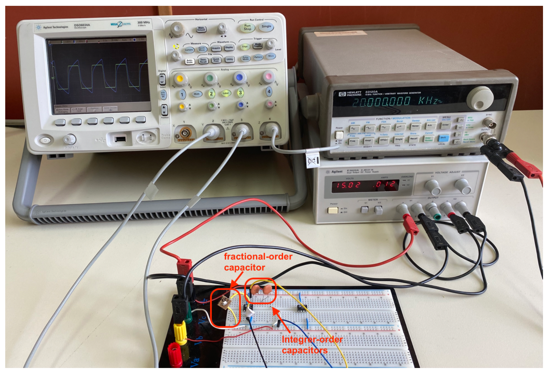
Novel scheme for implementing fractional-order differentiator/ integrator and filter stages are proposed in this work, where the presented structures are constructed only by capacitors and, therefore, avoiding the utilization of passive resistors.
(b)
The realized time constants are formed as a ratio of a conventional and a pseudo-capacitance, overcoming the restriction of small-signal operation.
The work is organized as follows: the differentiation and integration stages are presented in Section 2, where their benefits with regards to the conventional structures are also discussed. The filter design examples are provided in Section 3. The performance of the introduced structures is evaluated through experimental results in Section 4, where a fractional-order capacitor fabricated using multi-walled carbon nano-tubes (MWCNT) [18] and a current feedback operational amplifier (CFOA) as an active element, have been utilized.

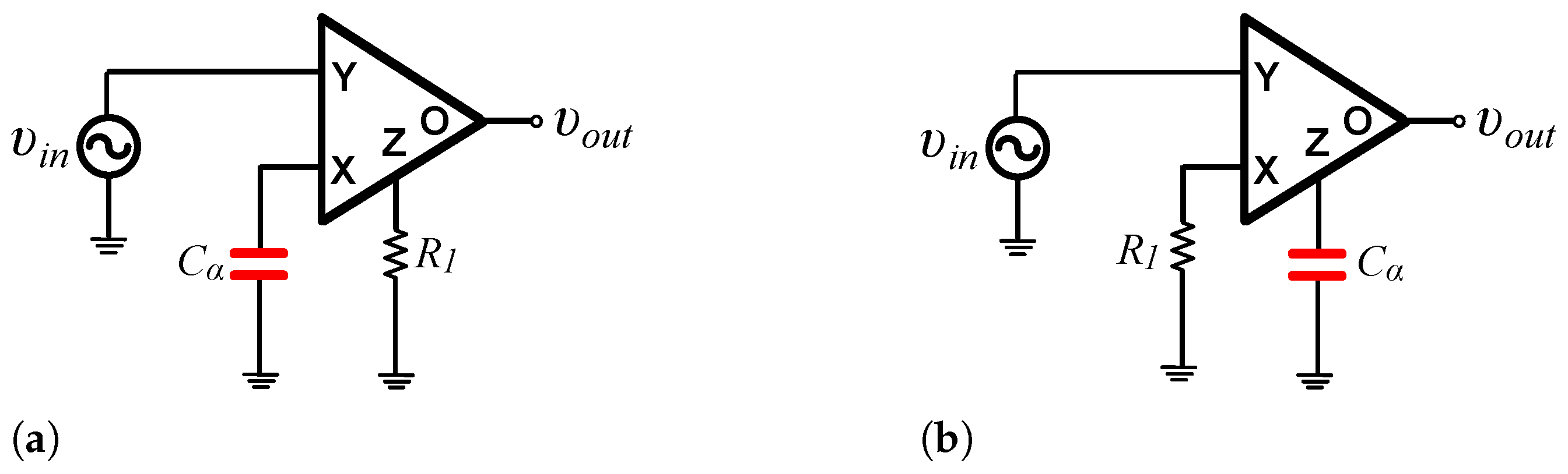
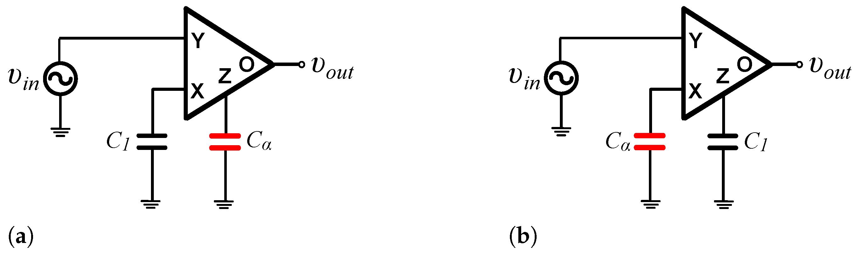
2. Novel Differentiation and Integration Stages

2.1. Proposed Topologies

Let us consider the typical CFOA-based fractional-order differentiator structure in Figure 1a, where the realized transfer function is
H ( s ) = R 1 C α s α ,
with C α being the pseudo-capacitance (in Farad/s1- α ) and 0 < α < 1 being the order of the differentiator [5]. The associated time constant has the form:
τ = ( R 1 C α ) 1 / α .
In the case of the fractional-order integrator, the corresponding topology is depicted in Figure 1b and the transfer function is given by (4)
H ( s ) = 1 R 1 C α s α ,
while the realized time constant is still given by (3).
Novel resistorless structures, alternatives to those in Figure 1, are proposed in this work. The transfer function realized by the topology in Figure 2a is
H ( s ) = C 1 C α s 1 α ,
with the order of the differentiator being equal to 1- α . The associated time constant is
τ = C 1 C α 1 1 α .
The topology in Figure 2b implements the transfer function of an integrator
H ( s ) = 1 C 1 C α s 1 α ,
with the associated time constant still given by the expression in (6).
Setting s α = ω α · [ cos ( α π / 2 ) + j sin ( α π / 2 ) ] , the expression in (1) expands as follows
Z = cos ( α π / 2 ) C α ω α + sin ( α π / 2 ) j C α ω α .
According to (8), the implementation of the time constant without using an actual resistor originates from the fact that the frequency behavior of a fractional-order capacitor is determined by both a “resistive” and a “capacitive” part, connected in series. Another important feature is that the implementation of the time constants in the resistorless structures in Figure 2 is performed without assuming small-signal operation, as it has been performed in the case of the topologies where the small-signal transconductance parameter ( g m ) is employed. This is achieved at the expense of losing the electronic tuning capability, offered by the aforementioned structures.

2.2. Comparison with the Conventional Implementations

For comparison purposes, let us consider that a time constant equal to 1 s will be realized. Assuming that the fractional-order capacitor has a pseudo-capacitance equal to 1 nF/s1- α , then according to (3) the value of the resistor must be equal to 1 G Ω , which is actually non-practical. Using (6) it is derived that an integer-order capacitor equal to 1nF is required and this is a reasonable value of capacitance.
Due to the absence of commercially available fractional-order capacitors, these elements can be approximated through the utilization of suitable passive RC networks such as the Foster and Cauer structures. In the cases, where the order has a relatively high value (i.e., α > 0.5 ) the practical problem, which arises is related to the increased spread of element values. A solution for overcoming this obstacle has been proposed in the literature, where the transfer function of the differentiator/integrator is formed by the product of the transfer functions of an integrator/differentiator of order equal to 1 α and of an integer-order differentiator/integrator, significantly increasing (almost doubling) the circuit complexity. The topologies in Figure 2 do not suffer from this problem because the order of capacitors for implementing differentiators/integrators of orders greater that 0.5 should be less than 0.5, as it is readily concluded from the transfer functions in (5) and (7). In the opposite cases, the topologies in Figure 1 are more preferable than the proposed ones. For demonstration purposes, let us consider the approximation of a capacitor of order α = 0.8 and pseudo-capacitance C α equal to 1 μF/s0.2. Using the Oustaloup approximation in the range [1, 104] rad/s, the passive elements values of the corresponding Foster-I network, rounded to the E48 series defined in IEC 60063, are summarized in Table 1. The corresponding ones in the case of a capacitor with the same value of the pseudo-capacitance and order α = 0.2 are provided in Table 2, where the reduction in the spread of the component values is evident.

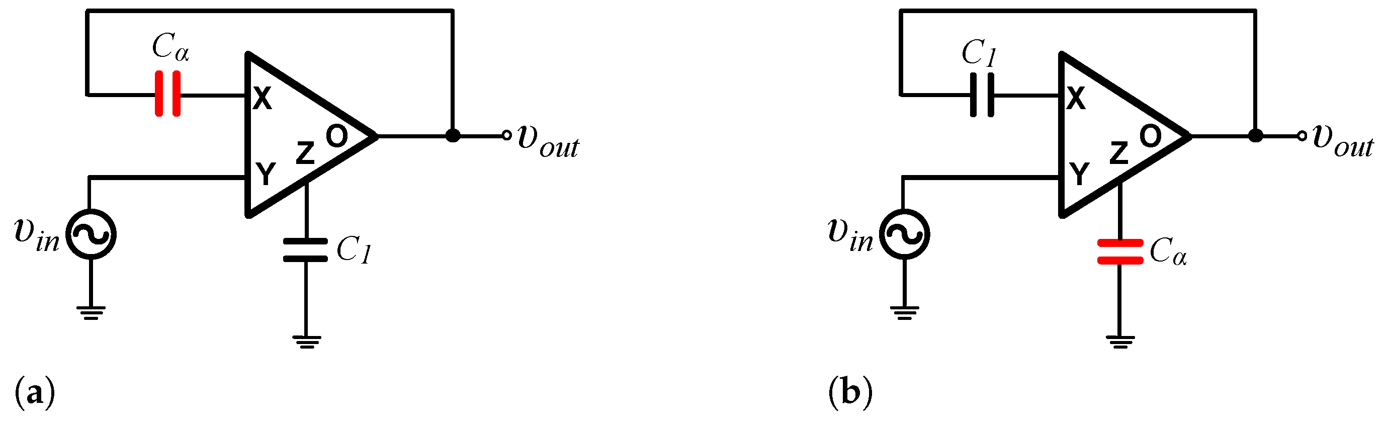
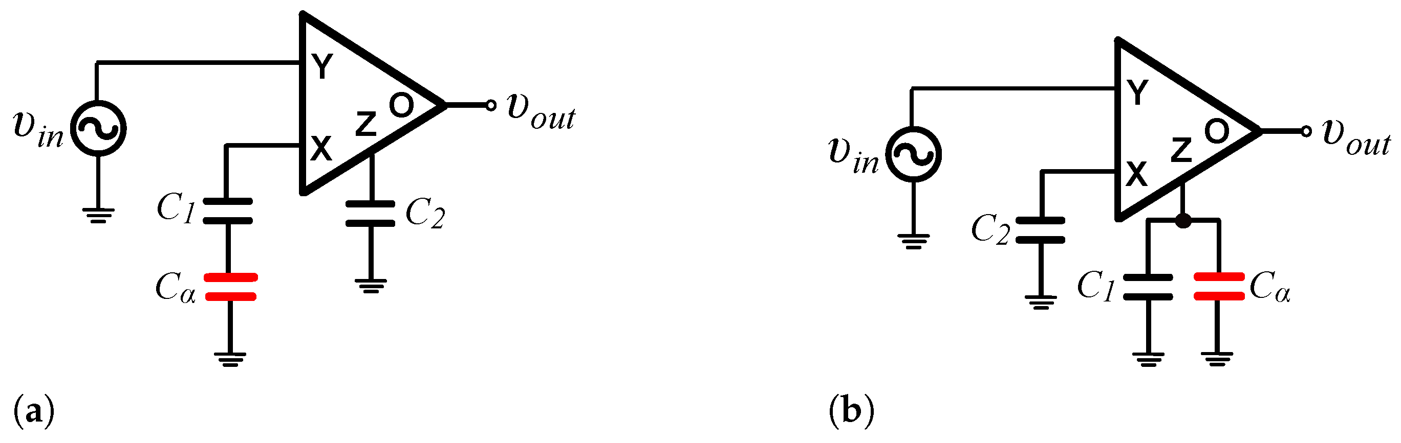
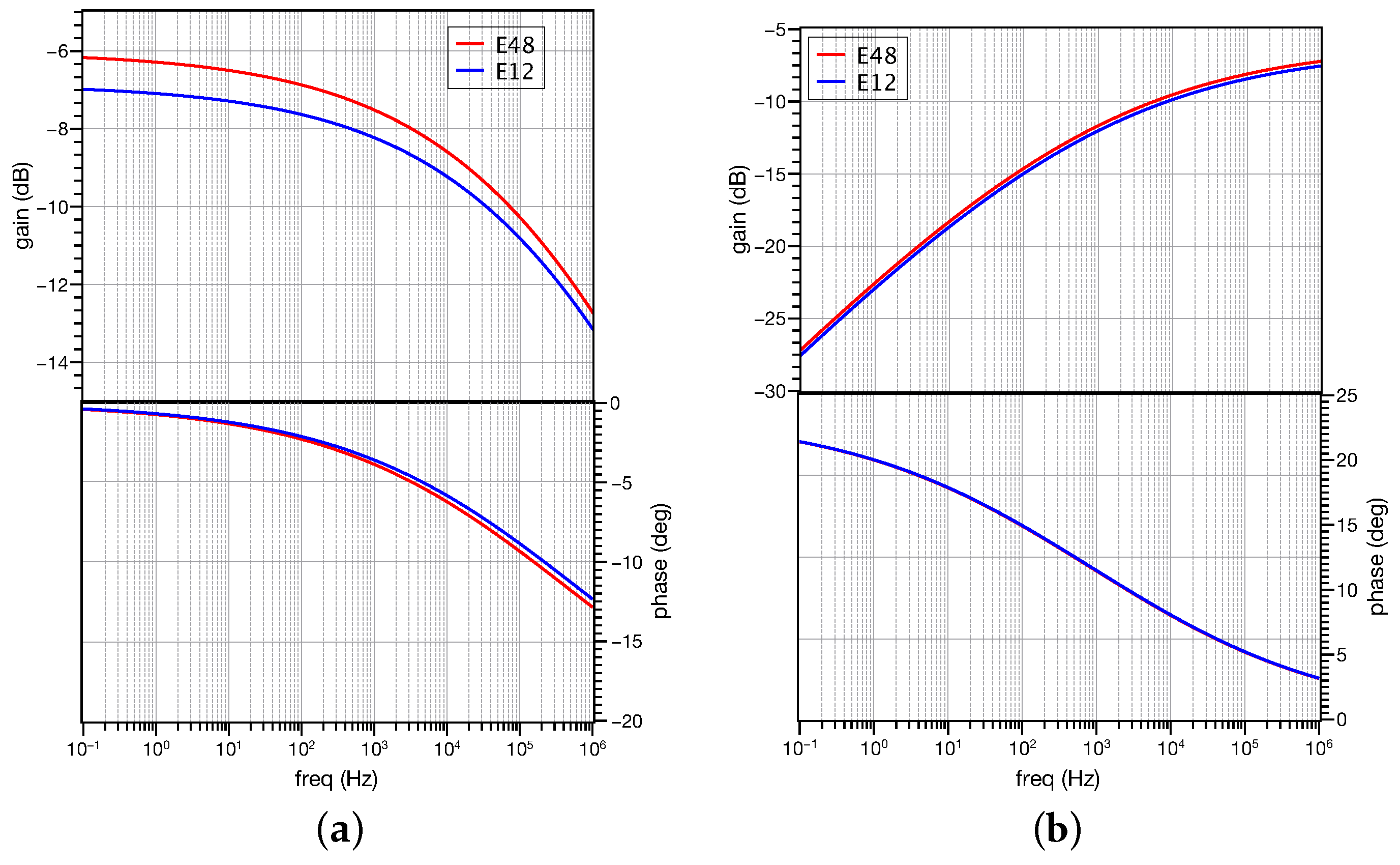
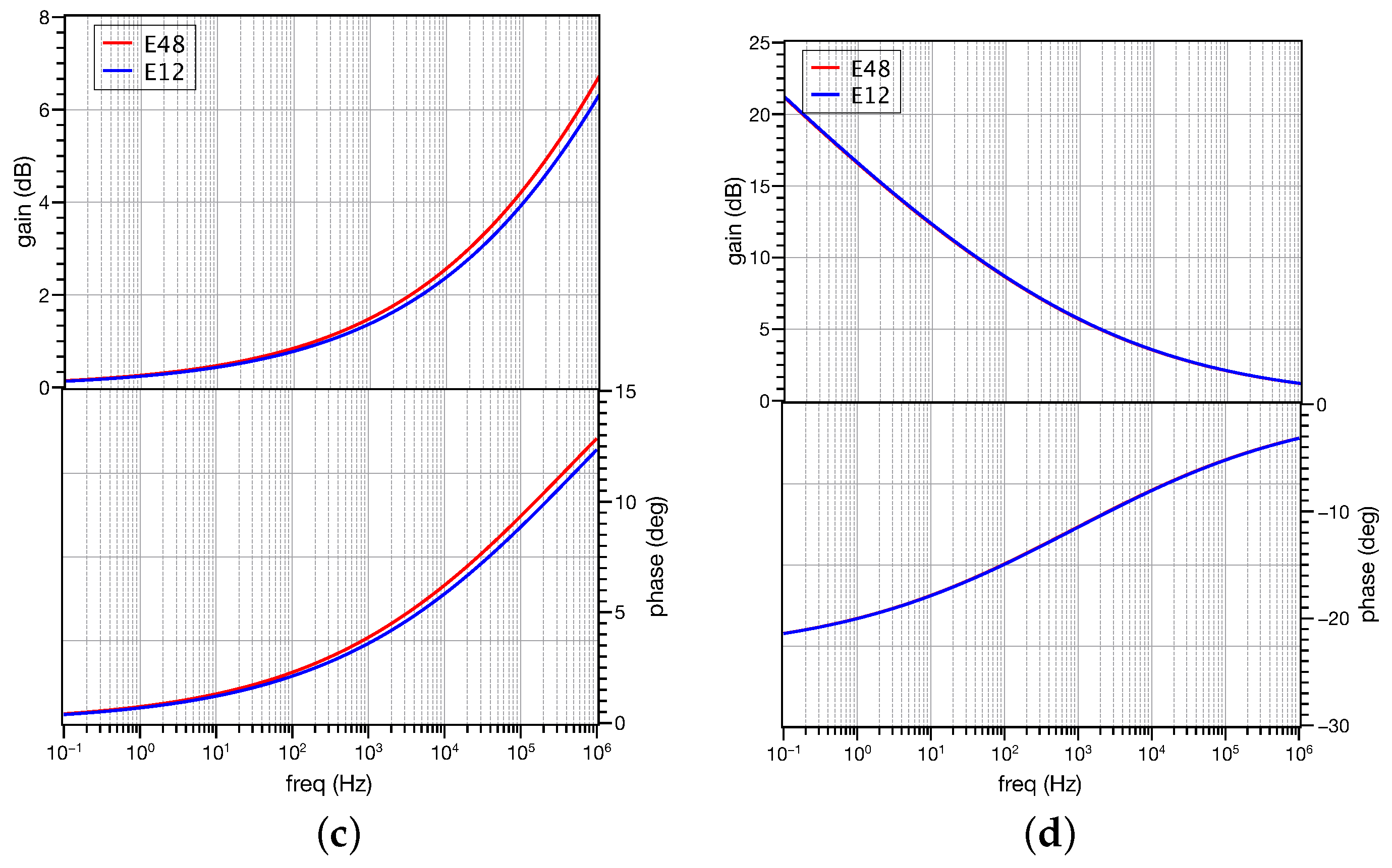
3. Filter Design Examples

3.1. Standard Filter Functions

The structures in Figure 2 will be utilized for realizing low pass and high pass filters. The resulting topologies are demonstrated in Figure 3a,b, respectively, with the realized transfer functions being
H L P ( s ) = 1 ( τ s ) 1 α + 1 ,
for the low pass filter, and
H H P ( s ) = ( τ s ) 1 α ( τ s ) 1 α + 1 ,
for the high pass filter [22]. The time constant in (9) and (10) is given by (6) and is associated with the pole frequency ( ω 0 ) according to the formula: τ = 1 / ω 0 .
The half-power frequency ( ω h ) is different from the pole frequency and is calculated according to (11)
ω h , L P = 1 τ 1 + cos 2 ( 1 α ) π 2 cos ( 1 α ) π 2 1 1 α ,
for the low pass filter, with the phase at this frequency given by (12)
H L P ( j ω ) ω = ω h , L P = tan 1 sin ( 1 α ) π 2 2 cos ( 1 α ) π 2 + 1 + cos 2 ( 1 α ) π 2 .
The corresponding expressions of the high pass filter are provided by (13) and (14)
ω h , H P = 1 τ 1 + cos 2 ( 1 α ) π 2 + cos ( 1 α ) π 2 1 1 α ,
H H P ( j ω ) ω = ω h , H P = ( 1 α ) π 2 tan 1 sin ( 1 α ) π 2 1 + cos 2 ( 1 α ) π 2 .
The filter structures in Figure 3 have both a maximum gain equal to one; in cases where a value different from one is required, the topologies in Figure 4 are suitable for this purpose.
The implemented transfer functions are the following
H L P ( s ) = C 1 C 2 · 1 ( τ s ) 1 α + 1 ,
H H P ( s ) = C 2 C 1 · ( τ s ) 1 α ( τ s ) 1 α + 1 ,
with the time constant given also by (6).

3.2. Inverse Filter Functions

Inverse filters can be used for recovering distorted signals in signal processing systems, because they have reciprocal frequency characteristics with regards to their conventional counterparts. Originated from their non-integer nature, fractional-order inverse filters offer fine adjustment of the loop shaping, performed through the adjustment of the order of the filter; also, the realized time constants can be a scaled version of those realized by their integer-order counterparts. Fractional-order inverse filters have been introduced using various types of active elements and approximating the behavior of fractional-order capacitors by suitable RC networks [23,24,25,26,27]. The approximation of inverse fractional-order filters at transfer function level has been performed in [35], resulting in topologies of increased complexity paying the price of the increased flexibility. Electronically tunable fractional-order inverse filters structures have also been introduced in [36].
Using a fractional-order capacitor, the topology in Figure 5a implements the transfer function of a fractional-order inverse low pass filter, given by (17)
H I , L P ( s ) = K · 1 + ( τ s ) 1 α ,
with K = C 2 / C 1 , and the time constant given by (6) [24].
The filter at low-frequencies has gain equal to K, while at the high-frequency range behaves as a fractional-order differentiator of order equal to 1 α .
The characteristic frequency ( ω c , I L P ), where a 3 dB increase from the minimum gain of the filter is observed, is given by (11), while the phase at this frequency is the opposite of that given in (12) [23,25,36].
The transfer function of the scheme in Figure 5b is [24]
H I , H P ( s ) = K · 1 + ( τ s ) 1 α ( τ s ) 1 α .
The filter at low frequencies behaves as integrator of order equal to 1 α , while at high frequencies has gain equal to K = C 1 / C 2 . The characteristic frequency ( ω c , I H P ), where a 3 dB drop from the maximum gain of the filter is observed, is given by (13), with the associated phase being the opposite of that in (14).

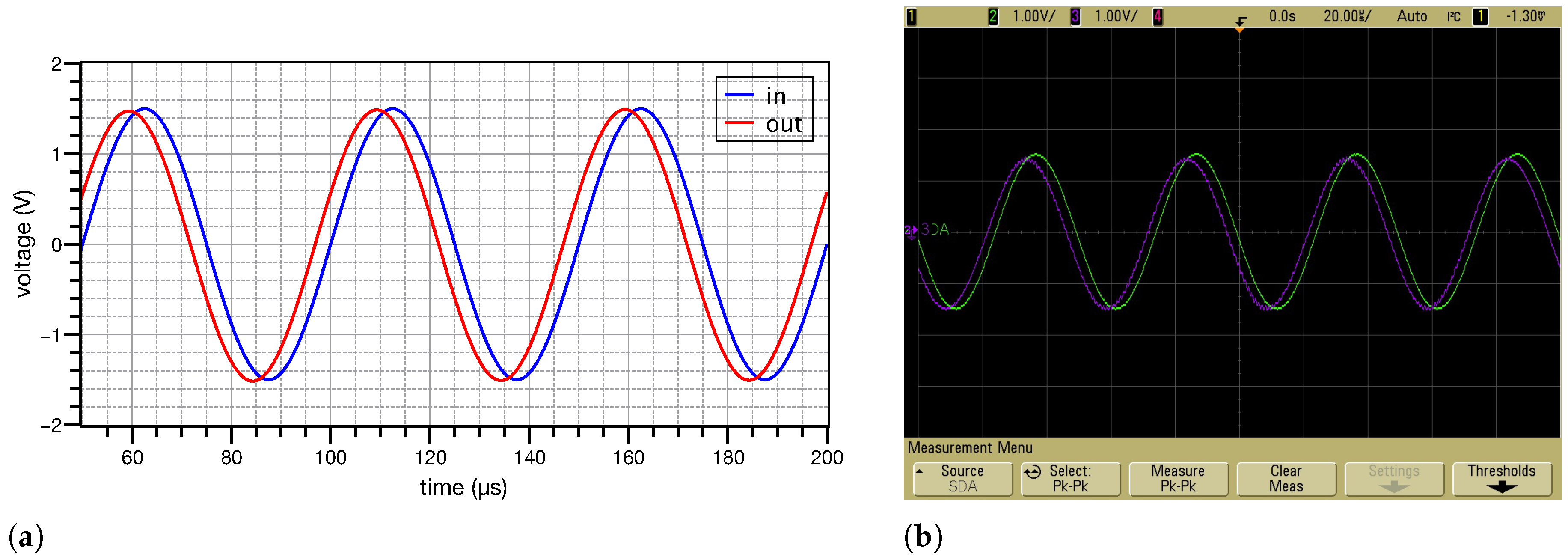
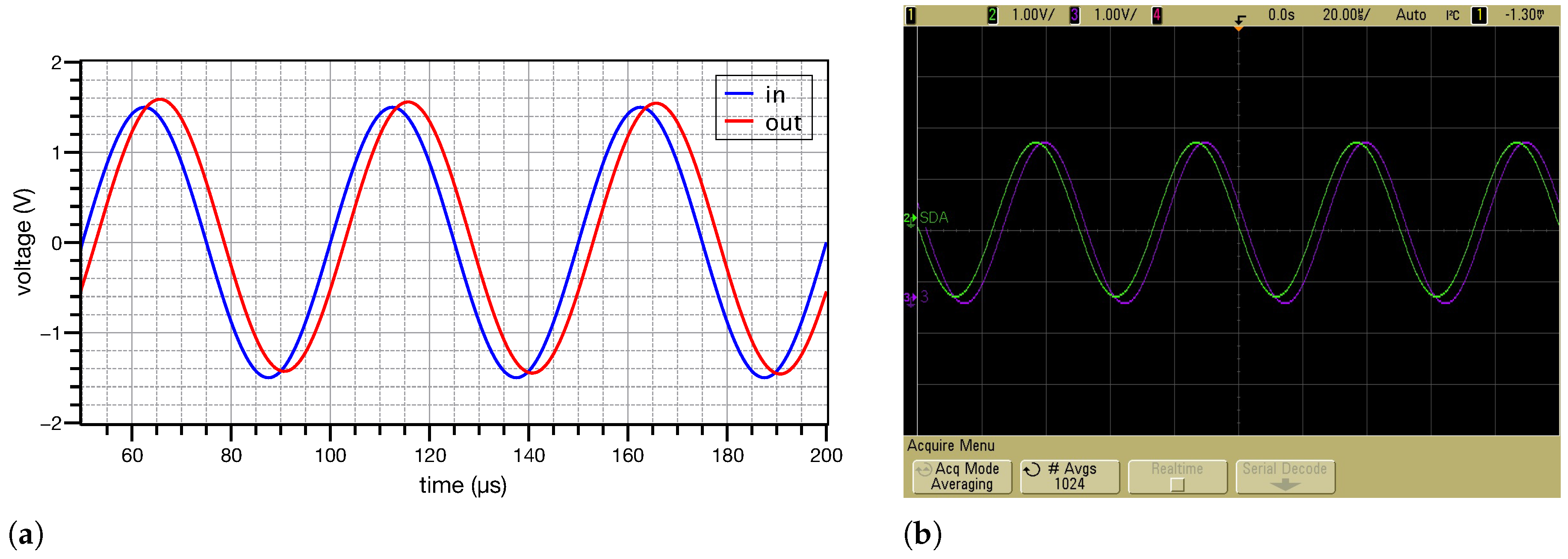
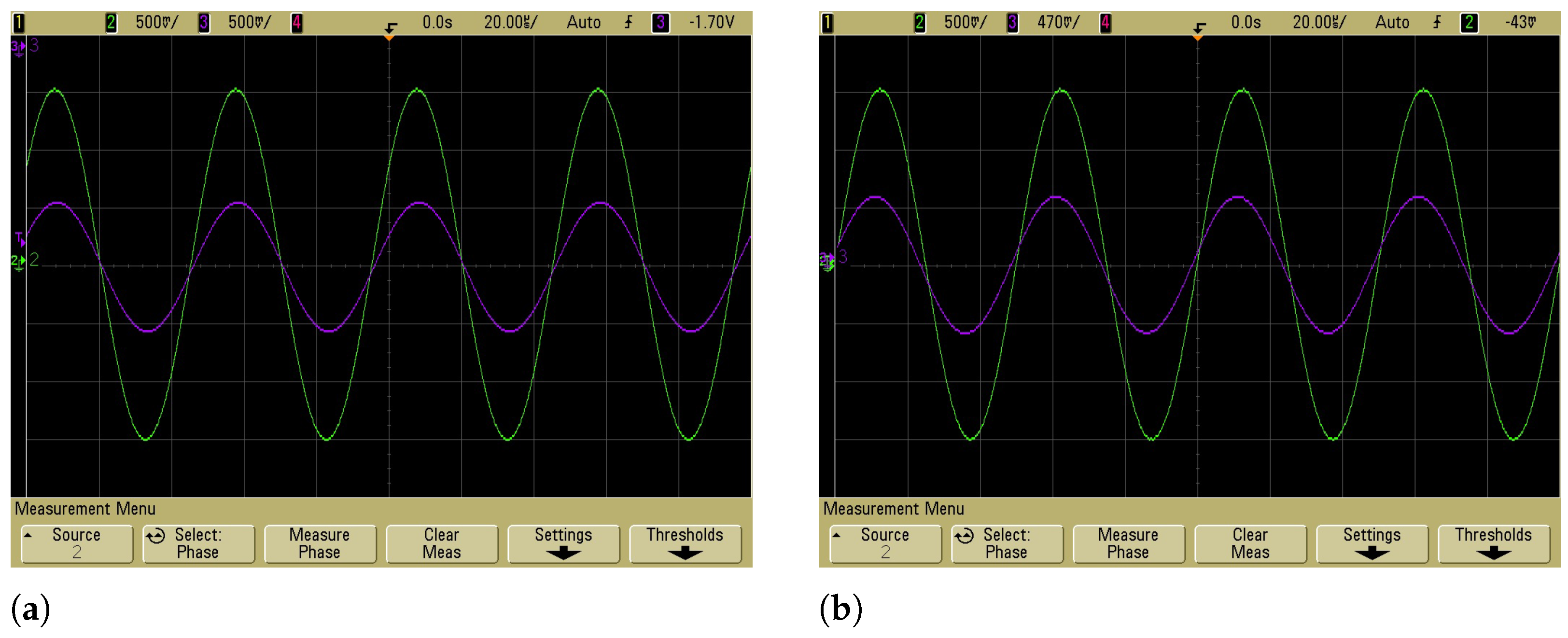
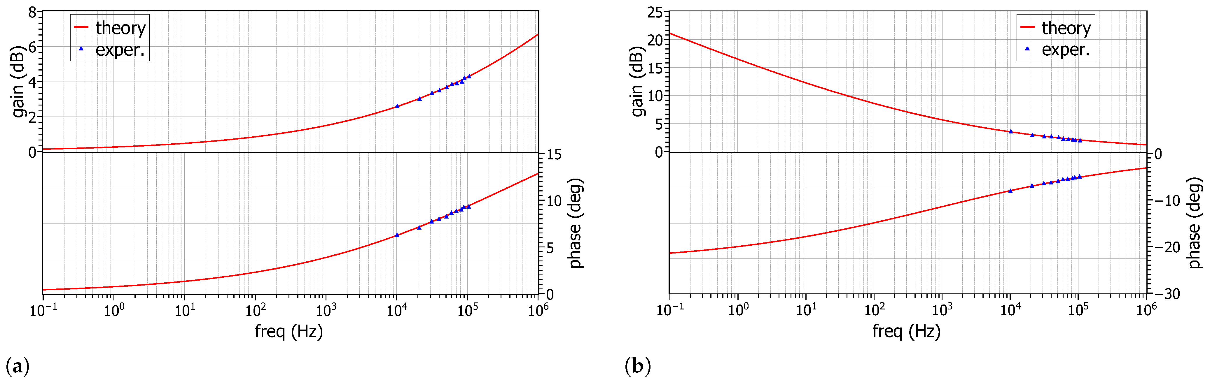
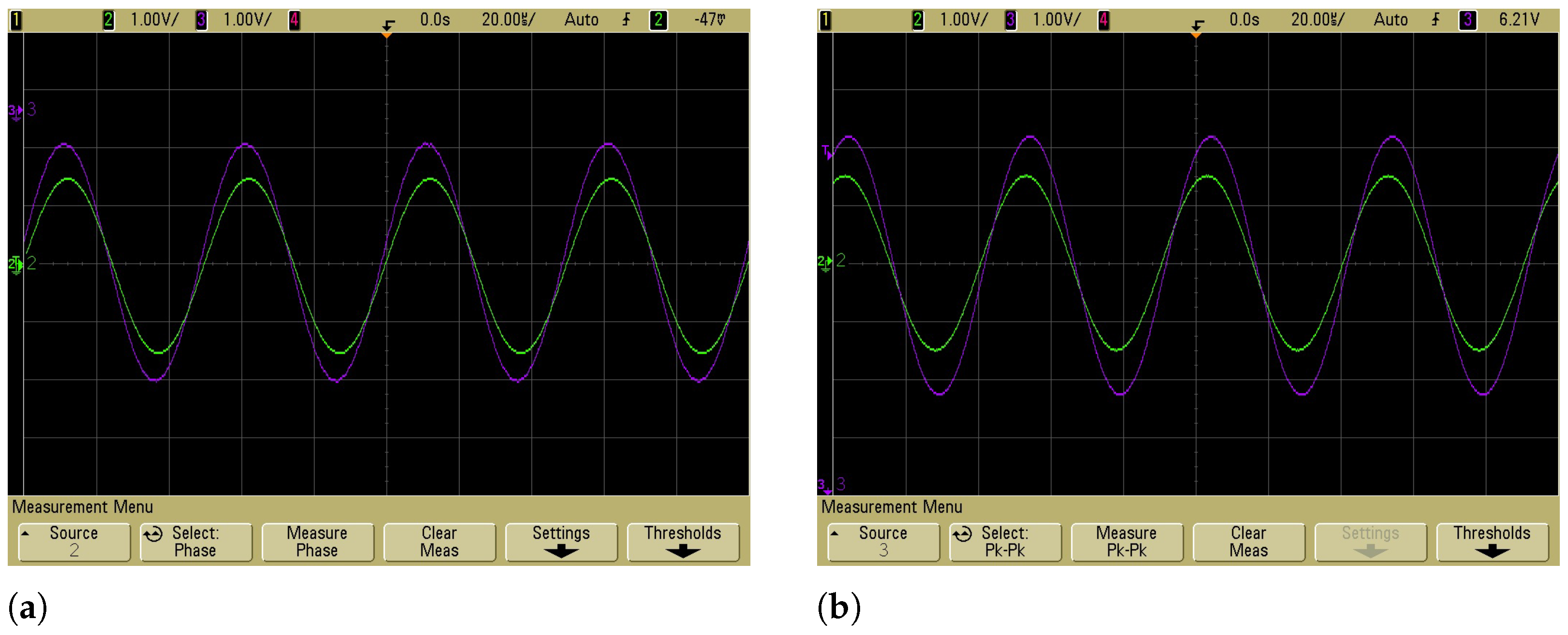
4. Experimental Results

The performance of the presented topologies has been evaluated using solid state fractional-order capacitors. They have been fabricated using multi-walled carbon nano-tubes (MWCNTs), and their order is determined by the percentage of the carbon nano-tubes (CNTs) into the epoxy resin [18]. The AD844 discrete component IC, biased at ±15 V, has been used as CFOA [37]. The experimental setup is demonstrated in Figure 6. Using a sample of fractional-order capacitor of order α = 0.74 and pseudo-capacitance C α = 5.25 nF/s0.26, which has a frequency range of operation [10 kHz, 100 kHz], the value of the integer-order capacitor, calculated through (6), for realizing a unity gain frequency equal to 20 kHz, was C 1 = 248 pF. The actual value of the capacitance, which has been used in the experiment, selected from the E48 series, was 249 pF, as it was selected from the E48 series defined in IEC 60063. The input and output waveforms in the case of the differentiator in Figure 2a stimulated by a sinusoidal of amplitude and frequency (3 Vp-p, 20 kHz), derived using the Matlab software (R2022b), are demonstrated in Figure 7a, and correspond to the theoretically predicted ones. The corresponding experimental waveforms, observed using the Agilent DSO 6034A oscilloscope, are depicted in Figure 7b. The measured gain was 1.03 and the phase difference was 22.1o, close to the theoretically predicted values 1 and 23.4o, respectively. In the case of a square wave stimulation, the corresponding plots are provided in Figure 8a,b, respectively.
The corresponding waveforms of a fractional-order integrator with the same order and unity gain frequency, stimulated by the same signals, are depicted in Figure 9a,b and Figure 10a,b. The measured values of gain was 1.02 and the phase difference was 21.4 °, close to the theoretically predicted ones that are equal to 1 and 23.4 °, respectively.
Considering the low pass filter structure in Figure 4a with half-power frequency ( f h , L P ) equal to 20 kHz and maximum gain equal to 0.5, the values of the integer-order capacitors will be C 1 = 109 pF and C 2 = 218 pF, as they are derived from (6), (11), and (15). The values of capacitors employed in experiments were 110 pF and 215 pF, respectively. In the case of the high pass filter in Figure 4b, with half-power frequency ( f h , H P ) equal to 20 kHz and maximum gain equal to 0.5, the calculated values of both integer-order capacitors through the utilization of (6), (13) and (16), were C 1 = 564 pF and C 2 = 282 pF. The actual values of capacitors employed in experiments were 562 pF and 287 pF, respectively. The obtained theoretical and experimental gain and phase frequency responses are provided in Figure 11a,b; it must be mentioned at this point that measurements in the range [10 kHz, 100 kHz] are available due to the aforementioned limited frequency range of the fractional-order capacitor. The time-domain behavior of the filters has been evaluated through the stimulation of them by a 3 V p-p sinusoidal signal and frequency equal to the half-power frequency (i.e., 20 kHz). The derived waveforms are provided in Figure 12a,b. and the measured gain and phase of the low pass filter were 0.39 and 7 °, with the corresponding theoretical values being 0.35 and 7.1 °, respectively. The corresponding results of the high pass filter were 0.37 and 8.2°, close to the theoretically predicted ones 0.35 and 7.1°. The DC power dissipation of the filters was 0.6 mW.
In the case of the inverse filters topologies in Figure 5, the same procedure as above has been followed. Considering a minimum/maximum gain equal to one and a characteristic frequency of 20 kHz for both filters, then the required integer-order capacitors will be both C 1 = C 2 = 109 pF (110 pF was the employed value) for the inverse low pass filter and C 1 = C 2 = 564 pF (562 pF the employed value) for the inverse high pass filter. The corresponding frequency and time-domain responses are depicted in Figure 13a,b and Figure 14a,b, respectively. The set of values of gain and phase, obtained from the waveforms in Figure 14a,b, are (1.39, 7.8°) and (1.48, 7.9 °), while the theoretical ones are (1.41, 7.1°) and (1.41, 7.1 °), respectively.
In order to evaluate the effect of the choice of the series of capacitor values, let us consider the case that the capacitances are chosen from the E12 series. In the obtained sets are {100 pF, 220 pF}, {560 pF, 270 pF}, {100 pF, 10 pF}, and {560 pF, 560 pF} for the low pass, high pass, inverse low pass, and inverse high pass filters, respectively. The corresponding frequency responses are provided in Figure 15a–d, with the half-power frequencies being 23.5 KHz, 19.3 kHz, 24.1 kHz, and 20.1 kHz, respectively. Taking into account that the theoretically expected value is 20 KHz, it seems that the filter topologies have reasonable sensitivity characteristics.

5. Conclusions

The resistorless structures of basic signal processing blocks in the fractional calculus domain have been experimentally tested using real fractional-order capacitors and their behavior is in excellent agreement with the theory. The proposed concept is independent of the type of the fractional capacitor used, as well as the type of active elements, making it suitable for large-signal operation. Limitations are imposed by the frequency range of operation and by the linearity of the samples of fractional-order capacitors, both determined by the fabrication process used for their implementation, and by the employed active elements. This technique is also particularly promising for implementing systems suitable for low-frequency applications, including control, biology/bio-medicine applications due to the nature of the formed time-constants expressions. Further research steps include the comparison of the performance of the proposed structures with the corresponding switched-capacitor fractional-order stages, which are another type of large-signal-based resistorless implementation of fractional-order filters [38].

Author Contributions

Conceptualization, C.P., P.B. and A.S.E.; methodology, D.P., P.B. and C.P.; software, D.P. and G.T.; validation, D.P. and G.T.; formal analysis, D.P.; investigation, D.P.; writing—original draft preparation, D.P., P.B. and C.P.; writing—review and editing, C.P. and A.S.E.; project administration, C.P. and A.S.E. All authors have read and agreed to the published version of the manuscript.

Funding

This research received no external funding.

Data Availability Statement

No new data were created or analyzed in this study. Data sharing is not applicable to this article.

Conflicts of Interest

The authors declare no conflict of interest.

Abbreviations

The following abbreviations are used in this manuscript:
CFOACurrent Feedback Operational Amplifier
CNTCarbon Nano-Tubes
MWCNTMulti-Walled Carbon Nano-Tubes
RCResistor Capacitor

References

  1. Podlubny, I. Fractional-order systems and PIλDμ controllers. IEEE Trans. Autom. Control 1999, 44, 208–214. [Google Scholar] [CrossRef]
  2. Gómez-Aguilar, J.; Yépez-Martínez, H.; Escobar-Jiménez, R.; Astorga-Zaragoza, C.; Reyes-Reyes, J. Analytical and numerical solutions of electrical circuits described by fractional derivatives. Appl. Math. Model. 2016, 40, 9079–9094. [Google Scholar] [CrossRef]
  3. Biswas, K.; Bohannan, G.; Caponetto, R.; Lopes, A.M.; Machado, J.A.T. Fractional-Order Devices; Springer: Berlin/Heidelberg, Germany, 2017. [Google Scholar]
  4. Freeborn, T.J. A survey of fractional-order circuit models for biology and biomedicine. IEEE J. Emerg. Sel. Top. Crcuits Syst. 2013, 3, 416–424. [Google Scholar] [CrossRef]
  5. Tsirimokou, G.; Psychalinos, C.; Elwakil, A. Design of CMOS Analog Integrated Fractional-Order Circuits: Applications in Medicine And Biology; Springer: Berlin/Heidelberg, Germany, 2017. [Google Scholar]
  6. Said, L.A.; Radwan, A.G.; Madian, A.H.; Soliman, A.M. Three fractional-order-capacitors-based oscillators with controllable phase and frequency. J. Circ. Syst. Comput. 2017, 26, 1750160. [Google Scholar] [CrossRef] [Green Version]
  7. Domansky, O.; Sotner, R.; Langhammer, L.; Jerabek, J.; Psychalinos, C.; Tsirimokou, G. Practical design of RC approximants of constant phase elements and their implementation in fractional-order PID regulators using CMOS Voltage Differencing Current Conveyors. Circ. Syst. Signal Process. 2019, 38, 1520–1546. [Google Scholar] [CrossRef]
  8. Tlelo-Cuautle, E.; Pano-Azucena, A.D.; Guillén-Fernández, O.; Silva-Juárez, A. Analog Implementations of Fractional-Order Chaotic Systems. In Analog/Digital Implementation of Fractional Order Chaotic Circuits and Applications; Springer: Berlin/Heidelberg, Germany, 2020; pp. 93–114. [Google Scholar]
  9. Tepljakov, A.; Alagoz, B.B.; Yeroglu, C.; Gonzalez, E.A.; Hosseinnia, S.H.; Petlenkov, E.; Ates, A.; Cech, M. Towards Industrialization of FOPID Controllers: A Survey on Milestones of Fractional-Order Control and Pathways for Future Developments. IEEE Access 2021, 9, 21016–21042. [Google Scholar] [CrossRef]
  10. Yousri, D.; AbdelAty, A.M.; Said, L.A.; AboBakr, A.; Radwan, A.G. Biological inspired optimization algorithms for cole-impedance parameters identification. AEU-Int. J. Electron. Commun. 2017, 78, 79–89. [Google Scholar] [CrossRef]
  11. Khalil, N.A.; Mohsen, M.; Ahmed, G.M.; Said, L.A.; Madian, A.H.; Radwan, A.G. Chapter Ten - Fractional-order oscillators based on a single Op-Amp. In Fractional Order Systems; Emerging Methodologies and Applications in Modelling; Radwan, A.G., Khanday, F.A., Said, L.A., Eds.; Academic Press: Cambridge, MA, USA, 2022; Volume 1, pp. 411–439. [Google Scholar] [CrossRef]
  12. Bertsias, P.; Psychalinos, C.; Elwakil, A.S.; Biswas, K. Single transistor fractional-order filter using a multi-walled carbon nanotube device. Analog. Integr. Circ. Signal Process. 2019, 100, 215–219. [Google Scholar] [CrossRef]
  13. Biswas, K.; Sen, S.; Dutta, P.K. Realization of a constant phase element and its performance study in a differentiator circuit. IEEE Trans. Circ. Syst. II Express Briefs 2006, 53, 802–806. [Google Scholar] [CrossRef]
  14. Biswas, K.; Caponetto, R.; Di Pasquale, G.; Graziani, S.; Pollicino, A.; Murgano, E. Realization and characterization of carbon black based fractional order element. Microelectron. J. 2018, 82, 22–28. [Google Scholar] [CrossRef]
  15. Buscarino, A.; Caponetto, R.; Di Pasquale, G.; Fortuna, L.; Graziani, S.; Pollicino, A. Carbon black based capacitive fractional order element towards a new electronic device. AEU-Int. J. Electron. Commun. 2018, 84, 307–312. [Google Scholar] [CrossRef]
  16. Buscarino, A.; Caponetto, R.; Graziani, S.; Murgano, E. Realization of fractional order circuits by a Constant Phase Element. Eur. J. Control 2020, 54, 64–72. [Google Scholar] [CrossRef]
  17. Caponetto, R.; Di Pasquale, G.; Graziani, S.; Murgano, E.; Pollicino, A. Realization of green fractional order devices by using bacterial cellulose. AEU-Int. J. Electron. Commun. 2019, 112, 152927. [Google Scholar] [CrossRef]
  18. John, D.A.; Banerjee, S.; Bohannan, G.W.; Biswas, K. Solid-state fractional capacitor using MWCNT-epoxy nanocomposite. Appl. Phys. Lett. 2017, 110, 163504. [Google Scholar] [CrossRef]
  19. John, D.A.; Aware, M.V.; Junghare, A.S.; Biswas, K. Performance Analysis of Solid-State Fractional Capacitor-Based Analog PIλDμ Controller. Circ. Syst. Signal Process. 2020, 39, 1815–1830. [Google Scholar] [CrossRef]
  20. Mohapatra, A.S.; Sarkar, S.; Biswas, K. Fabricating Solid State Fractional Capacitor in the Frequency Range of mHz to kHz. IEEE Trans. Comp. Packag. Manuf. Technol. 2021, 11, 2035–2038. [Google Scholar] [CrossRef]
  21. Tsirimokou, G.; Kartci, A.; Koton, J.; Herencsar, N.; Psychalinos, C. Comparative study of discrete component realizations of fractional-order capacitor and inductor active emulators. J. Circ. Syst. Comput. 2018, 27, 1850170. [Google Scholar] [CrossRef]
  22. Radwan, A.G.; Soliman, A.M.; Elwakil, A.S. First-order filters generalized to the fractional domain. J. Circ. Syst. Comput. 2008, 17, 55–66. [Google Scholar] [CrossRef]
  23. Bhaskar, D.; Kumar, M.; Kumar, P. Fractional order inverse filters using operational amplifier. Analog. Integr. Circ. Signal Process. 2018, 97, 149–158. [Google Scholar] [CrossRef]
  24. Bhaskar, D.; Kumar, M.; Kumar, P. Minimal realization of fractional-order inverse filters. IETE J. Res. 2020, 1–14. [Google Scholar] [CrossRef]
  25. Hamed, E.M.; Said, L.A.; Madian, A.H.; Radwan, A.G. On the approximations of CFOA-based fractional-order inverse filters. Circ. Syst. Signal Process. 2020, 39, 2–29. [Google Scholar] [CrossRef]
  26. Khali, N.A.; Said, L.A.; Radwan, A.G.; Soliman, A.M. Multifunction fractional inverse filter based on OTRA. In Proceedings of the 2019 Novel Intelligent and Leading Emerging Sciences Conference (NILES), Giza, Egypt, 28–30 October 2019; IEEE: Piscataway, NJ, USA, 2019; Volume 1, pp. 162–165. [Google Scholar] [CrossRef]
  27. Kumar, M.; Bhaskar, D.; Kumar, P. CFOA-Based New Structure of Fractional Order Inverse Filters. Int. J. Recent Technol. Eng 2020, 8, 2277–3878. [Google Scholar] [CrossRef]
  28. Matsuda, K.; Fujii, H. H optimized wave-absorbing control-Analytical and experimental results. J. Guid. Control Dyn. 1993, 16, 1146–1153. [Google Scholar] [CrossRef]
  29. Oustaloup, A.; Levron, F.; Mathieu, B.; Nanot, F.M. Frequency-band complex noninteger differentiator: Characterization and synthesis. IEEE Trans. Circ. Syst. I Fund. Theory Appl. 2000, 47, 25–39. [Google Scholar] [CrossRef]
  30. Charef, A. Analogue realisation of fractional-order integrator, differentiator and fractional PIλDμ controller. IEE Proc.-Control Theory Appl. 2006, 153, 714–720. [Google Scholar] [CrossRef]
  31. Krishna, M.S.; Das, S.; Biswas, K.; Goswami, B. Fabrication of a fractional order capacitor with desired specifications: A study on process identification and characterization. IEEE Trans. Electron Devices 2011, 58, 4067–4073. [Google Scholar] [CrossRef]
  32. Bertsias, P.; Psychalinos, C.; Maundy, B.J.; Elwakil, A.S.; Radwan, A.G. Partial fraction expansion–based realizations of fractional-order differentiators and integrators using active filters. Int. J. Circuit Theory Appl. 2019, 47, 513–531. [Google Scholar] [CrossRef]
  33. Tsirimokou, G.; Psychalinos, C.; Elwakil, A.S.; Salama, K.N. Electronically tunable fully integrated fractional-order resonator. IEEE Trans. Circuits Syst. II Express Briefs 2017, 65, 166–170. [Google Scholar] [CrossRef]
  34. Jerabek, J.; Sotner, R.; Dvorak, J.; Polak, J.; Kubanek, D.; Herencsar, N.; Koton, J. Reconfigurable fractional-order filter with electronically controllable slope of attenuation, pole frequency and type of approximation. J. Circ. Syst. Comput. 2017, 26, 1750157. [Google Scholar] [CrossRef] [Green Version]
  35. Mahata, S.; Herencsar, N.; Kubanek, D. Further Generalization and Approximation of Fractional-Order Filters and Their Inverse Functions of the Second-Order Limiting Form. Fractal Fract. 2022, 6, 209. [Google Scholar] [CrossRef]
  36. Bertsias, P.; Tsirimokou, G.; Psychalinos, C.; Elwakil, A. Fully electronically tunable inverse fractional-order filter designs. In Proceedings of the 2019 Novel Intelligent and Leading Emerging Sciences Conference (NILES), Giza, Egypt, 28–30 October 2019; IEEE: Piscataway, NJ, USA, 2019; Volume 1, pp. 42–45. [Google Scholar]
  37. Analog Devices. AD844: Monolithic Op Amp with Quad Low Noise. Data Retrieved from Analog Devices. Available online: https://www.analog.com/media/en/technical-documentation/data-sheets/AD844.pdf (accessed on 19 November 2022).
  38. Psychalinos, C.; Elwakil, A.; Maundy, B.; Allagui, A. Analysis and realization of a switched fractional-order-capacitor integrator. Int. J. Circuit Theory Appl. 2016, 44, 2035–2040. [Google Scholar] [CrossRef]
Figure 1. CFOA-based implementations of fractional-order (a) differentiator, and (b) integrator.
Electronics 11 03988 g001
Figure 2. Proposed resistorless implementations of fractional-order (a) differentiator, and (b) integrator.
Electronics 11 03988 g002
Figure 3. Implementations of fractional-order (a) low pass and (b) high pass filters using the structures in Figure 2.
Electronics 11 03988 g003
Figure 4. Implementations of fractional-order (a) low pass and (b) high pass filters with variable maximum gain.
Electronics 11 03988 g004
Figure 5. Implementations of fractional-order inverse (a) low pass, and (b) high pass filters.
Electronics 11 03988 g005
Figure 6. Experimental setup for evaluating the performance of the proposed filters.
Electronics 11 03988 g006
Figure 7. Input and output waveforms of a fractional-order differentiator of order 0.26, realized by the topology in Figure 2a, for a sinusoidal (3Vp-p, 20 kHz) stimulus (a)theoretical, and (b)experimental.
Electronics 11 03988 g007
Figure 8. Input and output waveforms of a fractional-order differentiator of order 0.26, realized by the topology in Figure 2a, for a square wave (3 Vp-p, 20 kHz) stimulus (a)theoretical and (b) experimental.
Electronics 11 03988 g008
Figure 9. Input and output waveforms of a fractional-order integrator of order 0.26, realized by the topology in Figure 2b, for a sinusoidal (3 Vp-p, 20 kHz) stimulus (a)theoretical, and (b) experimental.
Electronics 11 03988 g009
Figure 10. Input and output waveforms of a fractional-order integrator of order 0.26, realized by the topology in Figure 2b, for a square wave (3 Vp-p, 20 kHz) stimulus (a)theoretical, and (b) experimental.
Electronics 11 03988 g010
Figure 11. Frequency responses of filters of order 0.26, realized by (a)the topology in Figure 4a, and (b)the topology in Figure 4b.
Electronics 11 03988 g011
Figure 12. Input and output waveforms of filters of order 0.26, realized by (a) the topology in Figure 4a, and (b) the topology in Figure 4b, stimulated by a (3 Vp-p, 20 kHz) sinusoidal input.
Electronics 11 03988 g012
Figure 13. Frequency responses of inverse filters of order 0.26, realized by (a)the topology in Figure 5a, and (b)the topology in Figure 5b.
Electronics 11 03988 g013
Figure 14. Input and output waveforms of inverse filters of order 0.26, realized by (a) the topology in Figure 5a, and (b) the topology in Figure 5b stimulated by a (3 Vp-p, 20 kHz) sinusoidal input.
Electronics 11 03988 g014
Figure 15. Evaluation of the effect of the error in the capacitors values on the frequency response of the (a)low pass, (b)high pass, (c)inverse low pass, and (d)inverse high pass filters.
Electronics 11 03988 g015aElectronics 11 03988 g015b
Table 1. Passive elements of a Foster-I network for approximating a fractional-order capacitor with pseudo-capacitance C α =1 μF and order α = 0.8 .
ElementValueElementValue
R p 100 Ω --
R 1 348 Ω C 1 332 nF
R 2 3.48 k Ω C 1 562 nF
R 3 31.6 k Ω C 1 953 nF
R 4 301 k Ω C 1 1.62 μF
R 5 5.9 M Ω C 1 1.27 μF
Table 2. Passive elements of a Foster-I network for approximating a fractional-order capacitor with pseudo-capacitance C α =1 μF and order α = 0.2 .
ElementValueElementValue
R p 100 k Ω --
R 1 71.5 Ω C 1 0.75 nF
R 2 127 k Ω C 1 6.81 nF
R 3 215 k Ω C 1 61.9 nF
R 4 383 k Ω C 1 562 nF
R 5 681 k Ω C 1 4.87 μF
Publisher’s Note: MDPI stays neutral with regard to jurisdictional claims in published maps and institutional affiliations.

