Article

Experimental Validation and Applications of mm-Wave 8 × 8 Antenna-in-Package (AiP) Array Platform

Antenna Propagation and Millimeter-Wave Systems (APMS) Section, Department of Electronic Systems, Faculty of Engineering and Science, Aalborg University, 9220 Aalborg, Denmark
*
Author to whom correspondence should be addressed.
Electronics 2022, 11(23), 4055; https://doi.org/10.3390/electronics11234055
Submission received: 3 November 2022 / Revised: 28 November 2022 / Accepted: 29 November 2022 / Published: 6 December 2022
(This article belongs to the Special Issue Massive MIMO Technology for 5G and Beyond)

Abstract

:
Phased array antennas play an indispensable role in millimeter-wave (mmWave) communications. The Antenna-in-package (AiP) system combines advanced antenna and packaging technology, making it highly valuable for various cellular, radar and automative applications. The benefits it brings in terms of small size, low development costs, low power consumption and fast beam-steering capability further drive the vast deployment of phased array antennas in mmWave systems. In this paper, an 8 × 8 AiP experimental platform is presented and its operating performance is measured and analyzed. Further, two application examples of the AiP are presented, namely, a platform for investigating the phased array calibration performance of different methods, and an AiP-based channel sounder for channel characterization. The performance of the channel sounder is verified by analysing the angle of arrival (AoA), angle of departure (AoD) and propagation delay of the measured dominant propagation components (DPCs).

1. Introduction

With the exponential growth of wireless data transmission applications in various scenarios, 5G communications at mmWaves frequency bands provide new valuable radio spectrum for wireless communications [1,2,3]. The large available bandwidth of mmWaves communications can greatly increase the speed of wireless data transmission in numerous applications [4,5,6]. Notably, not only has the US Federal Communications Commission (FCC) released considerable available spectrum in the 28–73 GHz band but also the bands available in the future are being reviewed [7,8,9]. Hence, mmWave has great promise for research and application. However, the high propagation loss and the low signal-to-noise ration (SNR) at mmWave frequencies have limited the rapid expansion of mmWave communications to a considerable extent [10,11].
In order to overcome the above mentioned drawbacks of mmWave and to increase the range of mmWave radio transmission, directional high gain antennas are widely used as system transmitter (Tx) or receiver (Rx) in communication systems [12,13,14]. However, as the gain of the antenna increases, the beam-width of the antenna decreases, which reduces the effective coverage of the antenna. To ensure reliable communication in dynamic scenarios where locations of Tx/Rx and propagation scenarios are time-variant, beam-tracking is of critical importance. Furthermore, electrical beam-steering of phased arrays is essential to support real-time tracking of the dominant propagation paths [15,16,17]. Phased array systems are widely used in mmWave systems, where each radio frequency chain consists of an antenna, a phase shifter and an attenuator [18]. The phase and amplitude excitation of each element can be designed with the help of the phase shifters and attenuators so that the phased array beam pattern can be steered to given spatial directions.
AiP system combines all the antennas and control circuits of a phased array system into a single package. This allows for low development and maintenance costs, fast product iterations, easy installation and portability, and low operational energy consumption. AiP technology has been widely used in mmWave, for instance, radios, automotive radars, imaging sensors [19,20,21]. In this paper, the main hardware and control architecture of an 8 × 8 AiP which is extended based on the 4 × 4 AiP design architecture presented in [22] are introduced. A series of experiments are conducted to verify the AiP stability and evaluate the accuracy of elemental composite weight control, before the application of the AiP. Further, two application examples of the AiP are presented, where the AiP is used as an experimental platform for phased array calibration and mmWave channel sounding, respectively, as detailed below:
Beamforming of a phased array system is achieved by properly setting the complex weight for each element. Therefore it is crucial to calibrate out the initial excitations of array elements to guarantee the beamforming performance. Different calibration methods have been proposed in the literature, aminly for sub-6 GHz frequency bands [23,24,25,26]. In this work, we aim to investigate how well the calibration method works in practical mmWave phased arrays. More specifically, we would like to investigate (1) how stable the AiP works (2) how temperature of the AiP affects the array calibration accuracy (3) to which extend the calibration can help improve the beamforming performance and (4) how accurate array calibration the different calibration methods can achieve in practical mmWave AiPs.
In addition, it is worth noting that channel measurement and characterization are essential for wireless system development, and much work is actively being done on mmWave channel sounding [27,28,29,30]. The state-of-art channel sounder systems, either mechanically rotating a directional antenna (typically a horn antenna) [31] or an omni-directional antenna to form a virtual array [32], suffer from long measuring time. The phased array can be employed in the channel sounder, where the electronically driven beamforming function will enable the channel sounder to reduce the channel measurement time considerably. To shorten the channel measurement time, the replacement of the conventional static antenna on the Tx/Rx of the channel sounder with a phased array is gradually being proposed and the associated measurements are being presented. In [33] a 28.5 GHz channel sounder with 8 × 8 phased arrays at the Tx and Rx is proposed. The channel sounder sweep time for a 3-D double-omnidirectional dual-polarized channel is just 1.3 ms. In [34] an mmWave channel sounder that covers 360 degrees and 60 degrees in azimuth and elevation, respectively, with a sweep time of 6.25 ms is presented. The sounder also can be applied to dynamic channel measurements. In [35] the high resolution phased array radar system detection range can reach up to 250 m with 28 GHz 5G communications. Due to highly integrated AiP system design, it has only few external interfaces, which makes the channel sounder easier to implement and more efficient to set up than a channel sounder system using other type of phased arrays. The small size, low-weight and low energy consumption of the AiP also make it easy to carry and move around. This will make it more favorable in measurement scenarios where channel sounder Tx/Rx requires motion.
In this paper, we apply the AiP system to channel sounding and propose a 26.5–29.5 GHz channel sounder with the 8 × 8 AiP and a 4 × 4 AiP employed as the Rx and the Tx, respectively. In addition, the effectiveness of different calibration methods for large arrays, and the effect of measurement noise on accuracy of different calibration methods have been investigated based on the AiP system. Practical channel measurements are carried out with the AiP system and the results are analysed. The rest of the paper is structured as follows. First, the 8 × 8 AiP experimental platform is presented and the AiP operating performance is verified in Section 2. Section 3 describes the applications of AiP in verification of the accuracy for calibration method and in channel sounding, the corresponding measurements are carried out and the results are analyzed. Finally, Section 4 concludes the paper.

2. Mmwave 8 × 8 AiP Array Platform

In this section, we introduce the main hardware and control architecture of the 8 × 8 AiP. In order to verify the stability and beamforming performance of the AiP, corresponding measurements are carried out.

2.1. Aip Array Platform Presentation

As mentioned in the introduction, the mmWave 8 × 8 AiP array platform is based on the architecture of the 4 × 4 AiP array platform presented in [22]. The photograph and antennas layout of the 8 × 8 AiP array module are shown in Figure 1a,b, respectively. The 64 element antennas of the AiP array are arranged in the form of an 8 × 8 square. The spacing between the antennas elements is 4.6 mm, which is approximately equal to a half-wavelength (that is 4.67 mm) for 28 GHz. The block diagram of the 8 × 8 AiP illustrated in Figure 2, which is adapted from [22]. The 8 × 8 AiP consists of:
(a)
64 patch antennas operating at 26.5 to 29.5 GHz.
(b)
64 6-bit phase shifters with a phase shift range of 0° to 359°, and a control resolution of 5.625 ° .
(c)
64 6-bit attenuators with an attenuation range of 0 to 7.5 dB, and a control resolution of 0.5 dB.
(d)
32 common attenuators with an attenuation range of 0 to 15 dB, and a control resolution of 1 dB.
(e)
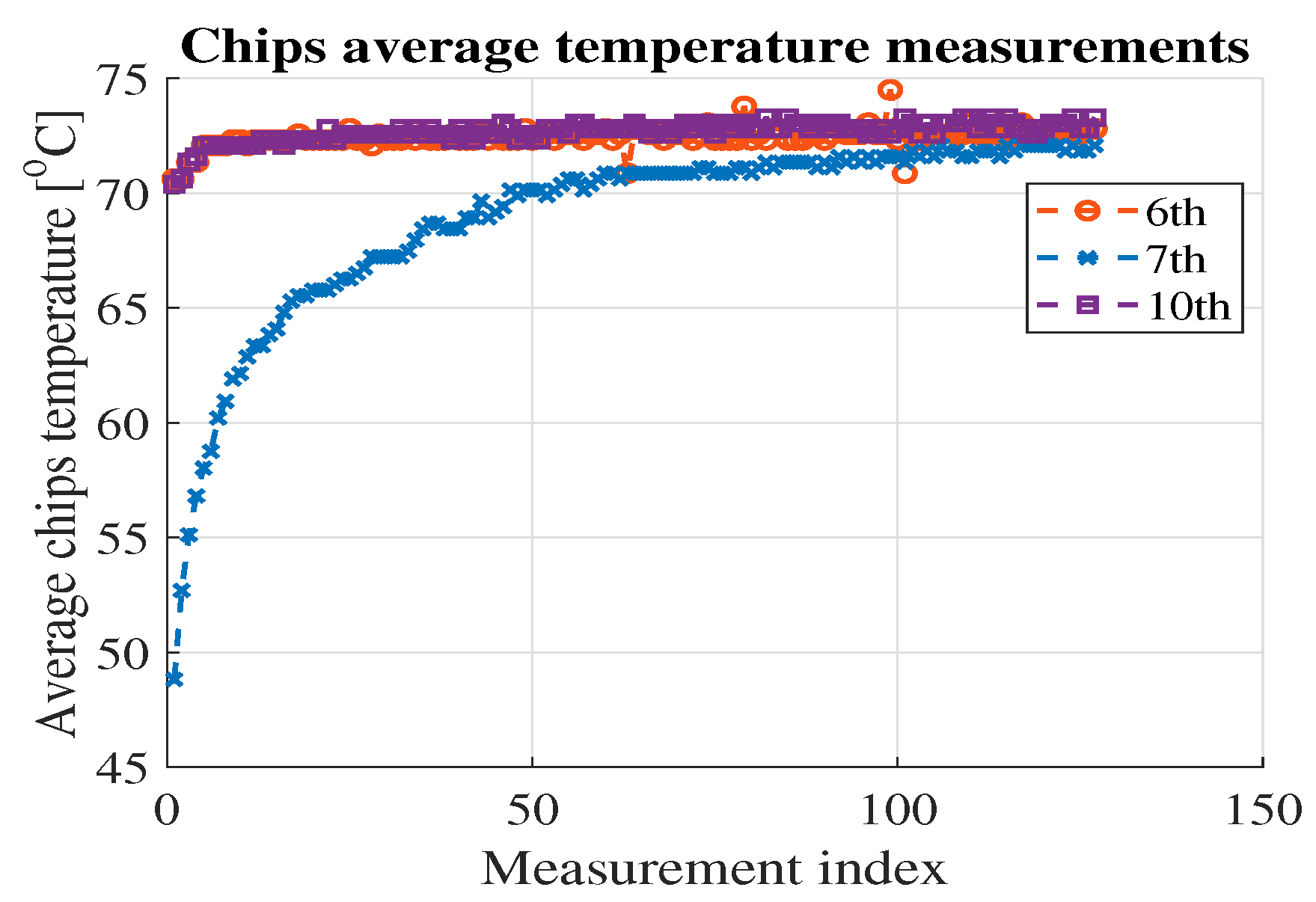
32 temperature variable attenuators (TVAs), which provide gain compensation for the disturbance of RF chains due to the variation of the AiP temperature.
(f)
64 power amplifiers (PAs), which are tuned when the AiP is in Tx mode, and 64 low noise amplifiers (LNAs), which are tuned with the AiP in Rx mode.
(g)
160 switches, which are swithed to set the operating mode (i.e., Tx or Rx) of the AiP.
(h)
16 ANOKIAWAVE AWMF-0158 RFICs chips. Each RFIC on the AiP board has four control chains, each of which is connected to a patch antenna. A 6-bit phase shifter and a 6-bit attenuator are integrated in each control chain for the phase and amplitude control, respectively. Therefore, the excitation of the patch antenna is fed by controlling the phase shifter and attenuator in the RFIC.
(i)
One STM32F427VIT6 chip acts as the microprogrammed control unit (MCU) of the AiP board. The MCU interacts with the external control computer via a universal asynchronous receiver/transmitter (UART). The control of the AiP RFICs chips by the MCU, is achieved via the serial peripheral interphase (SPI).
Based on the hardware platform, the main program of the designed AiP includes the commands to control the aforementioned element phase shifters, common attenuators and element attenuators, and also the following commands:
(a)
Tx/Rx mode switching command for setting the AiP to work in Tx or Rx mode, respectively.
(b)
Element switch command for controlling each element of the AiP to turn on or off.
(c)
Chip temperature read command for reading the temperature of each chip of the AiP.

2.2. Aip Array Platform Experimental Validation

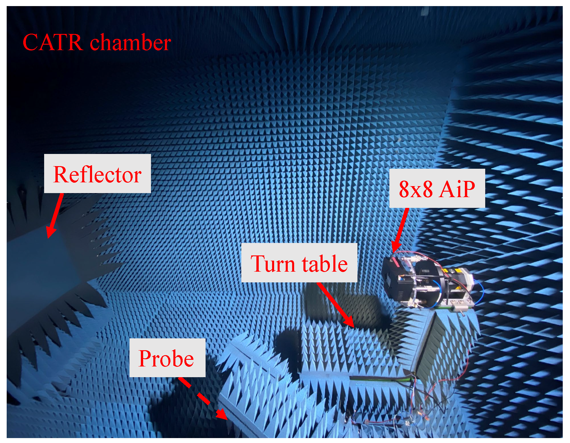
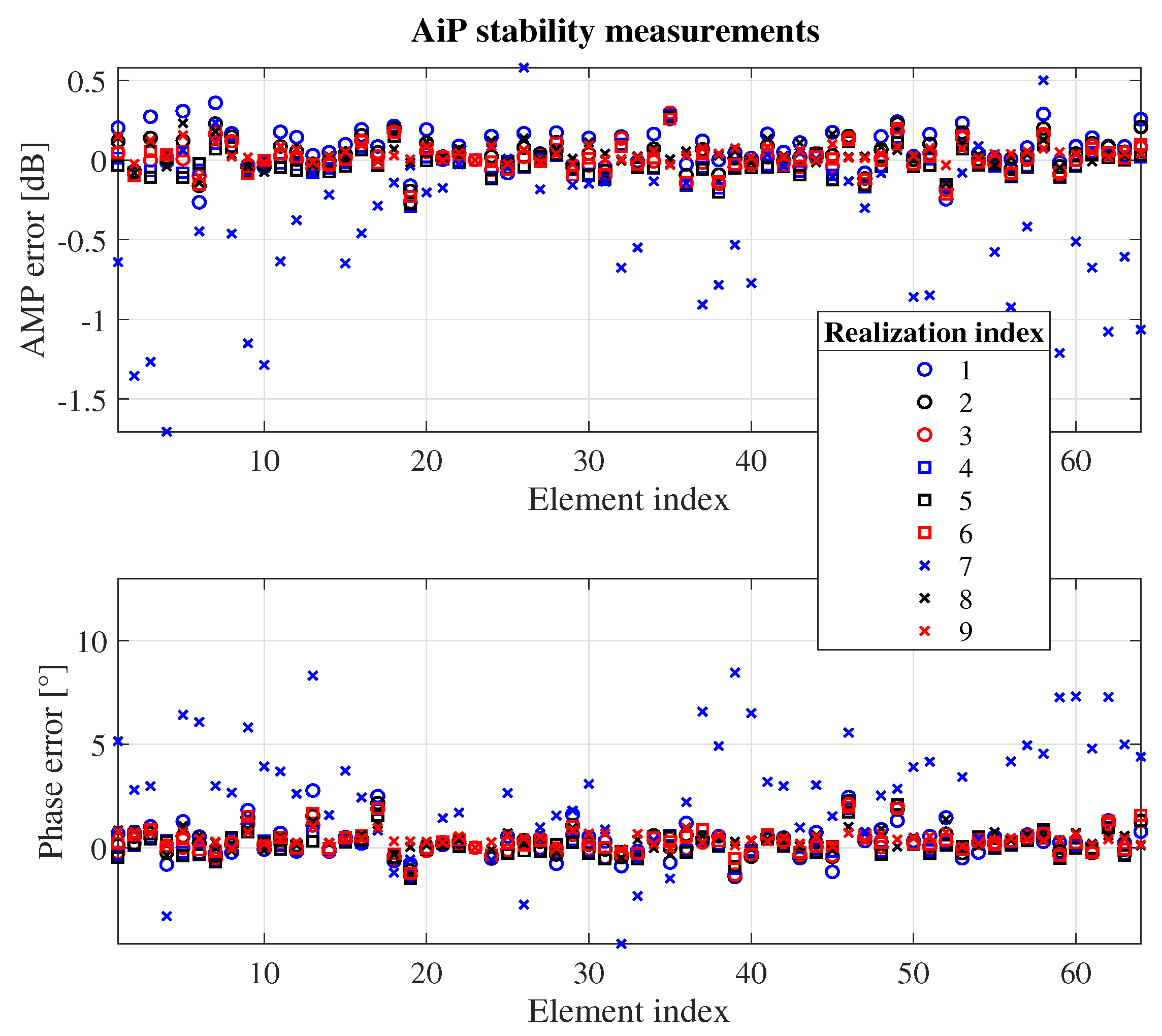
2.2.1. Stability Validation

The measurements are performed in the compact antenna test range (CATR) chamber to ensure the AiP is measured in a clean plane wave condition, as shown in Figure 3. Additionally, the measurement system consists of:
(a)
A VNA operating from 10 MHz to 43.5 GHz.
(b)
A laptop as the control computer that controls the AiP and VNA.
(c)
An adjustable DC Power Supply working on 12 V for the AiP module.
The transmission S-parameters S21 between the AiP and the CATR probe antenna is measured by the VNA at 28 GHz, with the broadside direction of the AiP aligned with the center of the CATR reflector. For this measurement campaign, the AiP is set as the Rx, and the CATR probe antenna is the Tx. In this setup, the probe antenna and the reflector generates plane waves impinging at the AiP phased array. In addition, the Tx power is set to 10 dBm and the intermediate frequency (IF) is set to 10 Hz in the VNA.
The complex least squares method in [23,36] is used here to estimate the calibration coefficients of the AiP elements for 10 repetitions. To investigate the effect of temperature on the stability of the AiP, the AiP is turned on for a period of time to warm up before the calibration measurements, and the first to sixth calibration measurements are performed after the temperature has stabilized. After the sixth calibration measurement, the AiP is turned off to allow it to cool down, and then the AiP is turned on again to perform the seventh through tenth calibration measurements immediately. It is worth mentioning that during each calibration measurement, the temperature of the 16 element chips of the AiP is recorded before each elements phases are reset.
If the tenth calibration measurement is chosen as the reference, the difference between the first nine measurements and the tenth one is shown in Figure 4. From the measurement result, it can be analyzed that, except for the seventh measurement, the rest of the measurements have a good agreement with the tenth one, both in terms of the amplitude and phase excitation of array elements. In addition, the chips temperature records from the measurements show that the average AiP chips temperature is consistent throughout the measurements, except for the seventh measurement. For the 6th, 7th and 10th AiP calibration measurements, the average chips temperature trends are shown in Figure 5. In the 7th measurement, since the AiP is turned off for cooling and then turned on to perform calibration measurements immediately, the average temperature of the AiP chips rises during the early part of the measurement process until it stabilizes. In summary, the operating temperature of the AiP has a significant effect on elements’ stability. Therefore, the AiP should be used in its stable state after the temperature reaching a stable level.

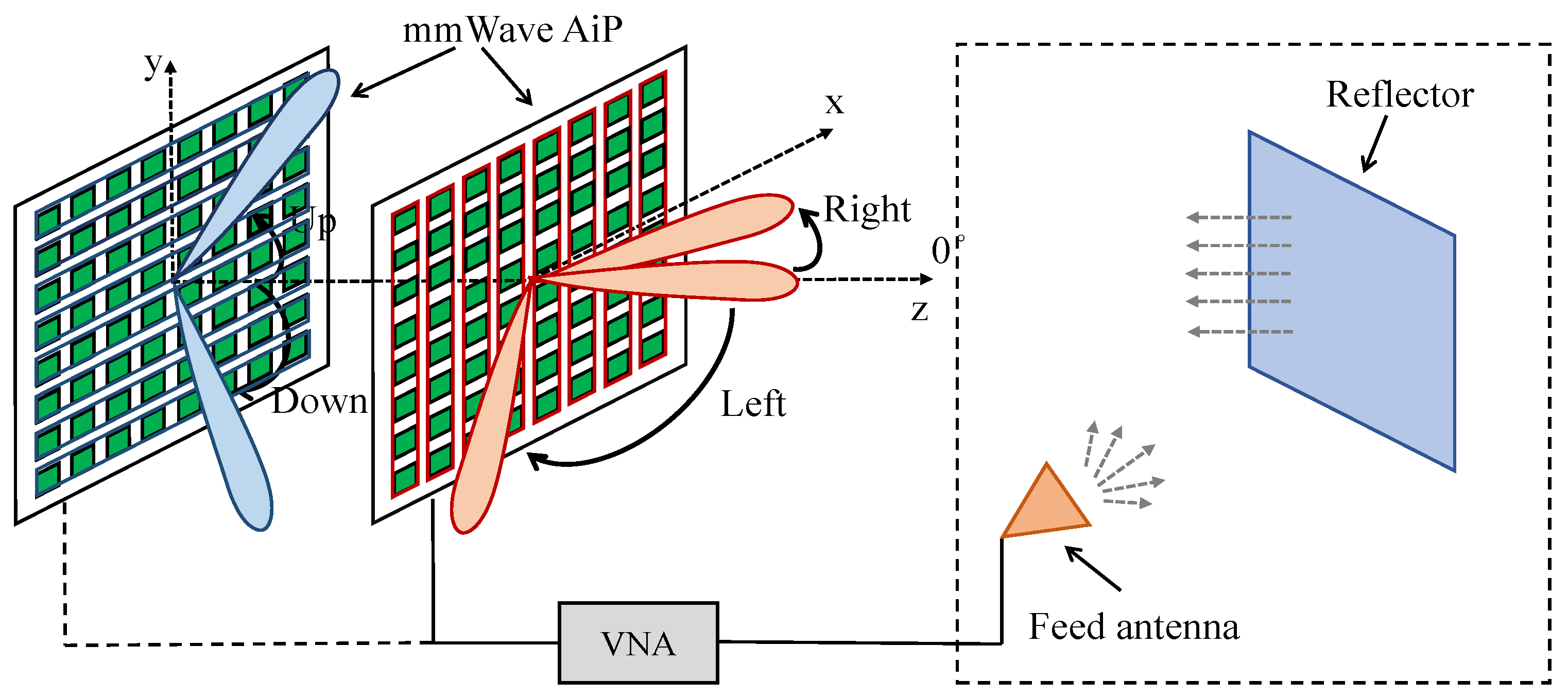
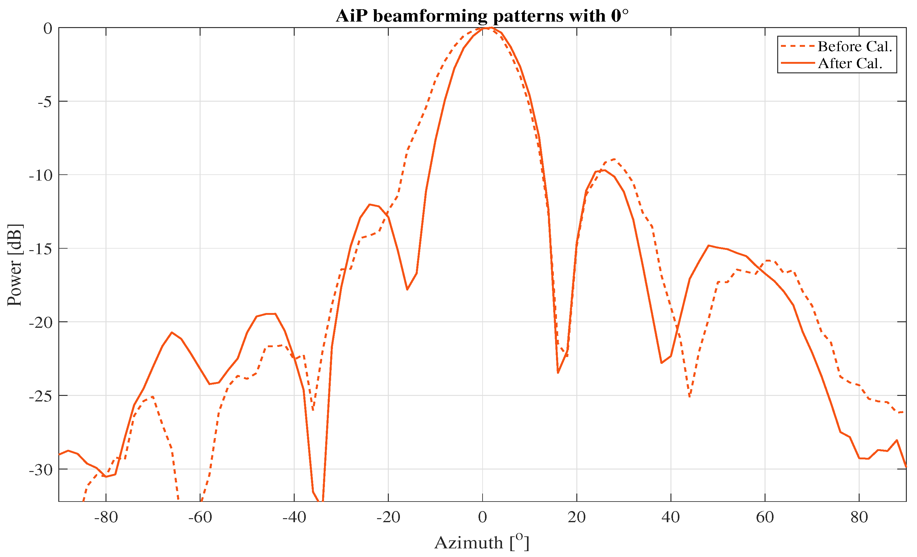
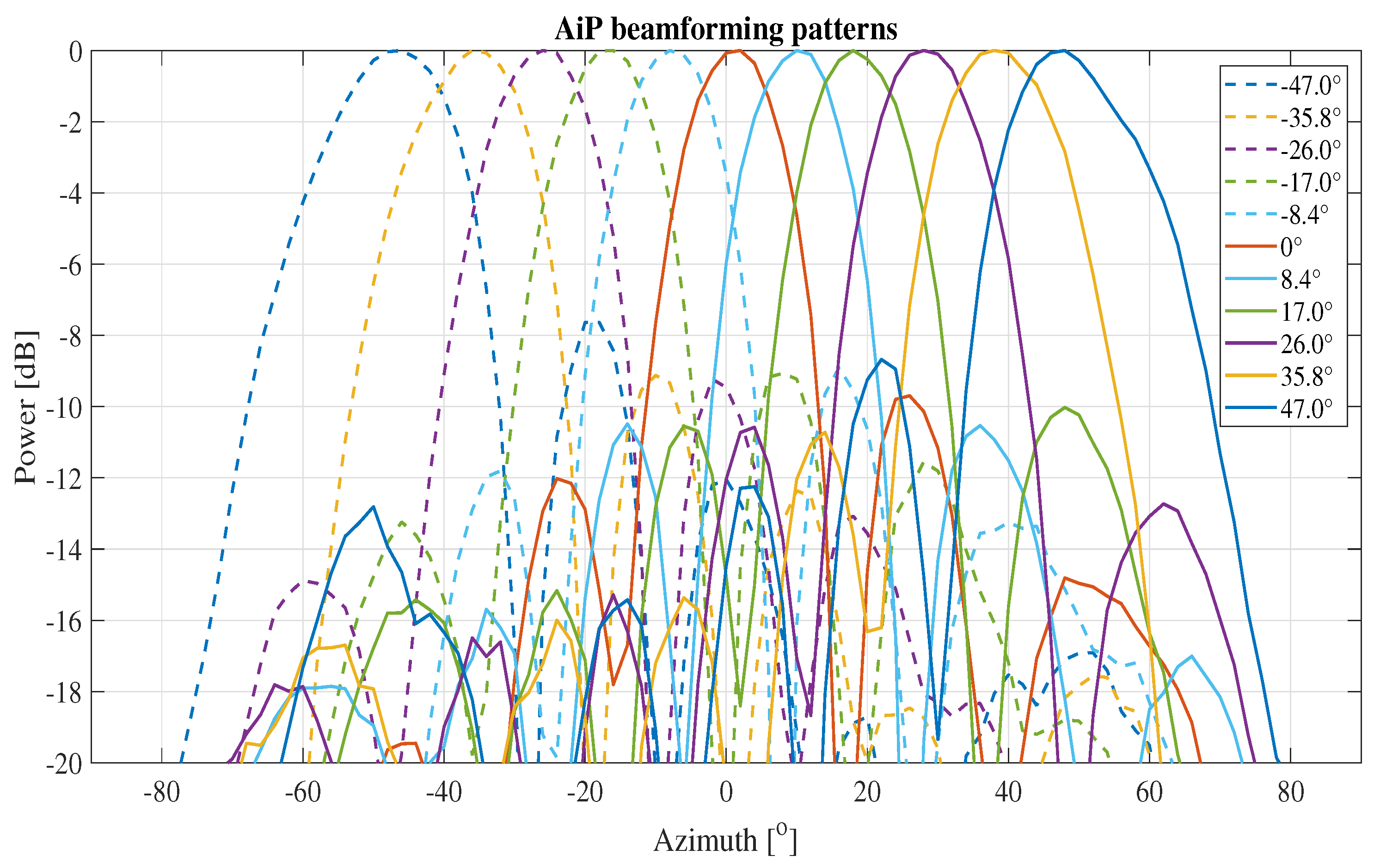
2.2.2. Aip Beamforming Performance Validation

The measurement of beamforming patterns of the AiP is also carried out in the CATR, and the block diagram of the AiP beamforming pattern measurement setup is depicted in Figure 6. Similar to the calibration measurement system setup, the operating mode of the AiP is set to Rx and is placed on the CATR turntable. The AiP performs beamforming in the horizontal plane and AiP output power values are measured by the VNA.
The beamforming patterns measured for the AiP with beam-steering angle of 0°, before and after calibration are shown in Figure 7. The pattern curves were normalised for a better comparison. As can be seen from the figure, the main beam of the beamforming pattern is oriented to 0 ° , and the main beam is about 10 dB above the first side lobes. Also the calibrated AiP beamforming pattern is more symmetrical and the nulls are deeper compared to that without calibration. In addition, the AiP gain is increased by 9.82 dB. Therefore, when the AiP is calibrated, it is able to perform effective beamforming. Additionally, the calibrated AiP beamforming patterns at different angles are presented in Figure 8, where the results are normalized as well. It is shown that the peak directions of the patterns varies with the beam-steering angles, which proves that the AiP beamforming performance.

3. Aip Array Platform Applications

In this section, we apply the 8 × 8 AiP as an experimental platform to investigate the calibration accuracy of the calibration methods on large arrays and the performance of AiP-based channel sounding, respectively.

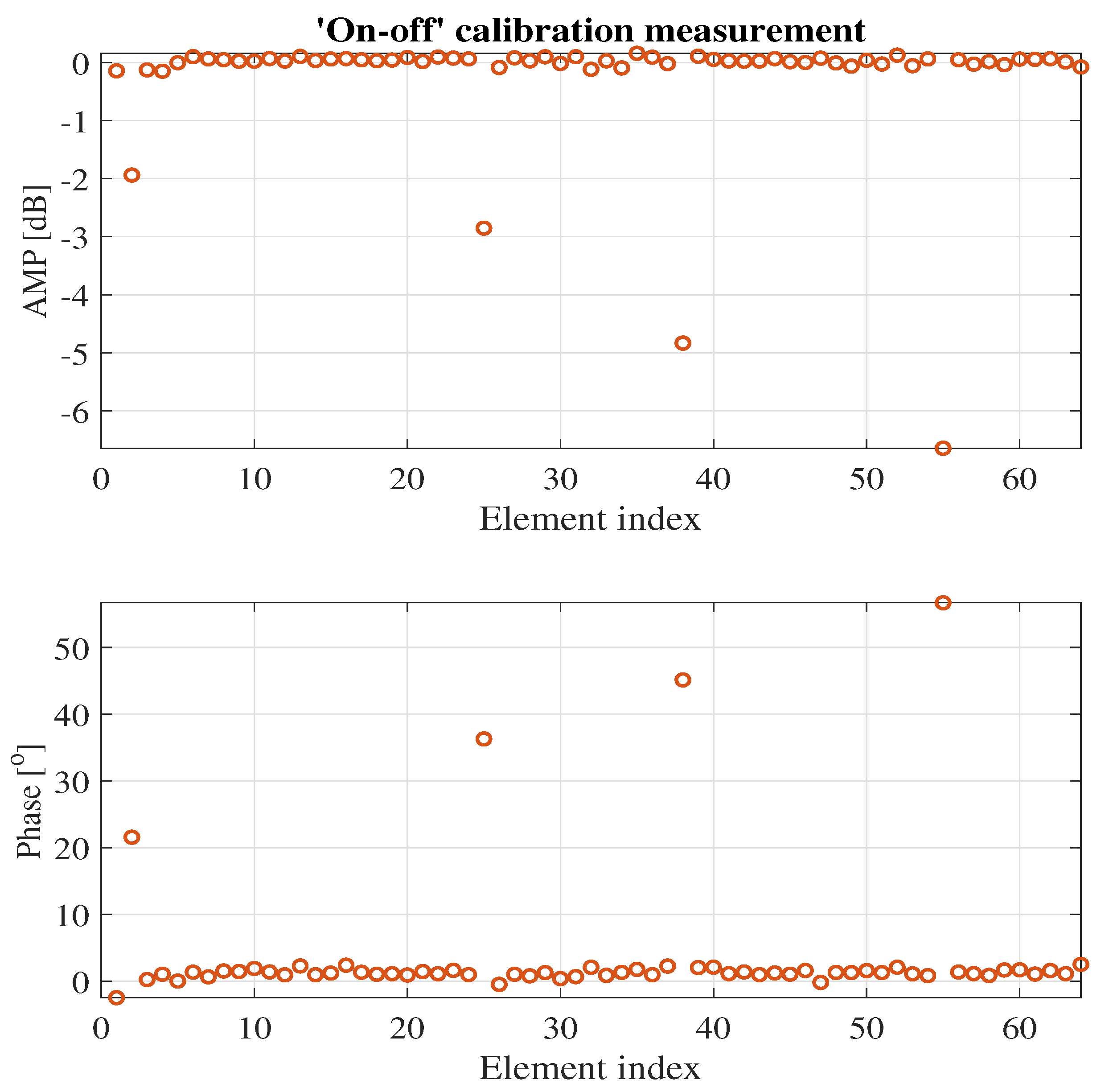
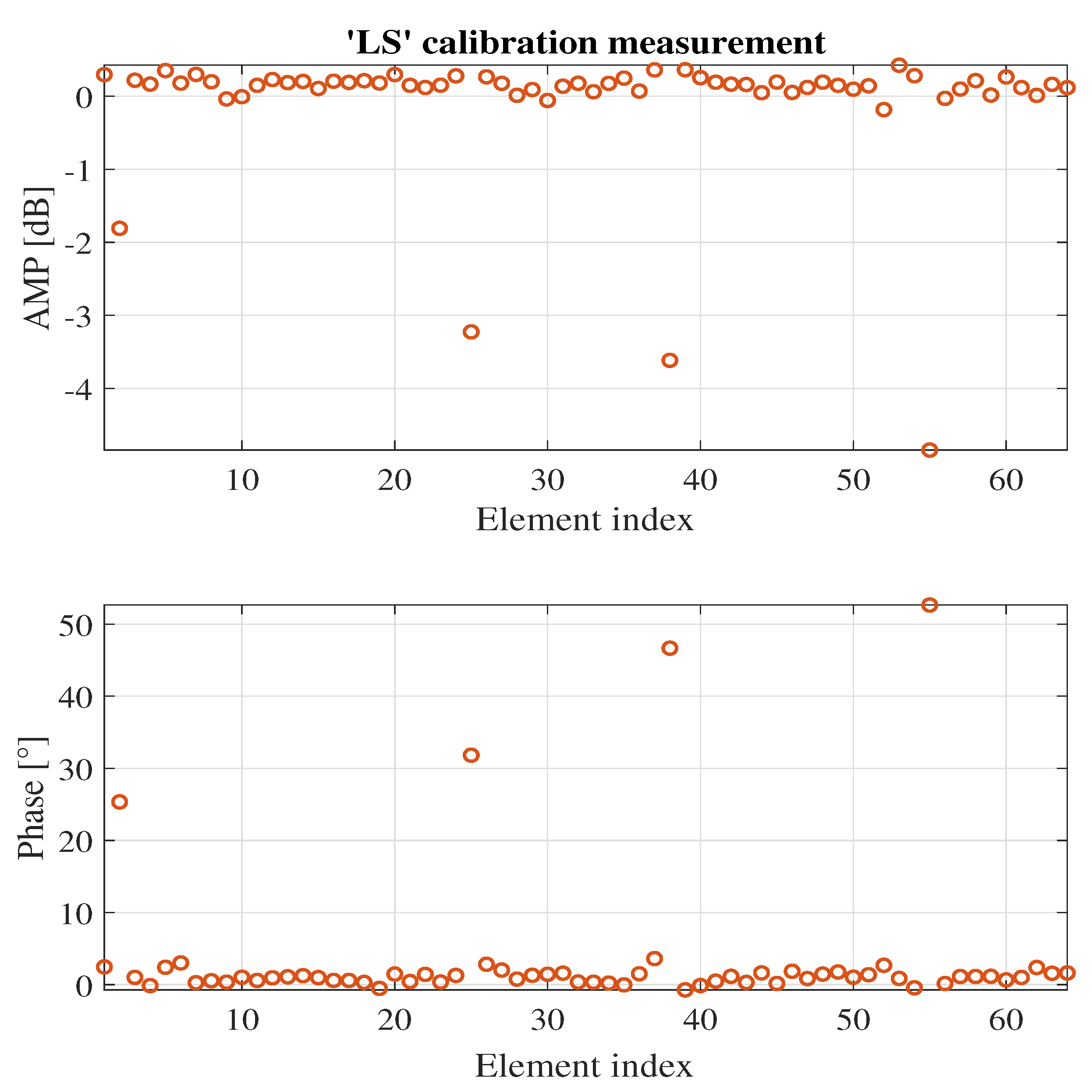
3.1. Investigating the Effectiveness of Calibration Methods on Large Phased Array

The 8 × 8 AiP array with 64 elements is a large array. In this part, this AiP array is used as a validation platform, and the effectiveness of three typical phased array calibration methods: ‘on-off’, ‘inverse’ and ‘least squares’ on large phased array calibration is investigated. Some work has been carried out to investigate the calibration accuracy of these three methods on small and medium phased arrays [22,23,36,37]. For the ‘inverse’ calibration measurement, we first activate all antenna elements of the AiP and set their phase shifter and attenuator to 0° and 0 dB respectively. The S-parameter E o between the AiP and the chamber probe antenna is recorded. Then the phase shifter and attenuator of the mth element are set to −180° and 0 dB in turn for m [ 1 , 64 ] , while the phase shifter and attenuator of the remaining antenna elements are still set to 0° and 0 dB respectively. The S-parameter E m between the AiP and the chamber probe antenna is also recorded. Finally, the initial excitation of the mth element e m = E o E m 2 is obtained.
In order to provide reference values for the calibration results, the phases of the first to fourth elements are set to 22.5°, 33.75°, 45° and 56.25°, and the attenuation of the first to fourth elements is set to −2 dB, −3 dB, −4 dB and −5 dB, respectively. The remaining elements are set to 0° and 0 dB. The ’inverse’ method is applied to calibrate the AiP with and without additional excitation assigned to the first four elements, and the difference between the two calibration results is shown in Figure 9. The amplitude differences of the first four elements are −1.1 dB, −1.7 dB, 0.6 dB and −1.4 dB, respectively. And the phase differences are 26.1°, 18.7°, 32.8° and 33.0°, respectively. Combining the reference values shows that the calibration results have large errors for the intended changed elements. In addition, there are large calibration errors of amplitude for the rest unchanged elements, where the amplitude calculated value of 0 dB. It indicates that the ‘inverse’ method fails to effectively calibrate the AiP with a large array. The AiP array calibration excitation matrix A of ’inverse’ method can be denoted as (1), which the condition number is k ( A ) = 31.3 . Therefore, the condition number of the ’inverse’ calibration excitation matrix is large, which makes the calibration heavily influenced by measurement noise. For this reason the ’inverse’ method is not suitable for calibration on large phased arrays.
A = 1 1 1 1 1 1 1 1 1 1 1 1 9 × 8
Further, the calibration method is replaced by the ‘on-off’ and ’least squares’ methods, taking repeated calibration measurements as described above. The AiP array calibration excitation matrix of ‘least squares’ method is based on the Hadamard matrix [23,36], and the condition number is 1, so the phased array calibration is less affected by the measurement noise. The obtained measurement results are shown in Figure 10 and Figure 11, respectively. The errors between the calibration results of these two methods for the four intended changed elements and the corresponding reference values are shown in Table 1. The measurement results show that both methods are able to perform effective measurements on the AiP array, though there are some errors as expected as well. The errors are mainly introduced by two factors: one is the limited control accuracy of the element attenuator and phase shifter and the second is that during the measurement, there is some measurement noise. In particular, when the element complex filed amplitude is small, the measurement noise has a large impact on the ‘on-off’ calibration accuracy. As shown in Table 1, the calibration error of the ‘on-off’ method for the amplitude of the fourth element reaches 1.5 dB.
In addition, the phased array tends to work with all elements turned on at the same time. When the phased array is calibrated by the ‘least squares’ method, which is an ‘all-on’ method, the circuit state, the platform temperature and the coupling between the element antennas of the array are largely consistent with the working conditions. Therefore, the calibration results of the ‘least squares’ method are closer to the working state of the phased array. If the calibration results of ‘least squares’ is used as a reference, it can be concluded from the similarity of the calibration results of ‘on-off’ and ‘least squares’ that the coupling between the element antennas is small when the AiP array is working. Hence, if the coupling between the element antennas of the phased array is not large, the ‘on-off’ method can also effectively calibrate the phased array.

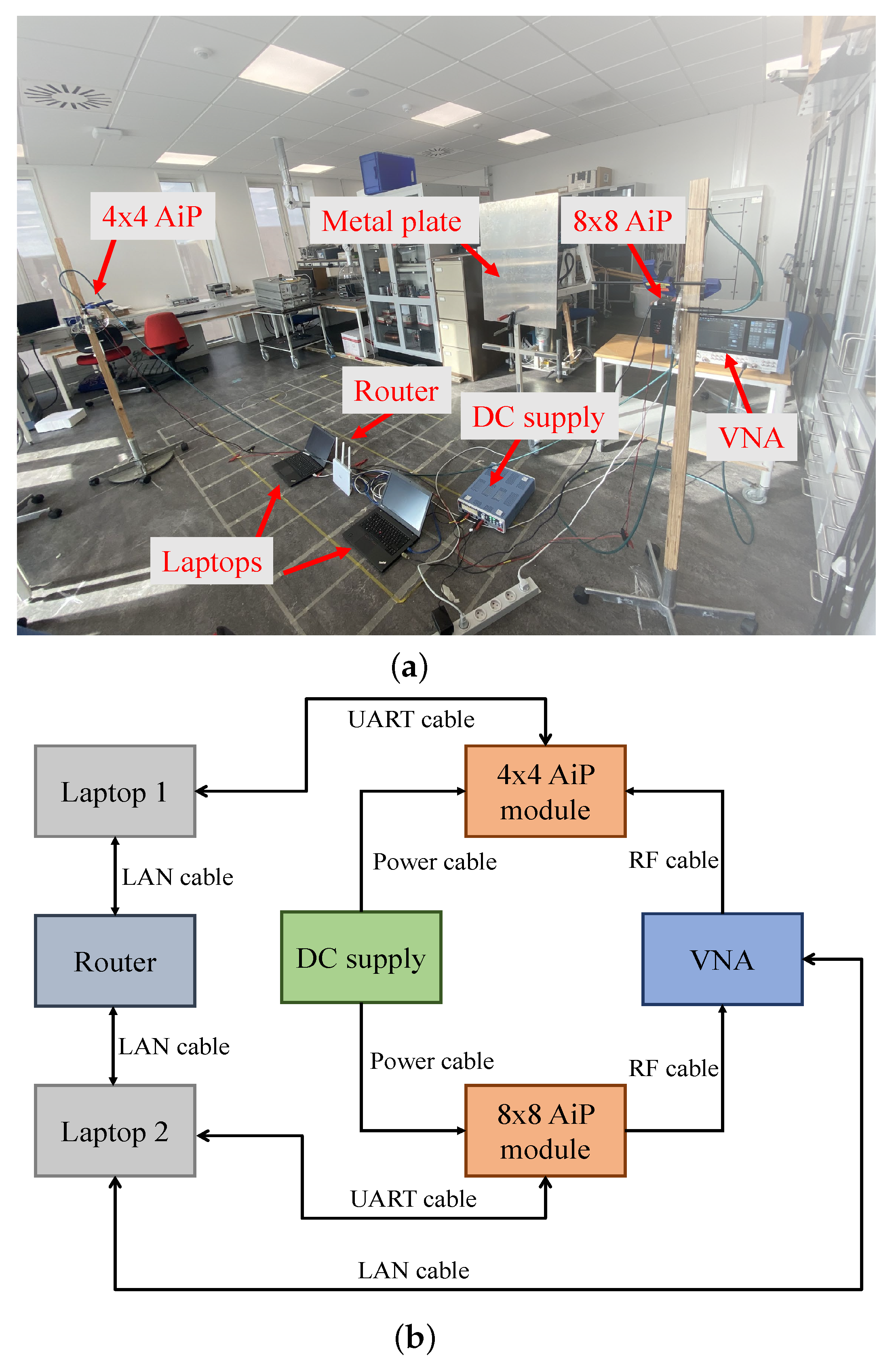
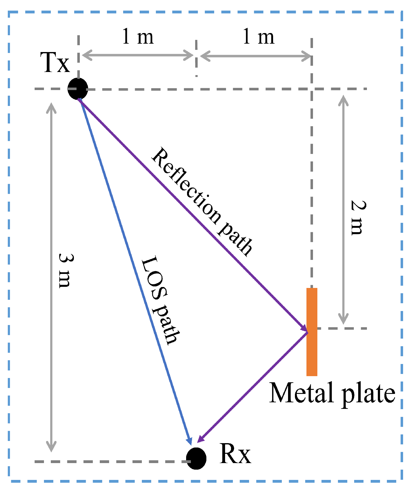
3.2. Mmwave Channel Sounding

Channel Sounding Measurements

Another application of the AiP is in a mmWave channel sounder, where the 4 × 4 AiP described in [22] is employed as the Tx. The environment and system setup of the AiPs channel sounding measurement can be seen in Figure 12. The metal plate is introduced intentionally to act as a reflector in the channel environment, generating a reflection path. Both the Tx and Rx are set at a height of 1.2 m above the floor, and the exact placement of the Tx, the Rx and metal plate is illustrated in Figure 13. Port 1 of the VNA is connected to the Tx and port 2 to the Rx. The channel frequency response between the Tx and Rx is obtained by measuring the S-parameter with the VNA. Laptop 1 is used to control the Tx, laptop 2 is responsible for controlling the Rx and the VNA.
The router is used as a relay for the connection between laptop 1 and laptop 2, and between laptop 2 and the VNA, which is physically connected via LAN cable. In addition, laptop 1 communicates with laptop 2 using TCP/IP and laptop 2 communicates with the VNA via the SCPI protocol. The AiPs are connected to the laptops via UART cables and communicate with the Serial Communication protocol. When the AiPs channel sounder measures the channel, laptop 1 controls the Tx AiP beam-steering, which enables the AiP to beam-steering from −53° to 53° in the horizontal plane. For each beam steered by the Tx AiP, labtop 2 controls the Rx AiP steering beams from −72° to 72° in the horizontal plane. Additionally, laptop 2 also controls the VNA to record the frequency response between the Tx and Rx.

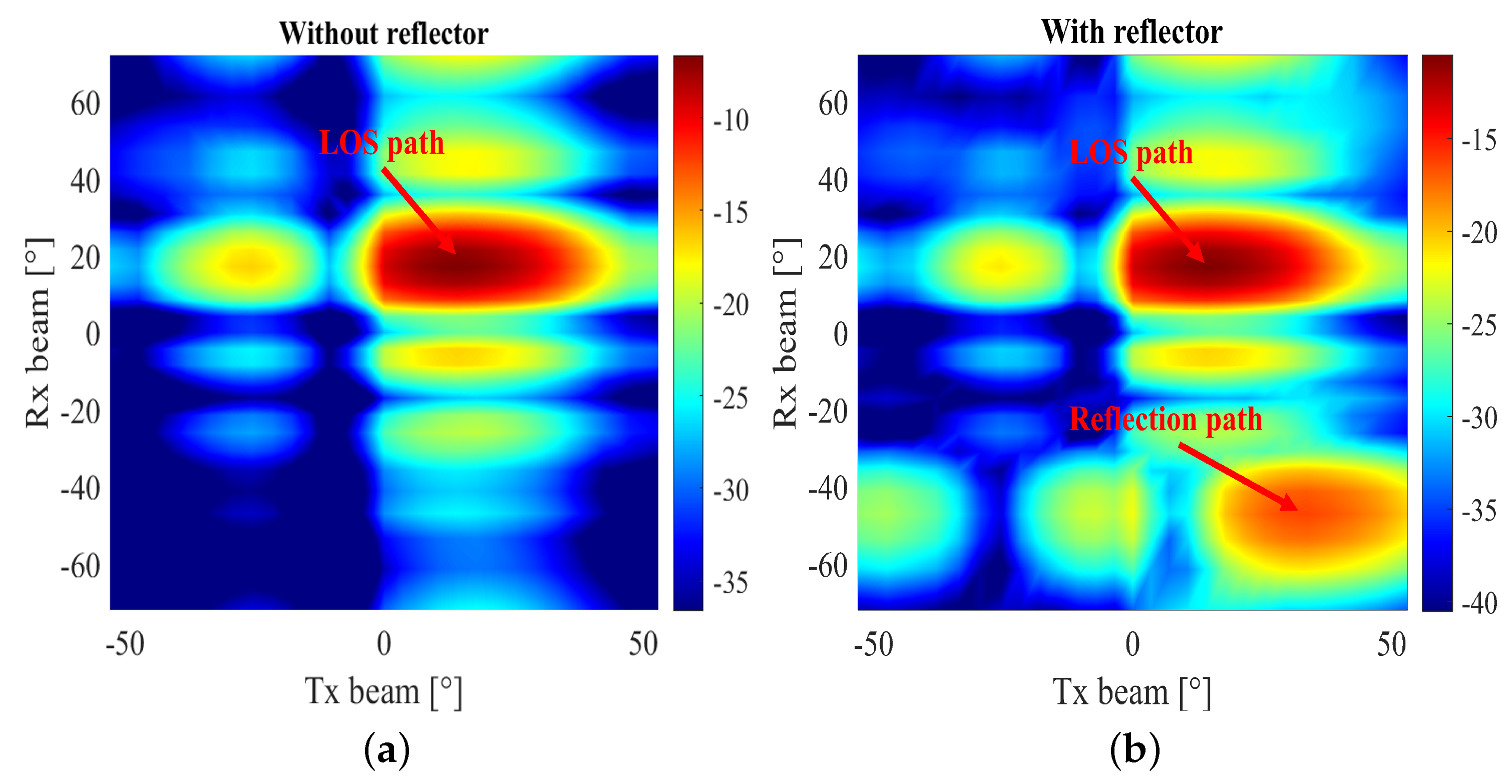
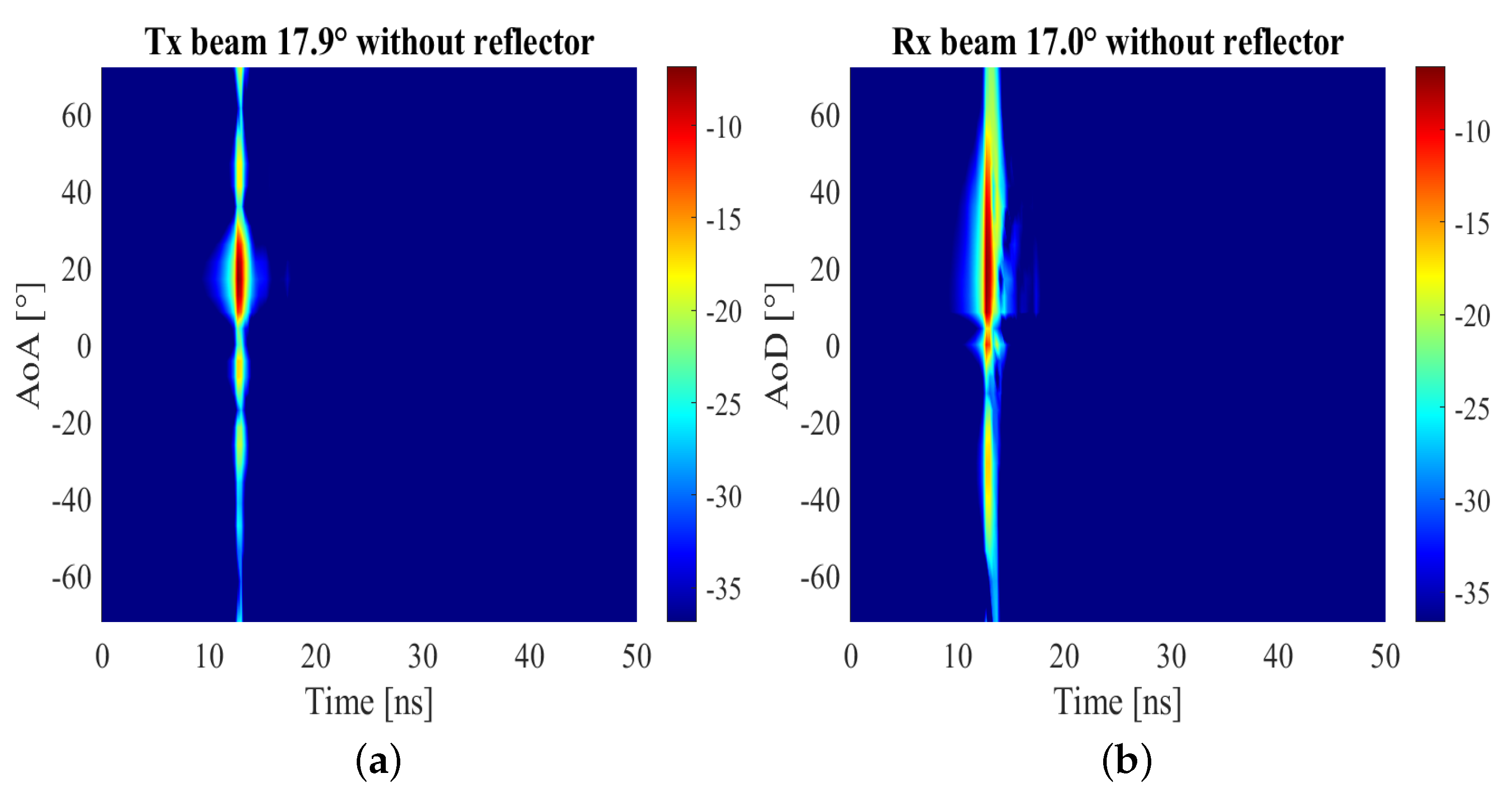
3.3. Channel Sounding Results

The channel sounding measurements results are shown in Figure 14a,b for without and with the metal plate scenario, respectively. The AOD and AOA of the LOS path between Tx and Rx are the same, which is 18.4° calculated according to Figure 13. It can be observed in Figure 14a that the highest peak appears when both the Tx AiP and Rx AiP steering a beam in around 18°, demonstrating that the AiPs based channel sounder is able to accurately detect the LOS propagation path in this channel.
The power angle delay profile (PADP) obtained by the channel sounder for the channel without and with the metal plate when the Tx steering a beam to direction 17.9° is shown in Figure 15a. It is known that path measured is the LOS path with AoA and delay are around 18° and 12.6 ns respectively. Because of the system delay of the AiPs, the delay is larger than the calculated value of 10.05 ns. Similarly, when the Rx AiP beam-steering angle is 17.0°, the measured PADP presented in Figure 15b. The AoA and delay of the measured LOS path are around 18° and 12.6 ns respectively as well. The combination of Figure 15a,b can explain that in Figure 14a, even if there is no propagation path in the vertical and horizontal direction of the LOS path, there is still a certain amount of power lumps measured due to AiPs beam-steering pattern side lobes.
Further, when the metal plate is placed to create a reflection path between the Tx and Rx, as shown in Figure 13. The calculation shows that the AoD anf AoA of the reflection path is 45° and −45° respectively. The measurement result is given in Figure 14b. In comparison to Figure 14a, the channel sounder detects the LOS path as well as the reflection path. It can be seen that the AoA of the reflection path is around 35°, which is different from the calculated value of 45°. This is caused by position error of the metal plate and the directional beam patterns of both AiPs. In addition, when the beam-steering angle of the Tx AiP is 47.5° (the closest angle to 45° at which the Tx AiP performs beam-steering), the measured PADP for the channel is displayed in Figure 16. The measured AoA of the LOS path and the reflection path are around 20° and −45° respectively, both close to the calculated values. The measured delay for the reflection path is 14.67 ns, which is 1.33 ns larger than the calculated one. The delay error is caused by the position errors of the Tx, the Rx and the metal plate, and the system delay of the AiPs.

4. Conclusions

In this paper, the hardware structure and control program of an 8 × 8 AiP array experimental platform are presented. Further, the stability, element weighting control accuracy and beamforming feasibility of the AiP are measured and verified. We also demonstrate that temperature has a high impact on the AiP performance. Then, the calibration accuracy of different calibration methods for large phased array is investigated with the AiP platform. The measurement results show that the calibration accuracy of ’inverse’ method for large phased array is low because it is vulnerable to measurement noise. In addition, if the coupling between the element antennas is small, ‘on-off’ method can be effectively calibrated for phased arrays as well, though better accuracy can be achieved with ‘all-on’ method. Finally, a 26.5–29.5 GHz channel sounder system is designed with the 8 × 8 AiP and a 4 × 4 AiP. In the channel sounding measurements, the DPCs are analysed in terms of AoA, AoD and delay. The results verify that the channel sounder can work effectively. It saves measurement time and simplifies the measurement setup due to the swift beam control capability of the phased array.

Author Contributions

Conceptualization, W.F. and F.Z.; investigation, Y.L. and H.G.; data curation, Y.L.; writing—original draft preparation, Y.L.; writing—review and editing, W.F. and F.Z.; supervision, W.F. and F.Z. All authors have read and agreed to the published version of the manuscript.

Funding

This research received no external funding.

Institutional Review Board Statement

Not applicable.

Informed Consent Statement

Not applicable.

Data Availability Statement

Not applicable.

Acknowledgments

The authors would like to thank Yejian Lv, Zhiqiang Yuan and Kim Olesen for their assistance during the experiments.

Conflicts of Interest

The authors declare no conflict of interest.

References

  1. Hemadeh, I.A.; Satyanarayana, K.; El-Hajjar, M.; Hanzo, L. Millimeter-Wave Communications: Physical Channel Models, Design Considerations, Antenna Constructions, and Link-Budget. IEEE Commun. Surv. Tutor. 2018, 20, 870–913. [Google Scholar] [CrossRef] [Green Version]
  2. Choi, S.T.; Yang, K.S.; Nishi, S.; Shimizu, S.; Tokuda, K.; Kim, Y.H. A 60-GHz point-to-multipoint millimeter-wave fiber-radio communication system. IEEE Trans. Microw. Theory Tech. 2006, 54, 1953–1960. [Google Scholar] [CrossRef]
  3. Gao, H.; Wang, Z.; Zhang, X.; Kyösti, P.; Jing, Y.; Wang, W.; Wu, Y.; Pedersen, G.F.; Fan, W. Over-the-Air Performance Testing of 5G New Radio User Equipment: Standardization and Challenges. IEEE Commun. Stand. Mag. 2022, 6, 71–78. [Google Scholar] [CrossRef]
  4. Guan, K.; Ai, B.; Peng, B.; He, D.; Li, G.; Yang, J.; Zhong, Z.; Kürner, T. Towards Realistic High-Speed Train Channels at 5G Millimeter-Wave Band—Part I: Paradigm, Significance Analysis, and Scenario Reconstruction. IEEE Trans. Veh. Technol. 2018, 67, 9112–9128. [Google Scholar] [CrossRef]
  5. Joshi, K.C.; Niknam, S.; Prasad, R.V.; Natarajan, B. Analyzing the Tradeoffs in Using Millimeter Wave Directional Links for High Data-Rate Tactile Internet Applications. IEEE Trans. Ind. Inform. 2020, 16, 1924–1932. [Google Scholar] [CrossRef] [Green Version]
  6. Boccardi, F.; Heath, R.W.; Lozano, A.; Marzetta, T.L.; Popovski, P. Five disruptive technology directions for 5G. IEEE Commun. Mag. 2014, 52, 74–80. [Google Scholar] [CrossRef] [Green Version]
  7. Technical Report FCC-16-89; Further Notice of Proposed Rulemaking; Federal Communications Commission: Washington, DC, USA, July 2016.
  8. He, R.; Schneider, C.; Ai, B.; Wang, G.; Zhong, Z.; Dupleich, D.A.; Thomae, R.S.; Boban, M.; Luo, J.; Zhang, Y. Propagation Channels of 5G Millimeter-Wave Vehicle-to-Vehicle Communications: Recent Advances and Future Challenges. IEEE Veh. Technol. Mag. 2020, 15, 16–26. [Google Scholar] [CrossRef]
  9. Agiwal, M.; Roy, A.; Saxena, N. Next Generation 5G Wireless Networks: A Comprehensive Survey. IEEE Commun. Surv. Tutor. 2016, 18, 1617–1655. [Google Scholar] [CrossRef]
  10. Ferreira, M.; Pinho, P. Propagation at mmWaves frequencies: Some considerations. In Proceedings of the 2021 Telecoms Conference (ConfTELE), Leiria, Portugal, 11–12 February 2021; pp. 1–4. [Google Scholar] [CrossRef]
  11. Ghosh, A.; Thomas, T.A.; Cudak, M.C.; Ratasuk, R.; Moorut, P.; Vook, F.W.; Rappaport, T.S.; MacCartney, G.R.; Sun, S.; Nie, S. Millimeter-Wave Enhanced Local Area Systems: A High-Data-Rate Approach for Future Wireless Networks. IEEE J. Sel. Areas Commun. 2014, 32, 1152–1163. [Google Scholar] [CrossRef]
  12. Liao, S.; Wu, P.; Shum, K.M.; Xue, Q. Differentially Fed Planar Aperture Antenna With High Gain and Wide Bandwidth for Millimeter-Wave Application. IEEE Trans. Antennas Propag. 2015, 63, 966–977. [Google Scholar] [CrossRef]
  13. Briqech, Z.; Sebak, A.R.; Denidni, T.A. Wide-Scan MSC-AFTSA Array-Fed Grooved Spherical Lens Antenna for Millimeter-Wave MIMO Applications. IEEE Trans. Antennas Propag. 2016, 64, 2971–2980. [Google Scholar] [CrossRef]
  14. Guo, J.; Liao, S.; Xue, Q.; Xiao, S. Planar Aperture Antenna With High Gain and High Aperture Efficiency for 60-GHz Applications. IEEE Trans. Antennas Propag. 2017, 65, 6262–6273. [Google Scholar] [CrossRef]
  15. Rupakula, B.; Nafe, A.; Zihir, S.; Wang, Y.; Lin, T.W.; Rebeiz, G. 63.5–65.5-GHz Transmit/Receive Phased-Array Communication Link With 0.5–2 Gb/s at 100–800 m and ± 50° Scan Angles. IEEE Trans. Microw. Theory Tech. 2018, 66, 4108–4120. [Google Scholar] [CrossRef]
  16. Gu, X.; Liu, D.; Baks, C.; Tageman, O.; Sadhu, B.; Hallin, J.; Rexberg, L.; Parida, P.; Kwark, Y.; Valdes-Garcia, A. Development, Implementation, and Characterization of a 64-Element Dual-Polarized Phased-Array Antenna Module for 28-GHz High-Speed Data Communications. IEEE Trans. Microw. Theory Tech. 2019, 67, 2975–2984. [Google Scholar] [CrossRef]
  17. Wang, Y.; Chung, H.; Ma, Q.; Rebeiz, G.M. A 57.5–65.5 GHz Phased-Array Transmit Beamformer in 45 nm CMOS SOI With 5 dBm and 6.1 Linear PAE for 400 MBaud 64-QAM Waveforms. IEEE Trans. Microw. Theory Tech. 2021, 69, 1772–1779. [Google Scholar] [CrossRef]
  18. Herd, J.S.; Conway, M.D. The Evolution to Modern Phased Array Architectures. Proc. IEEE 2016, 104, 519–529. [Google Scholar] [CrossRef]
  19. Zhang, Y.P.; Liu, D. Antenna-on-Chip and Antenna-in-Package Solutions to Highly Integrated Millimeter-Wave Devices for Wireless Communications. IEEE Trans. Antennas Propag. 2009, 57, 2830–2841. [Google Scholar] [CrossRef]
  20. Zhang, Y.; Mao, J. An Overview of the Development of Antenna-in-Package Technology for Highly Integrated Wireless Devices. Proc. IEEE 2019, 107, 2265–2280. [Google Scholar] [CrossRef]
  21. Zwenger, C.; Chaudhry, V. Antenna in package (AiP) technology for 5G growth. Chip Scale Rev. March/April 2020, 351. Available online: https://www.chipscalereview.com/wp-content/uploads/2021/01/ChipScale_Mar-Apr_2020-wp.pdf (accessed on 28 November 2022).
  22. Gao, H.; Wang, W.; Fan, W.; Zhang, F.; Wang, Z.; Wu, Y.; Liu, Y.; Pedersen, G.F. Design and Experimental Validation of Automated Millimeter-Wave phased Array Antenna-in-Package (AiP) Experimental Platform. IEEE Trans. Instrum. Meas. 2021, 70, 1–11. [Google Scholar] [CrossRef]
  23. Zhang, F.; Fan, W.; Wang, Z.; Zhang, Y.; Pedersen, G.F. Improved Over-the-Air Phased Array Calibration Based on Measured Complex Array Signals. IEEE Antennas Wirel. Propag. Lett. 2019, 18, 1174–1178. [Google Scholar] [CrossRef] [Green Version]
  24. Seiji, M.; Katagi, T. A method for measuring amplitude and phase of each radiating element of a phased array antenna. Electron. Commun. Jpn. Part Commun. 1982, J65-B, 555–560. [Google Scholar] [CrossRef]
  25. Takahashi, T.; Konishi, Y.; Chiba, I. A Novel Amplitude-Only Measurement Method to Determine Element Fields in Phased Arrays. IEEE Trans. Antennas Propag. 2012, 60, 3222–3230. [Google Scholar] [CrossRef]
  26. Long, R.; Ouyang, J.; Yang, F.; Han, W.; Zhou, L. Fast Amplitude-Only Measurement Method for Phased Array Calibration. IEEE Trans. Antennas Propag. 2017, 65, 1815–1822. [Google Scholar] [CrossRef]
  27. Hejselbæk, J.; Nielsen, J.; Fan, W.; Pedersen, G.F. Measured 21.5 GHz Indoor Channels With User-Held Handset Antenna Array. IEEE Trans. Antennas Propag. 2017, 65, 6574–6583. [Google Scholar] [CrossRef] [Green Version]
  28. Mbugua, A.W.; Fan, W.; Olesen, K.; Cai, X.; Pedersen, G.F. Phase-Compensated Optical Fiber-Based Ultrawideband Channel Sounder. IEEE Trans. Microw. Theory Tech. 2020, 68, 636–647. [Google Scholar] [CrossRef]
  29. Zwick, T.; Beukema, T.; Nam, H. Wideband channel sounder with measurements and model for the 60 GHz indoor radio channel. IEEE Trans. Veh. Technol. 2005, 54, 1266–1277. [Google Scholar] [CrossRef]
  30. Zhang, F.; Fan, W.; Pedersen, G.F. Frequency-Invariant Uniform Circular Array for Wideband mm-Wave Channel Characterization. IEEE Antennas Wirel. Propag. Lett. 2017, 16, 641–644. [Google Scholar] [CrossRef] [Green Version]
  31. Lyu, Y.; Kyösti, P.; Fan, W. Sub-THz VNA-based Channel Sounder Structure and Channel Measurements at 100 and 300 GHz. In Proceedings of the 2021 IEEE 32nd Annual International Symposium on Personal, Indoor and Mobile Radio Communications (PIMRC), Helsinki, Finland, 13–16 September 2021; pp. 1–5. [Google Scholar] [CrossRef]
  32. Li, M.; Zhang, F.; Zhang, X.; Lyu, Y.; Fan, W. Omni-Directional Pathloss Measurement Based on Virtual Antenna Array With Directional Antennas. IEEE Trans. Veh. Technol. 2022, 1–5. [Google Scholar] [CrossRef]
  33. Caudill, D.; Chuang, J.; Jun, S.Y.; Gentile, C.; Golmie, N. Real-Time mmWave Channel Sounding Through Switched Beamforming With 3-D Dual-Polarized Phased-Array Antennas. IEEE Trans. Microw. Theory Tech. 2021, 69, 5021–5032. [Google Scholar] [CrossRef]
  34. Chopra, A.; Thornburg, A.; Kanhere, O.; Termos, A.; Ghassemzadeh, S.S.; Rappaport, T.S. Real-time Millimeter Wave Omnidirectional Channel Sounder Using Phased Array Antennas. In Proceedings of the GLOBECOM 2020-2020 IEEE Global Communications Conference, Taipei, Taiwan, 7–11 December 2020; pp. 1–7. [Google Scholar] [CrossRef]
  35. Wang, Y.; Phelps, T.; Kibaroglu, K.; Sayginer, M.; Ma, Q.; Rebeiz, G.M. 28 GHz 5G-Based Phased-Arrays for UAV Detection and Automotive Traffic-Monitoring Radars. In Proceedings of the 2018 IEEE/MTT-S International Microwave Symposium-IMS, Philadelphia, PA, USA, 10–15 June 2018; pp. 895–898. [Google Scholar] [CrossRef]
  36. Long, R.; Ouyang, J.; Yang, F.; Han, W.; Zhou, L. Multi-Element Phased Array Calibration Method by Solving Linear Equations. IEEE Trans. Antennas Propag. 2017, 65, 2931–2939. [Google Scholar] [CrossRef]
  37. Gao, H.; Wang, W.; Wu, Y.; Liu, Y.; Pedersen, G.F.; Fan, W. Experimental Comparison of On–Off and All-On Calibration Modes for Beam-Steering Performance of mmWave Phased Array Antenna-in-Package. IEEE Trans. Instrum. Meas. 2021, 70, 1–9. [Google Scholar] [CrossRef]
Figure 1. (a) Photograph and (b) chips and antennas layout of the 8 × 8 AiP model.
Electronics 11 04055 g001
Figure 2. Block diagram of the 8 × 8 AiP.
Electronics 11 04055 g002
Figure 3. Photograph of the AiP calibration measurement setup.
Electronics 11 04055 g003
Figure 4. AiP elements stability measurement results.
Electronics 11 04055 g004
Figure 5. Chips average temperature measurements.
Electronics 11 04055 g005
Figure 6. Block diagram of the AiP beamforming pattern measurement setup.
Electronics 11 04055 g006
Figure 7. AiP beamforming patterns at 0° without and with calibration.
Electronics 11 04055 g007
Figure 8. AiP beamforming patterns at different angles.
Electronics 11 04055 g008
Figure 9. ‘Inverse’ calibration effectiveness measurement results.
Electronics 11 04055 g009
Figure 10. ‘On-off’ calibration effectiveness measurement results.
Electronics 11 04055 g010
Figure 11. ‘Least squares’ calibration effectiveness measurement results.
Electronics 11 04055 g011
Figure 12. (a) Photograph and (b) block diagram of the AiPs channel sounder setup.
Electronics 11 04055 g012
Figure 13. Placement of the Tx, Rx and metal plate.
Electronics 11 04055 g013
Figure 14. (a) Without the metal plate and (b) with the metal plate results of the channel sounding.
Electronics 11 04055 g014
Figure 15. PADP of channel with (a) Tx beam-steering at 17.9° and (b) Rx beam-steering at 17.0°.
Electronics 11 04055 g015
Figure 16. PADP of channel with Tx beam-steering at 47.5° and with the reflector.
Electronics 11 04055 g016
Table 1. Variation between the results of AiP elements calibration measurements.
Element‘On-off’ Amp. Err. [dB]‘LS’ Amp. Err. [dB]‘On-off’ Pha. Err. [°]‘LS’ Pha. Err. [°]
1−0.2−0.21.62.8
2−0.30.25.0−1.9
30.7−0.42.61.7
41.5−0.22.9−3.6
Publisher’s Note: MDPI stays neutral with regard to jurisdictional claims in published maps and institutional affiliations.

