Article

Integral Windup Resetting Enhancement for Sliding Mode Control of Chemical Processes with Longtime Delay

1
Departamento de Ingeniería de Sistemas y Computación, Universidad Católica del Norte, Antofagasta 1270709, Chile
2
Departamento de Automatización y Control Industrial, Escuela Politénica Nacional, Quito 170525, Ecuador
3
Product Development, Plexigrid S.L., 33510 Gijón, Spain
4
Colegio de Ciencias e Ingenierías “El Politécnico”, Universidad San Francisco de Quito USFQ, Quito 170157, Ecuador
*
Author to whom correspondence should be addressed.
Electronics 2022, 11(24), 4220; https://doi.org/10.3390/electronics11244220
Submission received: 31 October 2022 / Revised: 9 December 2022 / Accepted: 12 December 2022 / Published: 18 December 2022
(This article belongs to the Special Issue Sliding Mode Control in Dynamic Systems)

Abstract

:
The effects of the windup phenomenon impact the performance of integral controllers commonly found in industrial processes. In particular, windup issues are critical for controlling variable and longtime delayed systems, as they may not be timely corrected by the tracking error accumulation and saturation of the actuators. This work introduces two anti-windup control algorithms for a sliding mode control (SMC) framework to promptly reset the integral control action in the discontinuous mode without inhibiting the robustness of the overall control system against disturbances. The proposed algorithms are intended to anticipate and steer the tracking error toward the origin region of the sliding surface based on an anti-saturation logistic function and a robust compensation action fed by system output variations. Experimental results show the effectiveness of the proposed algorithms when they are applied to two chemical processes, i.e., (i) a Variable Height Mixing Tank (VHMT) and (ii) Continuous Stirred Tank Reactor (CSTR) with a variable longtime delay. The control performance of the proposed anti-windup approaches has been assessed under different reference and disturbance changes, exhibiting that the tracking control performance in the presence of disturbances is enhanced up to 24.35% in terms of the Integral Square Error (ISE) and up to 88.7% regarding the Integral Time Square Error (ITSE). Finally, the results of the proposed methodology demonstrated that the excess of cumulative energy by the actuator saturation could reduce the process resources and also extend the actuator’s lifetime span.

1. Introduction

One of the major challenges when designing controllers for industrial processes is the time delay, which comprehends an inherent characteristic in several dynamics systems that impacts the information synchronization and control performance. This is the case of food, chemical, biological, and agricultural processes, which usually include systems that exhibit variable and longtime delays due to the accumulation of low transient responses [1,2,3]. The time delay, so-called dead-time, can be found either in the process input or output, where lag dynamics can directly impair the nominal performance of the control loop [4]. When this time issue appears in the process input, it indicates that the system dynamics are associated with delays in the actuation channels. Therefore, the control action can hardly be applied on time, and the control efficiency may be deteriorated against disturbances [5]. On the other hand, the delay in the process output can be associated with the measurement process and sensors/instrumentation systems, under which the controller could acquire outdated information. In both cases, delays typically impose strict limitations on feasibility and performance [6]. For instance, high-torque mixing machines take considerable time to recover their inertia [7], exhibiting a time delay in the process output. This delay is usually propagated to other processes or instrumentation and communication systems, in which controllers could be fed by non-updated system information [8]. In this scenario, the presence of delays typically demands conditions on the computational activity and control performance [9].
The sliding mode control (SMC) strategy arises as a suitable control technique to deal with delayed systems by its simplicity [10,11,12]. The SMC strategy is appealing since the design procedure usually considers a reduced order model concerning the original one, simplifying the decoupling of delayed dynamics in linear and nonlinear processes [13,14,15]. The SMC strategy also can maintain control robustness against uncertainties and modeling mismatch errors when the system states remain within a sliding mode surface, thus excluding the need for exact modeling [16,17]. However, robust control performance can be compromised in processes with time-varying parameters, such as systems with variable dead time [18,19]. In practice, hybrid control strategies combining SMC and PID (i.e., Proportional, Integral, and Derivative) control are usually used in industrial processes to complement a proper tracking performance with stability. Nevertheless, such integration within a sliding surface usually presents an unbounded growth of the control action due to the need for error correction, thus leading to the saturation of the actuators, a phenomenon known as windup. The windup occurrence is precisely related to the lack of a quick reaction from a controller against the continuous accumulation of the tracking error [20]. As a consequence of the windup phenomenon, the control performance is degraded, generating a large overshoot, long settling time, and system instability [21,22].
To overcome the effects of the windup phenomenon on the error accumulation, several anti-windup and anti-saturation techniques have been proposed in the literature [23,24,25] which may be categorized into three perspectives [26]: (i) conditional integration, (ii) tracking back calculation and (iii) bounded integration of the tracking error. In the conditional integration approach [27], stand-by conditions are activated in order to suspend the integral control action as the control input increases up to a certain maximum control limit or up to the control input is close to being saturated. When there is no presence of saturation in the actuators or the output variables, the integral term of the original controller is idled. Under the back calculation scheme, the control does not instantaneously reset the integral action but dynamically with a given time constant before the system output saturates. Under this approach, the difference between saturated and unsaturated input signals is used to produce feedback signals that inhibit the integrator output. Particularly, using transient responses to lessen the integral action is preferable rather than frequently re-turning gains of controllers because they change performance but do not reduce the tracking error accumulation [28]. On the other hand, the bounded integration approach does not allow for a wide range of compensation but shortens the error correction [29]. The integrator value is bounded here with high-gain dead zones to assure a linear operation behavior [30]. For instance, the authors in [31] present a comparison between classic and current anti-windup SMC approaches with event-triggering strategies to reduce the number of control updates. The authors in [32] exposed an anti-windup approach with an auxiliary feedback loop that feeds an integration block with the saturation error; however, it was not accounted for the system output dynamics. In [33], an integral sliding mode approach is used along with an ancillary controller to reject disturbances and track nominal trajectories (disturbance-free). Similarly, in [34], a static windup correction method was evaluated to decelerate an integrator when approaching the saturation region in an SMC.
According to the current state of the art, none of the early works consider rebooting the integral control action included in an SMC control framework to avoid the windup effects. Thus, the main contribution of this work lies in: (a) developing, testing, and validating a resetting strategy of the integral control action in the discontinuous component of the proposed SMC and (b) limiting the amplitude and repeatability of the windup based on an anti-saturation logistic function and a robust compensation action fed by the system output variations. Moreover, the proposed approach also copes with the windup phenomenon in variable time-delay processes, as found in thermal stream mixing systems of the industrial field. This work comprises an extended version of the work in [20], incorporating here the validity of the anti-windup algorithms over a wide variety of control approaches and a series of experiments on a Variable Height Mixing Tank (VHMT) and on a Continuous Stirred Tank Reactor (CSTR). In addition, the control performance is evaluated against process disturbances by using the Integral Square Error (ISE), and the Integral Time-Square Error (ITSE) as assessment metrics [35,36].
The remainder of this paper is structured as follows: Section 2 presents some theoretical concepts of SMC that allow for raising the problem formulation. Then, Section 3 exposes the proposed windup resetting algorithms to correct the integral control action and avoid the saturation of the actuators. The process models in which the anti-windup algorithms were tested are presented in Section 4. Results of the proposed anti-windup strategies tested on the VHMT and CSTR are detailed in Section 5 and Section 6, respectively. Finally, conclusions of this work are drawn in Section 7.

2. Problem Formulation

The SMC is a robust control technique derived from a Variable Structure Control (VSC) scheme. It is appealing due to its capability to handle time-varying systems, modeling mismatch, or system parameter variations [37]. Insights from this control strategy lie in preparing a sliding surface σ ( t ) , which defines the required dynamics of the closed-loop system. The current state trajectory drives along a given surface until the final state is reached, generally designed to be the system reference.
After the sliding surface is selected, the control output is computed as the sum of a pair of control actions, i.e., (a) a continuous control action U C ( t ) , which stands for the sliding mode, and (b) a discontinuous or switching control action U D ( t ) :
U ( t ) = U C ( t ) + U D ( t )
where the continuous part U C ( t ) is responsible for maintaining the trajectory of the system dynamics within the sliding mode surface until reaching the desired system state. This part of the control action is usually obtained by the Filippov’s equivalent [38] and under the null conditions of the error and its derivative (i.e., σ ( t ) = 0 , and σ ˙ ( t ) = 0 ).
The discontinuous control action, on the other hand, represents the reachability mode of the controller. This mode aims to rapidly achieve the system state beginning from the initial condition to σ ( t ) and constantly pointing out to the sliding mode surface. Furthermore, the discontinuous part of the SMC can be formulated as a non-linear switching function as follows:
U D ( t ) = K D sgn ( σ ( t ) )
The chattering phenomenon is the main concern in SMC because of the high control activity produced by the control output variations (2) along the sliding surface σ ( t ) [15]. To reduce such effects, several approaches have been proposed (see [6] and references therein). One of the most widely used strategies lies in smoothing the switching Equation (2) using soft logistic activation functions, such as the sigmoid function [23]. Therefore, the discontinuous control part U D from (2) using the smoothing sigmoid function can be rewritten as follows:
U D ( t ) = K D σ ( t ) | σ ( t ) | + δ
where K D and δ are parameters obtained from a previous setting to fine-tune the discontinuous region of σ [6]. In particular, the parameter δ stands for the width of the sliding mode surface where the chattering effect may occur. Note that a wide variety of softening functions could be used, such as ReLU, max, hyperbolic, geometrical functions, or others [23]; nevertheless, the proposed softening function has been selected here since it fits the control design without compromising computational burden.

2.1. Integral Control Law for the SMC

A First Order Plus Dead-Time (FOPDT) process model is proposed to represent the non-linear delayed system dynamics and design the SMC control strategy. The time-delayed process model is simplified with Taylor’s approximation since high-order structures could introduce complex formulations [30]. Therefore, the process model is assumed to be as follows:
G ( s ) = Y ( s ) U ( s ) K ( τ s + 1 ) ( 1 + t 0 s )
where G ( s ) is the process model composed of the model output Y ( s ) and model input U ( s ) ; K is the process gain; τ denotes the process time constant; and t 0 is the process dead-time. Using G ( s ) from (4), the control law [30] becomes:
U ( t ) = τ t 0 K Y ( t ) τ t 0 + λ 0 e ( t ) + K D σ ( t ) σ ( t ) + δ
where e ( t ) describes the trajectory tracking error; t 0 denotes the transportation lag; Y ( t ) is the process variable. The sliding mode surface can be written as follows:
σ ( t ) = sgn ( K ) d Y ( t ) d t + λ 1 e ( t ) + λ 0 e ( t ) d t
where λ 1 = t 0 + τ τ t 0 and λ 0 < λ 1 2 4 are the adjustable parameters of the sliding mode control surface [30]; e ( t ) is the tracking error between the reference Y ref ( t ) and Y ( t ) . Note that sgn ( K ) in (6) is only a sign function of the static gain K to indicate the controller action (direct or reverse); therefore, it does not affect the sliding mode region or change the control switching over U ( t ) . In addition, note that an integral term in the sliding mode surface is included in the control formulation. Thus, as the tracking error accumulation increases without constraints, the sliding mode surface could also grow unbounded and the control output could become saturated. Hence, an integral windup resetting algorithm is required.

2.2. Stability Analysis

In order to analyze stability of the sliding surface, the Lyapunov criteria has been used in this work [30], where if the projection of the system trajectories on the sliding surface is stable, then the system is stable.
Theorem 1.
If there exists a candidate Lyapunov function V = 1 2 σ 2 ( t ) , which is positive definite function and its derivative is negative everywhere except for the discontinuity surface, then the following inequality must satisfy the Lyapunov stability condition:
d V d t = σ ( t ) σ ( t ) d t < 0
Considering d Y ref d t = 0 and e ( t ) = Y ref Y , the derivative of the sliding surface (6) is given by:
d σ ( t ) d t = sgn ( K ) d 2 Y ( t ) d 2 t λ 1 d Y ( t ) d t + λ 0 e ( t )
From (4), the derivative of higher order is solved and then substituted in (8), resulting in the following:
d 2 Y ( t ) d t = λ 1 d Y ( t ) d t + λ 0 e ( t ) + K K D τ t 0 σ ( t ) σ ( t ) + δ
Now, (9) is replaced in (8):
d σ ( t ) d t = sgn ( K ) K K D τ t 0 σ ( t ) σ ( t ) + δ
It is worth of mention here that after replacing (9) in (8), the proceeding term from the integral control λ 0 e ( t ) in (6) is dropped from (10) regardless any action of anti-windup reset. Thus, this stability analysis is also valid for the proposed SMC controllers that incorporate windup resetting algorithms. The reachability condition is then given as follows:
σ ( t ) d σ ( t ) d t = sgn ( K ) K K D τ t 0 σ 2 ( t ) σ ( t ) + δ < 0
where the parameters τ > 0 , t 0 > 0 , δ > 0 , and sgn ( K ) K > 0 . Notice that to ensure stability of the closed-loop control system, it is necessary to satisfy K D > 0 .

3. Anti-Windup Algorithms

This Section presents details of the proposed windup resetting algorithms. First, the anti-windup techniques consider that the integral control action can be expressed as an explicit function of the sliding mode surface σ within the discontinuous control part of the SMC. Then, the evolution of the discontinuous part in (5) as a function of σ in (6) is presented in Figure 1. As U D ( t ) is associated with the transient response of the system dynamics, the control tendency can be characterized by an inactive operating region where its slope is close to zero. The discontinuous part of the SMC is constant and does not represent changes in the integral term of σ ( t ) . Indeed, when the integral term begins to increase cumulatively to apply error corrections, the discontinuous component of the control law also traces the same tendency (see Figure 1b). At last, the discontinuous component becomes activated, and the control aggressiveness remains unchanged to compensate for disturbances (see Figure 1a).
Two windup resetting algorithms are proposed to overcome the performance deterioration under the cumulative tracking error produced by the windup phenomenon. The first approach is the SMC with Windup Instantaneous Reset (i.e., SMC-WIR) and the other is SMC with Windup Conditional Reset (i.e., SMC-WCR). The SMC-WIR and SMC-WCR approaches work on resetting the error accumulation generated by the integrator in the sliding surface of SMC controllers; however, they could be applied to other control structures as well. As the integral term is reset, the discontinuous part of the controller works here on the highest point of the sliding surface (i.e., zero slope or analogously derivative zero). Then, the algorithm is addressed to shorten the settling time and improve control performance. The proposed SMC-WIR and SMC-WCR windup resetting algorithms are as follows.

3.1. SMC with Windup Instantaneous Reset

It is worth noting that, in a PID controller, while the proportional and derivative control actions return to their natural zero values, the integral action may remain unchanged and no longer return to the origin. Beyond the accumulation of the integral control action, it may also result in an additional delay on the system actuation. For the algorithm design, the integral term should remain within the same correction values to allow the process output to reach the reference steady-state. Still, the discontinuous part of the controller must be able to steer the integral action toward its initial condition to keep correcting new tracking errors and not accumulate unnecessary error integration. In particular, since the discontinuous part of the SMC is associated with the temporal response of the process, this part is manipulated to reset the integral term of the controller. To do so, an SMC strategy with windup instantaneous reset (SMC-WIR) of the integral action in discontinuous control mode is proposed. The SMC-WIR technique works on the process variable to automatically steer the system state to its original operating point. Considering that the process output is supposed to be measured, the transient response can be incorporated into the analysis to give an idea of how rapidly the tracking error varies due to the windup phenomenon. In this scenario, the system output slope is computed as its first derivative at the current time instant. It is worth mentioning that as the system approaches the reference, the output is kept constant and the derivative control action tends to be zero. Therefore, it indicates that once the system output slope is nearby zero, the integrator can be instantaneously restarted and the P, I terms can return to the original condition.
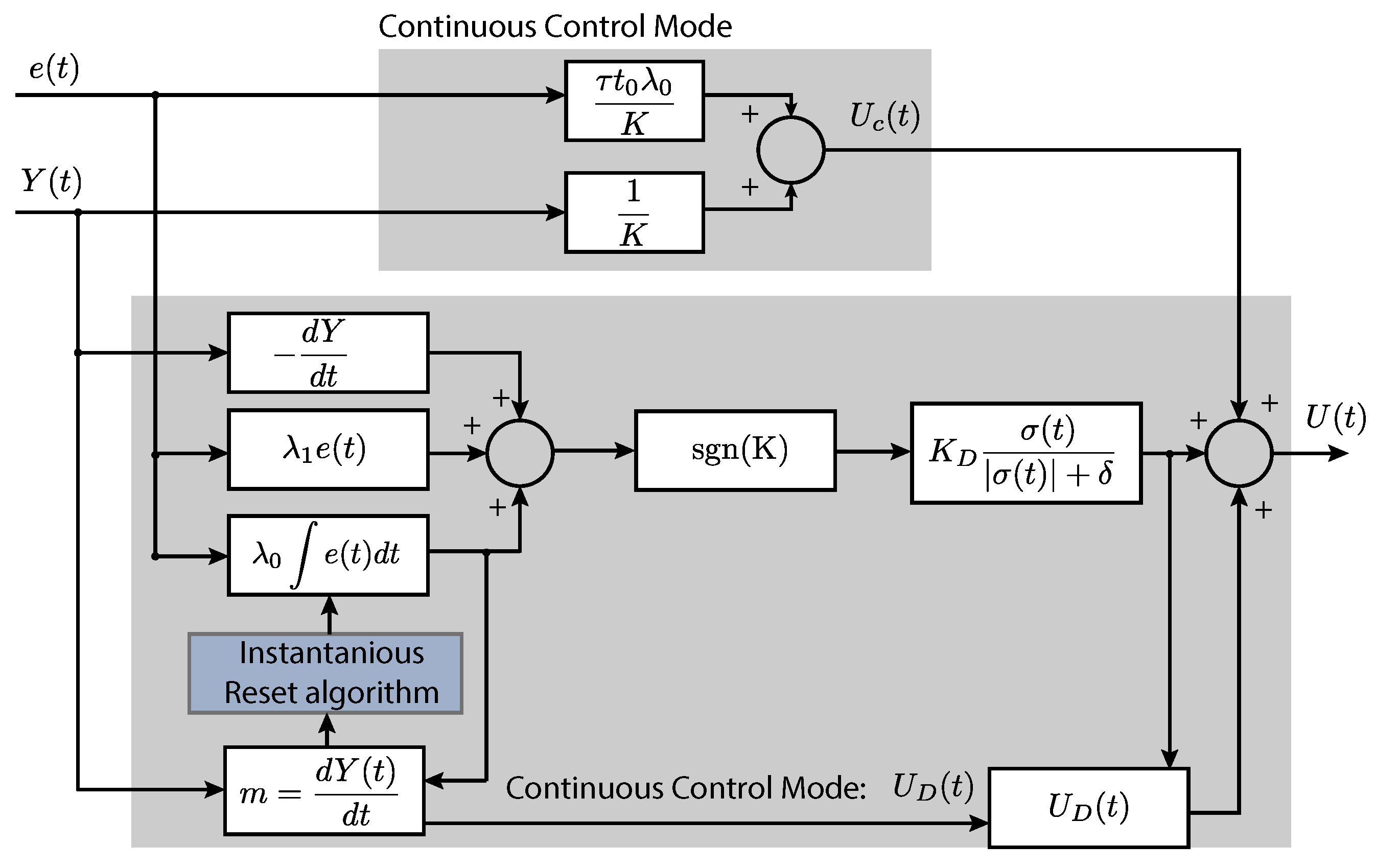
A diagram of the SMC with the proposed WIR approach is shown in Figure 2. Similarly, the proposed WIR strategy is exhibited in Algorithm 1. The SMC with the WIR approach works as follows. At the initial state (see lines 1–2 of Algorithm 1), the control parameters of the SMC controller under test are first tuned and set for required specifications of control performance, including a suitable transitory system response with zero integral control action from a pre-defined sliding surface σ ( t ) . In code line 3, it is computed the saturation overflow s a t 1 between the control output and saturation as the windup resetting conditional. Then, it is also monitored if e ( t ) is within an error margin ± ϵ 1 and also if its derivative has increased within a range ± ϵ 2 to reboot the integral term. Furthermore, it is verified if it only kept working with the SMC in continuous control mode, as presented in pseudo-code lines 4–8 of Algorithm 1. The core of the algorithm is in lines 9–18. Briefly, once the tracking error increase has been detected, the process output derivative is systematically obtained, and it is verified if a value close to zero (see lines 9–12) has been reached. Consequently, if the process output in steady state did not achieve null values (code lines 13–15), the integral term is re-initialized to zero values after verifying if the clamped energy has decayed and, thus, the error is expected to decrease (see line 16). Finally, since the integral term is rebooted to the original conditions, it is necessary to hold the discontinuous control value of the test controller (SMC in this case) to be consistent with the new instantaneous checking of the output derivative, as described in lines 19–20.

3.2. SMC with Windup Conditional Reset

The proposed Windup Conditional Reset (WCR) method is intended to periodically restart the integral control action over longer frames, reducing in this way prompt changes of the sliding surface and monotonous corrections of the integral term in SMC. The WCR will work only under programmed conditions. In particular, rebooting is automatically triggered once the reset action is operation-free and the error keeps increasing boundless. The control framework of SMC-WCR can be seen in Figure 3, while the WCR strategy is detailed in Algorithm 2.
Algorithm 1 Windup Instantaneous Reset—WIR. Anti-windup algorithm to instantaneously reboot the integral control action in an SMC
  1:
Set initial control and model parameters, i.e., K D , δ , λ 0 , λ 1 .
  2:
Set the integrator of the SMC by suppressing previous cumulative values of the sliding mode surface σ ( t ) .
  3:
Compute the saturation overflow s a t 1 between control output and pre-set saturation.
  4:
if | e ( t ) | < ϵ 1 and | d e ( t ) / d t | < ϵ 2 and s a t 1 < ϵ 3  then
  5:
   Maintain monitoring the tracking error e ( t ) .
   (Continuous control mode.)
  6:
else
  7:
   Maintain operating in continuous mode of the SMC.
   (Perform Window Instantaneous Reset.)
  8:
end if
  9:
Compute the output derivative m 1 = d Y d t .
10:
if The process output derivative m 1 differs from zero then
11:
   Maintain verifying the process output derivative.
12:
else
13:
   if The process output in steady-state does not tend to zero then
14:
     Monitor the output slope without restarting the integral control action.
15:
   else
16:
     Reinitialize the integrator to zero in Equation (6). until the clamped energy fully decays.
17:
   end if
18:
end if
19:
Maintain the last discontinuous control value U D .
20:
Go back at the beginning of the WIR algorithm (code line 3).
The operation of Algorithm 2 for the WCR approach is as follows. Analogous to the previous resetting algorithm, the initial conditions of the test controller require to be set; however, it is assumed here an additional variable to account for the number of reboots settled by the operator. The number of reset counts n r is configured to assess the persistence of entering in windup mode (see code line 3 of Algorithm 2). Pseudo-code line 4 is in charge of computing the saturation excess s a t 2 to begin with the windup resetting condition. Lines 5–7 are devoted to verify if the tracking error has increased and if its derivative is within an error speed bounding range ϵ 2 to operate the re-initialization of the integral control action in the discontinuous part of the test controller. Unlike the previous anti-windup algorithm, now it is monitored if the number of reboots n r has not exceeded the counting of resets of the integral control term to prevent the tracking error from being repeatedly reset (see the core of this algorithm in lines 10–23). Then, the reset of the integral control action in the discontinuous control part is conditioned to the number of resets, avoiding in this way the recurrent and unnecessary initialization of the integral control action. Finally, the algorithm is repeated after holding the previous discontinuous control value, as shown in lines 24–25.
Algorithm 2 Windup Conditional Reset—WCR. Anti-windup algorithm to reboot the integrator in a controller by conditionally evaluating the process output derivative
  1:
Set initial parameters an variables of the controller. In this case, K D , δ , λ 0 , λ 1 .
  2:
Configure the integrator in σ ( t ) by initially adjusting zero values.
  3:
Let n r be the reboot counts prescribed by the designer.
  4:
Compute the saturation overflow s a t 2 between the control output and predefined saturation value.
  5:
if  | e ( t ) | < ϵ 1 and | d e ( t ) / d t | < ϵ 2 and s a t 2 < ϵ 3  then
  6:
   Maintain monitoring for the tracking tracking error
   (continuous control mode).
  7:
else
  8:
   Start the Window Conditional Reset
   (discontinuous control mode).
  9:
end if
10:
Compute the process output derivative with m 2 = d Y d t
11:
if The output derivative m 2 does not tend to zero then
12:
   Keep searching for output zero-slope condition on m 2 .
13:
else
14:
   if The process output in steady-state does not tend to zero then
15:
     Monitor the process output derivative without restarting the integral control action.
16:
   else
17:
     if The reset counts do not overpass the number of reboots n r  then
18:
        Monitor the process output derivative m 2 avoiding to tend zero values.
19:
     else
20:
        Reinitialize the integrator to zero in Equation (6) until the clamped energy fully decays.
21:
     end if
22:
   end if
23:
end if
24:
Maintain the last discontinuous control value U D .
25:
Go back at the beginning of the WCR algorithm (code line 4).
Remark 1.
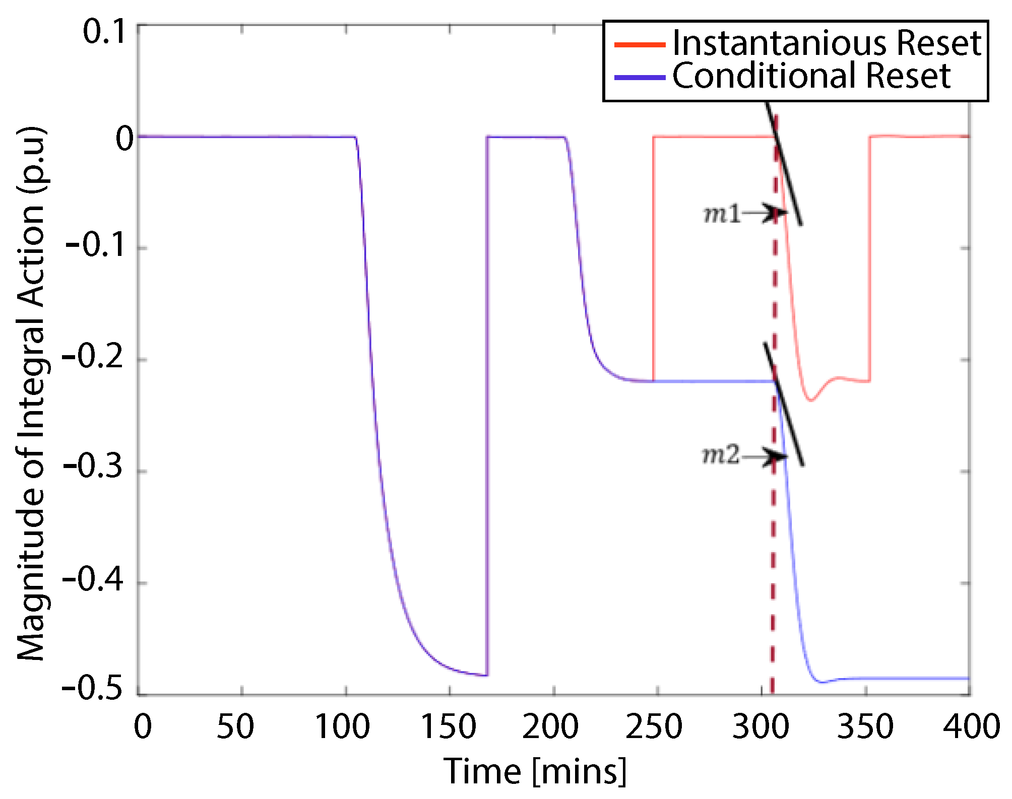
When switching among the anti-windup algorithms, there are changes in the integral term slope of the WCR and WIR, as shown in Figure 4. Note that when the algorithms run for times greater than 300 min, the slope m 1 of the WIR is faster than the slope m 2 for the WCR algorithm, despite the fact that WIR algorithm updates the integration faster than in the WCR; therefore, the computational activity could increase.

4. Modeling of the Mixing Process

This Section presents two process models where the proposed anti-windup algorithms were implemented.

4.1. Mixing Tank Process with Long Time-Delay

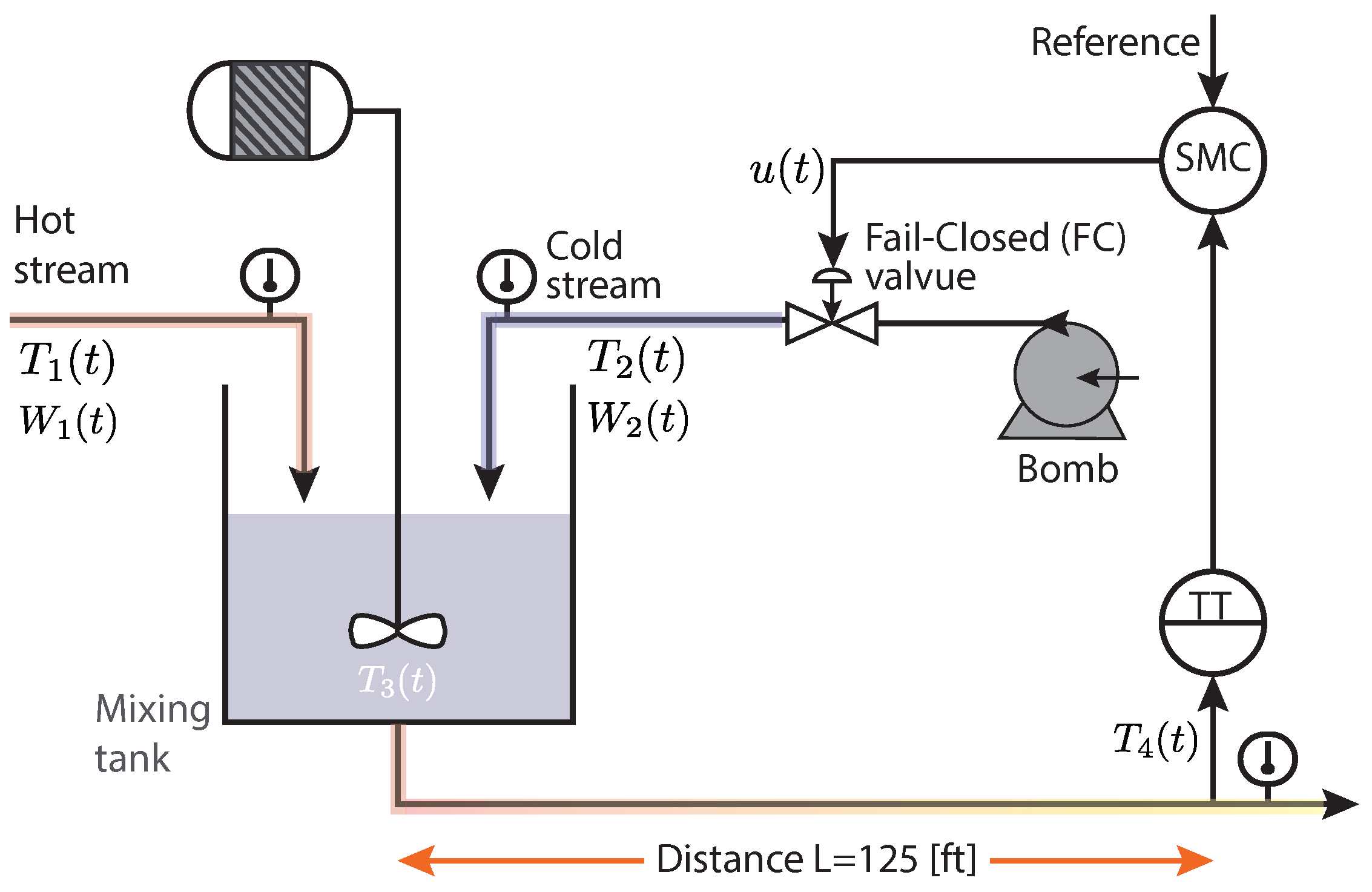
Consider the mixing tank shown in Figure 5, the operation mode consists of the concurrently entering of hot W 1 ( t ) and cold product flow W 2 ( t ) as inputs to the process with temperatures T 1 ( t ) and T 2 ( t ) , respectively. The output T 4 ( t ) is the mixture temperature measured at a point 125 ft downstream from the mixing tank. The Fail-Closed (FC) actuator is in charge of regulating the cold stream to maintain the desired temperature T 3 within the mixing tank.
The control objective consists on maintaining the required mixing temperature T 3 ( t ) (despite disturbances of hot flow W 1 ( t ) ) through the control output u ( t ) of the SMC acting on the FC valve position. In general, the product mixing model considers the following characteristics:
  • The mixing tank and the entire guidance pipe are ideally isolated.
  • The product within the repository is completely homogenized.
  • The TT is calibrated in an operating range [100, 200] ºF.
  • The TT is assumed to provide variations of the process temperature output.
  • The height and volumetric properties of the product inside the mixing tank remain constant during the whole test due to its internal control system.
The mathematical formulation of the process dynamics is based on the principle of energy balance, as follows:
W 1 ( t ) C p 1 ( t ) T 1 ( t ) + W 2 ( t ) C p 2 ( t ) T 2 ( t ) ( W 1 ( t ) + W 2 ( t ) ) × C p 3 ( t ) T 3 ( t ) = V ρ v 3 d T 3 ( t ) d t
where the output temperature T 4 ( t ) , after transporting the product with initial output temperature T 3 ( t ) from the mixing tank towards the location of the transmitter, is given by:
T 4 ( t ) = T 3 ( t t 0 )
where the time-delay t 0 depends on the transport pipe length L, the cross-section of the pipe A, and the hot W 1 and cold W 2 product flow. Then, this time delay can be quantified:
t 0 = L A ρ W 1 ( t ) + W 2 ( t )
where ρ is the density of the mixed product. On the other hand, the output of the temperature transmitter T O ( t ) is represented according to the following system output dynamics:
d T O ( t ) d t = 1 τ T T 4 ( t ) 100 100 T O ( t )
where τ T is the constant time of the temperature sensor. The servo-valve positioning is driven by the controller according to the following equation:
V p ( t ) d t = 1 τ V p m p ( t ) V p
where m p ( t ) is the process input to be controlled. The temperature output after the servo-valve with respect to cold product flow also can be represented by:
W 2 ( t ) = 500 60 C V L V p ( t ) G f Δ P v
where C V L the valve flow coefficient; G f the specified acceleration gravity; and Δ P v the pressure drop across the servo-valve. A complete description of the model parameters in stationary state and the system variables in (12)–(17) can be found in [6,20].
To test the proposed anti-windup algorithms, the FOPDT approximation [20] of the mixing tank described in (12)–(17) was considered. To obtain the reduced order model, the reaction curve procedure is used [39]. Then, by inspection, the necessary gain was found, as well as the time constant and time delay parameters of the FOPDT model as detailed in the transfer function G ( s ) of the process model given by:
G ( s ) = Y ( s ) U ( s ) = 0.81 e 3.14 s 2.29 s + 1
where Y ( s ) U ( s ) is the output/input relation for the FOPDT model of the thermal process under test. The model output is associated with the output temperature T 4 ( t ) , whereas the model input stands for the control variable m ( t ) , which is related to the valve position. The control parameters, on the other hand, were adjusted using experimentation trials and the reaction curve of the system according to the Nelder–Mead method for processes that can be approximated to a delayed first-order system [6]. By doing so, these were the results: λ 0 = 0.14 , λ 1 = 0.50 , K D = 0.75 , and δ = 0.75 .

4.2. Continuous Stirred Tank Reactor Process with Long Time-Delay

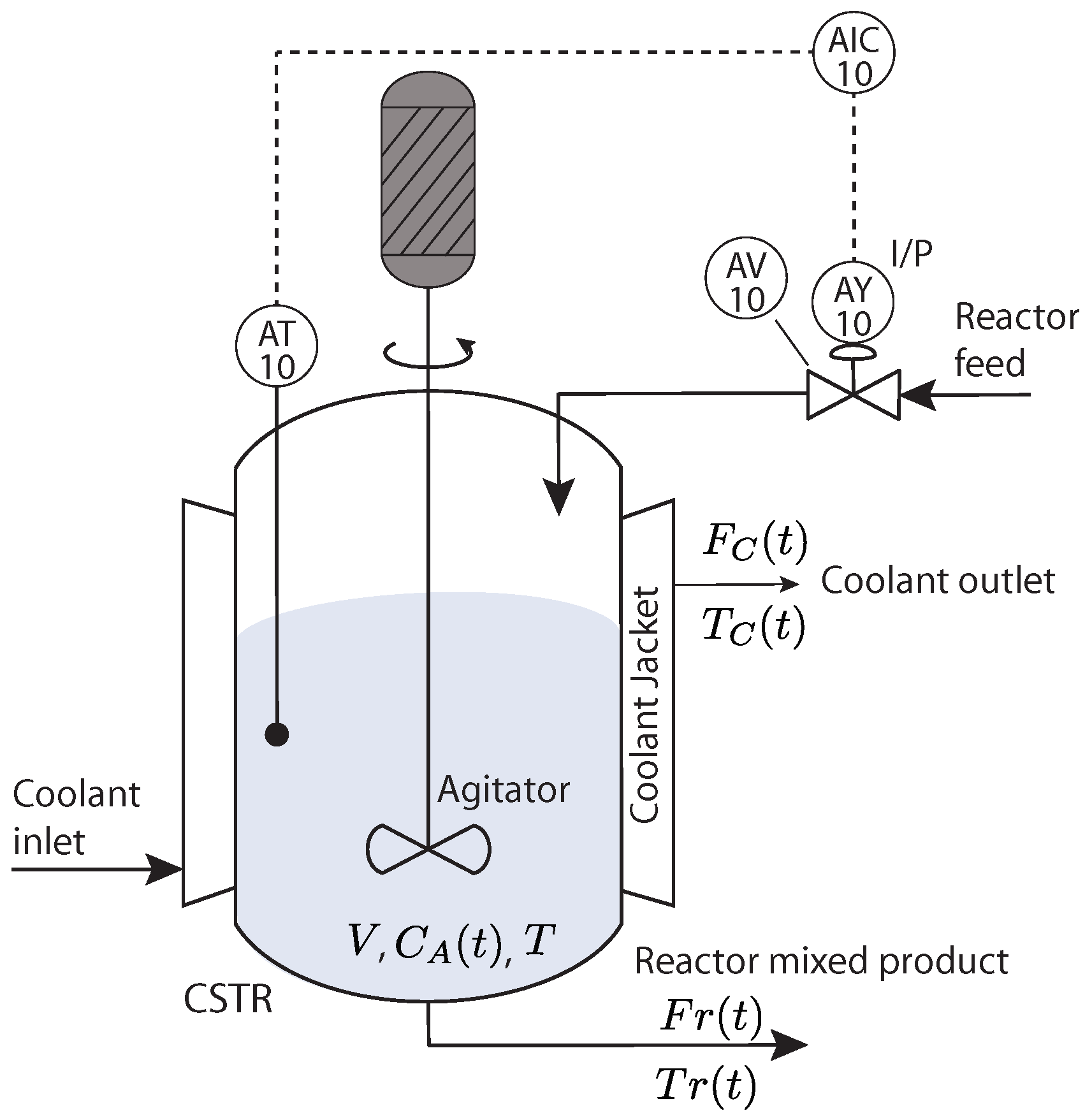
The Continuous Stirred Tank Reactor (CSTR) is used in chemical reaction processes, whose dynamics present an inverse response. The CSTR comprises a stirred tank in which the reaction material and reacted material flow are continuously mixed [40] (see Figure 6). The reactor is covered by a jacket in which a coolant inlet allows to flow of a cooling liquid to maintain the temperature constant and guarantees that the heat produced for the reaction is low. Therefore, the effluent stream contains the same composition as the contents.
For analysis of the system dynamics, the following assumptions were considered:
  • Heat and density capacities of the reactants are constant;
  • The heat loss in a coolant jacket is considered negligible;
  • The reaction heat and volume remain constant;
  • The reaction and reacted material are uniformly mixed.
The mathematical model of the CSTR is obtained based on exothermic reactions according to [41]. A reaction process in a CSTR can be described as follows:
A K 1 B K 2 C
2 A K 3 D
where A K 1 B stands for an exothermic reaction. From mass balance on reactants A and B, the system can be described as follows:
d C A ( t ) d t = F r ( t ) V C A i C A ( t ) k 1 C A ( t ) k 3 C A 2 ( t )
d C B ( t ) d t = F r ( t ) V C B ( t ) + k 1 C A ( t ) = k 2 C B ( t )
Reactor temperature dynamics associated with the energy balance in the jacket:
T c d t = K 1 ( T ( t ) T c ( t ) ) F c ( t ) V ( T c ( t ) T c i ( t ) )
For practical purposes, it should be considered that the control range of the concentration B is from 0 to 1.5714 mol L 1 ; the range of variation of the flow is from 0 to 634.1719 L min 1 . In addition, the transmitter signal y, process input u, and flow through the reactor F r are presented in percentage. The model of the temperature transmitter for the reactor is given by: The sensor–transmitter element takes the form:
d T O ( t ) d t = 1 τ T T ( t ) 80 20 T O ( t )
Similar to the previous model, the CSTR process is characterized by an approximated FOPDT model, and its parameters were obtained with the procedure in [6]. The model in transfer function is given by:
H ( s ) = Y R ( s ) U R ( s ) = 1.66 12.34 s + 1 e 3.16 s
where the output Y R is associated with the reactor temperature and U R represents the control valve position. Variables of the CSTR model are detailed in the Nomenclature Section. The steady-state conditions for each variable of the CSTR process can be found in Table 1. For more details regarding the CSTR model, the reader is referred to [40].

5. Results for the VHMT Process

This Section presents the results of assessing tracking and robust control performance on the VHMT process.

5.1. System Response against Disturbances

This test was performed using six trials to achieve robust performance. The first test was carried out using three control versions, i.e., the SMC per se and the other two with the proposed SMC-WIR and SMC-WCR control strategies. The three remaining trials were carried out with the classical PID controller, including the proposed windup resetting approaches. In all six scenarios, the operating temperature of the product is set to T 3 ( t ) = 15 °F with a stepped decrease variation of hot flow mass W 1 ( t ) acting as disturbance and changing from 250 lb/min to 110 lb/min.
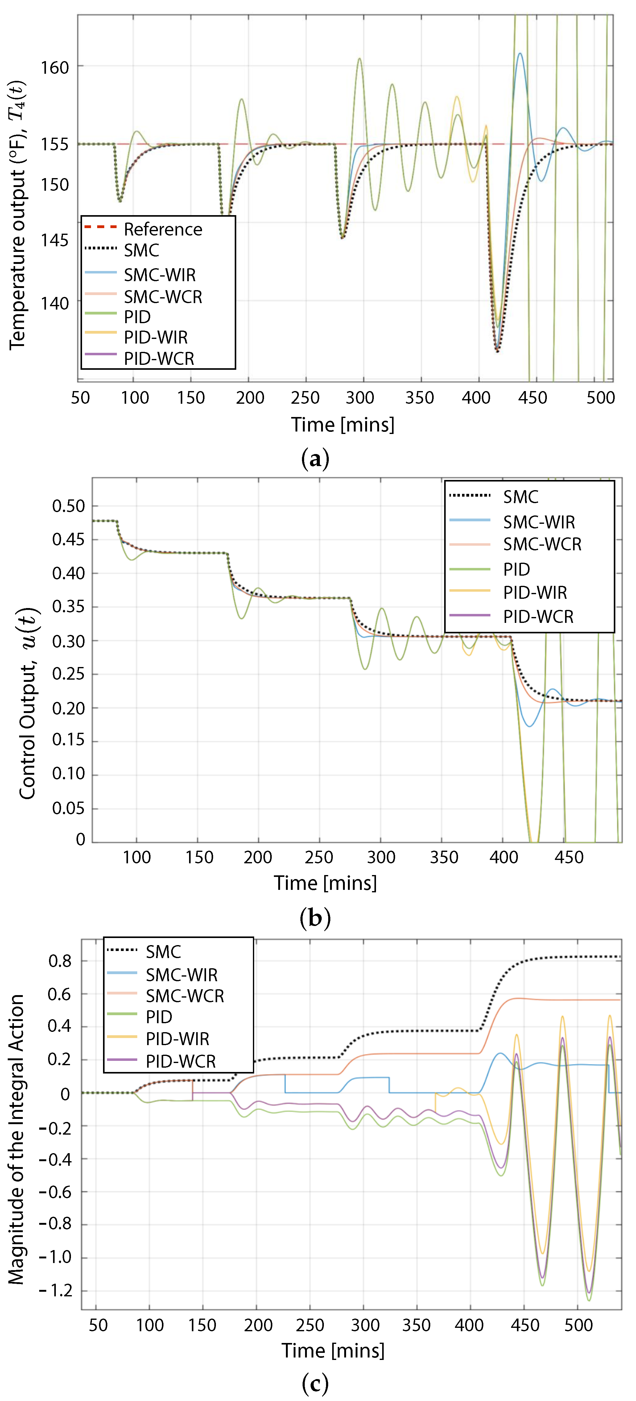
Results of robustness tests are shown in Figure 7, while the system response against hot flow disturbances is presented in Figure 7a. By supervision, the process output is compensated for disturbances through the three versions of the SMC controllers along the whole testing time; however, the settling time and peak response slightly increase in all cases as hot flow temperature decreases while product temperature consequently decreases. The SMC-WIR and SMC-WCR controllers allow the system output to consistently stay on track (at T 4 ( t ) = 150 °F) despite decreasing the hot flow temperature and system dead time. Indeed, the SMC-WCR can provide a system output with a better transient response than the SMC and SMC-WIR controllers. This effect could be possible because of two reasons. First, the reset frequency of the integral action in SMC-WCR is reduced with respect to the other controllers. Second, the integral action for the discontinuous part of the controller is higher than the ones from the other proposed approaches. Indeed, both proposed algorithms work on the sliding mode surface of the SMC controller, but when new disturbances occur, the control output of the SMC-WIR framework becomes faster than the others at expense of larger control input overshoot, as shown in Figure 7b. This increase in the transient of the control action in the SMC-WIR is a result of the integral action updating faster than the ones of the other two controllers.
Both approaches (SMC-WIR and SMC-WCR) enhance the control performance by limiting the magnitude of the integral term of the sliding surface, as shown in Figure 7c. In particular, for the case of SMC-WIR, an increase in the reaction speed can be observed, although it presents a more oscillatory response. Meanwhile, in the SMC-WCR, the evolution of the integrator speed is restricted to avoid consecutively rebooting the integral control action. Then, the discontinuous part of the controller works under the operating limits and the tracking error could not increase unbounded despite the temperature disturbances, counteracting in this way the windup effect while enhancing control performance.
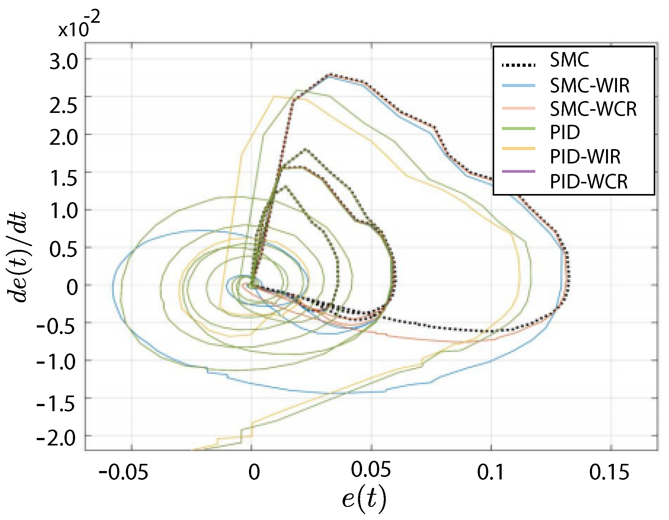
A phase diagram of the error and its derivative is depicted in Figure 8. There it can be observed that the inclusion of the anti-windup algorithm rapidly conducts to error trajectory towards the origin. In particular, the error trajectory of the PID and PID-WIR presented similar response and took common settling behavior, unlike those results obtained with SMC-WCR. The difference between these two responses lies on the ability to counteract disturbances within the control framework, i.e., the common scheme of a PID controller does not allow to directly compensate for disturbances on the discontinuous part, as the case in SMC.
The overall control performance during a 500 min simulation time for each trial is quantified with ISE and ITSE metrics [36] (see Table 2). This Table indicates that the performance of the SMC alone was improved along the trials with the proposed algorithms by mitigating the impact of the windup effect in a 24.35% and 17.05% of the error when using the SMC-WIR and SMC-WCR, respectively. It is worth noticing that this result is hard to reach with common algorithms such as PID, where the ISE is reduced from 2.39 to 2.25 for the best cases (i.e., PID-WIR with respect to PID) [18]. Similarly, based on ITSE when comparing against the SMC, the SMC-WCR has reduced the time spent to overcome the anti-windup effect by 88.7%, while the SMC-WIR approaches by 29.51%.

5.2. System Response against Reference Changes

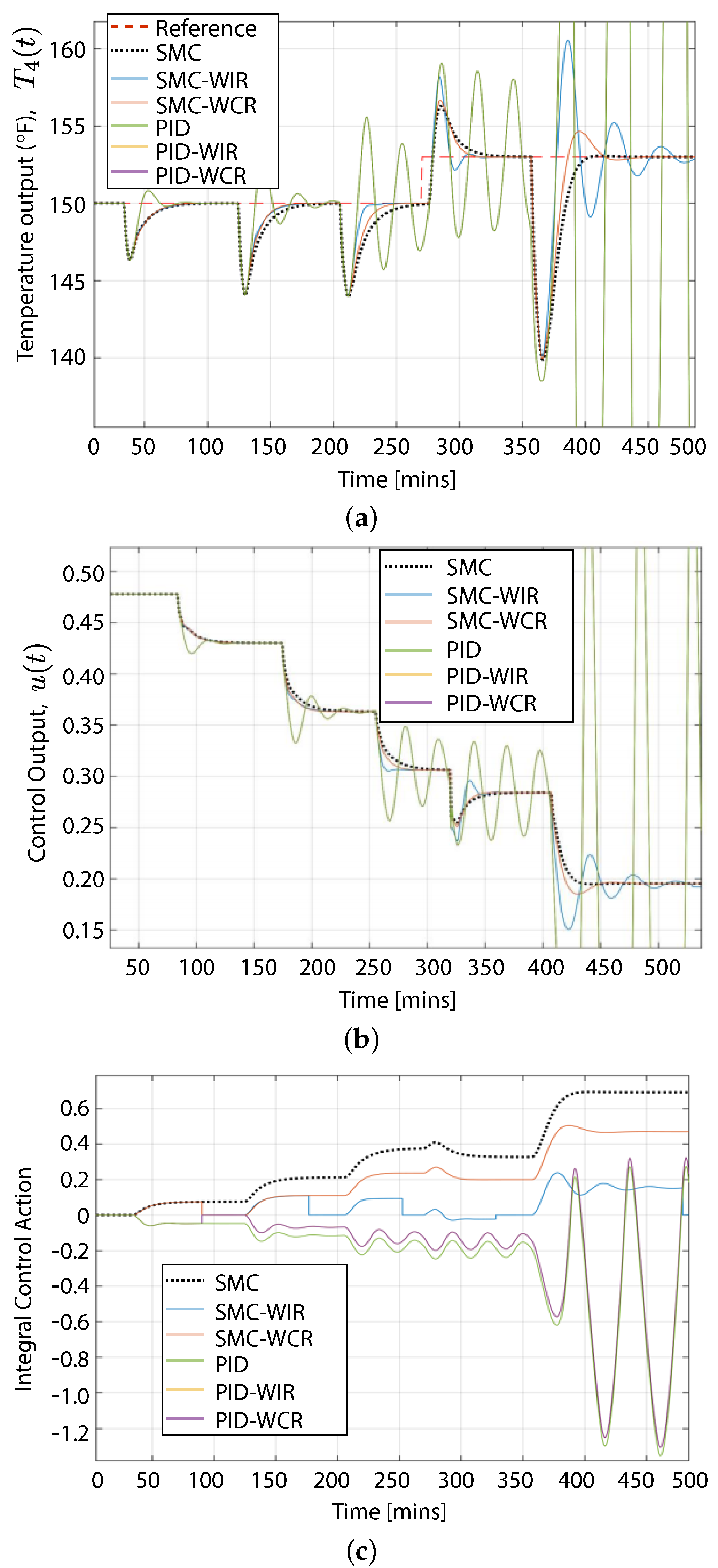
This test consisted in changing the temperature reference in order to assess the control performance when tracking a given trajectory. Similarly, the same six control configurations of the previous experiments have also been considered here. When doing so, besides including variations in the system dynamics with disturbances of hot product flow, the product temperature in the mixing tank was increased by 3 °F for the six scenarios. As shown in Figure 9, the temperature output of the process tracks the reference change set at 270 min in the controllers under test, except for the PID in which an oscillatory response during a long time does not allow to stabilize the process dynamics. For the SMC with both proposed anti-windup approaches, the tracking performance is similar. However, lower peak response and shorter settling time are achieved with the SMC-WCR. Although the reference change does not saturate the servo-valve actuation of the cold product flow, the control action is increased and the temperature output takes longer to reach the steady state. For both proposed anti-windup strategies, the settling time has been reduced since the integral control action has been increased in correspondence with the peak response of the temperature. At this point, it is worth mentioning that the presented anti-windup strategies allow the test controllers, regardless of their control structure, to reduce the impact of the windup effect. Thus, the proposed algorithms comprise an effective approach for integral controllers that seek to shrink the impact of the windup phenomenon.
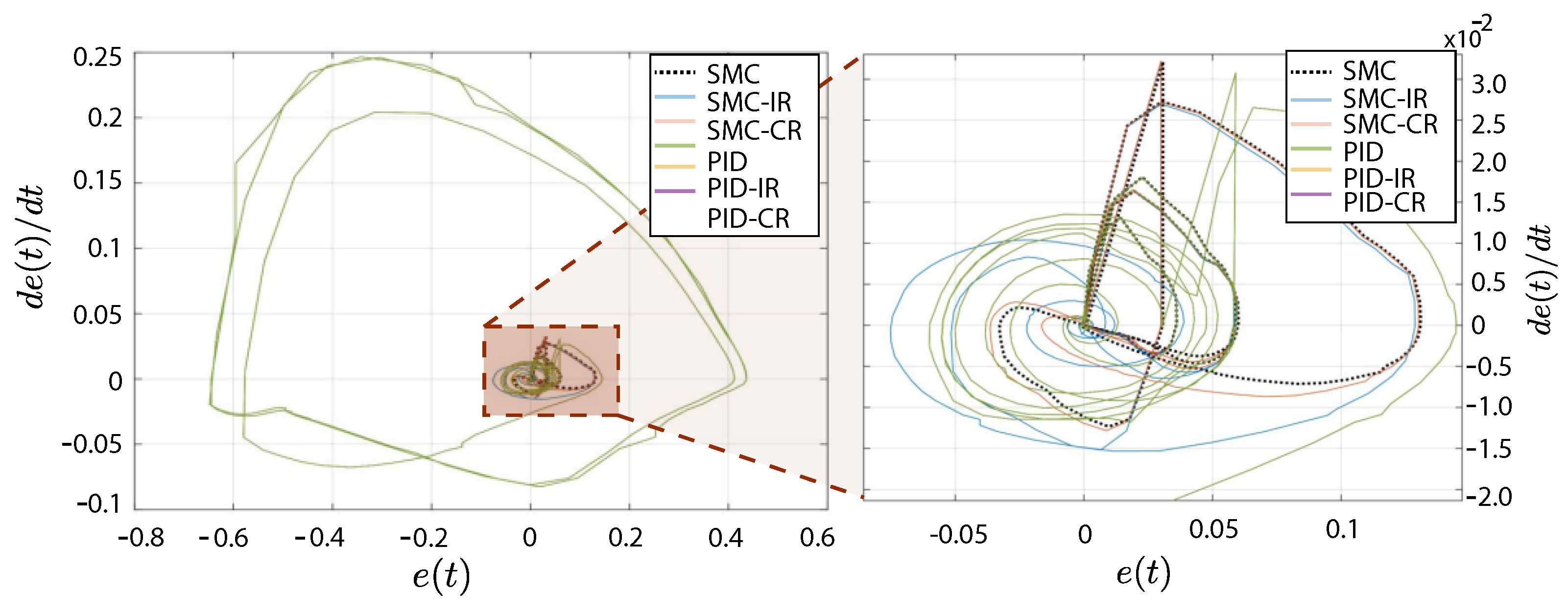
On the other hand, regarding the oscillatory behavior in the system output using the PID strategy with both the WIR and WCR anti-windup algorithms, the trajectory error is longer than those of the SMC-WIR and SMC-WCR as shown in Figure 10. Hence, it is evidenced in the closed-up of Figure 10 that the controller takes shorter time to reach the origin in the SMC-WCR with respect to the SMC since the proposed controller occasionally resets the integral control action and reduces the tracking error only when the anti-windup action is activated.
As in the previous assessment, to quantitatively evaluate the control performance of the test controllers with the proposed anti-windup algorithms under changes of reference, the ISE and ITSE metrics were also considered, as exhibited in Table 3. In general, the control performance of the two test controllers (i.e., SMC-WIR and SMC-WCR) derived in an enhanced performance as expected. Although such improvement is not quite noticeable for the PID controller since the reduction in the ISE is low when compared to the ISE obtained in the SMC with all anti-windup algorithms. Moreover, even though the SMC-WCR has reached lower ISE (5.36%) with respect to the one of the SMC-WIR (25.62%), the SMC-WCR presents a higher reduction in the ITSE (21.31%) than the SMC-WIR (13.83%). This suggests that the integral action allows the controller to mitigate the anti-windup effect faster than the SMC-WIR performs. As the robustness of the PID controller has not improved against disturbances unlike the SMC, the PID controller with any of the proposed algorithms shows a reduction in the tracking error during the trials. Actually, it shows a 0.05% increase in the ISE for the PID-WCR.

6. Results for the CSTR Process

This Section presents the results of assessing tracking and robust control performance on the CSTR process.

6.1. System Response against Disturbances

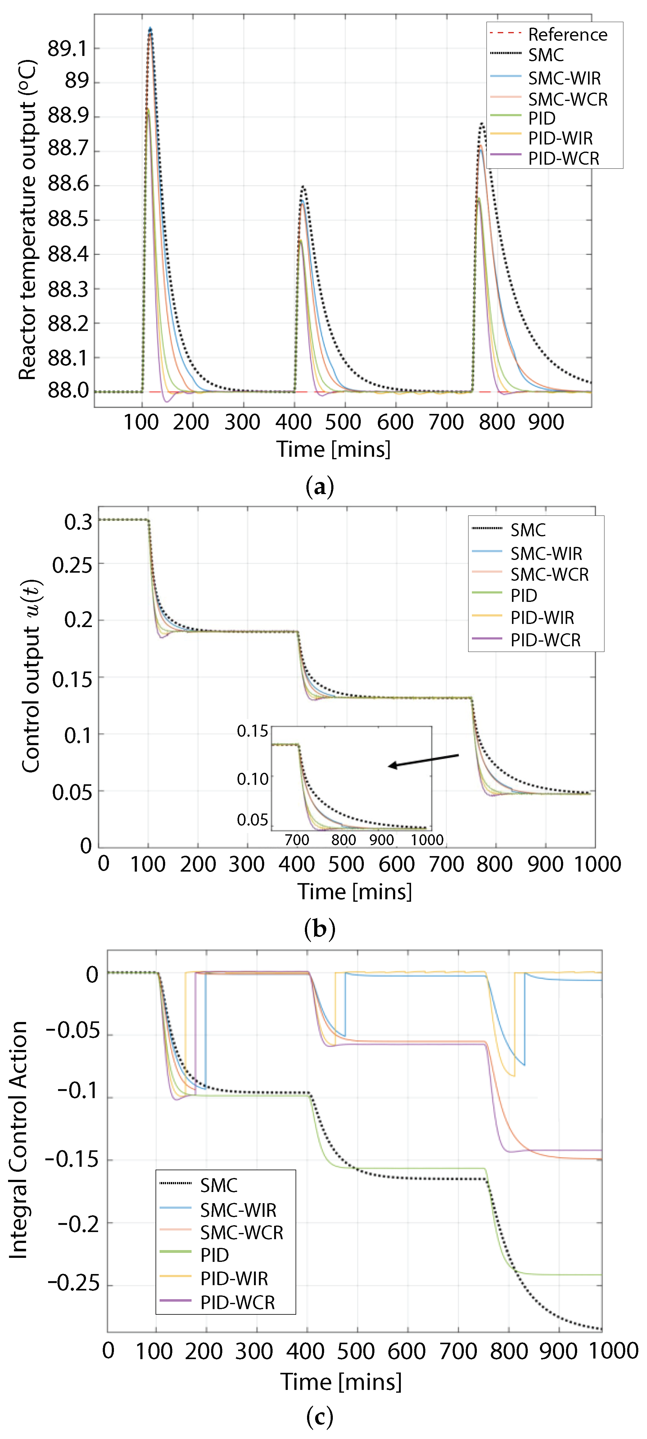
Similar to the previous trials, this test was performed with six trials. Each one of the trials was carried out with the proposed anti-windup algorithms along with the two test controllers. In all six scenarios, the temperature of the flow through the reactor was set to T ( t ) = 88 °C with a coolant temperature increase of 10% acting as an external disturbance.
Figure 11 shows the results obtained for the robustness test. The process output is uniformly compensated for the external disturbances for the three SMC controllers, as shown in Figure 11a. Indeed, The SMC-WIR and SMC-WCR controllers lead the system output to keep the reference temperature of T ( t ) = 88 °C; nevertheless, by inspection, the transient response of the CSTR process when using SMC-WIR is the lowest when compared to the other test controllers. Similarly, the settling time is reduced with the proposed anti-windup techniques, reaching a minimum of 45.7 min and 47.9 min for PID-WCR and SMC-WCR, respectively. Regarding the control output, the control action becomes faster with the two proposed approaches (see Figure 11b) since the integral control action is not cumulatively increasing, as shown in Figure 11c. Unlike the previous test process, the integral control action does not grow unbounded despite the external disturbances because the integral term has been rebooted promptly.
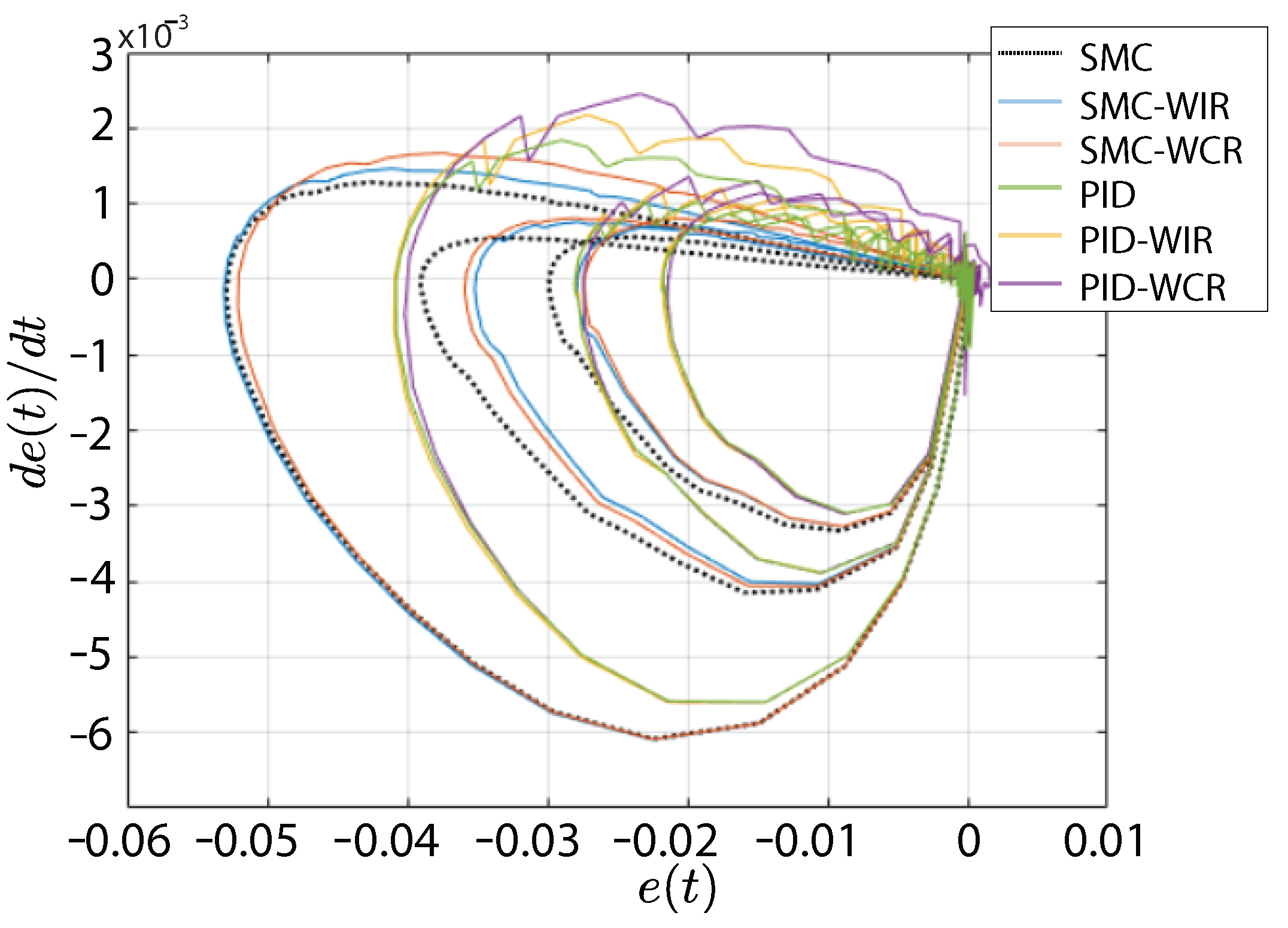
A comparative phase diagram of the tracking error is depicted in Figure 12. This figure presents the error trajectory on which the process variable approaches the temperature reference. Note here that any of the two proposed controllers with the anti-windup algorithms approaches zero due to the integral control action is not cumulative by the continuous and instantaneous reboot action. Nevertheless, the PID-WCR and PID-WIR approach the origin faster than the other proposed SMC controllers.
The overall control performance during a 1000 min simulation time for each trial is quantified with ISE and ITSE metrics [36] (see Table 4). This table shows a performance enhancement with any of the proposed anti-windup algorithms reducing the ISE at 82.57% and 85.22% when using the SMC-WIR and SMC-WCR, respectively. Similarly, the SMC-WIR has reduced the time spent to overcome the anti-windup effect by 26.9%, while the SMC-WIR approach by 33.34%.

6.2. System Response against Reference Changes

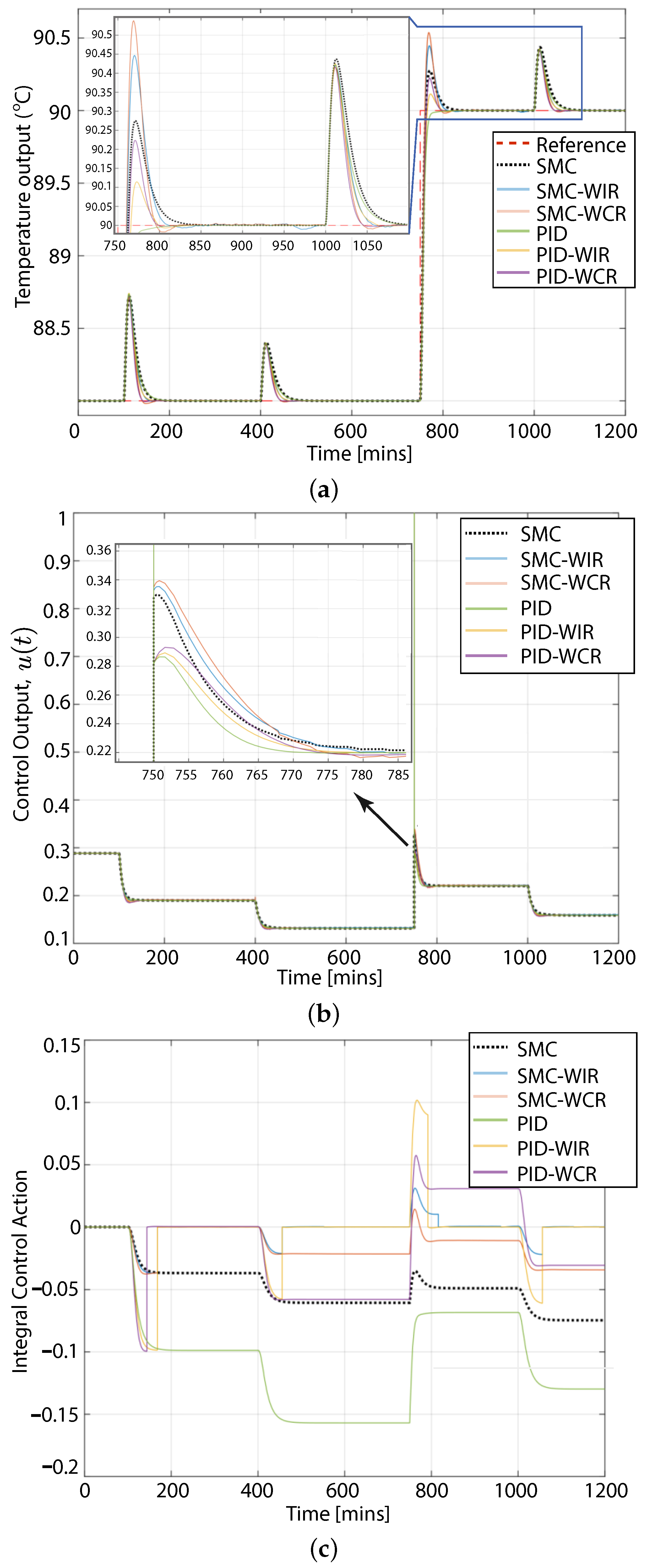
This test consisted on changing the temperature reference to evaluate control performance. By doing so, the reference temperature experienced a step variation from the steady-state value of T ( t ) = 88 °C to 90 °C. As shown in Figure 13, the process output is capable of tracking the new temperature reference; however, different transient responses can be seen for the proposed controllers. For example, the PID controls with any of the anti-windup algorithms approach reduced peak responses when compared to the standard PID alone. Similarly, the amplitude of the temperature output of the reactor is higher with the SMC controller than those of the SMC-WIR and SMC-WCR (see Figure 13a). Regarding the settling time, both proposed WIR and WCR strategies lead the PID and SMC controllers to achieve faster process responses; however, the controllers with instantaneous reset perform faster than those of conditional reset since they operate as soon as the integral error begins to grow unbounded (see Figure 13b). The resetting action is depicted in Figure 13b, where integral control action is rapidly steered to zero with the PID-WIR, PID-WCR, SMC-WIR, and SMC-WCR. Note that this is not the case for the PID and SMC as they remain with zero values after the reference change.
Control performance obtained with ISE and ITSE metrics is briefly included in Table 5. In general, the control performance of the proposed SMC-WIR and SMC-WCR approaches achieved reasonable performance in terms of ISE and ITSE. In particular, the SMC-WIR demonstrated a greater reduction of ISE with respect to its SMC counterparts, i.e., 81.11% with respect to SMC and 73.33 with respect to SMC-WCR. Similar results are obtained with the PID controller. Regarding the ITSE metric, some similar results were obtained for the PID and SMC using both anti-windup algorithms, achieving a reduction of 35.8% average.

7. Conclusions

This work proposed, implemented, and validated two anti-windup algorithms for sliding mode control (SMC) and for typical controllers (i.e., PIDs) found in industrial processes with changing time-delay natures. The results of the experiments demonstrated that the SMC, along with the proposed Windup Instantaneous Reset (SMC-WIR) and Windup Conditional Reset (SMC-WCR) algorithms, can avoid saturation in the actuators with reasonable overshoot and suitable settling time despite disturbances that increase the tracking error. Moreover, robust performance was achieved without loss of system stability. The outcome of SMC, with WCR at the integral control action, presented a smoother system response with respect to SMC-WIR. The proposed anti-windup strategies allowed the SMC to improve the performance up to 15.28% in terms of ISE before saturating actuators in the presence of recurrent disturbances during the experimentation. The SMC-WCR also allowed for experiencing an 84% reduction in the settling time in the ITSE metric, thus implying a faster system response while tracking a changing reference. To summarize, the results evidenced that the proposed algorithms can be implemented without changing the original scheme of test controllers and can reduce the anti-windup effect in SMC control strategies for industrial processes with a long time delay.

Author Contributions

Conceptualization, A.J.P., J.T., and O.C.; Methodology, A.J.P., J.T., and O.C.; Software, J.T. and O.C.; Validation, A.J.P., J.T., and O.C.; Formal analysis, A.J.P. and J.T.; Investigation, A.J.P. and J.T.; Resources, A.J.P., X.D., and O.C.; Data curation, A.J.P. and O.C.; Writing—original draft preparation, A.J.P., J.T., and O.C.; Writing—review and editing, A.J.P. and O.C.; Visualization, A.J.P. and J.T.; Supervision, A.J.P., M.H., and O.C.; Project administration, A.J.P. and O.C.; Funding acquisition, A.J.P. All authors have read and agreed to the published version of the manuscript.

Funding

This research was supported and funded by the Departamento de Ingeniería de Sistemas y Computación with the Universidad Católica del Norte under project 202203010029-VRIDT-UCN. Oscar Camacho thanks the Colegio de Ciencias e Ingenierías, Universidad San Francisco de Quito USFQ, for the supporting given.

Data Availability Statement

Not applicable

Conflicts of Interest

The authors declare no conflict of interest

Nomenclature

The following nomenclature is used in this work:
U D Discontinuous control action
U C Continuous control action.
σ Sliding mode surface.
sgn ( K ) Sign of the control gain K.
K D Tuning gain for discontinuous control.
δ Tuning parameter for discontinuous control.
Y, Y ref Output and reference of the process output, respectively
UProcess control input.
G ( s ) Process model in transfer function of variable s.
τ Time constant of the process (min).
t 0 Time delay of the process (min).
λ 1 , 2 Adjustable parameters of the sliding surface.
± ϵ Allowable tracking error boundary.
mDerivative of the process output.
s a t Anti-windup saturation function.
W 1 , 2 Hot and cold product flow, respectively, (lb/min).
T 1 , 2 Hot and cold stream temperature, respectively, (°C).
T 4 , 3 Temperature of the process output with and without delay (°C).
C p Stream heat capacity at constant pressure, Btu/lb−°F.
C v Stream heat capacity at constant volume (Btu/lb−°F).
ρ Density of the mixing tank content in lb/ft 3 .
A 3 Cross section of the mixing tank (ft 2 ).
h 3 Product level in the mixing tank (ft).
C V L 3 Manual valve flow coefficient (gpm/ft 1 / 2 ).
C V L Control valve flow coefficient in (gpm/psi 1 / 2 ).
V ( p ) Valve position from 0 (valve closed) to 1 (valve open).
T O Output signal of the temperature transmitter (0 to 1 p.u).
m p Mass of the process to control (0 to 1 p.u).
G f Specific gravity, dimensionless.
Δ P v Pressure loss through the control valve (psi).
τ V p Control valve time constant (min).
ACross section of the transportation pipe (ft 2 ).
LLength of the transportation pipe (ft).
F r Flow through the reactor (m 3 /min)
VReactor volume that will remain constant during operation (m 3 )
C A , B Concentration of A or B in the reactor (mol L 1 )
C A o , B o Concentration of A o or B o in steady-state (mol L 1 )
F c Coolant flow (m 3 /s)
T O ( t ) Normalized output signal of the transmitter (0 to 1 p.u)
T c Coolant temperature (°C).
k i ( i = 1 , 2 , 3 ) Reaction rate constants for three reactions.

References

  1. Mejía, C.; Salazar, E.; Camacho, O. A comparative experimental evaluation of various Smith predictor approaches for a thermal process with large dead time. Alex. Eng. J. 2022, 61, 9377–9394. [Google Scholar] [CrossRef]
  2. Yan, H.; Zhou, X.; Zhang, H.; Yang, F.; Wu, Z.-G. A Novel Sliding Mode Estimation for Microgrid Control With Communication Time Delays. IEEE Trans. Smart Grid 2019, 10, 1509–1520. [Google Scholar] [CrossRef]
  3. Liu, Z.X.; Wang, Z.Y.; Wang, Y.; Ji, Z.-C. Optimal Zonotopic Kalman Filter-based State Estimation and Fault-diagnosis Algorithm for Linear Discrete-time System with Time Delay. Int. J. Control Autom. Syst. 2022, 20, 1757–1771. [Google Scholar] [CrossRef]
  4. Qi, X.; Liu, W.; Lu, J. Observer-based Finite-time Adaptive Prescribed Performance Control for Nonlinear Systems with Input Delay. Int. J. Control Autom. Syst. 2022, 20, 1428–1438. [Google Scholar] [CrossRef]
  5. Camacho, O.; Leiva, H. Impulsive semilinear heat equation with delay in control and in state. Asian J. Control 2020, 22, 1075–1089. [Google Scholar] [CrossRef]
  6. Espín, J.; Castrillon, F.; Leiva, H.; Camacho, O. A modified Smith predictor based-sliding mode control approach for integrating processes with dead time. Alex. Eng. J. 2022, 61, 10119–10137. [Google Scholar] [CrossRef]
  7. Mancisidor, I.; Pena-Sevillano, A.; Dombovari, Z.; Barcena, R.; Munoa, J. Delayed feedback control for chatter suppression in turning machines. Mechatronics 2019, 63, 102276. [Google Scholar] [CrossRef]
  8. Gao, F.; Chen, W. Disturbance Rejection in Singular Time-delay Systems with External Disturbances. Int. J. Control Autom. Syst. 2022, 20, 1841–1848. [Google Scholar] [CrossRef]
  9. Cajamarca, B.; PatiñO, K.; Camacho, O.; Chavez, D.; Leica, P.; Pozo, M. A comparative analysis of sliding mode controllers based on internal model for a nonminimum phase buck and boost converter. In Proceedings of the 2019 International Conference on Information Systems and Computer Science (INCISCOS), Quito, Ecuador, 20–22 November 2019; pp. 189–195. [Google Scholar] [CrossRef]
  10. Salinas, L.R.; Santiago, D.; Slawiñski, E.; Mut, V.; Chavez, D.; Leica, P.; Camacho, O. P+ d plus sliding mode control for bilateral teleoperation of a mobile robot. Int. J. Control Autom. Syst. 2018, 16, 1927–1937. [Google Scholar] [CrossRef]
  11. Báez, E.; Bravo, Y.; Leica, P.; Chávez, D.; Camacho, O. Dynamical sliding mode control for nonlinear systems with variable delay. In Proceedings of the 2017 IEEE 3rd Colombian Conference on Automatic Control (CCAC), Cartagena, Colombia, 18–20 October 2017; pp. 1–6. [Google Scholar] [CrossRef]
  12. Owais, K.; Mahmood, P.; Ejaz, A.; Jamshed, I. On the derivation of novel model and sophisticated control of flexible joint manipulator. Rev. Roum. Sci. Tech.-Ser. Electrotech. Energ. 2017, 62, 103–108. [Google Scholar]
  13. Prado, A.J.; Cheein, F.A.; Torres-Torriti, M. Probabilistic approaches for self-tuning path tracking controllers using prior knowledge of the terrain. In Proceedings of the 2016 IEEE/RSJ International Conference on Intelligent Robots and Systems (IROS), Daejeon, Republic of Korea, 9–14 October 2016; pp. 3095–3100. [Google Scholar] [CrossRef]
  14. Wu, X.; Lin, Z. On Immediate, Delayed and Anticipatory Activation of Anti-Windup Mechanism: Static Anti-Windup Case. IEEE Trans. Autom. Control 2012, 57, 771–777. [Google Scholar] [CrossRef]
  15. Peng, Y.; Vrancic, D.; Hanus, R. Anti-windup, bumpless, and conditioned transfer techniques for PID controllers. IEEE Control Syst. Mag. 1996, 16, 48–57. [Google Scholar] [CrossRef]
  16. Chen, L.; Fang, J. Adaptive Continuous Sliding Mode Control for Fractional-order Systems with Uncertainties and Unknown Control Gains. Int. J. Control Autom. Syst. 2022, 20, 1509–1520. [Google Scholar] [CrossRef]
  17. Iqbal, J. Modern Control Laws for an Articulated Robotic Arm: Modeling and Simulation. Eng. Technol. Appl. Sci. Res. 2019, 9, 4057–4061. [Google Scholar] [CrossRef]
  18. Herrera, M.; Morales, L.; Rosales, A.; Garcia, Y.; Camacho, O. Processes with variable dead time: Comparison of hybrid control schemes based on internal model. In Proceedings of the 2017 IEEE Second Ecuador Technical Chapters Meeting (ETCM), Salinas, Ecuador, 16–20 October 2017; pp. 1–6. [Google Scholar] [CrossRef]
  19. Prado, J.; Yandun, F.; Torres Torriti, M.; Auat Cheein, F. Overcoming the Loss of Performance in Unmanned Ground Vehicles Due to the Terrain Variability. IEEE Access 2018, 6, 17391–17406. [Google Scholar] [CrossRef]
  20. Torres, J.; Chavez, D.; Aboukheir, H.; Herrera, M.; Prado, J.; Camacho, O. Anti-Windup Algorithms for Sliding Mode Control in Processes with Variable Dead-Time. In Proceedings of the 2020 IEEE ANDESCON, Quito, Ecuador, 13–16 October 2020; pp. 1–6. [Google Scholar] [CrossRef]
  21. Camacho, O.; Díaz, R.; Obando, C. Hardware in the loop simulation for sliding mode control schemes for deadtime systems. In Proceedings of the International Conference on Information Systems and Computer Science (INCISCOS), Quito, Ecuador, 20–22 November 2019; pp. 183–188. [Google Scholar] [CrossRef]
  22. Aichi, B.; Bourahla, M.; Kendouci, K. Real-Time Hybrid Control of Induction Motor Using Sliding Mode and PI Anti-Windup. In Proceedings of the 2018 International Conference on Electrical Sciences and Technologies in Maghreb (CISTEM), Algiers, Algeria, 28–31 October 2018; pp. 1–6. [Google Scholar] [CrossRef]
  23. Guo, X.-G.; Ahn, C.K. Adaptive Fault-Tolerant Pseudo-PID Sliding-Mode Control for High-Speed Train with Integral Quadratic Constraints and Actuator Saturation. IEEE Trans. Intell. Transp. Syst. 2021, 22, 7421–7431. [Google Scholar] [CrossRef]
  24. Zhang, X.; Su, C. Stability Analysis and Antiwindup Design of Switched Linear Systems with Actuator Saturation. Int. J. Control Autom. Syst. 2018, 16, 1247–1253. [Google Scholar] [CrossRef]
  25. Zhao, D.; Wang, Y.; Xu, L.; Wu, H. Adaptive Robust Control for a Class of Uncertain Neutral Systems with Time Delays and Nonlinear Uncertainties. Int. J. Control Autom. Syst. 2021, 19, 1215–1227. [Google Scholar] [CrossRef]
  26. Prusty, S.B.; Seshagiri, S.; Pati, U.C.; Mahapatra, K.K. Sliding mode control of coupled tank systems using conditional integrators. IEEE/CAA J. Autom. Sin. 2020, 7, 118–125. [Google Scholar] [CrossRef]
  27. Sun, T.; Liu, C.; Wang, X. Anti-windup neural network-sliding mode control for dynamic positioning vessels. In Proceedings of the 2021 8th International Conference on Information, Cybernetics, and Computational Social Systems (ICCSS), Beijing, China, 10–12 December 2021; pp. 356–361. [Google Scholar] [CrossRef]
  28. Scholl, T.H.; Groll, L. Stability Criteria for Time-Delay Systems from an Insightful Perspective on the Characteristic Equation. IEEE Trans. Autom. Control, 2022; ahead of print. [Google Scholar] [CrossRef]
  29. Sajjadi-Kia, S.; Jabbari, F. Modified Anti-windup compensators for stable plants: Dynamic Anti-windup case. In Proceedings of the 48h IEEE Conference on Decision and Control (CDC) held jointly with 2009 28th Chinese Control Conference, Shanghai, China, 15–18 December 2009; pp. 2795–2800. [Google Scholar] [CrossRef]
  30. Camacho, O.; Smith, C. Sliding mode control: An approach to regulate nonlinear chemical processes. ISA Trans. 2000, 39, 205–218. [Google Scholar] [CrossRef]
  31. Nath, K.; Bera, M.K. Adaptive Integral Sliding Mode Control: An Event-Triggered Approach. IFAC-PapersOnLine 2022, 55, 604–609. [Google Scholar] [CrossRef]
  32. Nath, U.M.; Dey, C.; Mudi, R.K. Designing of anti-windup feature for internal model controller with real-time performance evaluation on temperature control loop. In Proceedings of the 2019 2nd International Conference on Intelligent Computing, Instrumentation and Control Technologies (ICICICT), Kannur, India, 5–6 July 2019; pp. 787–790. [Google Scholar] [CrossRef]
  33. Bandyopadhyay, B.; Deepak, F.; Park, Y.J. A Robust Algorithm Against Actuator Saturation using Integral Sliding Mode and Composite Nonlinear Feedback. IFAC Proc. Vol. 2008, 41, 14174–14179. [Google Scholar] [CrossRef] [Green Version]
  34. Septanto, H.; Syaichu-Rohman, A.; Mahayana, D. Static anti-windup compensator design of linear Sliding Mode Control for input saturated systems. In Proceedings of the 2011 International Conference on Electrical Engineering and Informatics, Bandung, Indonesia, 17–19 July 2011; pp. 1–4. [Google Scholar] [CrossRef]
  35. Guanghui, Z.; Huihe, S. Anti-windup design for the controllers of integrating processes with long delay. J. Syst. Eng. Electron. 2007, 18, 297–303. [Google Scholar] [CrossRef]
  36. Proaño, P.; Capito, L.; Rosales, A.; Camacho, O. Sliding Mode Control: Implementation Like PID for Trajectory-Tracking for Mobile Robots. In Proceedings of the 2015 Asia-Pacific Conference on Computer Aided System Engineering, Quito, Ecuador, 14–16 July 2015; pp. 220–225. [Google Scholar] [CrossRef]
  37. Coronel, W.; Camacho, O. A Dynamic Sliding Mode Controller using a Rotating Type Moving Sliding Surface for Chemical Processes with Variable Delay. In Proceedings of the 2021 IEEE CHILEAN Conference on Electrical, Electronics Engineering, Information and Communication Technologies (CHILECON), Valparaiso, Chile, 6–9 December 2021; pp. 1–6. [Google Scholar] [CrossRef]
  38. Utkin, V.; Poznyak, A.; Orlov, Y.V.; Polyakov, A. Road Map for Sliding Mode Control Design; Springer: Cham, Switzerland, 2020. [Google Scholar] [CrossRef]
  39. Smith, C.; Corripio, A.B. Principles and Practices of Automatic Process Control, 3rd ed.; Wiley: Hoboken, NJ, USA, 2005; ISBN 978-0-471-43190-9. [Google Scholar]
  40. Dogu, T.; Dogu, G. Fundamentals of Chemical Reactor Engineering: A Multi-Scale Approach; John Wiley & Sons: Hoboken, NJ, USA, 2021. [Google Scholar]
  41. Victor, M.A.; Pedro, B.; Orlando, A. Robustness Considerations on PID Tuning for Regulatory Control of Inverse Response Processes. IFAC Proc. Vol. 2012, 45, 193–198. [Google Scholar] [CrossRef]
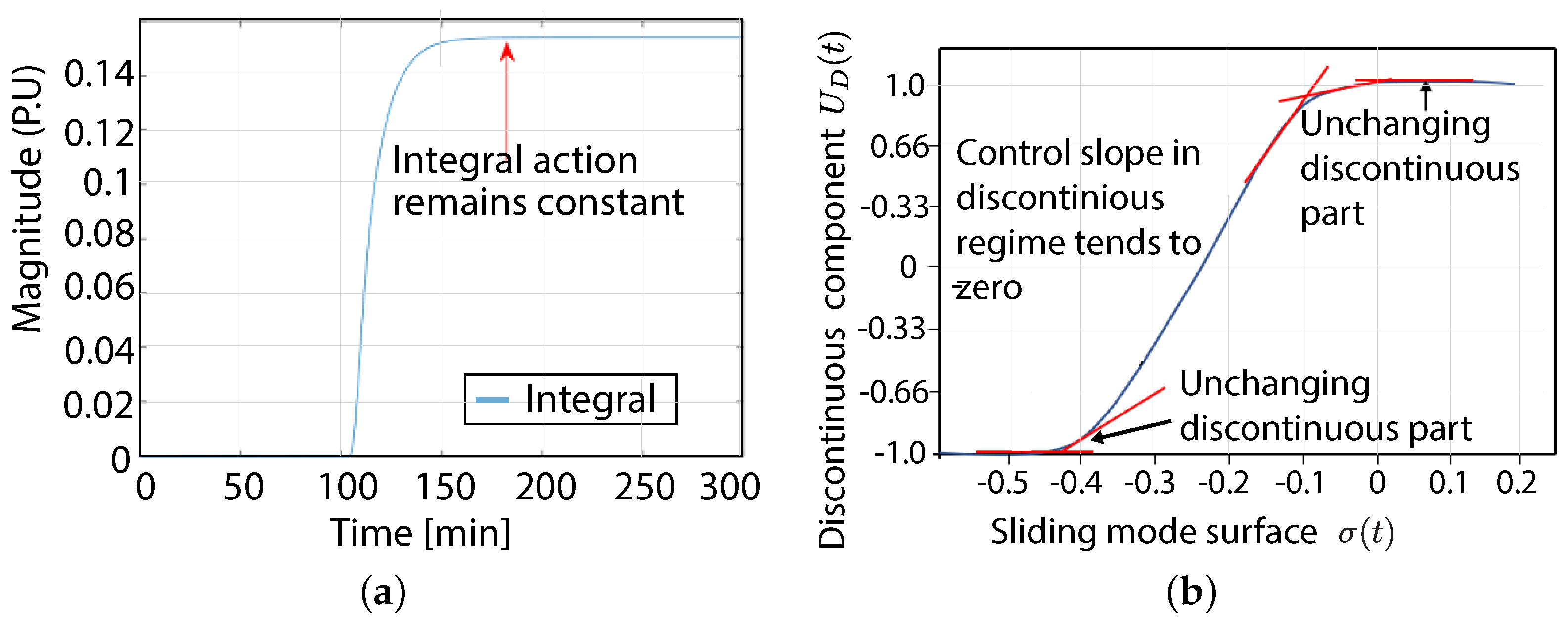
Figure 1. Effect of integral control saturation on the discontinuous part of SMC. (a) shows that, as the slope is close to zero, the error integral in the sliding surface does not grow unbounded, enabling the controller to counteract the windup effect. (b) shows as the output slope U D ( t ) tends to be null as a particular value of σ ( t ) is reached. (a) Evolution of the integral control action in discontinuous mode. (b) Discontinuous control output with respect to the sliding mode surface σ .
Electronics 11 04220 g001
Figure 2. General scheme of the proposed SMC-WIR method.
Electronics 11 04220 g002
Figure 3. General scheme of the proposed SMC-WCR method.
Electronics 11 04220 g003
Figure 4. Evolution of the integrator slope on the sliding surface in instantaneous and conditional reset.
Electronics 11 04220 g004
Figure 5. Mixing Tank Process. An SMC controller receives temperature measurements T 4 ( t ) of the mixing tank through the Temperature Transmitter (TT). The control output u ( t ) is applied to a Fail-Closed (FC) typed servo-valve so that regulates the output temperature of the product with cold flow input T 2 ( t ) . Hot flow disturbs the system temperature, whereas the temperature output and process delay depend on the distance between the mixing tank and TT.
Electronics 11 04220 g005
Figure 6. Continuous Stirred Tank Reactor—CSTR.
Electronics 11 04220 g006
Figure 7. Robustness test. Process response using the proposed anti-windup algorithms for different control strategies against systematic disturbances acting on a mixing tank process (see (a)). It is noticeable how the control action for the SMC-WIR and SMC-WCR is increased as much as the hot flow disturbance impacts the output stream temperature (see (b)). By inspection, the integral action of the SMC-WIR is the one that increases the least, generating a suitable condition to avoid the tracking error accumulation (see (c)). (a) Process temperature output. (b) Control output against disturbances. (c) Evolution of integral control action.
Electronics 11 04220 g007
Figure 8. Phase diagram of the error derivative for the two test controllers and the two proposed windup correction strategies on the mixing tank process.
Electronics 11 04220 g008
Figure 9. Tracking performance test. Process response using the anti-windup algorithms for different control strategies against reference changes of product temperature on a mixing tank process. (a) Process temperature output. (b) Control output against disturbances. (c) Evolution of integral control action.
Electronics 11 04220 g009
Figure 10. Closed-up of the phase diagram for the derivative of the tracking error comparing the two test controllers with the two proposed anti-windup strategies on the mixing tank process.
Electronics 11 04220 g010
Figure 11. Robustness test for the CSTR process. (a) shows the regulation response against coolant temperature disturbances. The control actions for the SMC-WIR and SMC-WCR are increased as much as the disturbance impacts reactor temperature (see (b)). By inspection, the integral control actions of SMC-WCR and SMC-WIR remain fixed as the tracking error is accumulated over time (see (c)). (a) Process temperature output. (b) Control output against disturbances. (c) Evolution of integral control action.
Electronics 11 04220 g011
Figure 12. A comparative phase diagram of the error derivative for the proposed windup correction strategies on the CSTR process.
Electronics 11 04220 g012
Figure 13. Tracking performance test. Responses of the CSTR process using the anti-windup algorithms for different control strategies against reference changes. (a) Process temperature output. (b) Control output against disturbances. (c) Evolution of integral control action.
Electronics 11 04220 g013
Table 1. Initial values of the continuous stirred reactor tank.
Model ParametersValuesUnits
k 1 5 / 6 min 1
k 2 5 / 3 min 1
k 3 1 / 6 L . mol 1 . min 1
C A i 10 mol L 1
V700L
C A o 2.9175 mol L 1
C B o 1.1 mol L 1
u o % 60%
Table 2. Outcome of robustness tests on the VHMT process by comparing performance in terms of ISE and ITSE.
ISEITSEVariation of ISE
(Percentage)
Variation of ITSE
(Percentage)
SMC0.35795.454--
SMC-WIR0.27067.34324.35%
(of reduction)
29.51%
(of reduction)
SMC-WCR0.30279.30117.05%
(of reduction)
88.7%
(of reduction)
PID2.394933.536--
PID-WIR2.259933.235532.77%
(of increase)
497.18%
(of increase)
PID-WCR2.569935.781619.19%
(of increase)
548.06%
(of increase)
Table 3. Outcome of trajectory tracking tests from different SMC approaches on the VHMT process by comparing control performance in terms of ISE and ITSE.
ISEITSEVariation of ISE
(Percentage)
Variation of ITSE
(Percentage)
SMC0.56161.34--
SMC-WIR0.41139.0227.78%
(of reduction)
13.83%
(of reduction)
SMC-WCR0.53143.085.36%
(of reduction)
21.31%
(of reduction)
PID23.661166.08--
PID-WIR23.641155.660.05%
(of reduction)
0.89%
(of reduction)
PID-WCR23.691160.730.05%
(of increase)
0.45%
(of reduction)
Table 4. Outcome of robustness tests on the CSTR process by comparing performance in terms of ISE and ITSE.
ISEITSEVariation of ISE
(Percentage)
Variation of ITSE
(Percentage)
SMC0.786139.111--
SMC-WIR0.137101.55782.57%
(of reduction)
26.99%
(of reduction)
SMC-WCR0.12492.73684.22%
(of reduction)
3.34%
(of reduction)
PID0.86795.188--
PID-WIR0.81589.52810.31%
(of increase)
35.64%
(of reduction)
PID-WCR0.60385.90123.28%
(of reduction)
38.25%
(of reduction)
Table 5. Outcome of trajectory tracking tests from different SMC approaches on the CSTR process by comparing control performance in terms of ISE and ITSE.
ISEITSEVariation of ISE
(Percentage)
Variation of ITSE
(Percentage)
SMC0.9128.22--
SMC-WIR0.1778.1881.11%
(of reduction)
39.03%
(of reduction)
SMC-WCR0.2483.2173.33%
(of reduction)
35.10%
(of reduction)
PID0.3399.76--
PID-WIR0.2187.9176.67%
(of reduction)
31.44%
(of reduction)
PID-WCR0.3889.2657.78%
(of reduction)
30.39%
(of reduction)
Publisher’s Note: MDPI stays neutral with regard to jurisdictional claims in published maps and institutional affiliations.