Article

Design of Open-Ended Structure Wideband PCB Rogowski Coil Based on New Winding Method

1
College of Mechanical and Electrical Engineering, Kunming University of Science and Technology, Kunming 650504, China
2
Electric Power Research Institute, Yunnan Power Grid Co., Ltd., Kunming 650217, China
3
College of Science, Kunming, University of Science and Technology, Kunming 650504, China
*
Author to whom correspondence should be addressed.
Electronics 2022, 11(3), 381; https://doi.org/10.3390/electronics11030381
Submission received: 10 December 2021 / Revised: 21 January 2022 / Accepted: 24 January 2022 / Published: 27 January 2022
(This article belongs to the Section Power Electronics)

Abstract

:
Compared with the traditional Rogowski coil, printed circuit board (PCB) Rogowski coil has the advantages of high measurement accuracy, simple manufacturing process and low cost. It has become an important device in current measurement. However, the existing PCB Rogowski coils are mostly closed, and the open-ended structure PCB Rogowski coils are susceptible to external magnetic field interference. This paper proposes an open-ended structure PCB Rogowski coil based on a new winding method, so that the two open-ended PCB Rogowski coils are evenly distributed when closed, while improving the coil’s immunity to external magnetic fields based on the winding method of equal area of the de-wired and loop. In addition, this paper uses the hybrid integration circuit and the back-end matching method to achieve the broadband measurement performance of the sensor. Finally, the experimental results show that the mutual inductance difference between the closed and open-ended structure PCB Rogowski coil is less than 0.5% under the same wiring mode. Under the equivalent current interference at 50 mm from the measured current, the maximum interference coefficient of the open-ended structure coil is 1.45%; in sine sweep and pulse current test conditions, the frequency band is 34 Hz–3.5 MHz.

1. Introduction

Rogowski coils are widely used in high-frequency current measurement conditions because of their simple structure, good linearity, and wide measurement band [1]. Conventional Rogowski coils are wound manually or by means of a winding machine, and the wires are wound on non-magnetic materials such as rubber and Bakelite. This fabrication method does not guarantee the consistency of the parameters of the mass-produced Rogowski coils [2]. Therefore, the scholar Kojovic first proposed the idea of designing a new type of Rogowski coil based on (PCB) [3,4,5,6]. This type of coil can be designed by computer aided design software. Moreover, mature PCB processing technology can be used to improve manufacturing accuracy and reduce production costs, while ensuring the uniformity and consistency of multiple production coils [7]. Most of the existing PCB Rogowski coils are closed-ended. In order to avoid breaking the circuit and to facilitate installation and disassembly in practical use, it must be designed as an open-ended structure. In the open-ended structure, the loop at the opening is incomplete. How to ensure that the opening has no effect on the anti-interference ability of the external magnetic field of the coil has become an urgent problem to be solved. In Reference [8], a Rogowski coil structure with differential winding design was proposed to eliminate the interference of external magnetic fields in the vertical direction. However, there are too many holes and the winding cannot guarantee uniform distribution at the opening, which cannot reduce the interference of external magnetic fields in the horizontal direction. In the Rogowski coil winding method, reference [3] uses two opposite PCB Rogowski coils to offset the interference caused by external magnetic fields, but due to the number of turns and doubling of layers, its frequency band will be significantly reduced. Reference [9] proposed a PCB Rogowski coil design with symmetrical double-sided wiring and equal area loop. This monolithic structure avoids the interference caused by the inter-plate gap [10], but the parameter calculation is complex. In Reference [11], the loop was designed as a return coil, which traveled along the same path as the main coil; however, in the opposite direction, a circular arc was used to bypass the adjacent holes of the outer ring. This achieved the purpose of staggering the different distribution line, avoiding the complex calculation. This method did not make full use of the measurement space. Reference [12] proposed a method to design PCB Rogowski coil with multiple turns and large mutual inductance in a limited space, but this winding method has a right-angle line, which will have a negative impact on the signal [13].
The output voltage of Rogowski coil is the derivative of the measured current. In order to recover the current to be measured, it must be used with an integrator. High bandwidths can be achieved with Rogowski coils by means of an external RC integrator, but such integrators cannot accommodate both high and low frequency measurements [14,15,16]. Reference [17] proposed a kind of non-inverting integrator. It has high gain bandwidth and large voltage swing rate, which can improve the peak di/dt ability of the Rogowski coil, but its high-frequency integration is limited by the amplifier. Reference [18] proposed a hybrid integrator, which consists of a passive RC integral network and an active integral network. Passive RC integrator for high frequency range, active integrator for lower frequency is beneficial. A key issue is the impedance matching between the Rogowski coil and the back-end integration. Based on this, this paper proposes an improved symmetrically-wiring open-ended PCB Rogowski coil, which makes the PCB Rogowski coil have fewer holes and is easy to be mass-produced. By using the method of transition at the holes and other places with blunt angles, as well as uniform wiring and equal area loop, the anti-interference ability of the coil in measuring current is effectively increased. Finally, the broadband measurement performance of the sensor is realized by using the hybrid integral circuit and the back-end matching method.

2. The Principle of the Rogowski Coil

2.1. Principle of Measuring Current by Rogowski Coil

The N-turn hollow ring coil is wrapped around the skeleton of nonferromagnetic material, which is the simplest Rogowski coil. The working principle of measuring current is shown in Figure 1a [19]. The current flowing through the wire will generate a magnetic field around it, when the wire is infinitely long, the wire medium is uniform and there is no return current, according to Ampere’s circuital law that is:
B = μ 0 i ( t ) 2 π r
where, B is the magnetic induction intensity at the spatial point, r is the distance between the spatial point and the current-carrying conductor, i ( t ) is the current flowing through the current-carrying conductor, μ 0 is the vacuum permeability. The flux through the coil is:
Φ = a b B d A
where, d A is the cross-sectional area of the coil.
PCB Rogowski coil structure is shown in Figure 1b. a is the inner diameter of the coil, b is the outer diameter of the coil, r is the distance from the center of the current-carrying conductor on the PCB, h is the height of the PCB, N is the number of turns of the coil. Therefore, the total flux through the PCB conductive trace is:
Φ = a b N μ 0 i ( t ) 2 π r h d r = N μ 0 i ( t ) h 2 π ln b a
According to Biot-Savart law and Faraday’s law, when the measured current i ( t ) changes, the induced potential of the coil is [20]:
V ( t ) = N μ 0 h 2 π ( ln b a ) d i ( t ) d t = M d i ( t ) d t
where V ( t ) is the induced electromotive force of the coil, and M is the mutual inductance of the coil with the input circuit (the wire circuit) [21].
According to Equation (4), the induced electromotive force of Rogowski coil is a derivative relationship with the measured current, and is proportional to the number of turns, thickness and the natural logarithm of the ratio of outer diameter to inner diameter of the coil.

2.2. Equivalent Circuit Model of Rogowski Coil

The equivalent circuit model of the Rogowski coil can be divided into a lumped parameter model and a distributed parameter model [22]. The distributed parameter model of Rogowski coil is an active distributed model based on the transmission line model theory [23,24]. The electrical parameters and the induced voltage generated by each coil are distributed along the line. The transfer function of the output voltage and the measured current contains a hyperbolic function [25]. In addition, the electrical components are dispersed, which hinders the in-depth simulation and modeling analysis of the Rogowski coil. The lumped parameter model represents the distributed electromagnetic parameters with lumped elements, which is more conducive to simplifying the modeling process and parameter analysis. Therefore, the lumped parameter model is used for design analysis in this paper, and its equivalent circuit to the first resonant frequency is shown in Figure 2 [26,27,28] where, L o is the self-inductance, R o is the coil resistance, C o is the lumped capacitance of the coil, Rd is the load resistance, V I N is the induced electromotive force of the coil, and V o is the output voltage at both ends of the coil.
According to Figure 2, the RLC circuit behavior for the Rogowski coil can be described by Equations (5) and (6) [19,29].
V I N = L 0 d i 0 d t + R 0 i 0 + V 0
i 0 = C 0 d V 0 d t + V 0 R 0
Combining (5) & (6) yields:
V I N = L 0 C 0 d 2 V 0 d t 2 + ( L 0 R d + R 0 C 0 ) d V 0 d t + ( 1 + R 0 R d ) V 0
Hence the transfer function of the RLC circuit is proposed in (8):
V o ( s ) V I N = 1 L o C o ( s 2 + 1 L o C o ( R o C o + L 0 R d ) s + 1 L o C o ( R 0 R d + 1 ) )
Comparing the denominator with a standard second-order equation, the angular frequency for the RLC circuit is:
ω 0 = 1 L 0 C 0 R d + R 0 R d
when R d >> R 0 , The angular frequency depends only upon self-inductance and equivalent capacitance. The damping factor for the RLC circuit is:
ξ = 1 2 L 0 C 0 R d R d + R 0 ( L 0 R d + C 0 R 0 )
In order to obtain fast rise time without oscillation, damping matching must be carried out on the circuit.

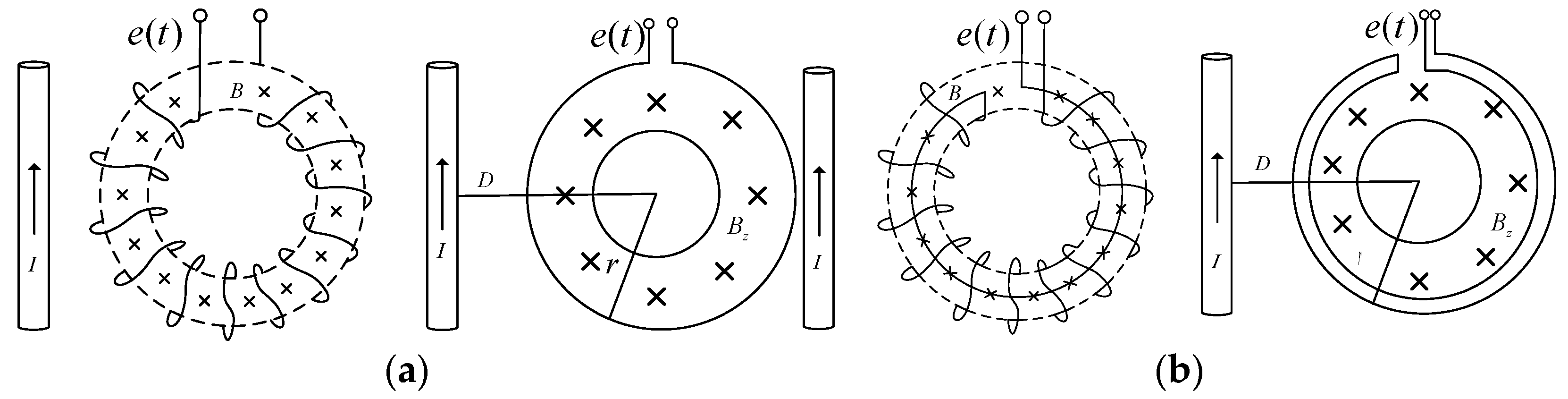
2.3. Interference Analysis of External Three-Dimensional Magnetic Field on Rogowski Coil

Rogowski coil in the actual measurement environment, will be affected by external, three-dimensional magnetic field interference, thus affecting the measurement results. This effect usually comes from the adjacent current. According to the position of the interfering magnetic field relative to the coil plane, the external three-dimensional magnetic field interference is divided into parallel and vertical aspects for analysis.
When the magnetic field of the interfering current I is perpendicular to the coil plane, the vertical interfering magnetic field B z is parallel to the cross section where the Rogowski coil is located, so no induced electromotive force is generated in the winding. However, the coil windings are connected in a series, creating an equivalent large circle after the coil has been wound once around, as shown in Figure 3a. As B z varies with time, an induced electromotive force e ( t ) will be generated in the Rogowski coil. A loop of equal area to the original winding needs to be designed to produce an equivalent reverse induction electromotive force to counteract this interference, as shown in Figure 3b, so that the induced electromotive force e ( t ) in the Rogowski coil is equal to zero.
When the interference magnetic field is parallel to the coil plane, the interference magnetic field produces two opposite induced voltages on the left and right sides of the coil. According to the external magnetic line and the spatial geometric position of the Rogowski coil, the structure diagram is drawn. The left side of the coil is shown in Figure 4a, and the right side of the coil is shown in Figure 4b.
Where I is the measured current, I is interference current, r the distance from the measured current to the coil reference point A , r the distance from the measured current to the coil reference point A , R is the distance from the interference current to the coil reference point A , R is the distance from the interference current to the coil reference point A , D is the distance between the interference current and the measured current; B is the magnetic induction intensity generated by the interference current at the reference point A , B is the magnetic induction intensity generated by the interference current at the reference point A , B x is the radial component of magnetic induction intensity at point A , B x is the radial component of magnetic induction intensity at point A , which is parallel to the coil winding and does not produce interference induced electromotive force, B y is the tangential component of the magnetic induction intensity B at point A , B y is the tangential component of the magnetic induction intensity B at point A , this part is perpendicular to the coil winding, will produce interference induced electromotive force; θ 1 is the angle between R and D at reference point I ; θ 1 is the angle between R and D reference point I , θ 2 is the angle between r and D at the reference point I ; θ 2 is the angle between r and D reference point I ; α is the angle between the parallel interference magnetic field B and the coil tangent at the reference point A , α is the angle between the parallel interference magnetic field B and the coil tangent at the reference point A .
According to the relevant analysis in reference [30], when the number of turns of the coil is n, the cross-sectional area of the coil is s, the coil is uniformly wound, and the winding shape of the symmetrical position is the same, the induced electromotive force on the left side of the coil is:
e 1 ( t ) = n s [ μ 0 π r arctan ( D + r D r ) μ 0 4 r ] d I d t
The induced electromotive force on the right side of the coil is:
e 2 ( t ) = - n s [ μ 0 π r arctan ( D + r D r ) μ 0 4 r ] d I d t
The total interference induced electromotive force produced by the parallel interference magnetic field on the whole coil is:
e ( t ) = e 1 ( t ) + e 2 ( t ) = 0
In order to eliminate the interference caused by the external parallel interference magnetic field, it is necessary to ensure that the coil winding is evenly distributed when the coil is closed, the cross-sectional area is uniform, and the plane of the single-turn coil should pass through the central axis of the Rogowski coil.

3. Open-ended PCB Rogowski Coil Structure Design

3.1. Determination of Rogowski coil Skeleton Parameters

The Rogowski coil skeleton is related to the stability of coil operation. In this paper, FR-4, which combines the advantages of good strength of glass fiber and good toughness of epoxy resin, is selected as the skeleton material of Rogowski coil.
Usually the thickness of the PCB board is 1.6 mm, and with increased thickness, processing costs will continue to improve. Thicker substrate will cause CNC or laser drilling difficulties, such as hole offset., With hole copper plating, it is difficult to ensure long-term reliability, so the thickness of the substrate is 1.6 mm.
For the determination of winding inner diameter and external b/a value of the coil. under the constraints of both measurement accuracy and production process, the most reasonable category of the ratio of b/a is between 1.6 and 2.4. This article sets the b/a value at 2.2.

3.2. Design of Rogowski Coil Winding Method

According to the characteristics of PCB processing technology, PCB processing can ensure the uniformity and consistency of Rogowski coil winding. As for the open-ended structure, the main consideration is whether the winding can be continuously and evenly distributed at the opening. As shown in Figure 5, the symmetrical wiring method is used to make the two half-rings of the opening completely symmetrical, and the distance between the left and right turns of the winding at the opening is consistent with that of other windings, i.e., d 1 = d 2 . when the two half-rings are completely closed, the winding of the whole coil is evenly distributed, which enhances the ability to resist the interference of external magnetic field changes in the parallel direction. On the double-layer PCB board, two rows of holes in the inner ring and one row of holes in the outer ring are placed in each half of the coils. The small circle is the through hole, the red line is the interactive route at the top, and the blue line is the interactive route at the bottom. The path of clockwise winding is the same as that of counterclockwise winding, but the direction is opposite. They contain the same planar region, increasing the ability to resist the interference of externally varying magnetic fields in the vertical direction. A layer of copper wire is placed on the outermost ring of the winding to resist the influence of the external electric field on the coil.
In Figure 5, on the semi-ring PCB are set three rows of holes from inside to outside, labeled A, B, C. In addition, a transition hole D is added to each semiring, and a wiring in obtuse angle form is used at the vias for transition. The number of the hole starts counterclockwise sorting from A1, B1, C1. The PCB coil with 20 turns in the upper half loop is taken as an example. The winding along the winding path is C1–A1–C3–A2–...–C19–A10. After passing through D, the winding begins to turn back, and the winding path is D-B10–C20–B9–C18–...–B1–C2. This winding method should keep the same direction of the wire winding skeleton when it is winding along and winding back, otherwise it will offset the measured induced electromotive force generated by the winding along and winding back. The winding wiring of the lower half-ring coil is the same as that of the upper half-ring coil, E1 and E2 are connected to make the induction voltage of the upper and lower half-ring superimposed. F1 and F2 are the output terminals of the Rogowski coil signal.

3.3. Design of Coil Winding Parameters

Considering the existing PCB processing technology, the number of turns of the PCB coil is limited by its inner diameter and through hole size. The distance between the two holes is at least three times the width of the pad, making PCB manufacturing convenient, the narrower the width of the wire, the greater the difficulty of processing. The winding parameters of the designed coil are shown in Table 1:
There are two types of windings in the coil design: AC and BC, whose total mutual inductance is the sum of the mutual inductances of the different types of turns. As with the total mutual inductance, the same is true for the self-inductance of the Rogowski coil. The two parameters are calculated as follows.
M = N × μ × h 2 × π × ( ln b R A + ln b R B )
L 0 = N 2 × μ × h 2 × π × ( ln b R A + ln b R B )
Internal resistance of the coil:
R 0 = ρ × l A
where ρ = 1.68 × 10 8   Ω / m is resistivity of copper.
The lumped stray capacitance of a PCB Rogowski, which mainly includes the capacitance between the wires on the same side of the double panel, the capacitance distributed between the wires on both sides, and the shielding capacitance, can be obtained by complex numerical analysis or measurement. In this paper, the total stray capacitance of the coil will be measured using experimental methods.

3.4. Measurement of Rogowski coil Parameters

According to the lumped parameter modeling analysis of Rogowski coil in Section 2.2, the equivalent impedance Z(s) in s-domain circuit is derived as follows:
Z ( s ) = L o s + R o L o C o s 2 + R o C o s + 1
The electrical parameters of Rogowski coil were measured by LCR3535 impedance meter of HOKA company. Figure 6a is the physical diagram of the open-ended PCB Rogowski coil, and Figure 6b is the schematic diagram of the coil electrical parameters measurement experiment. The inductance of the coil is 9 μH, and the resistance is 25.6 Ω. The lumped stray capacitance in the coil cannot be directly measured. Usually, the first resonant frequency of the amplitude-frequency response of the impedance is used for theoretical deductions. The formula is as follows:
C 0 = 1 L 0 ω 0 2 R d + R 0 R d
The impedance of the Rogowski coil is measured by sweep frequency, and the measurement results are shown in Figure 7a. From the measured impedance sweep curve, it is known that the first resonance point of the coil’s impedance is at 14.68 MHz. According to Equation (18), the total set stray capacitance is 12 pF. According to Equation (17), the theoretical sweep frequency curve is obtained and compared with the measured impedance sweep frequency curve. The results are shown in Figure 7b.
It is known that the theoretical impedance agrees well with the measured impedance. In summary, the basic parameters of the coil set total parameter model are determined as shown in Table 2 below:

4. Design of Integrator

The output of Rogowski coil is a is a signal proportional to the current derivative. In order to recover the current to be measured, it must be used with an integrator. The working state of the Rogowski coil is divided into self-integrator and external integrator, as shown in Figure 8. Among them, the self-integrator is suitable for measuring high frequency and large current, the measurement bandwidth is limited, the sensing gain is small and the output signal is weak. The external integration can measure the low frequency components with relatively high sensitivity. In this paper, we need to cover the measurement from low frequency to high frequency, so we use external integration.
External integrator has source integrator and active integrator. The simplest passive integrator is only composed of a resistor R and a capacitor C. The passive integrator must use the integrator with large RC time constant to ensure that the low frequency component of the signal is not distorted, and the high frequency response ability of the integrator will deteriorate. Different from the passive integrator, the active integrator is not easily affected by the load at its output end, and its range can be extended to the low-frequency part. However, since the active integrator will increase its low-frequency gain, amplify the low-frequency noise and affect the measurement results, the range of active integrator should not be excessively expanded. Reference [18] proposed a hybrid integrator, as shown in Figure 9:
The integrator scheme consists of a passive RC integrator network and an active integrator network. In the active integrator part, the in-phase integrator circuit is selected to overcome the shortcomings of the traditional inverse integrator. The passive integrator integrates the high frequency, and the active integrator integrates the low frequency. In this way, the amplifier can maintain its wide bandwidth. Due to the large number of turns of the coil and the winding height of several meters, the impedance matching of the measurement system must be considered when using this circuit in conjunction with the PCB Rogowski coil. Considering that the characteristic impedance of the Rogowski coil is different from that of the hybrid integral circuit, it is necessary to connect the Rogowski coil and the hybrid integral circuit with a 50 Ω coaxial cable. A 50 Ω resistor is connected between the coaxial cable and the passive integral circuit by using the principle of back-end matching. At the same time, a capacitor is replaced by two capacitors in parallel to reduce the series inductance of the capacitor and the refraction and reflection of the high frequency measurement. The improved integral circuit, as shown in Figure 10:
In the integrator circuit, the measured signal passes through a passive integration to realize the integration of high frequency signal, and then through a high-pass filter to eliminate the low frequency interference of amplifier output. Finally, it passes through an active integrator to realize the integration of the low frequency part. The transfer function of the hybrid integrator is as follows:
H ( s ) = ( 1 R 1 ( C 1 + C 3 ) + 1 ) ( R 3 R 2 × R 2 C 2 S + 1 R 3 C 2 S + 1 ) ( R h C h S R h C h + 1 )
In order to achieve a constant sensitivity of the sensor in the operating frequency range, it is necessary to match the passive and active integrator time constants. In order to achieve a smooth integration transition between passive and active integration, it is necessary to make R 1 ( C 1 + C 3 ) = R 2 C 2 Combined with the parameters of the open-ended Rogowski coil in Section 3.3, the specific parameters of the hybrid integrator are shown in Table 3.
The simulation software is used to draw the frequency characteristics of the integrator, and the characteristics of the active in-phase integrator are shown in Figure 11a, which obviously proves that the signal with frequency range f1 < f < f2 can be integrated, where:
f 1 = 1 2 π R 3 C 2 = 33.86   Hz
f 2 = 1 2 π R 2 C 2 = 23.41   kHz
The frequency characteristics of the passive integrator are shown in in Figure 11b, and its integration range is f > f 2 . The total frequency characteristic curve of the hybrid integrator obtained after compounding the two is shown in Figure 11c, which can achieve the integration above 33.86 Hz. The frequency response curve shown in Figure 11d is obtained by using the signal generator to sweep the frequency of the hybrid integrator. The results show that the hybrid integrator designed in this paper can meet the integration requirement of up to 10 MHz.
In addition, the selection of load resistance is also crucial for the whole measurement system, and its reasonable selection can better broaden the high frequency cutoff frequency of the measurement system. According to the optimal damping coefficient, the second order system is 0.707 and, in Equation (10), the load resistance of Rogowski coil is 610 Ω. Figure 12 simulates the amplitude-frequency response curves of several sensors with different load resistance. From the graph, the system response is better when the load resistance is 610 Ω.

5. Experiment Results

5.1. Effect of Opening on PCB Rogowski Coil

In order to verify the performance of the open-ended PCB Rogowski coil probe, the experimental platform in Figure 13a was built using a signal generator, a power amplifier, a non-inductive resistor, a host computer and an oscilloscope. The upper computer is programmed by LabVIEW. It controls the signal generator and oscilloscope, changes the frequency of the sine of the signal generator, outputs a voltage of constant amplitude and varying frequency, and controls the oscilloscope to collect the output voltage signals of the HIOKI CM-100-M, and both the closed and open-ended PCB Rogowski coil. (The parameters such as Wiring method, number of turns and size of the closed PCB Rogowski coil are the same as those of the open-ended Rogowski coil). The three signals are processed to obtain the measured amplitude-frequency response curves of the open and closed-ended Rogowski coils. As can be seen from Figure 13b, when the measurement conditions are the same, the output amplitude-frequency characteristic curves of the closed and open-ended PCB Rogowski coils are basically the same, and the difference between the mutual inductance values is less than 0.5%.

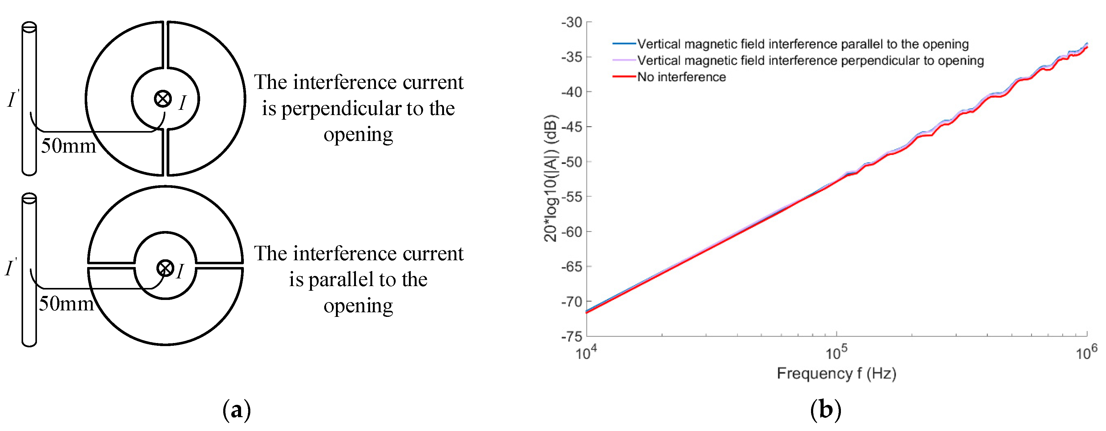
5.2. Interference Test of External Three-Dimensional Magnetic Field on Open-Ended Rogowski Coil

In order to verify the influence of external three-dimensional interference magnetic fields on the output characteristics of open-ended Rogowski coil, it is necessary to test the output frequency characteristics of the coil when there are parallel external magnetic field interference and vertical external magnetic field interference.
The experimental platform for generating the interference current and the measured current is set up as shown in Figure 14a. The current generated by the power amplifier is separated into two identical current signals through two inductanceless resistors with the same resistance value in the two branches of a and b, where branche a is the interference signal and branche b is the measured signal. Figure 14b is the experimental scene. The interfering current and the measured current are placed in the same plane and parallel to each other, the distance between the two centers is 50 mm, and the current magnitude is equal to 1A. The interfering current-carrying conductor is positioned parallel or perpendicular to the coil opening, as shown in Figure 15a. The results of the coil amplitude-frequency response curves of the two placement methods are shown in Figure 15b. It can be seen that when the coil interference current is perpendicular to the coil opening, the magnetic field interference parallel to the PCB plane has a very small effect on the output characteristics of the coil, only 0.73%, which is due to this placement method. The wiring of the left and right half-loops of the coil is basically the same. This makes the parallel interference current in the left and right loops of the coil, generated by the induction potential, of equal size and opposite polarity, thus canceling each other. When the coil interference current is parallel to the coil opening, the effect of the magnetic field interference parallel to the PCB plane on the coil output characteristics is also relatively small, only 1.45%. This is because the coil closure is not guaranteed to be absent of any air gap at all.
When testing the influence of vertical interference on the output characteristics of the open-ended PCB coil, the placement modes of interference current, coil and measured current are shown in Figure 16a, where the interference current is parallel or perpendicular to the position of the coil opening, the current is 1A, and the distance from the measured current is 50 mm. The measurement results of the coil are shown in Figure 16b. It can be seen that whether the position of the interference current carrier and the coil opening is parallel or vertical, the influence of the vertical interference magnetic field on the amplitude-frequency response characteristics of the coil output is very small, only 0.56%.

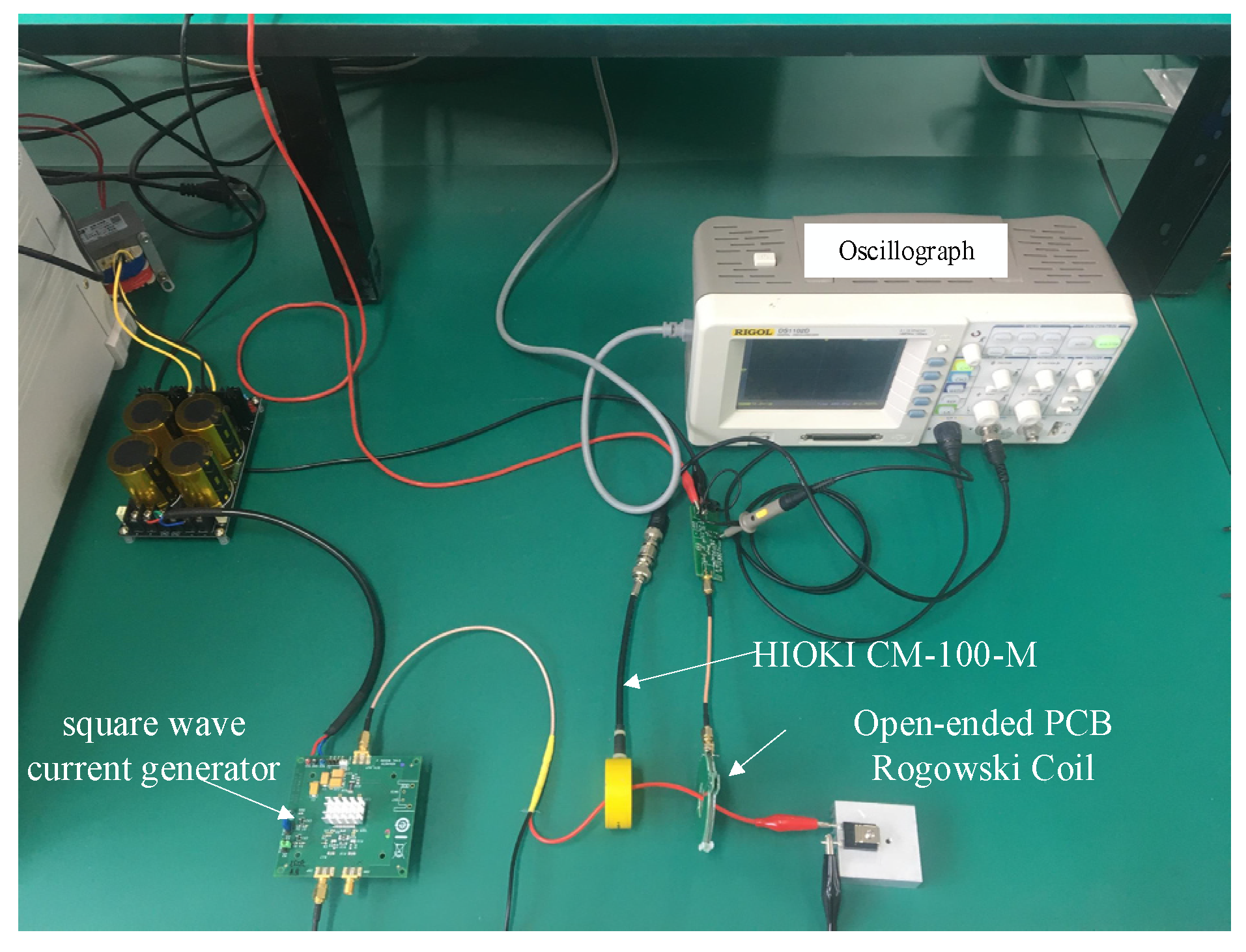
5.3. Sensor Overall Performance Testing

In order to verify the influence of different integral configurations on the overall performance of open Rogowski coil current sensor, using the platform built in Figure 13a, the open Rogowski coil is connected with three different integral configurations, such as no coaxial cable, coaxial cable, coaxial cable and back-end matching. The amplitude-frequency characteristics of the sensor under three configurations are compared. Repeat the above experiments, the amplitude-frequency response curve of the sensor shown in Figure 17 is obtained. It can be seen that in the frequency range of 34 Hz–20 kHz, the amplitude-frequency characteristic curves of the sensor in the three integration configurations remain the same. In the frequency range of 20 kHz–1 MHz, a very obvious resonance appears under the condition that the coil is not connected to the integrator with coaxial cable, and after adding the coaxial cable, the resonance appears to be better, and after adding the coaxial cable and adding the back-end matching, the resonance appears to be significantly better. The experimental results show that the high frequency measurement can be significantly improved by connecting the Rogowski coil to the integrator with the coaxial cable and adding the back-end matching circuit.
It is very difficult to realize a frequency response measurement up to MHz with a current amplitude in the measurement range of the current sensor. Therefore, different measurement methods need to be used to verify the wide bandwidth of the current sensor. In Figure 17, the purple line depicts the measurement frequency response curve of an open-ended PCB coil sensor with a measurement frequency up to 1 MHz. The input current to be measured has a constant amplitude and the output is normalized to the input value to achieve a response amplitude of about −44 dB in the measurement range.
In addition, rectangular current waveform contains more harmonic components than other waveforms (such as triangular waveform), so it is very effective for current sensors [31]. This paper uses the rectangular current method to measure the high-frequency response. The rectangular current pulse is generated by a voltage pulse source (its rise time is up to 100 ns) and an external inductanceless resistor. A longer duration is selected to display the low frequency performance of the current sensor. The input signal and the output signal of the open Rogowski coil are recorded simultaneously by a signal cable with a characteristic impedance of 50Ω, which matches the output impedance of the pulse source of 50Ω and the input impedance of the measuring instrument of 50 Ω. The experimental scene is shown in Figure 18.
In order to better observe, the pulse current signals measured by Reference HIOKI CM-100-M and open-ended PCB Rogowski coil are normalized to obtain the response diagram of the sensor pulse signal, as shown in Figure 19. It is known that the response process of the reference current sensor matches well with the response process of the Rogowski coil current sensor. The measurement signal of the open-ended PCB Rogowski coil current sensor shows high signal fidelity, but oscillates around the measurement signal of the reference sensor. These oscillations are caused by the capacitive coupling of the Rogowski coil to the pulsed power supply and are mainly concentrated during the rising and falling edges of the current pulse. The rise times of the reference current probe and the open-ended sensor were measured to be 100 ns and 102 ns, and the high-frequency cutoff frequency of the measurement system was calculated to be >3.5 MHz based on the relationship between the rise time T r and the highest frequency measured B W [32]. The calculation formula is as follows:
B W = 0.35 T r

6. Conclusions

In this paper, an open-ended type, wide frequency PCB Rogowski coil based on a new winding method is designed. By improving the method of loop winding, the holes of the Rogowski coil are less and it is easy to batch production. It also adopts obtuse angle wiring at the over-hole as well as other places, and a uniform wiring method at the mouth opening, which effectively increases the anti-interference ability of the coil when measuring current. The high-frequency measurement performance of the sensor is improved by using a compound integration circuit and back-end matching. Through the test, the mutual inductance difference between the closed-ended coil and the open-ended coil is less than 0.5% under the same wiring method of the PCB coil. Under the interference of the equivalent current 50 mm away from the measured current, the influence of the interference current-carrying conductor parallel to the measured wire on the mutual inductance of the coil is 0.59%. This is in comparison to the measurement results—(0.69%) of the closed PCB Rogowski coil under the equivalent current interference, at 43 mm from the measured current proposed in Reference [9]. They are basically consistent. Additionally, in this paper, when the interfering current-carrying conductor is on the same side as the coil and 50 mm away from the center, the effect of the interfering current-carrying conductor, parallel to the wire under test on the mutual inductance of the coil, is measured to be 1.45%, which is also very small. The sensitivity is 6.3 mV/A in the frequency range of 34 Hz–1 MHz when the open-ended PCB Rogowski coil is used with the hybrid integrator. Under the impulse square wave, the time-domain response waveform and the input waveform follow well, and the measured rise time is 102 ns, which can realize the current measurement of up to 3.5 MHz.

Author Contributions

The idea of this work was proposed by W.Z. and Q.T.; Y.H., X.T., L.Y., Y.R. and Q.T. performed the experiments and analyzed the results. Q.T. wrote the paper. All authors have read and agreed to the published version of the manuscript.

Funding

“Research and development of new smart sensor technology to promote the development of green energy” (202104BN050011) funding.

Conflicts of Interest

The authors declare no conflict of interest.

References

  1. Costa, F.; Poulichet, P.; Mazaleyrat, F. The current sensors in power electronics, a review. EPE J. 2001, 11, 7–18. [Google Scholar] [CrossRef]
  2. Su, B.; Li, L.X.; Zheng, Y.H.; Wang, X.; Liu, Y.; Dang, C.L. Design and Analysis of PCB Rogowski Coil Current Transformer. Appl. Mech. Mater. 2014, 672–674, 984–988. [Google Scholar]
  3. Kojovic, L. PCB Rogowski coils benefit relay protection. IEEE Comput. Appl. Power 2002, 15, 50–53. [Google Scholar] [CrossRef]
  4. Gang, Z.; Yi, L. Positional Error Analysis of PCB Rogowski Coil for High Accuracy Current Measurement. Adv. Mech. Eng. 2013, 2013, 323–335. [Google Scholar]
  5. Di, Z.G.; Jia, C.R.; Zhang, J.X. PCB rogowskicoil for electronic current transducer. Sens. Transducers 2014, 171, 206–213. [Google Scholar]
  6. Li, W.; Mao, C.; Yu, Y. Study of property of Rogowski coil applied for measuring the switching current of RSD device. Trans. China Electrotech. Soc. 2006, 21, 49–53. [Google Scholar]
  7. Ostmann, A. Embedded power electronics for automotive applications. In Proceedings of the 7th International Microsystems, Packaging, Assembly and Circuits Technology Conference (IMPACT), Taipei, Taiwan, 24–26 October 2012. [Google Scholar]
  8. Liu, Y.; Xie, X.; Hu, Y. A novel transient fault current sensor based on the PCB Rogowski coil for overhead transmission lines. Sensors 2016, 16, 742. [Google Scholar] [CrossRef] [PubMed]
  9. Tao, T.; Zhao, Z.; Ma, W. Design of PCB Rogowski coil and analysis of anti-interference property. IEEE Trans. Electromagn. Compat. 2016, 58, 344–355. [Google Scholar] [CrossRef]
  10. Koh, J.S.; Venkatarayalu, N. Modeling, analysis and measurement of characteristics of printed coils for current monitoring applications. In Proceedings of the IEEE Region 10 Conference (TENCON), Singapore, 22–25 November 2016; pp. 3119–3122. [Google Scholar]
  11. Fritz, J.N.; Neeb, C.; Doncker, R.D. A PCB Integrated Differential Rogowski Coil for Non-Intrusive Current Measurement Featuring High Bandwidth and dv/dt Immunity; Power and Energy Student Summit(PESS) 2015; Department of Health: Dortmund, Germany, 2015; pp. 1–6.
  12. Wang, J.; Chen, W.; Chen, P. A Design Method of PCB Rogowski Coil in Limited Space and Modified Integral Circuit. IEEE Sens. J. 2020, 20, 5801–5808. [Google Scholar] [CrossRef]
  13. Montrose, M.I. Right angle corners on printed circuit board traces, time and frequency domain analysis. In Proceedings of the IEEE International Symposium on Electromagnetic Compatibility (IEEE Cat. No. 99EX147), Tokyo, Japan, 17–21 May 1999; pp. 638–641. [Google Scholar]
  14. Wei, B.; Fu, Z.; Wang, Y.J. Frequency response analysis of passive RC integrator. High Volt. Eng. 2008, 34, 53–56. [Google Scholar]
  15. Samimi, M.H.; Mahar, A.; Farahnakian, M.A.; Mohseni, H. The Rogowski coil principles and applications: A review. IEEE Sens. J. 2014, 15, 651–658. [Google Scholar] [CrossRef]
  16. Shafiq, M.; Kutt, L.; Lehtonen, M.; Nieminen. Parameters identification and modeling of high-frequency current transducer for partial discharge measurements. IEEE Sens. J. 2012, 13, 1081–1091. [Google Scholar] [CrossRef]
  17. Ray, W.F.; Hewson, C.R. High performance Rogowski current transducers. In Proceedings of the Conference Record of the 2000 IEEE Industry Applications Conference, Thirty-Fifth IAS Annual Meeting and World Conference on Industrial Applications of Electrical Energy (Cat. No. 00CH37129), Rome, Italy, 8–12 October 2000; Volume 5, pp. 3083–3090. [Google Scholar]
  18. Wang, B.; Wang, D.; Wu, W. A Rogowski coil current transducer designed for wide bandwidth current pulse measurement. In Proceedings of the IEEE 6th International Power Electronics and Motion Control Conference, Wuhan, China, 17–20 May 2009; pp. 1246–1249. [Google Scholar]
  19. Metwally, I.A. Design of different self-integrating and differentiating Rogowski coils for measuring large-magnitude fast impulse currents. IEEE Trans. Instrum. Meas. 2013, 62, 2303–2313. [Google Scholar] [CrossRef]
  20. Rogowski, W.; Steinhaus, W. Die Messung der magnetischen Spannung. Arch. Für Elektrotechnik 1912, 1, 141–150. [Google Scholar] [CrossRef] [Green Version]
  21. Hlavacek, J.; Prochazka, R.; Knenicky, M.; Draxler, K.; Styblikova, R. Influence of Rogowski coil shielding to measurement results. In Proceedings of the 17th International Scientific Conference on Electric Power Engineering (EPE), Prague, Czech Republic, 16–18 May 2016; pp. 1–5. [Google Scholar]
  22. Hu, C.; Li, H.; Jiao, Y.; Zhang, Z.; Li, K. Comparative analysis of various models of Rogowski coil for very fast transient study. IEEJ Trans. Electr. Electron. Eng. 2018, 13, 1319–1327. [Google Scholar] [CrossRef]
  23. Nassisi, V.; Serra, A. Influence of Rogowski coil structure for sub-ns current pulses. Rev. Sci. Instrum. 2021, 92, 073303. [Google Scholar] [CrossRef]
  24. Nassisi, V.; Luches, A. Rogowski coils: Theory and experimental results. Rev. Sci. Instrum. 1979, 50, 900–902. [Google Scholar] [CrossRef]
  25. Xiang, M.J. Research on Traveling Wave Transmission Characteristics and Application Technology Based on Rogowski Coil; Shandong University: Shandong, China, 2013. [Google Scholar]
  26. Hashmi, G.M.; Lehtonen, M.; Elhaffar, A. Modeling of rogowski coil for on-line pd monitoring in coveredconductor overhead distribution networks. In Proceedings of the CIRED 19th international conference on electricity distribution, Vienna, Austria, 21–24 May 2007. [Google Scholar]
  27. Hashmi, G.M.; Lehtonen, M.; Nordman, M. Calibration of on-line partial discharge measuring system using Rogowski coil in covered-conductor overhead distribution networks. IET Sci. Meas. Technol. 2011, 5, 5–13. [Google Scholar] [CrossRef]
  28. Jiao, C.; Zhang, J.; Zhao, Z.; Zhang, Z.; Fan, Y. Research on small square pcb rogowski coil measuring transient current in the power electronics devices. Sensors 2019, 19, 4176. [Google Scholar] [CrossRef] [Green Version]
  29. Ahmed, A.; Coulbeck, L.; Castellazzi, A.; Johnson, C.M. Design and test of a PCB Rogowski coil for very high dI/dt detection. In Proceedings of the 2012 15th International Power Electronics and Motion Control Conference (EPE/PEMC), Novi Sad, Serbia, 4–6 September 2012; pp. DS1a.2-1–DS1a.2-4. [Google Scholar]
  30. Habrych, M.; Wisniewski, G.; Miedziński, B. HDI PCB Rogowski coils for automated electrical power system applications. IEEE Trans. Power Deliv. 2017, 33, 1536–1544. [Google Scholar] [CrossRef]
  31. Tröster, N.; Wölfle, J.; Ruthardt, J. High bandwidth current sensor with a low insertion inductance based on the HOKA principle. In Proceedings of the 2017 19th European Conference on Power Electronics and Applications (EPE’17 ECCE Europe), Warsaw, Poland, 11–14 September 2017; pp. 1–9. [Google Scholar]
  32. Zhang, D.L. Development of Differential-Integral Pulse High-Voltage Divider; Southeast University: Nanjing, China, 2017. [Google Scholar]
Figure 1. Principle of a Rogowski Coil. (a) Structure Diagram of traditional Rogowski coil; (b) Structure Diagram of PCB Rogowski coil.
Electronics 11 00381 g001
Figure 2. The lumped parameter model of Rogowski coil.
Electronics 11 00381 g002
Figure 3. Diagram of interference of external vertical magnetic field on coil. (a) Equivalent large turn without return line; (b) Rogowski coil with the return line.
Electronics 11 00381 g003
Figure 4. The impact of horizontal magnetic field (a) Interference to left coil; (b) Interference to right coil.
Electronics 11 00381 g004
Figure 5. Schematic diagram of winding mode of open-ended PCB Rogowski coil.
Electronics 11 00381 g005
Figure 6. Coil electrical parameter measurement. (a) Physical diagram of open-ended PCB Rogowski coil; (b) Experimental diagram of coil electrical parameter measurement.
Electronics 11 00381 g006
Figure 7. Impedance Sweep Curve. (a) Measured Impedance Sweep Curve; (b) Theoretical Correction and Measured Anti-Sweep Curve.
Electronics 11 00381 g007
Figure 8. Self-integrator and external integrator.
Electronics 11 00381 g008
Figure 9. Hybrid Integration.
Electronics 11 00381 g009
Figure 10. Improved integral circuit.
Electronics 11 00381 g010
Figure 11. Amplitude-frequency curve. (a) Simulation amplitude-frequency curve of the RC integrator; (b) Simulation amplitude-frequency curve of the passive integrator; (c) Simulation amplitude-frequency curve of the hybrid integrator; (d) Measure amplitude-frequency curve of the hybrid integrator.
Electronics 11 00381 g011
Figure 12. Amplitude-frequency response curve of the sensor under different load resistors.
Electronics 11 00381 g012
Figure 13. Effect of Opening on PCB Rogowski Coil. (a) Rogowski coil probe test platform; (b) Measured amplitude-frequency response curve of Rogowski coil.
Electronics 11 00381 g013
Figure 14. Test platform for external magnetic field interference of open-ended Rogowski coil. (a) Schematic diagram; (b) Field diagram.
Electronics 11 00381 g014
Figure 15. Horizontal magnetic field interference. (a) Placement method; (b)The amplitude-frequency response curve of Rogowski coil with external parallel interference.
Electronics 11 00381 g015
Figure 16. Vertical magnetic field interference. (a) Placement method; (b)The amplitude-frequency response curve of Rogowski coil in the presence of external vertical interference.
Electronics 11 00381 g016
Figure 17. Amplitude-frequency characteristic curves of the sensors with different integration states.
Electronics 11 00381 g017
Figure 18. Field diagram of square wave test platform.
Electronics 11 00381 g018
Figure 19. Response diagram of sensor pulse signal.
Electronics 11 00381 g019
Table 1. Winding parameters of coils.
ParametersValues
Width of winding wire ω 0.1 mm
Thickness of winding wire h 0.035 mm
Number of winding turns N 180
Inner diameter of winding R A 11 mm
Inner diameter of winding R B 12 mm
Outer diameter of winding b 24.5 mm
Winding length l 5.21 m
Cross-sectional area of winding A 3.5 × 10 9   m 2
Table 2. Lumped parameter of coil.
ParametersValues
self-inductance M 46.12 nH
lumped resistance R 0 25.6 Ω
lumped inductance L 0 9 μH
lumped stray capacitance C 0 12 pF
Table 3. Lumped parameter of coil.
ParametersValues
R 1 6.8 kΩ
C 1 0.5 nF
C 3 0.5 nF
R 2 6.8 kΩ
C 2 1 nF
R 3 4.7 MΩ
R h 6.8 kΩ
C h 1 uF
Publisher’s Note: MDPI stays neutral with regard to jurisdictional claims in published maps and institutional affiliations.

