1. Introduction
Proximity sensors have been employed across numerous existing and emerging fields such as robotic technologies, bio-electronic devices, parking sensors and human–machine interfaces [
1], with an emphasis on a broad usage within industries like transportation, manufacturing as well as building automation and Industrial Internet of Things (IIoT) [
2]. Since it is expected that the utilization of proximity sensors will increase even more, their power consumption has become a crucial attribute of such devices calling for more in-depth research and development of more energy-efficient sensors [
3]. What is more, cost-effective and reliable proximity sensors that are satisfactory accurate are especially important for use case scenarios such as angle measurements used in robots that include wheel positioning and joint angle measurement [
4], for collision avoidance, precision assembly as well as grasping [
5].
This paper addresses utilization of an in-house developed contactless omnidirectional capacitive sensor as a promising solution for human–machine interface applications. An extensive experiment has been conducted to compare the performance of the capacitive with other sensors commonly used in similar applications: ultrasonic, infrared and time-of-flight sensor. The omnidirectional sensor proposed in this manuscript has a potential to overcome the shortcomings of the above mentioned sensors in terms of directivity. To be specific, the time-of-flight (TOF) sensors mostly exhibit high linearity and wide sensing range, yet very narrow sensing angle (effectively a dot). Most of the ultrasonic and optical proximity sensors are also highly directional [
6,
7,
8]. On the other hand, a capacitive sensor presents an exception to this limitation by inherently being non-directional. In addition, the sensing element of a capacitive sensor can be of arbitrary shape and dimensions, hence being adaptable to a variety of device enclosures. Furthermore, an almost instantaneous response allows to duty-cycle the power supply whilst providing correct output value, reducing the overall power consumption. Cost-wise, the presented sensor is plain and simple in design, using several CMOS logic gates and a digital potentiometer which is used for self-adjustment purposes. A major drawback of most currenty used capacitive sensors is a short sensing range (generally below 1 cm [
9]), restricting their usage to capacitive keypads and touch screens, both of which merely detect a direct contact with human finger. Based on experimental findings, the device presented in this paper can be employed for proximity sensing applications within the 5–10 cm range.
2. Technological Background
To this date, a variety of different sensor technologies have been developed for sensing distance or proximity of an object. With that regard, proximity sensors have been produced and brought to the market in form of infrared, ultrasonic, magnetic induction as well as capacitive sensors [
1]. Choice of a particular sensor depends on the application, resilience to harsh environment conditions, low cost, high energy efficiency and long life cycle [
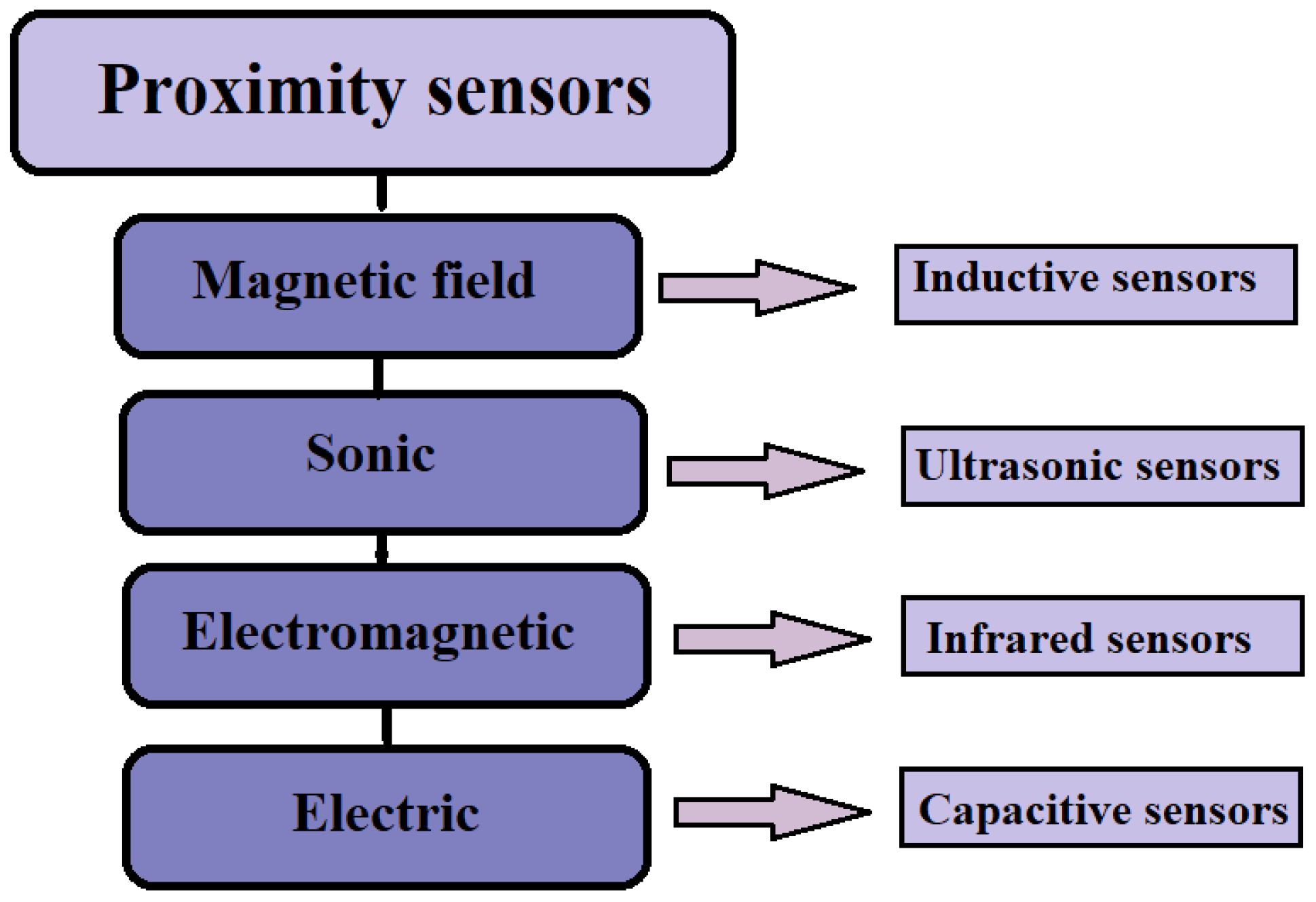
10]. Generally, a proximity sensor will provide a non-contact detection of objects within its range and distinguished based on physical phenomenon utilized for sensing [
2], as depicted in
Figure 1. For instance, inductive sensors employ electromagnetic induction to detect objects by sensing the change of inductance of a coil, since a nearby object will disturb the generated magnetic field [
11]. Although the objects do not need to be ferromagnetic, the ones that are highly conductive, like metal ones, will strongly affect an alternating magnetic field [
12]. Due to their robustness to harsh environmental conditions, durability, safety and non-mechanical contact, inductive proximity sensors have broadly been utilized in many areas such as aviation field [
13], or in IoT applications like parking place availability sensors [
14] as well as in a form of angle sensors in the automotive applications [
4]. Furthermore, a study given in [
15] presents an ultra-low power proximity sensor using electrostatic induction for detection of human motion.
Sonic sensors such as ultrasonic sensors have also been applied as proximity sensors [
2,
16,
17]. Basis of operation for ultrasonic sensors is founded on the Time-of-Flight (ToF) principle measuring the time needed for the acoustic wave to travel from the transmitter to the object and bounce back to the receiver [
6] and are deemed to be quite precise for measuring tiny distances. Generally, two types of ultrasonic sensors can be distinguished: Ultrasonic Proximity Detection and Ranging Measurement; the first ones will sense an object passing within it’s range and output a signal, where the second one will precisely measure the distance from the object by determining the time intervals among the sent and received bursts of ultrasonic waves [
18]. Utilization of ultrasonic sensors ranges from process industry [
19], robotics [
6], within IoT for employment such as water level detection [
20] and with a very significant applications within automobile industry [
18]. For instance, these sensors are applied within self-driving vehicles [
21], as well as in IoT concept of Smart Parking solutions as occupancy detection sensors [
22]. Ultrasonic proximity sensor has also been applied for safe operation of human friendly robots [
23], as well as for robot safety control as presented in [
6]. One of the main reason for their frequent usage is their low cost and simple installation, energy efficiency, low maintenance combined with high sensitivity and frequency, as well as uncomplicated interface with a micro-controller or any type of controller [
18]. One of their main disadvantages is that they are prone to environmental changes.
Infrared (IR) sensors are being broadly utilized as proximity sensors in robotics for detection of nearby objects and obstacle avoidance, operating typically based on triangulation [
8]. In general, IR sensors emit and detect infrared radiation to sense their surrounding environment [
21], where the distance to the sensed object depends on the angle at which the reflected light returns to the sensor [
24]. When considering proximity sensing, IR sensors abide by photometry inverse square law where the illuminance intensity is inversely proportional to the square of the distance between the light source and the illuminated object. The illuminance will increase linearly with the intensity of the emitting infrared diode and decrease with the cosine of the angle of incidence [
25]. In comparison to ultrasonic sensors infrared sensors are more cost-effective having a swifter response, but since they are more sensitive to noisy environment, measurement precision for proximity purposes may be affected [
7]. Presently, IR sensors are being utilized within numerous IoT applications ranging from healthcare, for instance in non-contact-based temperature measurements, smart home appliances, smartwatches as well as automotive blind-angle detection [
21]. Their expanded usage has led to development of new generation of IR sensors with enhanced cross-sensitivity achieved with integration of sensor and emitter with digital signal processing [
25]. Furthermore, research in [
26] describes a low-cost IR reflective proximity sensors which can be applied to measure displacements with sub-microlevel accuracy whose utilization is important in the context of emerging micro/nanotechnology. Infrared proximity sensors have also been frequently applied for detection of human presence in the building aiming to decrease energy consumption [
27]. One such IR sensor implementation has recently been considered in [
28] for smart home purposes. The use of IR sensors has also been examined in robotic applications such as in [
24], exploring the possibilities of obtaining rough 3D information about target objects or robots’ surroundings.
Finally, when considering the class of electric proximity sensors, capacitive proximity sensors (CPSs) have been most extensively applied. Their sensing occurs upon the perturbance of the sensors’ electric field caused by a nearby object, that shifts the sensor’s capacitance [
29]. Applications of CPSs can be found in various domains such as object identification in robotics, proximity perception in human-centered robotics up to continuous touch gesture recognition [
2,
12,
30]. Due to their design flexibility and simplicity, cost-effectiveness and low power consumption, CPSs are widely used in comparison to other proximity sensors [
31]. Capacitive proximity sensors can be easily calibrated with adequate response performance and are able to estimate distance from several millimeters up to several centimeters from metallic as well as nonmetallic objects [
32]. The distance from the object is measured based on the capacitance created among the CPSs surface and the object surface where CPSs can be classified based on the measurement principle as self-capacitance [
33] and mutual-capacitance sensors [
34]. In the case of self-capacitance CPSs the object is required to be a grounded conductor (therefore it is prone to the influence of its surrounding stray electric field) and capacitance established between the sensor and the object alters along with object’s distance from the sensor where the range of distance sensing is approximately only a few millimeters [
32]. In the mutual-capacitance scenario, the object and sensor are regarded as two plates stationed on the same plane, where mutual capacitance among these two plates is generated as the object moves [
34]. Mutual-capacitance sensors are able to measure the distance from conductive as well as non-conductive objects, but not the direction of the object movements [
32]. Although different proximity sensing technologies have been employed for particular purposes, capacitive proximity sensors prevail over others. In general, the capacitance between the sensor and an object is closely related to the object shape as well as its material and relative location from the sensor [
12]. Capacitive proximity sensors have been utilized within numerous fields like smart environment applications [
31,
34], in gesture recognition [
30], in human-centered robotics [
12]. Furthermore, CPSs have been extensively researched within the field of human–computer interaction, as presented in research [
29]. A role of CPSs working in displacement sensing modality has also been comprehensively examined within study given in [
31]. Furthermore, researchers in [
32] have designed a capacitve proximity sensor which can distinguish four different directions and measure the object distance in the range of 1–40 mm simultaneously.
3. Materials and Methods
The proposed sensor is based upon a heterodyning technique used in theremin [
35,
36]. There is a commercially available theremin shield for Arduino (OpenTheremin product page:
https://www.gaudi.ch/OpenTheremin/ accessed on 20 December 2021) which operates on similar principle as the one used in our proposed device, but with a greater complexity and at a higher price point. The simplicity of our device also leads to a lower power consumption. Our sensor consists of two digital oscillators, one of which (primary/sensing) is connected to a sensing (conductive) plate. Should a grounded object come within the sensing range, the total capacitance in the oscillator would increase, changing the frequency of the generated square wave.
The other (secondary/adjustment) oscillator is kept at a constant frequency which is being adjusted during the power-on phase, while there is no object present other than the static environment. The frequency adjustment must be performed remotely, without introducing additional capacitance in the circuit. The constant-frequency square wave is combined with the variable-frequency square wave using logical XOR operation. This approach is generally employed in digital phase detectors, but can be used to simulate analogue heterodyning.
While analogue heterodyning technique yields two new spectral components (the sum and difference of input signals), the output from the XOR gives a PWM signal which modulates according to the phase and frequency offset between the input signals. In both cases the exact frequencies of the input signals are not relevant, because the distance from a nearby object depends on their relative difference. This difference is contained within the PWM signal and can be converted to a DC voltage by means of a passive RC filter.
3.1. Sensor Development and Design
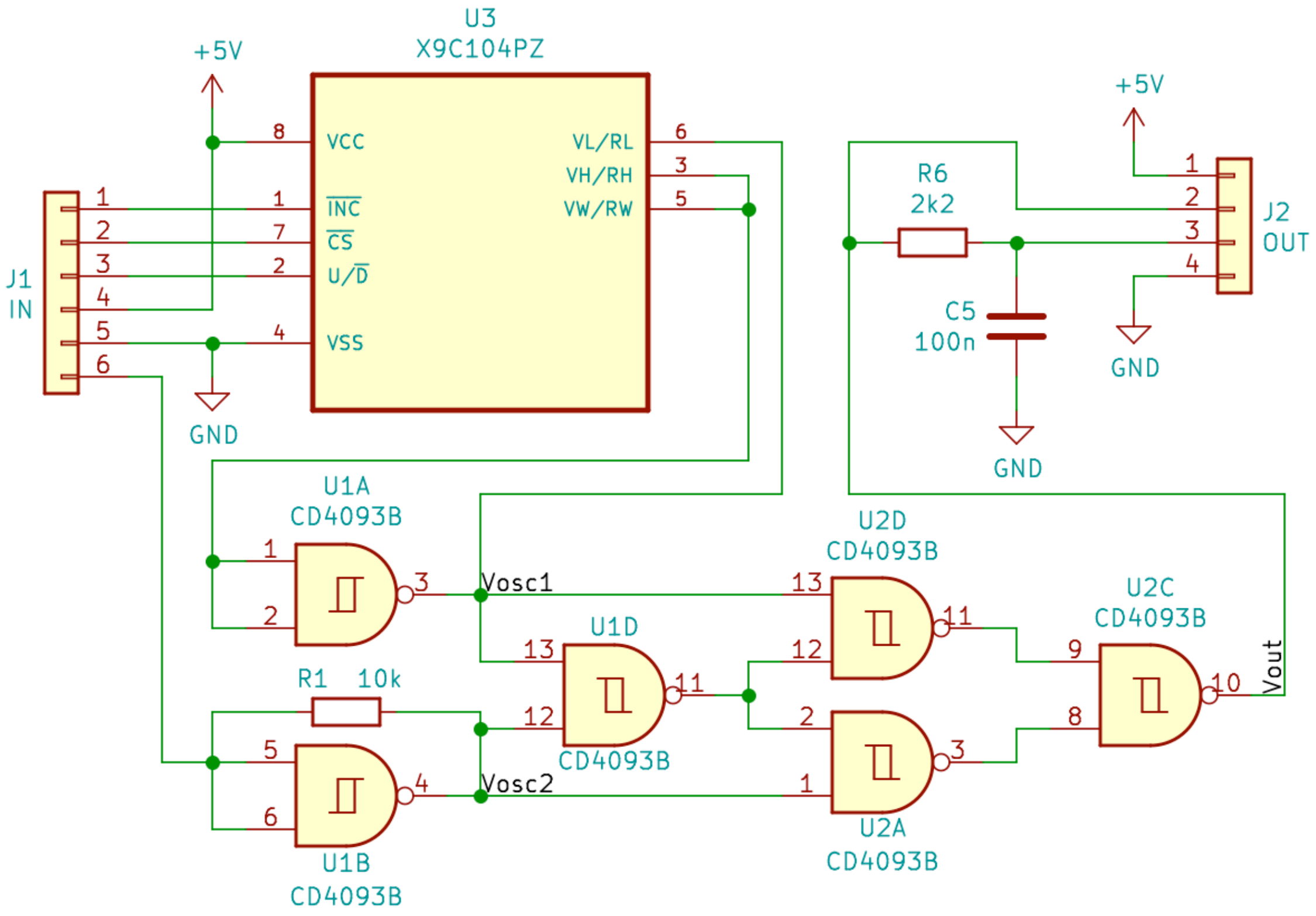
The schematic of the proposed device is presented in
Figure 2. The 6-pin connector J1 labeled “IN” is used to provide connections to:
The sensing plate used in our measurements was a 10 × 10 cm thin copper PCB square, but the functionality of the proposed device is not limited by the sensing plate design and size. The operating principle of digital oscillators is based on using the CD4093 Schmitt NAND gates (U1A for the secondary oscillator, U1B in the primary oscillator). They are connected to behave as NOT gates, feeding the output signal back to both inputs through a 10 k resistor in the primary oscillator or 10 k digital potentiometer X9C104 (U3) in the secondary oscillator. Both U1A and U1B have a ≈5 pF input capacitance (not visible in the schematic), which is being charged through the feedback resistor while their outputs are high. Once the input voltage reaches the high trigger threshold voltage, the output goes low and input capacitance begins to discharge through the feedback resistor. As the input voltage drops down to the low trigger threshold voltage, the output goes high again and the input capacitance begins to charge. Consequentially, the voltage at the output of U1A and U2B oscillates between the high and low level as a digital square wave signal. Its frequency depends on the feedback resistor and input capacitance values. As there is a sensing plate connected to the primary oscillator, any nearby grounded object will introduce additional capacitance and change its frequency. During the self-adjustment procedure, the value of the digital potentiometer U3 is set to equalize the frequency of the secondary oscillator to that of the primary one.
The primary oscillator is connected to the sensing plate and has a fixed 10 k
resistor in the feedback path. Any grounded object placed within the sensing range will introduce additional capacitance to this oscillator and change its frequency to a certain extent. The secondary oscillator has a digital potentiometer X9C104 (X9C104 Digitally Controlled Potentiometer datasheet:
https://www.renesas.com/us/en/document/dst/x9c102-x9c103-x9c104-x9c503-datasheet accessed on 20 December 2021) in the feedback path which allows for remote adjustment of its frequency. The value of this potentiometer is to set during the boot-up self-adjustment procedure, while there is no object present within the sensing range, aside from the static surroundings. The signals from the two oscillators are sent to a mixing stage, realized as an logical XOR structure. Both oscillators and mixing stage are realized using CD4093 Schmitt NAND gates (CD4093 CMOS Quad 2-Input NAND Schmitt Triggers datasheet:
https://www.ti.com/lit/ds/symlink/cd4093b.pdf accessed on 20 December 2021). The output form the mixing stage is filtered by a passive RC integrator to yield an average (DC) value of the output signal. The 4-pin connector J2 labeled “OUT” is used to output both filtered and unfiltered output signal, as well as power supply connections. Following the presented schematic a prototype of the proposed device has been designed and built in a through-hole technology.
3.2. Operating Principle
The proper operation of the proposed device has been verified in controlled laboratory conditions.
Figure 3a presents the measured waveforms when there is no object present and the sensor is self-adjusted. Both oscillators generate square waves at almost the same frequency, as measured around 2.7 MHz [
35]. There is an obvious asymmetry in the duty cycle of the generated signals as the low-level lasts for roughly one third of a period. This inevitably causes the signals to overlap in their high states during a short period in which the XOR structure should respond by going low. As the propagation delay and transition time impose a strong limit to the dynamic response of the XOR structure, it has no time to respond to such short overlaps. Therefore the output signal remains high as the signals are constantly out of phase. This phase alignment is a phenomenon which calls for further investigation, but is probably caused within the integrated circuit itself. A reasonable solution for this would imply using separate ICs for both oscillators, but this would introduce larger differences between them, compromising the self-adjustment procedure.
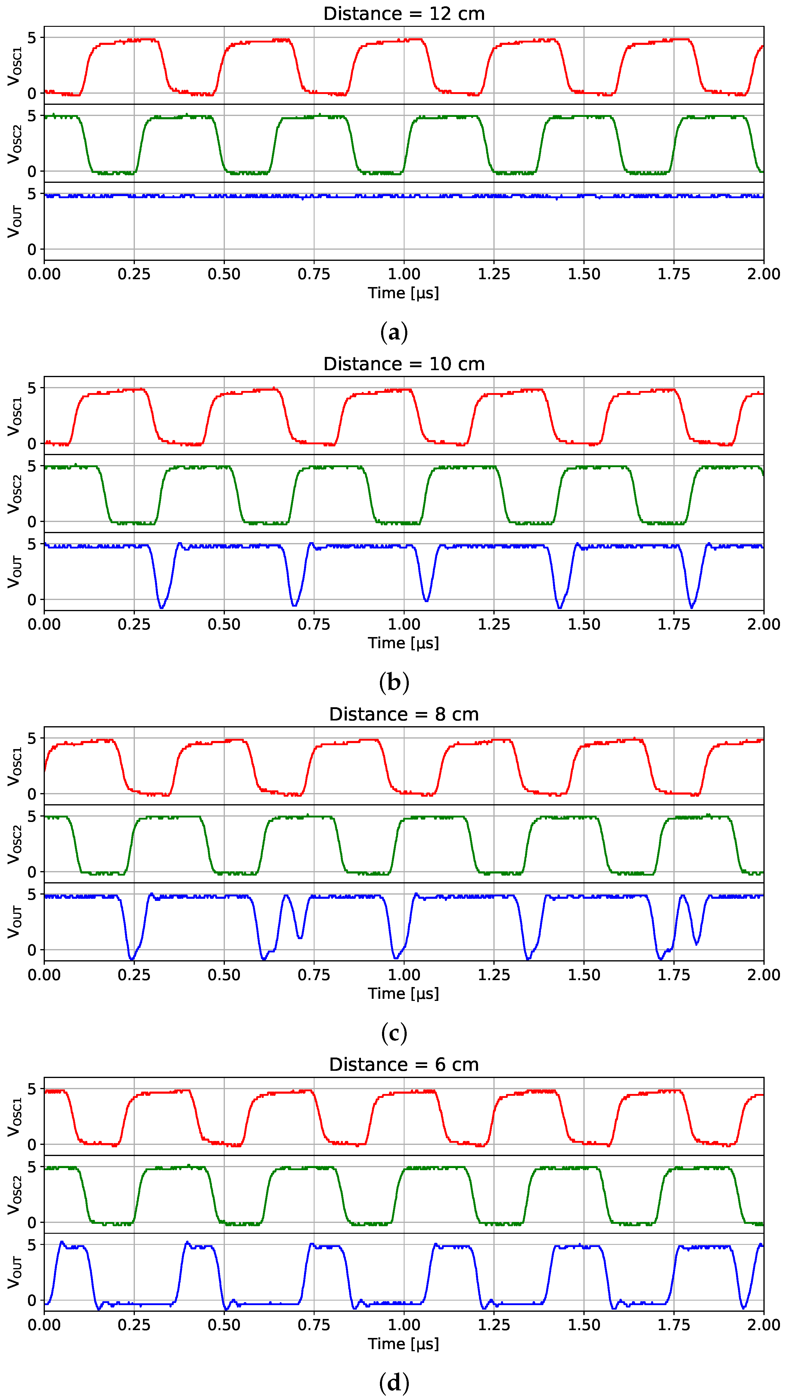
If an object is present within the sensing range (around 10 cm), additional capacitance is added to the primary oscillator, detuning its frequency. The physical basis for the range limitation of the proposed capacitive sensor lies in the ability to sense the additional capacitance introduced by a nearby object. This capacitance is added to the total capacitance in the sensing oscillator. The lumped capacitors are not used in the oscillators, as it has been proved in [
35] that the parasitic capacitance present between the pins of the IC and the PCB (≈20 pF) is large enough to generate oscillations with a 10 kOhm resistor in the feedback loop. This capacitance is well below the lower limit stated in the CD4093 datasheet, but allows for greater sensing range. Any minor ambiental capacitance introduced by a nearby object would detune the oscillator to a greater extent than if there were lumped capacitors in the oscillators. The general idea is to keep the overall capacitance in the oscillators at a lowest possible value in order to detect ambiental capacitance at maximum possible distance (range). It is the relative difference between the two oscillators’ frequency that functions as a main sensing mechanism.
This extends the duration of the overlapping high levels of the output signals, allowing the XOR structure to respond by going low despite the previously mentioned dynamic properties, as presented in
Figure 3b. This reduces the average output voltage obtained at the output of the passive RC filter/integrator, as presented in
Figure 4. Observed periodicity of the signals in
Figure 4 results from driving the sensor’s power supply by means of duty cycling, which decreased average power consumption. A more detailed discussion regarding the power consumption and optimization can be found in
Section 5.1. Bringing the object closer to the sensor further detunes the primary oscillator, thus extending the overlap of the high levels in the output signals,
Figure 3c,d. The duration of the low state at the output of the XOR structure increases, reducing the average (DC) value of the output voltage. The output voltage can never zero out, as the oscillators would have to be perfectly in phase and at the same frequency for this to happen. The waveforms observed are far from an ideal digital square wave due to the transition (rise/fall) times of the CD4096 IC (≈50 ns). Therefore they appear more of a trapezoidal shape. Furthermore, the propagation delay causes the output from XOR structure (blue waveform) to respond after approximately 100 ns.
5. Discussion
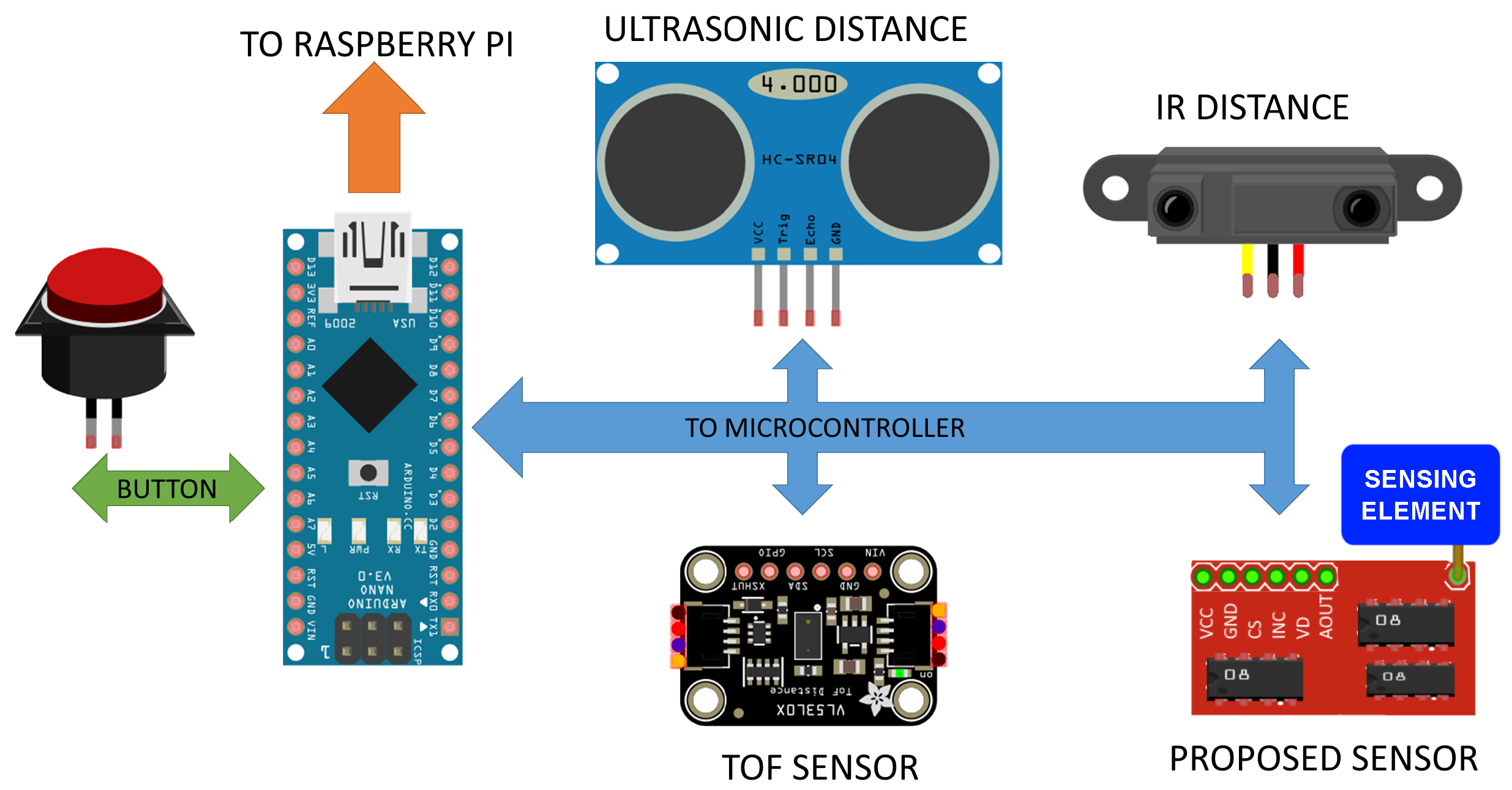
The main goal of this paper was to develop a proximity sensor with possible application in human–machine interaction and mobile robotics. To validate our hypothesis some limited trials originally aimed to benchmark distance sensors had to be performed. First of all, ability to accurately measure the distance of an object in its vicinity and secondary estimate usable sensor bandwidth.
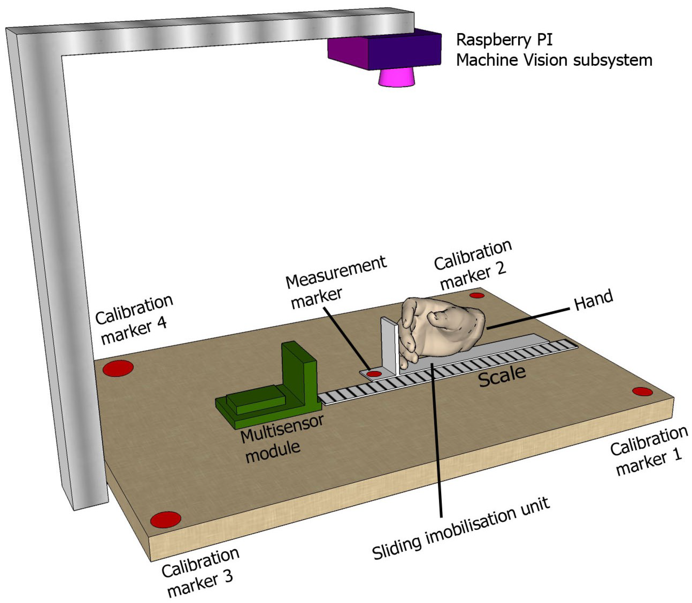
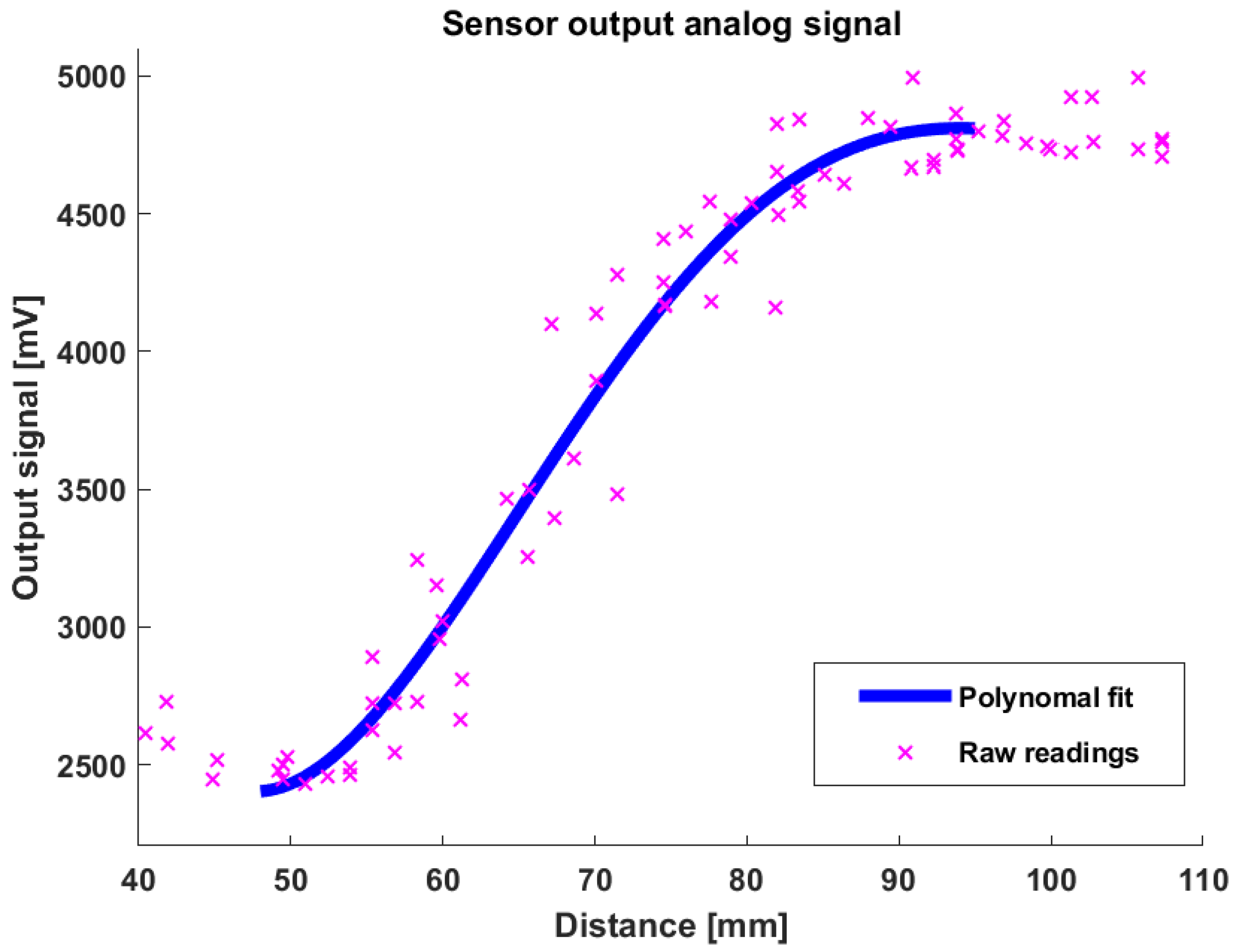
As described in previous sections, a computer vision system was employed for obtaining the referent measurement. In the first trial the output analog signal from the proposed sensor was compared with the referent distance for a total of 252 points with an intention of creating a distance measurement characteristics plot presented in
Figure 7. Non-linear characteristics of the proposed sensor are evident, where some similarities with the IR distance sensor are observable.
The sensor displays predictable behavior in ranges up to 10 cm, which can be described with a polynomial function. As the maximum output signal is reached (at distance around 10 cm) the output signal saturates and remains constant with increasing distance. Measured data for ranges up to 10 cm were used in second step which approximate voltage to distance relation. A second-order polynomial function showed to be an optimal fit to the training data and can be described using the following expression:
where
is sensor output voltage,
is the pedestal value, and
d is measured distance from the object itself.
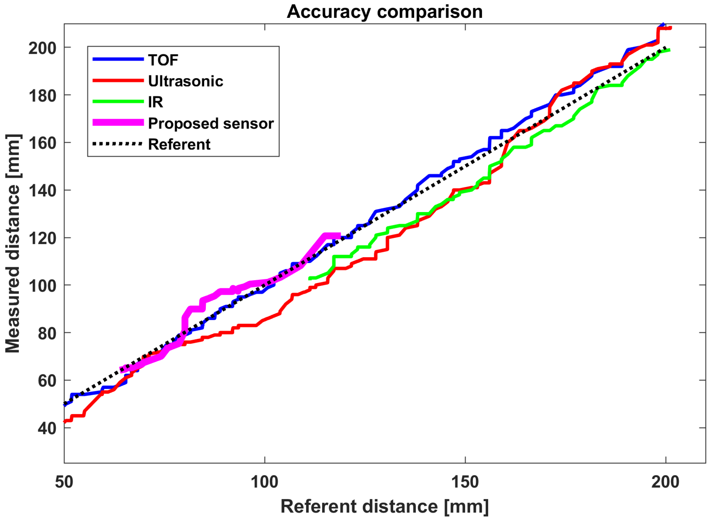
The second trial aimed to compare distances obtained by sensors included in the sensor subsystem with the distance estimated using the proposed sensor. The results are presented in
Figure 8, where it is evident that the sensor can estimate distances within its limited range (5–10 cm). More detailed comparison is presented in
Table 1, where the proposed sensor exhibits RMSE (Root Mean Square Error), MAE (Mean Absolute Error) and STD (Standard deviation) similar to other sensors used in the setup. As sensors used in our setup do offer different measuring ranges, results in
Figure 9 were cropped to the range of 5–20 cm, usual in HMI for this type of sensor application. TOF sensor exhibits superior performance regarding the RMSE and MAE, which was almost in range of our referent CV system. When compared to our proposed sensor, TOF is highly directional and may fail to detect an object in its vicinity, while requiring four times more power than our proposed sensor. Ultrasonic and IR sensors exhibit something bigger RMSE and AME than our proposed capacitive sensor, with significantly more power required for operation. As our intention was to use sensors out-of-the-box with standard libraries no additional tweaking has been performed. All applied sensors can benefit from additional (individual) calibration and digital linearization in a limited range which may reduce error in the observed range. Additionally, both IR and ultrasound are directional and cannot sense the entire 360° area around the sensor. Our proposed capacitive sensor offers the reasonable error of distance readings for applications where highly precise distance measurement is not primal while having the lowest average power consumption of any commercially available sensor that can operate in the same manner.
Both trials support our hypothesis that the proposed sensor can successfully detect the presence of the object in its vicinity and accurately estimate the distance within a limited range. A comparison of sensing range and measuring angle between all sensors used in the experiment is presented in
Table 2.
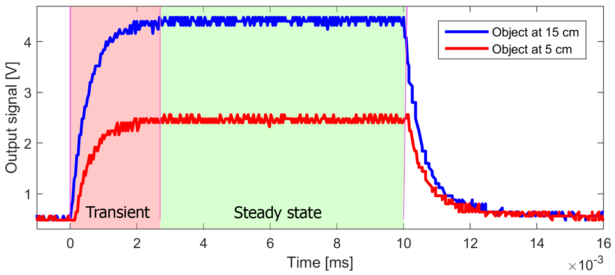
The third trial included a detailed analysis of sensors’ analog output signal, which aims to calculate sensors’ bandwidth and lay some recommendations for duty cycle timings. The output signal from the sensor was read by two-channel oscilloscope DS1102E (DS1102E Osciloscope product page:
https://www.rigolna.com/products/digital-oscilloscopes/1000/ accessed on 20 December 2021) with 100 MHz bandwidth and the ability to read up to 1 GSa/sec. Signal generator Rigol DG1022 (DG1022 signal waveform generatoor product page:
https://www.rigolna.com/products/waveform-generators/dg1000/ accessed on 20 December 2021) was used for generating square signals, utilized as both trigger and a power supply for the sensor. As maximal output current is not explicitly stated in the generator’s data sheet, the preliminary test shows that external source was not required, thus allowing the proposed sensor to be solely powered using signals generated by a signal generator itself. Power consumption is with more details discussed in the next subsection.
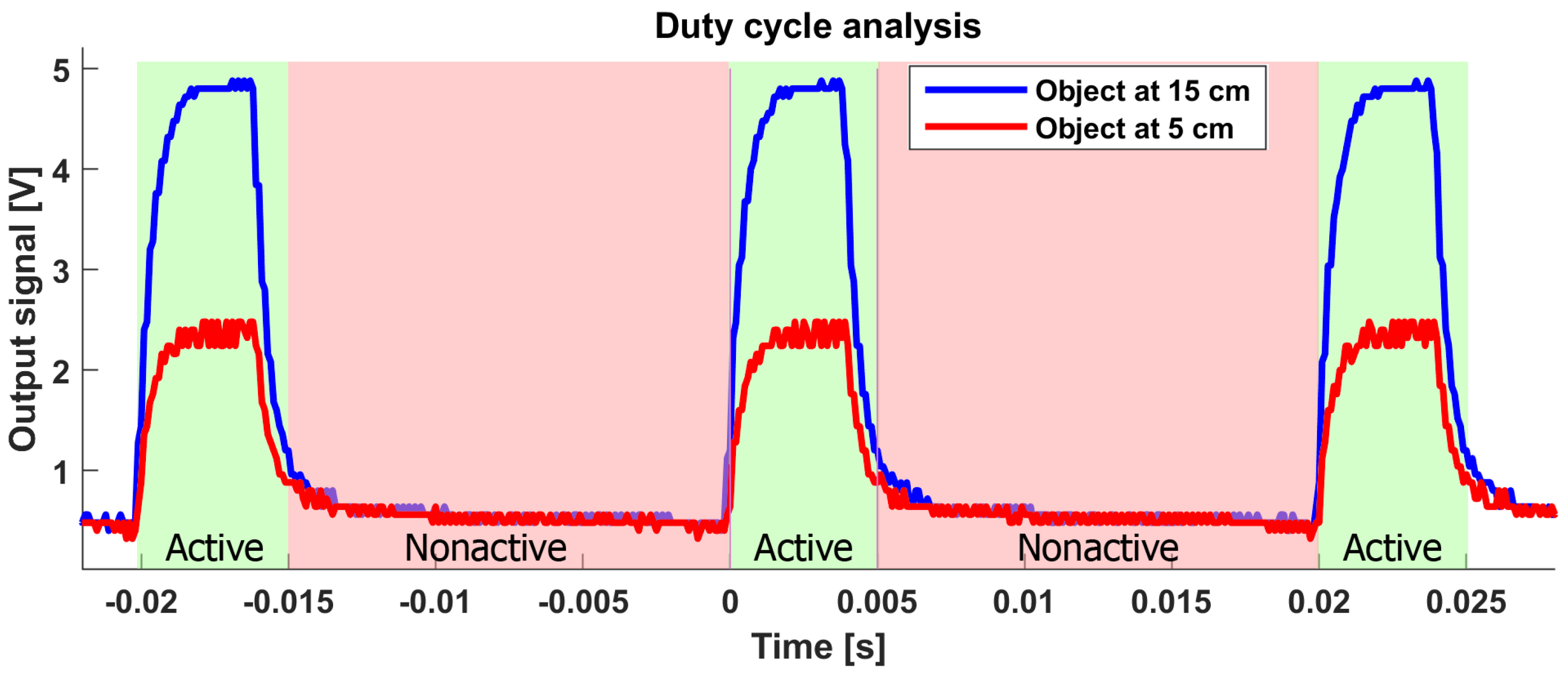
Square signals with a 50% duty cycle were input to the sensor, where analog output signal was recorded and analyzed using an oscilloscope for a range of input frequencies and object distances. The main task was to observe the transient part of the recorded signal and to estimate the minimal time required for signal settling (defined as when oscillations are inside 5% the settling value). Results are presented for both object placed at 5 cm and 15 cm from the sensor. Differences between settling times for both measurements are negligible and measuring around 2.6 ms.
5.1. Power Consumption
Settling times measured in the previous subsection lead us to a possibility to create a more power-efficient device. By means of minimizing the active duty cycle of the proposed sensor, average power consumption is consequently reduced. As reported in the literature, human self-paced movements for index fingers are within 3.3 Hz bandwidth [
42], thus proposed 50 Hz sampling rate is sufficient for recognizing complex hand gestures. This leads us to the conclusion that single time frame can last up for 20 ms. By a conservative estimation that active sensor time is 5 ms, 2.6 ms required for a transient response, and the rest for averaging several ADC readings leads us to active time lasting 5 ms. Thus, 50 Hz sampling with a 20 percent duty cycle was selected as optimal in our configuration. An oscillogram with the proposed 50 Hz rate and 20 percent duty cycle is presented in
Figure 10, where it is evident that the sensor’s output signal successfully stabilizes around settling time, thus allowing enough time for it to be successfully read by the ADC.
Active power consumption was measured using a shunt resistor and oscilloscope resulting between 2.4 and 4.9 mA, depending on object distance. This leads us to another estimation that in maximum power demanding mode and with optimal duty cycle sensor in average requires 0.98 mA when powered with 5 V input. When comparing to other devices implemented in sensor subsystem, proposed sensor uses significantly less power, averaging around 5 mW, as presented in
Table 1. This further emphasizes the possibility of utilizing the proposed sensor in battery powered applications, particularly in IoT scenarios.
The operating sensing range of the presented device exceeds values commonly found in similar capacitive sensing technologies, allowing them to evolve from tactile to contactless. What is more, the self-adjustment algorithm allows for effortless utilization of the proposed device in a wide variety of applications. For example, such a device could be integrated within a Smart Home touchless control panel as a novel sensing technology in the realm of such interfaces. This could provide a hygienic solution to overcome ongoing COVID-19 pandemic, while remaining cost- and energy-efficient. Such a solution is also extendable to various contactless interface applications, including ATM machine and elevator keypads. Within these applications, object’s presence is a key factor, instead of the exact distance of an object to the sensor. Therefore the proposed device is expected to be more resilient to harsh environmental conditions compared to other commonly used sensing technologies, such as infrared and ultrasonic [
18,
31,
43]. The proposed sensor could also be employed as a covert proximity alarm system at smart homes, banks, or museums, with no visible components. Limited distance measurement capabilities may even enable the device to be used as a contactless gesture recognition system using simple and intuitive hand gestures.


