Article

A Flexible and Low-Cost UHF RFID Tag Antenna for Blood Bag Traceability

by
Mohamed El Khamlichi
1,
Alejandro Alvarez-Melcon
2,*,
Otman El Mrabet
1,
Mohammed Ali Ennasar
1 and
Juan Hinojosa
3
1
System of Information and Telecommunications Laboratory (LaSIT), Faculty of Science, Abdelmalek Essaadi University, Tetouan 93000, Morocco
2
Department of Information and Communications Technology, Universidad Politécnica de Cartagena, 30202 Cartagena, Spain
3
Department of Electronics and Computer Engineering, Universidad Politécnica de Cartagena, 30202 Cartagena, Spain
*
Author to whom correspondence should be addressed.
Electronics 2022, 11(3), 439; https://doi.org/10.3390/electronics11030439
Submission received: 29 December 2021 / Revised: 27 January 2022 / Accepted: 30 January 2022 / Published: 1 February 2022

Abstract

:
A new low-profile flexible RFID tag antenna operating in the ultra-high frequency (UHF) European band (865 MHz–868 MHz) is proposed for blood bag traceability. Its structure combines inductive and capacitive parts with nested slots allowing for the achieving of conjugate impedance matching with the IC-chip. The whole electrical parameters of the environment (substrate, bag, and blood) were considered for the design of the tag antenna. A good agreement was obtained between the measurements and electromagnetic simulations for the input impedance of the tag antenna in the UHF band. A reading range close to 2.5 m was experimentally obtained. Therefore, this tag antenna could be effective and useful in future RFID systems for blood bag monitoring, thus improving patient safety in healthcare infrastructures.

1. Introduction

Automatic identification of objects using radio waves can be carried out using technologies such as radio frequency identification (RFID). This technology is becoming more and more popular in everyday life. It has been extensively used in many practical applications in Internet of Things (IoT) and has become essential for a set of applications including identification, localization, tracking, sensing, inventory control, and supply chain management [1,2,3,4,5,6,7].
In [8], it is reported that most medical errors are attributable to sample misidentification, adverse effects of medications, or incorrect blood transfusion, which are mainly caused by patient misidentification and/or human intervention errors. The use of RFID technology offers many benefits to the health system, especially with present-day staff shortages, and thus can enhance patient safety. Passive RFID technology working at ultra-high frequency (UHF) can be used in healthcare infrastructures. Possible applications include tracking of physiological parameters such as patient body temperature [9,10,11,12], blood glucose monitoring [13,14], real-time monitoring, and discrimination of breath anomalies [15], as well as monitoring of blood tubes [16,17] and bags [18,19,20,21,22,23,24] for the management of blood products [25,26,27].
The goal of this work is the monitoring of blood bags. The low cost and easy manufacturing of passive RFID tags have significant advantages in making them a good candidate for this application. Other important factors to be considered are reading range and flexibility. Among the available solutions [18,19,20,21,22,23,24], general-purpose commercial UHF RFID tags have reading ranges below 0.5 m when they are attached to blood bags [18], while the others vary from a few centimeters to 1.5 m for blood management systems operating in near- or far-fields [19,20,21,22,23,24]. These commercial and specific RFID tags are mainly of inductive dipole type to facilitate impedance matching with the capacitive IC-chip impedance, although some are based on traveling wave antenna [19] or the capacitive dipole type [24]. Except for three tags [19,22,23], most are flexible. In addition, many flexible tag antennas have been developed for purposes different from the one addressed in this paper [28,29,30,31,32,33,34,35]. Among them, those based on paper material [28,29], high-conductivity graphene assembly film (HCGAF) [30], inductive coupling loop [31], textile fabric and yarn [32,33], and PTFE and Kapton substrates [34,35] stand out. Except for the tag antennas printed on PTFE and Kapton substrates, which are low cost and have ideal physical, thermal, and electrical proprieties [36,37] for inexpensive practical blood bag monitoring, the other materials are not suitable for this application, since the paper and textile fabric and yarn are not resistant to mechanical and thermal stress. Moreover, HCGAF material, although strong, requires an expensive fabrication process and an inductive coupling loop using conductor wire, which can pierce the bag.
The best option for the traceability of many blood bags in different scenarios [25,26,27] (donation site, shipment to laboratory, inventory, shipment to hospital, etc.) are low-cost, flexible and far-field passive RFID tag antennas. However, the design of passive RFID tag antennas operating in far-field and UHF band is limited by the high values of the loss and dielectric permittivity of the blood, which prevent good impedance matching between the IC-Chip and the tag antenna and cause a reduction in the reading range due to the high absorption of the electromagnetic radiation produced by the blood.
In this paper, a new passive low-cost tag antenna covering the European (865 MHz–868 MHz) UHF band and exhibiting flexibility, reduced size, and large reading range for blood bag traceability is proposed. The designed UHF RFID tag antenna is fabricated on an adhesive, flexible, and resistant substrate of Kapton polyimide thin film (3MTM Kapton polyimide film tape 5413 amber) [37], thus allowing it to be easily molded and attached to blood bags. The tag antenna is designed to operate optimally in a real environment with a smaller size and larger reading ranges than the available solutions for blood bag traceability [18,19,20,21,22,23,24]. To achieve these goals, blood, the PVC bag, and the Kapton substrate were considered during its design. To overcome the problem of high values of loss and permittivity of the blood, the proposed RFID tag antenna includes inductive and capacitive parts with nested slots, which form an innovative structure. Good impedance matching between the NXP G2XM IC-chip [38] and the tag antenna in the presence of the blood is achieved by tuning the inductive and capacitive parts with nested slots in a flexible way, thus improving the reading range. This new tag antenna is expected to be of interest in future blood bag traceability systems and enhance patient safety in health infrastructures.

2. Proposed UHF RFID Tag Antenna

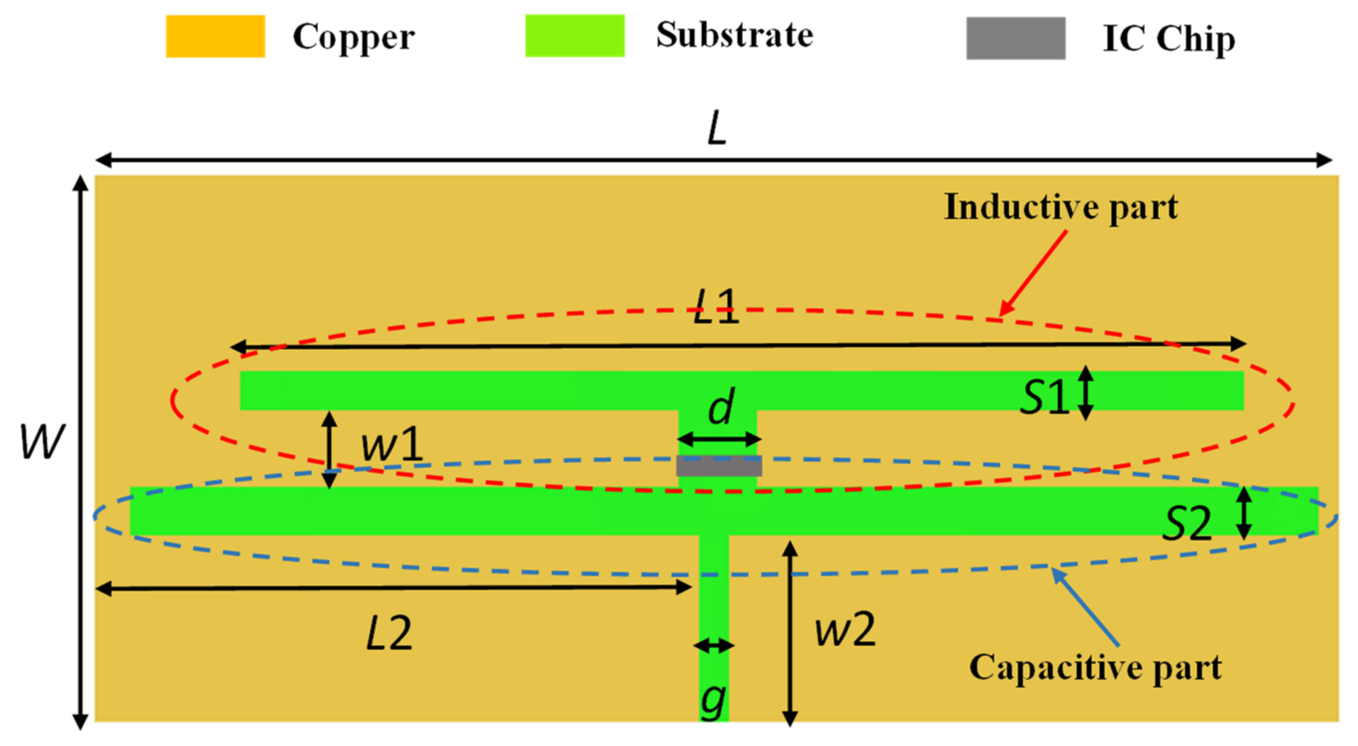
2.1. Antenna Structure

Figure 1 displays the structure and dimensions of the UHF RFID tag antenna. It is based on an inductive and capacitive part with nested slots. The dimension of the nested slot for the inductive part is L 1 × S 1 . The capacitive part of the tag antenna is introduced through the vertical slot g × W 2 and the horizontal slot 2 × L 2 + g × S 2 . The inductive part is separated from the capacitive part by the gap W 1 × d . The IC-chip is mounted across the gap W 1 × d between the inductive and capacitive part. The proposed tag antenna with slots provides an excellent impedance matching on high-permittivity materials, such as blood, and a reduced size. When the antenna operates in close proximity to the blood, the high value of the relative permittivity has the effect of reducing the size of the antennas, thus leading to structures with low radiation efficiency. Consequently, the basic idea was to start the design with a capacitive dipole structure (g, S2, L2). However, using only a capacitive slot leads to a configuration that is too large. This is because a capacitive antenna will need extra length to introduce an inductive component that can compensate for the capacitive impedance of the RFID IC-chip. In this work, we introduced another slot (d, S1, L1) that acts as an inductive part in parallel with the capacitive slot to maintain a compact design.
The tag antenna is realized by means of the following elements: an adhesive and flexible Kapton polyimide substrate of a thickness of 70 μm [37], an adhesive copper sheet (pre-cut copper tape) with a thickness of 35 μm, and a NXP G2XM IC-chip with TSSOP8 packaging [38]. The electrical characteristics of the Kapton polyimide between 865 MHz–868 MHz (UHF European band) are ε r = 3.1 and tanδ = 0.0015 [17,37]. The power threshold sensitivity of the NXP G2XM IC-chip is P c = 17 dBm [38].

2.2. Design and Optimization

The tag antenna design was performed simulating the scenario shown in Figure 2. The tag is placed on a bag, which is simulated by means of a PVC layer ( ϵ r = 2.2 ) of 160 × 130 mm2 with a thickness of 0.4 mm. The whole set is placed above a rectangular box simulating the blood. This box has the same dimensions as the bag, except for the thickness, which is 20 mm. The permittivity and conductivity ( ϵ r = 61.2 and σ = 1.12 S/m at 867 MHz) of the blood used in the simulation model were obtained from [17].
The commercial electromagnetic simulator CST Microwave Studio Suite® was used for the design, analysis, and optimization of the proposed tag. The tag attached to the blood bag is drawn in the modeler as shown in Figure 2, and all its element parameters (dimensions, substrate permittivity, blood permittivity, and thickness substrate), including the IC chip, are defined. The real and imaginary parts of the complex chip impedance (Zc = 28 – j 157 Ω) are respectively specified by means of a discrete port and a lumped RLC series element. The discrete port and the lumped RLC series element are situated across the gap d between the two pads, in the same place as the IC chip (Figure 1). Then, the simulation is started from the transient solver. Once the simulation is finished, different parameters such as impedance, reflection coefficient, and gain can be analyzed.
The design and optimization of the antenna were carried out in three steps. In a first step, the effects of the design parameters of the tag antenna in a real environment (blood, PVC bag, Kapton substrate) where the tag should operate were studied from several simulations. In a second step, the parameters of the proposed tag antenna were optimized in the UHF European band (865 MHz–868 MHz). Finally, in the last step, the length of the horizontal slot L1 and the width g of the vertical slot were finely tuned to match the conjugate impedance of the RFID tag antenna with the IC-chip impedance ( Z C = 28 j 157   Ω at 867 MHz) to avoid undesired reflections, realize a good power transfer, and obtain a large reading range. The other parameters (S1, W1, d, L2, S2, W2) are fixed during the final impedance optimization step with the IC-chip. The tuning is achieved by minimizing the power reflection coefficient:
Γ = Z a Z C * Z a + Z C
where Z a and Z C correspond, respectively, to the input complex impedance of the tag antenna and the complex impedance of the IC chip. The asterisk denotes a complex conjugate. Table 1 lists the optimized parameters of the tag antenna.

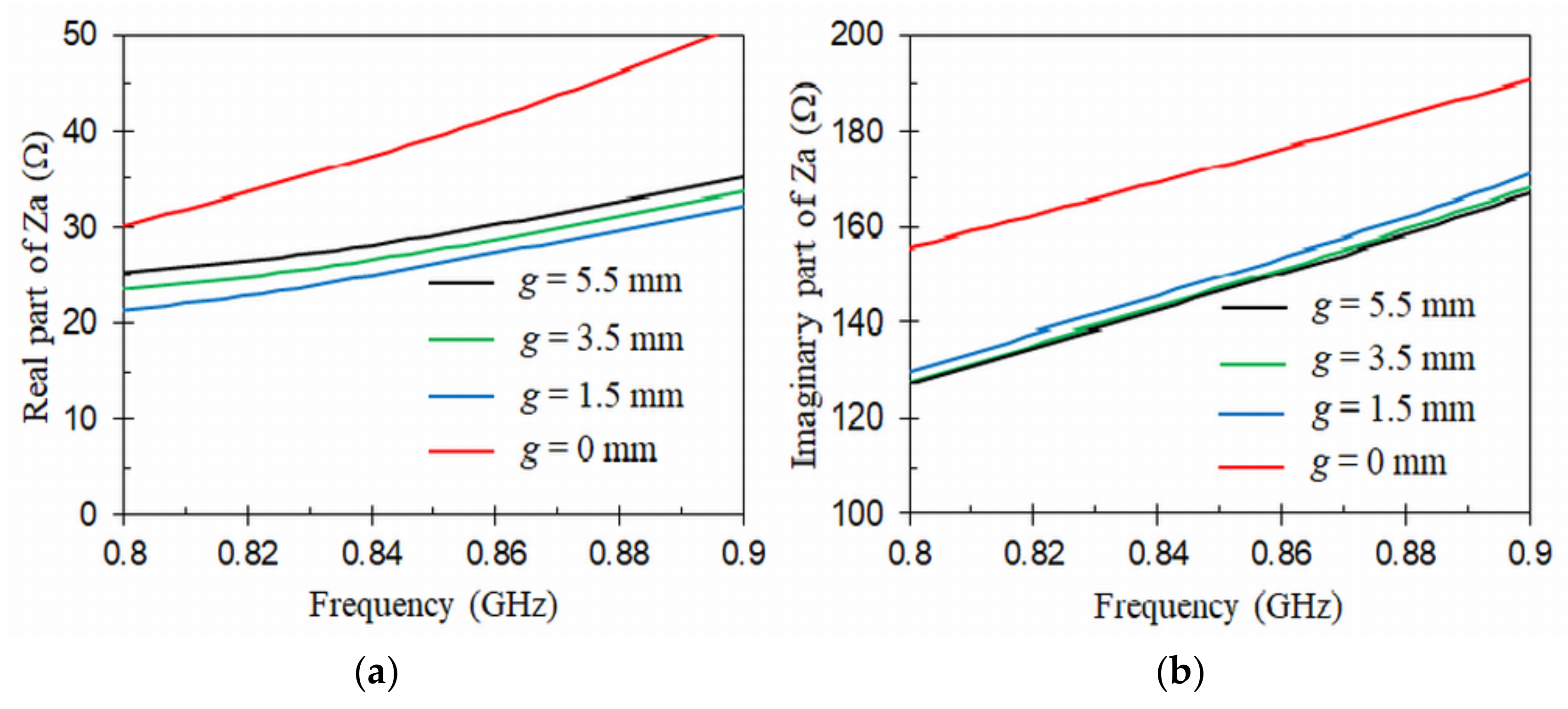
2.3. Parametric Study

Figure 3 and Figure 4 show the simulated input impedance ( Z a ) of the UHF RFID tag antenna as a function of frequency (0.8 GHz – 0.9 GHz) for different values of nested slot length L1 (39.5 mm – 45.5 mm) and vertical slot width g (0 mm – 5.5 mm), respectively. It should be noted that when one parameter (L1 or g) was varied, the others were kept equal to the values indicated in Table 1. As can be seen in Figure 3, the real and imaginary parts of the input impedance increase as the length L1 goes longer from 39.5 mm to 45.5 mm, while it decreases as the width g grows from 0 to 5.5 mm in Figure 4. From these results, it can be observed in Figure 3b that the reactance of the UHF RFID tag antenna is positive (inductive type), as it is required to accomplish a good matching condition with the IC-chip. In addition, Figure 4b displays that the introduction of the vertical capacitive slot g substantially lowers the value of the reactance. This shows that the capacitive slot is effective in the compensation for a too large inductance caused by the presence of the blood, by introducing an additional capacitive behavior. Therefore, the parameters L1 and g can be used to fine tune the UHF RFID tag antenna input impedance and provide optimum control on the matching condition with the IC-chip.

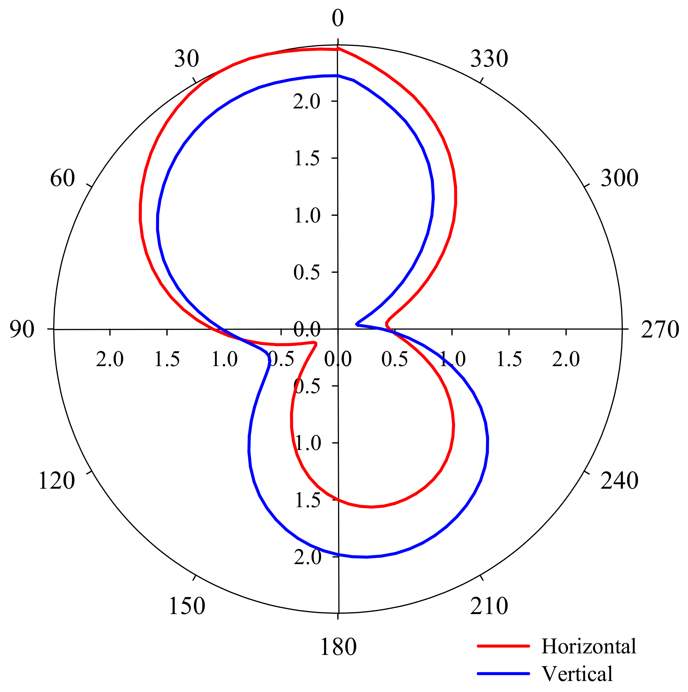
2.4. Radiation Diagram

Figure 5 displays the simulated radiation patterns in the E and H planes for the proposed tag antenna attached on a full blood bag. The simulations were carried out for the optimized tag (Table 1) at the center frequency of the UHF band: f c = 867 MHz. Data were normalized to the maximum value of the 3D pattern. As can be seen in Figure 5, the radiation patterns of the antenna are quasi-omnidirectional, typical of small-size planar antennas. Moreover, the tag exhibits linear polarization. As can be observed, the radiation reaches its maximum in both planes at 18°. This slight tilt with respect to the broadside direction is due to the asymmetry introduced by the feeding point position, and the asymmetric position of the tag with respect to the blood bag. This will be confirmed in the next section by experiments.

3. Measurement Results and Discussion

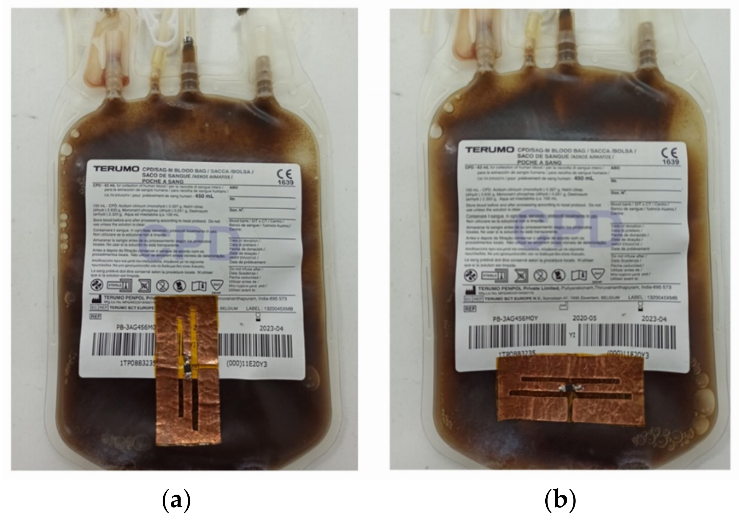
3.1. Fabrication and Measurement Setups

The proposed flexible UHF RFID tag antenna (Figure 1) was fabricated with the dimensions included in Table 1 using a laser prototyping system (LPKF Protolaser S) and then characterized from a vector network analyzer (Rhode & Schwarz ZVB 20). In the first step, the UHF RFID tag antenna input impedance was measured by means of a port-extension technique as in [17,39]. Then, in the second step, the reading range was obtained in free space similarly to [40,41]. Both experimental setups are depicted in Figure 6. In Figure 6b we can see a photograph of the antenna slightly bent in a blood bag. We have verified in experiments that a slight bending of the antenna has little influence on its performance. The reading range of the proposed UHF RFID tag antenna placed on the blood bag was measured in horizontal and vertical positions (Figure 7). The measurements were realized with a reader output power of 1 W.

3.2. Input Impedance and Power Reflection Coeficient Measurements
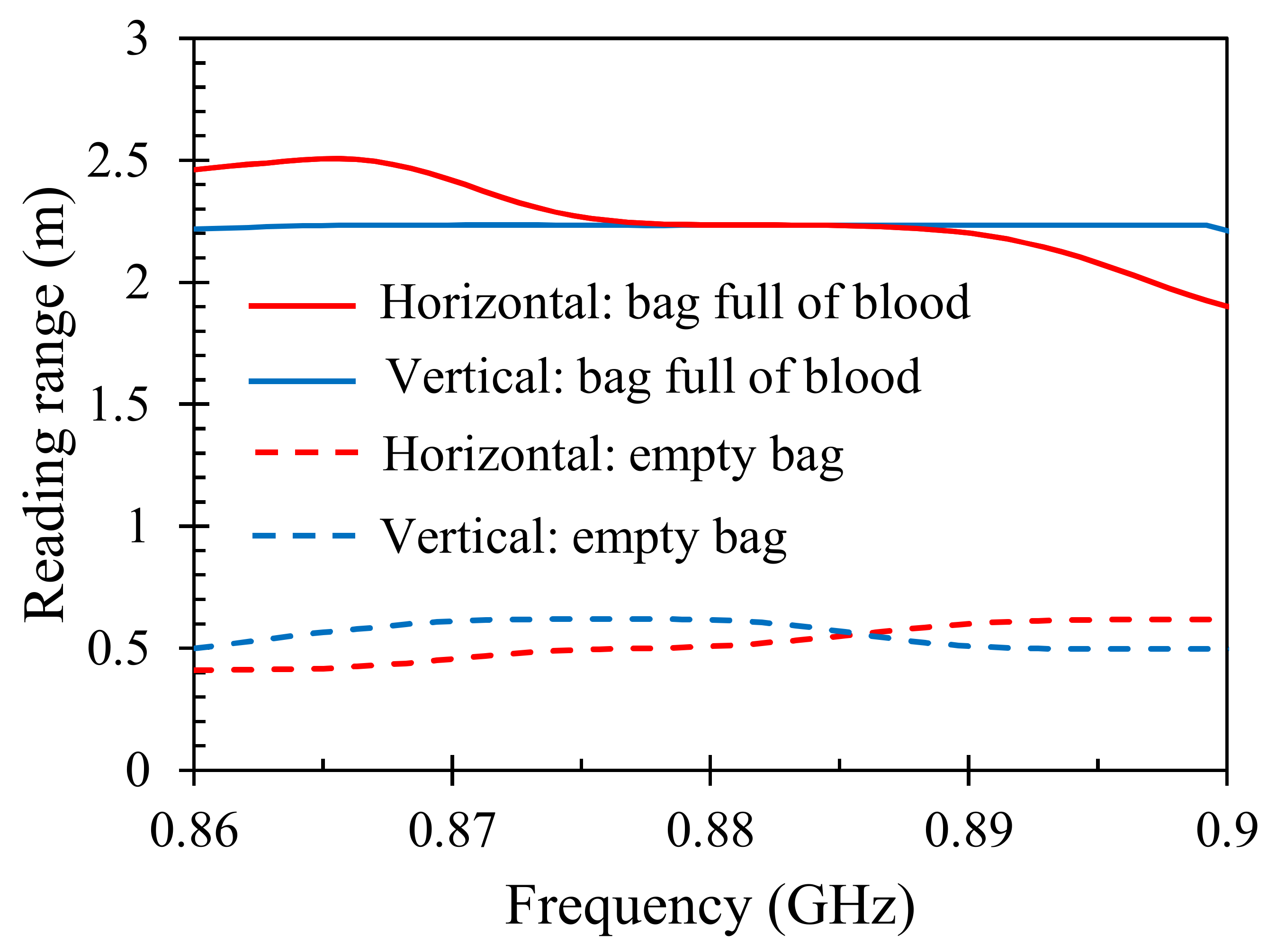
Figure 8 displays the simulations and measurements of the input impedance for the proposed UHF RFID tag antenna placed on a blood bag. The insets included in the graphs detail the values of the real and imaginary parts of the input impedance from 0.86 GHz to 0.96 GHz. As can be seen, the measured results of the real and imaginary parts of the input impedance are in good agreement with the simulated data. The measured input impedance at 867 MHz is Z a = 30 + j 169   Ω , which is comparable to the conjugate of the IC-chip Z C = 28 j 157   Ω . The mismatch is mainly due to negative mounting and handling effects, since the tag antenna becomes wrinkled on the blood bag, as can be seen in Figure 7.
Figure 9 shows the simulations and measurements of the power reflection coefficient (1) for the proposed tag antenna placed on the blood bag. As can be seen in Figure 9, simulations and measurements are in good agreement and confirm good impedance matching between the tag antenna and the IC chip in the UHF European band (865 MHz–868 MHz). In particular, the antenna achieves Return Losses around 12 dB at the center frequency (867 MHz).

3.3. Reading Range

The reading ranges for the proposed UHF RFID tag antenna placed horizontally and vertically on the blood bag, which were measured in a natural environment from 0.86 GHz to 0.9 GHz, are shown in Figure 10. As can be seen, a maximum reading range of 2.22 m or 2.5 m is achieved as the tag is respectively placed vertically or horizontally on the bag full of blood, while it is less than 0.7 m when the tag is located on an empty bag.
Figure 11 shows the reading patterns at 867 MHz of the designed tag attached horizontally and vertically on the blood bag. A maximum reading range of 2.5 m and 2.22 m is obtained at the angle of 18° when the tag is respectively placed in the horizontal and the vertical position on the blood bag. The tilt in the reading range pattern is due to inevitable misalignment between the reader and the UHF RFID tag antenna during the process of measurement. Lower reading ranges in the backward direction are due to higher absorption of the electromagnetic waves when traveling through the blood bag.

3.4. Comparison with Other Designs

Table 2 provides a comparison between several previously reported designs and the proposed UHF RFID tag antenna for blood bag traceability in terms of flexibility, antenna type, operating frequency range, output power of the RFID reader, reading range and 2D size. The proposed RFID tag antenna design reaches a maximum reading range with a small size as compared to the other designs listed in Table 2. In addition, the designs reported in [19,22,23] are not flexible; hence, they are not suitable to be attached to blood bags in an easy way. Table 2 also reveals that the proposed RFID tag antenna is the only design that combines inductive and capacitive coupling elements to obtain the conjugate impedance of the IC-chip. Therefore, the proposed RFID antenna can simultaneously achieve a high reading range with a suitable small electrical size as compared to prior designs, and can be a good candidate for blood bag traceability applications.

3.5. Effects of UHF Electromagnetic EM Fields on a Blood Bag

The proposed tag antenna for the traceability of blood bags could be used in the health system only if the blood contained in the bag is not affected by negative effects. The negative effects on the blood for this application could be due to the overheating that would be produced by the electromagnetic fields of the RFID reader. This would involve blood coagulation, since the electric conductivity decreases [42]. Should this occur, there would be no choice but to discard the blood bag from the system. However, it has been found in previous studies that these negative effects do not occur during a typical reading cycle of the UHF RFID reader [43,44].

4. Conclusions

In this paper, a novel high-performance flexible tag antenna with a reduced size for blood bag traceability using the UHF RFID system is proposed. Its structure is based on inductive and capacitive parts with nested slots allowing for good conjugate impedance matching with the IC-chip in the presence of the blood. The designed UHF RFID tag antenna was fabricated on an adhesive, low-profile, and flexible substrate of Kapton polyimide by means of a fast and low-cost prototyping technique. In this way, it can be easily molded and attached to the blood bags. The measured results showed that the proposed tag antenna attached to a blood bag exhibits a reading range close to 2.5 m in the European (865 MHz–868 MHz) UHF band. This flexible tag antenna can be useful for the design of new blood bag traceability systems using RFID UHF technology to improve patient safety and the reliability of healthcare infrastructures.

Author Contributions

M.E.K. contributed to the design, fabrication, and characterization of the proposed tag antenna. He participated in the manuscript writing. A.A.-M. contributed to the state-of-art by identifying the original design of the tag antenna. He also participated in the manuscript writing and the characterization of the tag antenna. O.E.M. is M.E.K.’s research director and contributed to the design of the UHF tag antenna. The analysis and design phases of this work were provided by M.A.E. and J.H. participated in the manuscript writing and data analysis. All authors have read and agreed to the published version of the manuscript.

Funding

The authors thank the support grants of the Agencia Estatal de Investigación of Spain (ref: PID2019-103982RB-C42/AEI/10.13039/501100011033) and the Moroccan Ministry of Higher Education (MESRSFC) and the CNRST (ref: PPR2/2015/36).

Conflicts of Interest

The authors declare no conflict of interest.

References

  1. Zhu, X.; Mukhopaddhyay, S.K.; Kurata, H. Review of RFID technology and its managerial application in different industries. J. Eng. Technol. Manag. 2012, 29, 152–167. [Google Scholar] [CrossRef]
  2. Zaid, J.; Abdulhadi, A.E.; Denidni, T.A. Miniaturized multi-port microstrip patch antenna using metamaterial for passive UHF RFID-tag sensor applications. Sensors 2019, 19, 1982. [Google Scholar] [CrossRef] [Green Version]
  3. Hussain, M.; Amin, Y.; Lee, K.G. A compact and flexible UHF RFID tag antenna for massive IoT devices in 5G system. Sensors 2020, 20, 5713. [Google Scholar] [CrossRef] [PubMed]
  4. Mezzanotte, P.; Palazzi, V.; Alimenti, F.; Roselli, L. Innovative RFID sensors for internet of things applications. IEEE J. Microw. 2021, 1, 55–65. [Google Scholar] [CrossRef]
  5. Andrade, L.; Figueiredo, J.; Tlemçani, M. A new RFID-identification strategy applied to the marble extraction industry. Electronics 2021, 10, 491. [Google Scholar] [CrossRef]
  6. Sharif, A.; Yan, Y.; Ouyang, J.; Chattha, H.T.; Arshad, K.; Assaleh, K.; Alotabi, A.A.; Althobaiti, T.; Ramzan, N.; Abbasi, Q.H.; et al. Uniform Magnetic Field Characteristics Based UHF RFID Tag for Internet of Things Applications. Electronics 2021, 10, 1603. [Google Scholar] [CrossRef]
  7. Chung, Y.; Berhe, T. Long-range UHF RFID tag for automotive license plate. Sensors 2021, 21, 2521. [Google Scholar] [CrossRef]
  8. Lippi, G.; Chiozza, L.; Mattiuzzi, C.; Plebani, M. Patient and sample identification. Out of the maze? J. Med. Biochem. 2017, 36, 107–112. [Google Scholar] [CrossRef]
  9. Amendola, S.; Bovesecchi, G.; Palombi, A.; Coppa, P.; Marrocco, G. Design, calibration and experimentation of an epidermal RFID sensor for remote temperature monitoring. IEEE Sens. J. 2016, 16, 7250–7257. [Google Scholar] [CrossRef]
  10. Camera, F.; Miozzi, C.; Amato, F.; Occhiuzzi, C.; Marrocco, G. Experimental assessment of wireless of axilla temperature by means of epidermal battery-less RFID sensors. IEEE Sens. Lett. 2020, 4, 6002304. [Google Scholar] [CrossRef]
  11. Camera, F.; Marrocco, G. Electromagnetic-based correction of bio-integrated RFID sensors for reliable skin temperature monitoring. IEEE Sens. J. 2021, 21, 421–429. [Google Scholar] [CrossRef]
  12. Occhiuzzi, C.; Parrella, S.; Camera, F.; Nappi, S.; Marrocco, G. RFID-based dual-chip epidermal sensing platform for human skin monitoring. IEEE Sens. J. 2021, 21, 5359–5367. [Google Scholar] [CrossRef]
  13. Xiao, Z.; Chen, X.; Chen, S.; Zhang, Z.; Zhang, H.; Wang, J.; Huang, Y.; Zhang, P.; Zheng, L.; Min, H. An implantable RFID sensor tag toward continuous glucose monitoring. IEEE J. Biomed. Health Inform. 2015, 19, 910–919. [Google Scholar] [CrossRef] [PubMed]
  14. Gao, M.; Qiang, T.; Ma, Y.; Liang, J.; Jiang, Y. RFID-based microwave biosensor for non-contact detection of glucose solution. Biosensors 2021, 11, 480. [Google Scholar] [CrossRef]
  15. Caccami, M.C.; Mulla, M.Y.S.; Occhiuzzi, C.; Di Natale, C.; Marrocco, G. Design and experimentation of a batteryless on-skin RFID graphene-oxide sensor for the monitoring and discrimination of breath anomalies. IEEE Sens. J. 2018, 18, 8893–8901. [Google Scholar] [CrossRef]
  16. Lin, Y.F.; Liao, C.T.; Chen, H.M.; Jiang, Z.D. Compact folded square-loop antenna for reading near-field RFID tags in blood sample tracking system. Electron. Lett. 2017, 53, 1627–1628. [Google Scholar] [CrossRef]
  17. Khamlichi, M.E.; Alvarez-Melcon, A.; Mrabet, O.E.; Ennasar, M.A.; Hinojosa, J. Flexible UHF RFID Tag for Blood Tubes Monitoring. Sensors 2019, 19, 4903. [Google Scholar] [CrossRef] [Green Version]
  18. Ibrahim, G.T.; Dutko, M.J. Tracking blood units in medical centers using passive UHF RFID systems. In Proceedings of the American Society for Engineering Education Annual Conference & Exposition, Seattle, WA, USA, 14–17 June 2015; pp. 1–14. [Google Scholar]
  19. Jeong, M.G.; Lee, W.S. A smart blood bag management system using a load-integrated U-shaped near-field RFID antenna array. IEEE Trans. Antennas Propag. 2019, 67, 1837–1843. [Google Scholar] [CrossRef]
  20. Fanti, A.; Secci, R.; Boi, G.; Casu, S.; Casula, G.A.; Mazzarella, G.; Montisci, G. A polycarbonate RFID tag for blood chain tracking. In Proceedings of the IEEE International Symposium on Antennas and Propagation and USNC-URSI Radio Science Meeting, Vancouver, BC, Canada, 19–24 July 2015; pp. 356–357. [Google Scholar]
  21. Choi, J.; Jeon, B.; Chung, Y.; Yeo, J. Design of a UHF RFID tag antenna for RFID-based blood-bag management system. In Proceedings of the International Symposium on Antennas and Propagation (ISAP), Jeju, Korea, 25–28 October 2011; pp. 712–714. [Google Scholar]
  22. Zaric, A.; Cruz, C.C.; De Matos, A.; Da Silva, M.; Costa, J.R.; Fernandes, C.A. RFID-based Smart blood stock system. IEEE Antennas Propag. Mag. 2015, 57, 54–65. [Google Scholar] [CrossRef] [Green Version]
  23. Khamlichi, M.E.; Mrabet, O.E.; Alvarez-Melcon, A. A ground slotted UHF tag antenna for blood bags monitoring. In Proceedings of the 19th Mediterranean Microwave Symposium (MMS), Hammamet, Tunisia, 31 October–2 November 2019. [Google Scholar]
  24. Sharif, A.; Ouyang, J.; Yan, Y.; Raza, A.; Imran, M.A.; Abbasi, Q.H. Low-cost inkjet-printed RFID tag antenna design for remote healthcare applications. IEEE J. Electromagn. RF Microw. Med. Biol. 2019, 3, 261–268. [Google Scholar] [CrossRef] [Green Version]
  25. Hohberger, C.; Davis, R.; Briggs, L.; Gutierrez, A.; Veeramani, D. Applying radio-frequency identification (RFID) technology in transfusion medicine. Biologicals 2012, 40, 209–213. [Google Scholar] [CrossRef] [PubMed]
  26. Kiruthika, S.; Sakthi, P.; Kaviya, M.; Vishnupriya, S. Blood bank monitoring and blood identification system using IoT device. Ann. Rom. Soc. Cell Biol. 2021, 25, 182–192. [Google Scholar]
  27. Pradhan, N.R.; Singh, A.P.; Kumar, V. Blockchain-enable traceable, transparent transportation system for blood bank. In Advances in VLSI, Communication, and Signal Processing; Springer: Singapore, 2021; pp. 313–324. [Google Scholar]
  28. Islam, M.T.; Alam, T.; Yahya, I.; Cho, M. Flexible radio-frequency identification (RFID) tag antenna for sensor applications. Sensors 2018, 18, 4212. [Google Scholar] [CrossRef] [PubMed] [Green Version]
  29. Kim, S. Inkject-printed electronics on paper for RF identification (RFID) and sensing. Electronics 2020, 9, 1636. [Google Scholar] [CrossRef]
  30. Zhang, B.; Zhang, C.; Wang, Y.; Wang, Z.; Liu, C.; He, D.; Wu, Z.P. Flexible anti-metal RFID tag antenna based on high-conductivity graphene assembly film. Sensors 2021, 21, 1513. [Google Scholar] [CrossRef] [PubMed]
  31. Moraru, A.; Ursachi, C.; Helerea, E. A new washable UHF RFID tag: Design, fabrication and assessment. Sensors 2020, 20, 3451. [Google Scholar] [CrossRef]
  32. Byondi, F.K.; Chung, Y. UHF RFID conductive fabric tag design optimization. Sensors 2021, 21, 5380. [Google Scholar] [CrossRef]
  33. Benouakta, S.; Hutu, F.D.; Duroc, Y. Strechable textile yarn based on UHF RFID helical tag. Textiles 2021, 1, 547–557. [Google Scholar] [CrossRef]
  34. Erman, F.; Hanafi, E.; Lim, E.H.; Mahyiddin, W.A.W.M.; Harun, S.W.; Umair, H.; Soboh, R.; Makmud, M.Z.H. Miniature compact folded dipole for metal mountable UHF tag antenna. Electronics 2019, 8, 713. [Google Scholar] [CrossRef] [Green Version]
  35. Wagih, M.; Wei, Y.; Komolafe, A.; Torah, R.; Beeby, S. Reliable UHF long-range textile-integrated RFID tag based on a compact flexible antenna filament. Sensors 2020, 20, 3435. [Google Scholar] [CrossRef]
  36. Rogers RT/Duroid Laminates: RT/Duroid® Laminates-Rogers Corporation. Available online: https://rogerscorp.com/advanced-electronics-solutions/rt-duroid-laminates (accessed on 21 December 2021).
  37. Kapton FN. Available online: https://www.dupont.com/content/dam/dupont/amer/us/en/products/ei-transformation/documents/EI-10142-Kapton-Summary-of-Properties.pdf (accessed on 21 December 2021).
  38. NXP Semiconductor. Available online: https://www.nxp.com/docs/en/data-sheet/SL3ICS1002_1202.pdf (accessed on 21 December 2021).
  39. Qing, X.; Goh, C.K.; Chen, Z.N. Impedance characterization of RFID tag antennas and application in tag co-design. IEEE Trans. Microw. Theory Tech. 2009, 57, 1268–1274. [Google Scholar] [CrossRef]
  40. Colella, R.; Catarinucci, L.; Coppola, P.; Tarricone, L. Measurement platform for electromagnetic characterization and performance evaluation of UHF RFID tags. IEEE Trans. Instrum. Meas. 2016, 65, 905–914. [Google Scholar] [CrossRef]
  41. Ennasar, M.A.; Mrabet, O.E.; Mohamed, K.; Essaaidi, M. Design and characterization of a broadband flexible polyimide RFID tag sensor for NaCl and sugar detection. PIER C 2019, 94, 273–283. [Google Scholar] [CrossRef] [Green Version]
  42. Panescu, D.; Webster, J.G. Effects of changes in electrical and thermal conductivities on radiofrequency lesion dimensions. In Proceedings of the 19th Annual Conference of the IEEE Engineering in Medicine and Biology Society, Chicago, IL, USA, 30 October–2 November 1997; pp. 154–156. [Google Scholar]
  43. Otin, R. Numerical study of the thermal effects induced by a RFID antenna in vials of blood plasma. Prog. Electromagn. Res. 2011, 22, 129–138. [Google Scholar] [CrossRef] [Green Version]
  44. Fanti, A.; Casu, S.; Mazzarella, G. A numerical estimation of a RFID reader field and SAR inside a blood bag at UHF. Electronics 2016, 5, 77. [Google Scholar] [CrossRef] [Green Version]
Figure 1. UHF RFID tag antenna structure for blood bag traceability.
Electronics 11 00439 g001
Figure 2. UHF RFID tag antenna placed on a blood bag.
Electronics 11 00439 g002
Figure 3. Designed UHF RFID tag antenna (placed on a blood bag) input impedance ( Z a ) simulations for different values of L1: (a) Real part; (b) Imaginary part.
Electronics 11 00439 g003
Figure 4. Designed UHF RFID tag antenna (placed on a blood bag) input impedance ( Z a ) simulations for different values of g: (a) Real part; (b) Imaginary part.
Electronics 11 00439 g004
Figure 5. Simulated radiation patterns at f c = 867 MHz for the proposed tag attached to a bag full of blood (the horizontal and vertical scales are given in dB, while the circular scale is in degree).
Electronics 11 00439 g005
Figure 6. Experimental setups of the UHF RFID tag antenna placed on a blood bag: (a) Input impedance measurement; (b) Reading range measurement.
Electronics 11 00439 g006
Figure 7. UHF RFID tag antenna placed on the blood bag in (a) vertical position and (b) horizontal position.
Electronics 11 00439 g007
Figure 8. Simulations and measurements of the input impedance ( Z a ) for the proposed UHF RFID tag antenna placed on a blood bag: (a) Real part; (b) Imaginary part.
Electronics 11 00439 g008
Figure 9. Simulations and measurements of the power reflection coefficient (Γ) for the proposed UHF RFID tag antenna placed on a blood bag.
Electronics 11 00439 g009
Figure 10. Measured reading ranges in a natural environment for the proposed UHF RFID tag antenna placed horizontally and vertically on the blood bag.
Electronics 11 00439 g010
Figure 11. Reading ranges measured at 867 MHz for the proposed UHF RFID tag antenna placed horizontally and vertically on the blood bag and located at different positions in the xy plane (see coordinate axis in Figure 2; horizontal and vertical scales are given in meters).
Electronics 11 00439 g011
Table 1. Optimized parameters of the proposed tag antenna.
ParameterValue (mm)ParameterValue (mm)
L64d4
W28L231.5
L143.5S22.5
S12W29
W14g1.5
Table 2. Characteristic comparison between different UHF RFID tag antennas for blood bag traceability ( λ 0 is free space wavelength at the central frequency of the operation frequency range).
Ref.Flexible
(Yes/Not)
Antenna TypeOp. Freq. Range (MHz)Reader Output Power (dBm)Reading Range (m)2-D Size
( λ 0 × λ 0 )
[19]NotTraveling wave840–960300.0150.36 × 0.15
[20]YesInductive dipole865–8682020.26 × 0.17
[21]YesInductive dipole912–914-1.250.25 × 0.04
[22]NotInductive dipole902–92820-0.15 × 0.15
[23]NotInductive dipole865–868301.280.11 × 0.11
[24]YesCapacitive dipole890–937281.50.12 × 0.04
This workYesInductive and
capacitive dipole
865–868302.50.18 × 0.08
Publisher’s Note: MDPI stays neutral with regard to jurisdictional claims in published maps and institutional affiliations.

