Article

8-Plate Multi-Resonant Coupling Using a Class-E2 Power Converter for Misalignments in Capacitive Wireless Power Transfer

by
Yashwanth Bezawada
* and
Shirshak K. Dhali
*
Department of Electrical and Computer Engineering, Old Dominion University, Norfolk, VA 23320, USA
*
Authors to whom correspondence should be addressed.
Electronics 2022, 11(4), 635; https://doi.org/10.3390/electronics11040635
Submission received: 11 January 2022 / Revised: 12 February 2022 / Accepted: 14 February 2022 / Published: 18 February 2022
(This article belongs to the Section Power Electronics)

Abstract

:
Misalignment is a common issue in wireless power transfer systems. It shifts the resonant frequency away from the operating frequency that affects the power flow and efficiency from the charging station to the load. This work proposes a novel capacitive wireless power transfer (CPT) using an 8-plate multi-resonant capacitive coupling to minimize the effect of misalignments. A single-active switch class-E2 power converter is utilized to achieve multi-resonance through the selection of different resonant inductors. Simulations show a widening of the resonant frequency band which offers better performance than a regular 4-plate capacitive coupling for misalignments. The hardware results of the 8-plate multi-resonant coupling show an efficiency of 88.5% for the 20.8 W test, which is 18.3% higher than that of the regular 4-plate coupling. Because of the wider resonant frequency band {455–485 kHz}, compared with the regular 4-plate coupling, the proposed design minimized the output voltage drop by 15% for a 10% misalignment. Even for large misalignments, the 8-plate performance improved by 40% compared with the 4-plate coupling.

1. Introduction

Wireless power transfer (WPT) is proven to be an effective method to charge battery-powered devices by positioning the device over the charging pad. WPT eliminates the requirement of cables and offers convenience to the users. In the present market, the utilization of battery-powered devices has resulted in extensive research on WPT in various fields such as electronic devices [1], automobile [2], underwater [3], medical [4], and unmanned aerial vehicles (UAVs) [5]. Also, owing to the development of wide band-gap semiconductor components, the power ratings of the WPT systems have expanded. Over the years, several WPT techniques have been introduced. Most of the research is on inductive-wireless power transfer (IPT) and capacitive-wireless power transfer (CPT). IPT is widely applicable in the present market for its high-power transfer capability with a greater than 90% efficiency [6]. However, in recent years, capacitive-wireless power transfer (CPT) has gained attention because of its compact, cost-efficient, and flexible coupling nature [7]. Compared with IPT, CPT utilizes high frequency (MHz) electric fields to deliver power from the transmitter to the receiver [8]. A typical CPT system is categorized into primary, coupling, and secondary sections. The primary or transmitting end consists of a high-frequency inverter topology to generate an AC signal to the coupling section. The coupling section consists of capacitive couplers with/without the compensation network, the compensation network function as a two-port voltage gain network on the transmitting side, and the current gain network on the receiving side. A secondary section consists of a high-frequency rectifier topology for battery charging, as presented in Figure 1.
CPT technology has evolved in the last decade with few limitations. One of them is related to electric fields; they are difficult to shield compared with magnetic fields [8]. Due to the low power density, capacitive couplers demand high-power and high-frequency voltage pulses [9]. CPT is often used for applications with a low transmission range and low power, such as unmanned aerial vehicles (UAVs) [5,10]. Misalignment is one of the common issues in any WPT system. The power transfer degrades when the coupling coils or plates are misaligned.
Several methods are applied to minimize the effects of misalignments in the WPT system. Of the two wireless power transfer methods, the inductive-wireless power transfer (IPT) offers a better performance than the capacitive-wireless power transfer (CPT) for misalignments. However, IPT requires bulky and expensive cores. The capacitive couplers provide flexibility in designing the coupling section. One of the methods is by identifying the optimal coupling structure. The vertical 4-plate coupling structure minimizes the effects of circular misalignment compared with the 4-plate horizontal coupling structure [11]. However, it requires a high electric field to generate identical power, which leads to safety concerns around the coupling plates. The power variation of the round plates is over 20% for rational misalignments over square plates [12]. In [13,14], a capacitively coupled matrix was used to absorb misalignments under variable coupling conditions, but its implementation is complicated as it requires complex control logic to adjust the plates along with their respective parasitic and main capacitances. Another method to handle misalignment is by adding the compensation network at the secondary side. To compensate the reactive power for the misaligned system, [15,16,17] used a hybrid inductive and capacitive WPT system. The IPT and CPT couplers in this system are employed to compensate for each other for the misalignments, but circuit performance is limited to 10% misalignments. In [18], a closed-loop control strategy for dynamic capacitive-wireless power transfer was utilized. This approach implements the dynamic reactive compensation under misalignments. This method requires an active variable reactance rectifier (AVR), which increases the complexity of the secondary circuit.
In this paper, the effects of misalignment in the CPT system are minimized through a novel 8-plate multi-resonant class-E power converter. The design of power converters is related to the power, operating frequency, and application requirements [19]. For high frequency applications, two main classes of amplifiers are used: the trans-conductance-based amplifiers with harmonic tuning such as class F [20], or the switching mode amplifiers such as class E, D, and G. For power converters, to maximize the conversion efficiency by reducing the power dissipated in the active device, a class E is commonly used. This method follows a unique approach that uses a simple coupling structure with multiple series LC compensation networks connected in parallel. In [21], an impedance analysis of the class-E converter was presented. It was concluded that the optimal impedance points for each resonant inductor overlap with a resonant point for the maximum power point tracking (MPPT). The proposed design utilizes different resonant inductors to generate multiple resonant points which offer benefits over the regular 4-plate coupling structure for misalignments.

2. Materials and Methods

2.1. Implementation of Multi-Resonance to Minimize the Impact of Misalignment

2.1.1. Frequency Splitting in WPT Systems

Identifying resonance in the circuit is key to enhancing the efficiency, as it minimizes the reactance and improves the power flow. The basic compensation networks of the WPT include series–series (SS), series–parallel (SP), parallel–series (PS), and parallel–parallel, which are applied to eliminate the reactive component at the coupling section [22]. The selection of these compensation networks relies on the coupling capacitance and the topologies. For example, resonant power converters such as a class-E converter consist of series–series/series–parallel compensation networks. The disadvantages of the compensation network include the sensitivity to the parameter variation due to misalignment. Because of the sensitive nature, the resonance at the coupling section may require a controller to maintain the output voltage [23]. An alternative approach is to connect the resonant networks in a cascade to enhance power transfer [24], which requires more components (such as an inductor) and increases the complexity of the circuit.
As mentioned earlier, misalignment shifts the resonant points. It alters the transferred power from a single peak curve to a double peak curve while the operating frequency moves away from the resonant frequency. This phenomenon is known as frequency splitting [25]. In the coupled model theory adopted in [26], frequency splitting is noticed in multiple coupling systems. Many researchers focused on optimizing the WPT performance by minimizing the frequency splitting, as it affects the power transfer and efficiency [27,28]. The frequency splitting is impractical to suppress in a WPT system, and [29] uses a control method which makes it more complex.
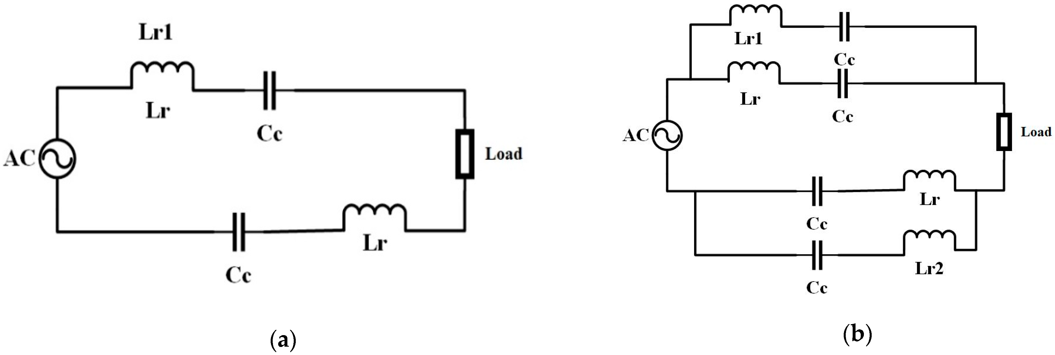
In our proposed method, frequency splitting is utilized to form multi-resonance through the series–series compensation network shown in Figure 2. The 8-plate multi-resonant coupling structure is the modified version of the 4-plate coupling. The 8-plate multi-resonant coupling structure is designed by adding a resonant inductor in series with a capacitive coupling pair. The resultant series LC is parallelly connected to the regular 4-plate coupling structure shown in Figure 2. These new compensation inductors with capacitive coupling pairs are designed to form two additional resonant points along with a resonant point formed by regular 4-plate coupling with a series–series compensation network.

2.1.2. Class-E2 with a 8-Plate Multi-Resonant Coupling Structure

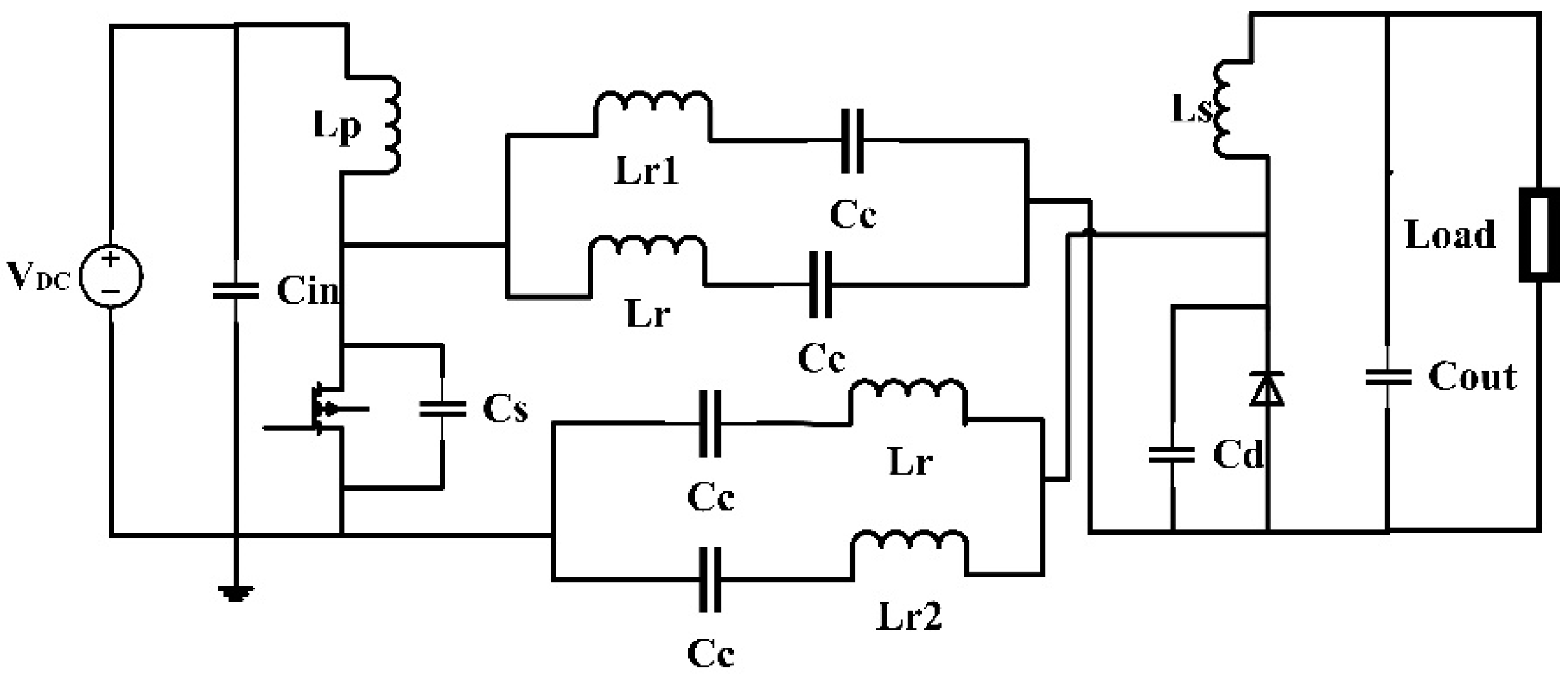
The class-E resonant converter is also known as a high-frequency power amplifier. Compared with other class amplifiers, a class-E converter is a popular single switch topology applied for CPT [30]. Class-E2 as shown in Figure 3 is utilized for this work. It is the combination of a class-E inverter and class-E rectifier. The advantages of a class-E converter include a single active switch with zero-voltage-switching (ZVS), its applicability for high frequencies, and that a series inductor forms resonance with the coupling plates as a series–series compensation network. A class-E inverter circuit is sensitive to parameter variation [29]. For the applied input voltage, the power transfer from the transmitter to the receiver is dependent on the resonant inductor and coupling capacitance. To maintain ZVS for parameter variation such as coupling capacitance or load, ref. [30] uses a control strategy by selecting a proper shunt capacitor. Some papers [21,31] also focused on maintaining ZVS without a control strategy by designing the appropriate impedance matching network. This paper follows the same approach of designing the proper impedance matching network and a shunt capacitor to achieve ZVS for the parameter variations.
The class-E2 converter is a simple circuit with fewer components. In addition to the shunt capacitor (CS) and the switch, the class-E inverter consists of a choke inductor (LP) on the input side to minimize the current ripple. Similarly, the class-E rectifier consists of a secondary inductor and output capacitor as a low-pass filter. Even the class-E rectifier can attain ZVS through a shunt capacitor (Cd) connected in parallel with the diode. The 8-plate multi-resonant coupling structure is applied to the class-E2 power converter shown in Figure 3. Lr is the regular resonant inductors and Lr1 and Lr2 are the additional resonant inductors for multi-resonance. The resonant inductors Lr1 and Lr2 are included to operate as compensation inductors for low coupling capacitance due to misalignments. The order of resonant inductor values for the 8-plate multi-resonant coupling structure is chosen as Lr2 > Lr1 > Lr to compensate for low coupling capacitance due to misalignments. Using the designed parameters, the 8-plate multi-resonant CPT system without misalignment achieves resonance at two branches. For a 0–15% misalignment, the additional inductors can compensate by achieving resonance in one of the new branches based on the coupling capacitance. The reactive power at the coupling section is minimized through the parallel connection of series LC branches. Because of this, the proposed design can increase the power transfer for a wider range of operating frequencies compared with the regular 4-plate coupling structure.

2.2. Impedance Analysis of the 8-Plate Multi-Resonant Coupling Structure

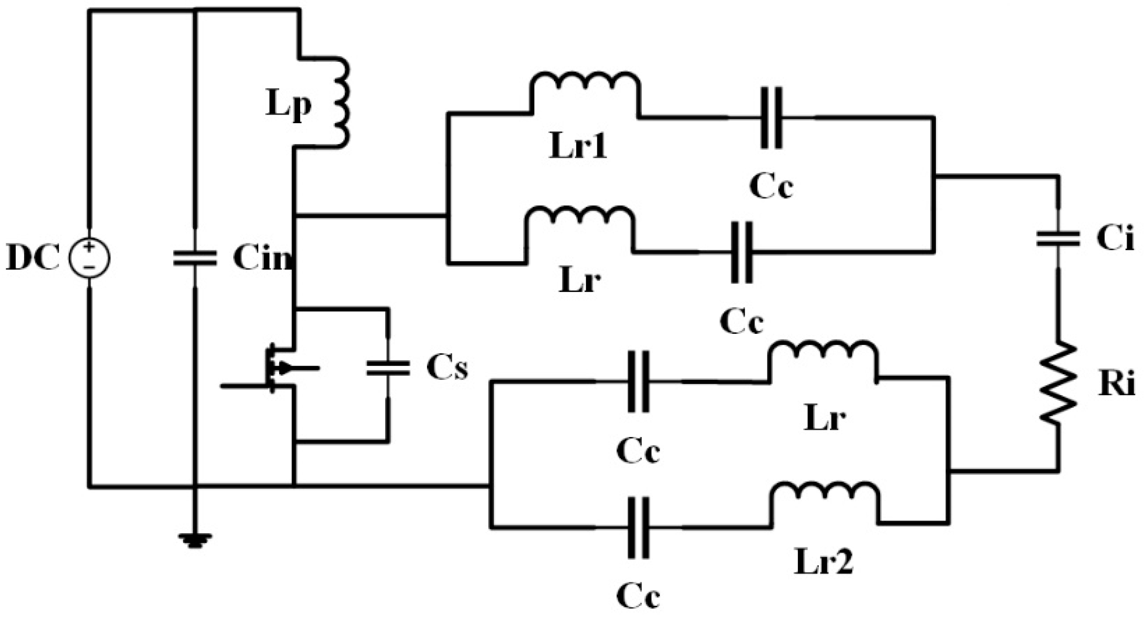
The authors of [18] used the equivalent rectifier model for the impedance analysis of the class-E2-based CPT system. A similar method is applied to determine the impedance curves for the class-E2 converter for both the regular 4-plate coupling and 8-plate multi-resonant coupling structure. Figure 4 shows the equivalent circuit of the class-E2-based 8-plate multi-resonant coupling. To compare 4-plate and 8-plate coupling, the resonant impedance equations for 8-plate multi-resonant coupling were derived to realize the power flow from primary to secondary with respect to the frequency.
Z r = j ( X L r X C c )
Z r 1 = j ( X L r 1 X C c )
Z r 2 = j ( X L r 2 X C c )
Z r e c = R i j X C i
where X L r 1 = ω L r 1 ,   X L r = ω L r ,   X L r 2 = ω L r 2 ,   X C c = ω C c , X C i = ω C i , and ω = 2 π f . Ci and Ri are calculated by using Equations (5)–(7), i.e., (4.7), (4.27), and (4.20) from [32] for the duty cycle D = 0.5.
= a t a n [ 1 C o s ( 2 π D ) 2 π ( 1 D ) + S i n ( 2 π D ) ]
C i C d = π [ π ( 1 D ) + S i n ( 2 π D ) 1 4 C o s ( 2 ) S i n ( 4 π D ) 1 2 S i n ( 2 ) S i n ( 2 π D ) 2 2 π ( 1 D ) S i n ( ) S i n ( 2 π D )   ]
R i R L = 2 S i n ( ) 2
Substituting Equations (1)–(4), resultant equation of the resonant impedance of the 8-plate multi-resonant class-E2-based CPT system with respect to the transmitting side is
Z r e s = R i + j { Z r 1 Z r Z r 1 + Z r + Z r 2 Z r Z r 2 + Z r X C i }  
| Z r e s | = R i 2 + ( Z r 1 Z r Z r 1 + Z r + Z r 2 Z r Z r 2 + Z r X C i ) 2
It is impractical to maintain a constant output for misalignments in the WPT system [26], but the impact can be minimized. This work adopts a method that does not require controllers but uses multi-resonant paths to reduce the drop in output voltage for misalignments. The misalignment drops the value of the coupling capacitance, and the additional resonant inductors must compensate for the low coupling capacitance. The value of the additional resonant inductors (Lr1, Lr2) must now be greater than that of the base resonant inductor (Lr) to handle the misalignments. To illustrate the design procedure, three different sets of inductors were selected as shown in Table 1. For each case in Table 1, a set of different Lr1 and Lr2 are used to implement the impedance variation of the 8-plate multi-resonant coupling structure with respect to the frequency. The values for Lr1 and Lr2 were picked to keep the resonance for a 10% misalignment of the coupling capacitor close to the original resonance frequency. Case (a) is for three resonant inductors with a minimal difference of 1 μH and 3 μH in reference to Lr, and the difference increases progressively from case (a) to case (c) as shown in Table 1.
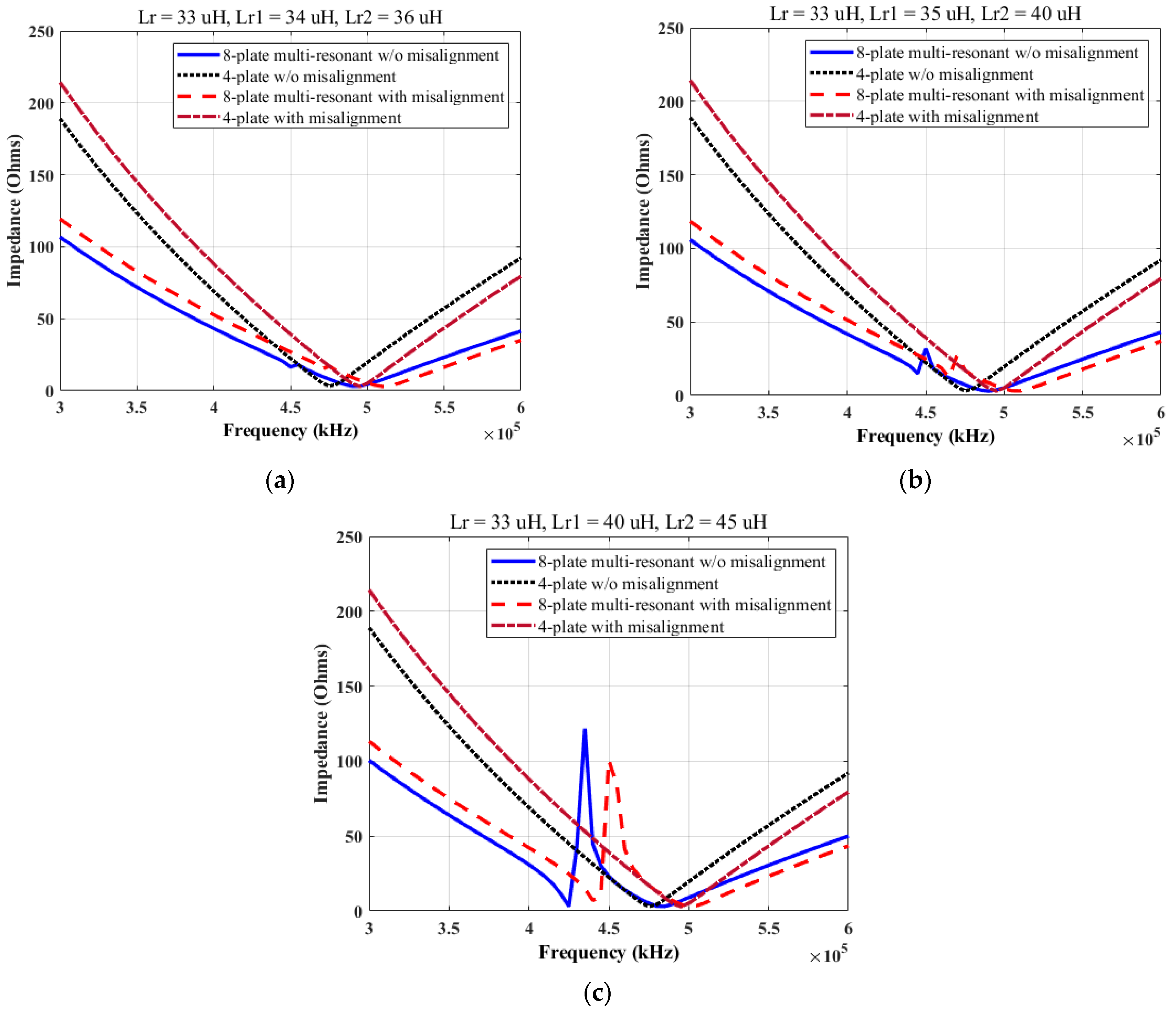
Figure 5 shows the resonant impedance (Equation (9)) plots of 4-plate coupling with a series–series compensation network and the 8-plate multi-resonant coupling structure with and without misalignments for three different cases. The impedance plots demonstrate the design procedure of the 8-plate multi-resonant coupling. For the 4-plate coupling structure, due to series resonance, the impedance is minimal only at the resonant point (which is also the operating frequency), i.e., 470 kHz, whereas the 8-plate multi-resonant coupling structure widens the resonant frequency band based on additional resonant inductor values and provides a better performance for misalignments.
Figure 5a shows the impedance for three resonant inductors with a minimal difference. The impedance plots exhibit smoother curves of the 8-plate coupling for both with and without misalignment for this case. However, the width of the resonant frequency band is small compared with that of case b. Comparing cases a through c, the impedance peak within the resonance frequency band increases with the increase in inductance gap between Lr and Lr1/Lr2 resonant inductor values. As the additional resonant points are far from the original resonant frequency, case c generates a high impedance peak between the additional and original resonant points which is not desirable. In our illustration, case b is the optimum of the three cases as it exhibits a wider resonant frequency band and a minimal impedance peak within the band. For this design, the selection of the additional resonant inductors has a key role in generating a smooth resonant impedance curve for misalignments. The design of Lr1 and Lr2 must provide a wider resonant frequency band with minimal impedance peaks to maintain the output voltage for misalignments.
While designing the class-E2-based CPT system, the operating frequency will be the resonant frequency. Therefore, the operating frequency of the class-E2-based CPT system is 470 kHz for 4-plate and 490 for 8-plate coupling. The concept is to keep the operating frequency constant for misalignment such that additional controller setup is avoided. The performance of both the 4-plate and 8-plate multi-resonant coupling circuit is evaluated for misalignments. For 4-plate coupling, the resonant point shifts to 495 kHz from the original resonant point for a 10% misalignment. The shift in the resonant point increases the resonant impedance at the operating frequency for 4-plate coupling. It affects the power transfer and results in the lowering of the output voltage. For the same misalignment, due to the wider resonance frequency band, the proposed 8-plate multi-resonant coupling resonant impedance is lower at its respective operating frequencies compared with the 4-plate coupling. The 8-plate multi-resonant coupling provides better power transfer with and without misalignments compared to the 4-plate CPT. Additionally, through the proposed coupling design, the impedance away from the resonance point (i.e., at 350 kHz or 600 kHz) is almost half of the impedance of a regular 4-plate with an SS compensation network. The following section presents the results of simulation and hardware tests.

3. Results and Discussions

The coupling setup for the drone charging is shown in Figure 6. The charging pad consists of four transmitting plates. They are placed to match the sequence of drone legs as shown in Figure 6. The receiving plates are attached to the drone legs. Here, the drone is projected to land on the charging pads using the reference points of the charging station to form coupling plate pairs.
The coupling is formed when the drone lands on the charging station. A high coupling capacitance is achieved with a low transmission range. The coupling pairs are positioned far from each other, which eliminates the cross-coupling and self-coupling capacitance. The equivalent model of the coupling plates will be the ideal capacitor. This setup forms a series LC network at each resonant branch. The experimental setup of the 8-plate multi-resonant class-E2 converter is shown in Figure 7. For the 100 W tests, SiC MOSFET (SCT3160KLGC11) is utilized because of low switching and conduction losses for the class-E inverter circuit. The hardware tests are performed for different operating frequencies with an input of 20 V as the input impedance varies with respect to the operating frequency, resulting in the variation of input power. Using the formulas from [21], the parameters of the circuit are presented in Table 2. The maximum output power of 20.8 W is generated at the frequency of 470 kHz using the class-E2 8-plate multi-resonant coupling structure.
Since the design was for a 10% misalignment, the quantitative experimental results presented here are for the 10% misalignment case. Some qualitative observations are also provided for higher misalignments. Figure 8a,b displays the test results of the 4-plate and 8-plate multi-resonant coupling without and with the 10% misalignment. The coupling capacitance of the PZT plates with a 5 cm diameter and 1.5 mm thickness was calculated to be 3.7 nF. For misalignment, the coupling capacitance was found to be 3.45 nF. The output voltage of the 4-plate coupling circuit is shown in Figure 8a, from which we can conclude that the 4-plate has a narrow resonant frequency band {460–465 kHz}. The class-E2 power converter with 4-plate coupling has a single peak that varies with respect to the resonance at the coupling section. The MPPT occurs when the operating frequency is equal to the resonant frequency of the coupling branch. The impedance away from the resonant frequency increases significantly, which results in low power transfer. One of the approaches to handle the misalignment is by increasing the width of the resonant frequency band. Decreasing the quality factor can widen the resonant frequency band, but the circuit with a low-quality factor will decrease the efficiency.
The output voltage at the operating frequency of 460 kHz for the 4-plate coupling without misalignment is noted as 6.15 V. At the same operating frequency, the output voltage with the 10% misalignment is noted as 3.92 V. For the 4-plate coupling circuit, the output voltage drops by 37% for the 10% misalignment. On the other side, using 8-plate coupling, the output voltage at the operating frequency is noted as 7.05 V, whereas for the 10% misalignment it is noted as 5.5 V. A 22% voltage drop is noticed due to the 10% misalignment using the 8-plate multi-resonant coupling. The proposed method minimizes the impact of the misalignment by 15% compared with the 4-plate coupling. Additionally, the 8-plate output voltage is double that of the 4-plate at an operating frequency far from the resonant frequency, meaning it provides better performance for larger misalignments compared with the 4-plate coupling.
Figure 9 shows the waveform plots without and with the 10% misalignment from the hardware tests. From the plots, it can be seen that the ZVS is maintained for ideal cases, i.e., when there is not a misalignment. As class-E is sensitive to parameter variation, the ZVS condition is lost for misalignments at the same operating frequency. The design of the optimal secondary section, such as the selection of the secondary inductor and load to achieve the ZVS for misalignment, can be the future work of the proposed coupling.
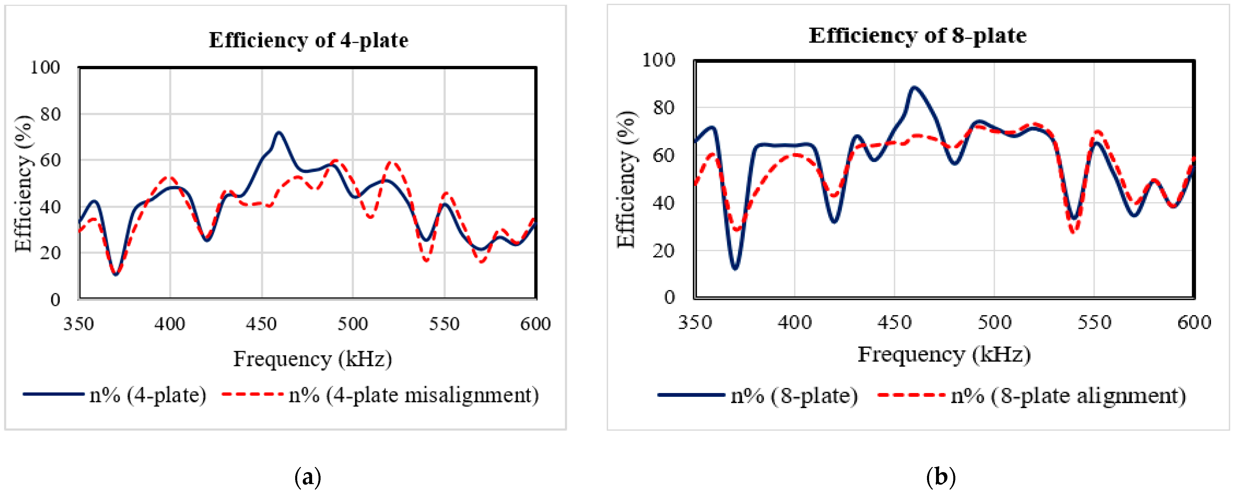
Figure 10 displays the power efficiency of 4-plate and 8-plate multi-resonant CPT with and without misalignment. At their respective resonant frequencies, the efficiency is expected to be high for both 4-plate and 8-plate multi-resonant coupling. The efficiency of the 4-plate class-E2 CPT system is measured as 70.2%, whereas for the 8-plate multi-resonant coupling it is noted as 88.5% at 460 kHz, which is 2.2% higher than the separated circular coupling plates used for drone charging [5]. The proposed multi-resonant coupling enhances efficiency by 18.3% using the same components of the 4-plate coupling class-E2 setup. Additionally, the efficiency of the 8-plate coupling remains over 60% for most of the frequencies within a range of {350–600 kHz}. The parallel connection of the series LC resonant network minimizes the impedance of the coupling section, which improves the power transfer.

4. Conclusions

Misalignment decreases the coupling capacitance and adds reactive power to the circuit, which reduces the output voltage and the overall efficiency. The proposed novel 8-plate multi-resonant coupling overcomes the effect of misalignment without the need for control schemes. The proposed design is suitable for a 100 Ah drone battery charging circuit. The coupling is achieved when the drone lands on the charging pad. With a short transmission range, the CPT system is operated in the hundreds of kHz frequency range for the coupling capacitance in nano-farads. The proposed coupling design enhances the efficiency to 88.5% using the class-E2-based CPT for a 20.8 W hardware test. Through the multi-resonance, the resonance frequency band of the class-E2-based CPT system is increased from 5 kHz to 30 kHz. Because of the parallel connection of series–series compensation, the reactance of the coupling section is minimized over a broad range of frequencies, which minimizes the loss of performance due to misalignments. The proposed 8-plate multi-resonant coupling improves the output voltage of the class-E2-based CPT system by 15% compared with the regular 4-plate coupling for 10% misalignments. Even at an ideal coupling, i.e., without misalignment, the 8-plate multi-resonance coupling’s efficiency is 18.3% higher than that if the regular 4-plate coupling. For large misalignments, the 8-plate multi-resonant coupling circuits have a 40% better performance than that of the 4-plate coupling.

Author Contributions

Conceptualization, Y.B.; methodology, Y.B. and S.K.D.; software, Y.B.; validation, Y.B.; formal analysis, Y.B.; investigation, Y.B.; resources, S.K.D.; writing—original draft preparation, Y.B.; writing—review and editing, S.K.D.; supervision, S.K.D. All authors have read and agreed to the published version of the manuscript.

Funding

This work was supported by the U.S. Department of Energy, Office of Fusion Energy Sciences Award DE-SC0020183.

Acknowledgments

This work was partially supported by the Department of Electrical and Computer Engineering, Old Dominion University, Norfolk.

Conflicts of Interest

The authors declare no conflict of interest.

References

  1. da Silva, G.G.; Petry, C.A. Capacitive Wireless Power Transfer System Applied to Low-Power Mobile Device Charging. Int. J. Electr. Energy 2015, 3, 230–234. [Google Scholar] [CrossRef] [Green Version]
  2. Regensburger, B.; Afridi, K.K. Challenges and Solutions to Passive Rectification in Multi-MHz Frequency Capacitive Wireless Power Transfer Systems for Electric Vehicle Charging. In Proceedings of the 2020 IEEE Energy Conversion Congress and Exposition, Detroit, MI, USA, 11–15 October 2020; pp. 5482–5486. [Google Scholar] [CrossRef]
  3. Yang, L.; Zhang, Y.; Li, X.; Jian, J.; Wang, Z.; Huang, J.; Ma, L.; Tong, X. Analysis and Design of Four-Plate Capacitive Wireless Power Transfer System for Undersea Applications. CES Trans. Electr. Mach. Syst. 2021, 5, 202–211. [Google Scholar] [CrossRef]
  4. Tamura, M.; Murai, K.; Matsumoto, M. Design of Disposable Film-Type Capacitive Wireless Charging for Implantable Medical Devices. In Proceedings of the 2021 IEEE MTT-S International Microwave Symposium (IMS), Atlanta, GA, USA, 7–25 June 2021; pp. 58–61. [Google Scholar] [CrossRef]
  5. Park, C.; Park, J.; Shin, Y.; Kim, J.; Huh, S.; Park, S.; Ahn, S. Separated Circular Capacitive Coupler for Reducing Cross-Coupling Capacitance in Drone Wireless Power Transfer System. IEEE Trans. Microw. Theory Tech. 2020, 68, 3978–3985. [Google Scholar] [CrossRef]
  6. Allamehzadeh, H. Wireless Power Transfer (WPT) Fundamentals with Resonant Frequency-Dependent Parameters, Energy Transfer Efficiency, and Green Technology Applications. In Proceedings of the 2021 IEEE 48th Photovoltaic Specialists Conference (PVSC), Fort Lauderdale, FL, USA, 20–25 June 2021; pp. 0036–0040. [Google Scholar] [CrossRef]
  7. Minnaert, B.; Costanzo, A.; Monti, G.; Mongiardo, M. Capacitive Wireless Power Transfer with Multiple Transmitters: Efficiency Optimization. Energies 2020, 13, 3482. [Google Scholar] [CrossRef]
  8. Lu, F.; Zhang, H.; Mi, C. A Review on the Recent Development of Capacitive Wireless Power Transfer Technology. Energies 2017, 10, 1752. [Google Scholar] [CrossRef] [Green Version]
  9. Regensburger, B.; Kumar, A.; Sinha, S.; Doubleday, K.; Pervaiz, S.; Popovic, Z.; Afridi, K. High-Performance Large Air-Gap Capacitive Wireless Power Transfer System for Electric Vehicle Charging. In Proceedings of the 2017 IEEE Transportation Electrification Conference and Expo (ITEC), Chicago, IL, USA, 22–24 June 2017; pp. 638–643. [Google Scholar]
  10. Vincent, D.; Huynh, P.S.; Patnaik, L.; Williamson, S.S. Prospects of Capacitive Wireless Power Transfer (C-WPT) for Unmanned Aerial Vehicles. In Proceedings of the 2018 IEEE PELS Workshop on Emerging Technologies: Wireless Power Transfer (WoW), Montreal, QC, Canada, 3–7 June 2018; pp. 1–5. [Google Scholar]
  11. Zhang, H.; Lu, F.; Hofmann, H.; Liu, W.; Mi, C.C. A Four-Plate Compact Capacitive Coupler Design and LCL-Compensated Topology for Capacitive Power Transfer in Electric Vehicle Charging Application. IEEE Trans. Power Electron. 2016, 31, 8541–8551. [Google Scholar]
  12. Bezawada, Y.; Fu, R.; Zhang, Y. Impacts of Coupling Plates on Single-Switch Capacitive-Coupled WPT Systems. In Proceedings of the 2019 IEEE PELS Workshop on Emerging Technologies: Wireless Power Transfer (WoW), London, UK, 18–21 June 2019; pp. 330–334. [Google Scholar]
  13. Zhang, H.; Lu, F.; Hofmann, H.; Liu, W.; Mi, C.C. Six-Plate Capacitive Coupler to Reduce Electric Field Emission in Large Air-Gap Capacitive Power Transfer. IEEE Trans. Power Electron. 2017, 33, 665–675. [Google Scholar] [CrossRef]
  14. Ahmad, S.; Hattori, R.; Muharam, A. Generalized Circuit Model of Shielded Capacitive Power Transfer. Energies 2021, 14, 2826. [Google Scholar] [CrossRef]
  15. Luo, B.; Long, T.; Guo, L.; Dai, R.; Mai, R.; He, Z. Analysis and Design of Inductive and Capacitive Hybrid Wireless Power Transfer System for Railway Application. IEEE Trans. Ind. Appl. 2020, 56, 3034–3042. [Google Scholar] [CrossRef]
  16. Vincent, D.; Huynh, P.S.; Azeez, N.A.; Patnaik, L.; Williamson, S.S. Evolution of Hybrid Inductive and Capacitive AC Links for Wireless EV Charging—A Comparative Overview. IEEE Trans. Transp. Electrif. 2019, 5, 1060–1077. [Google Scholar] [CrossRef]
  17. Vincent, D.; Sang, P.H.; Williamson, S.S. Feasibility Study of Hybrid Inductive and Capacitive Wireless Power Transfer for Future Transportation. In Proceedings of the 2017 IEEE Transportation Electrification Conference and Expo (ITEC), Chicago, IL, USA, 22–24 June 2017; pp. 229–233. [Google Scholar] [CrossRef]
  18. Sinha, S.; Kumar, A.; Regensburger, B.; Afridi, K.K. Active Variable Reactance Rectifier—A New Approach to Compensating for Coupling Variations in Wireless Power Transfer Systems. IEEE J. Emerg. Sel. Top. Power Electron. 2019, 8, 2022–2040. [Google Scholar] [CrossRef]
  19. Cipriani, E.; Colantonia, P.; Giannini, F.; Giofre, R. The Switchws Mode Power Amplifiers. Advanced Microwave and Millimeter Wave Technologies; Mukherjee, M., Ed.; IntechOpen: London, UK, 2010; pp. 359–388. [Google Scholar]
  20. Roshani, S.; Roshani, S. Design of a High Efficiency Class-F Power Amplifier with Large Signal and Small Signal Measurements. Measurement 2020, 149, 106991. [Google Scholar] [CrossRef]
  21. Bezawada, Y.; Zhang, Y. A Case Study: Influence of Circuit Impedance on the Performance of Class-E2 Resonant Power Converter for Capacitive Wireless Power Transfer. Electronics 2021, 10, 1461. [Google Scholar] [CrossRef]
  22. Lecluyse, C.; Minnaert, B.; Kleemann, M. A Review of the Current State of Technology of Capacitive Wireless Power Transfer. Energies 2021, 14, 5862. [Google Scholar] [CrossRef]
  23. Li, H.; Wang, K.; Fang, J.; Tang, Y. Pulse Density Modulated ZVS Full-Bridge Converters for Wireless Power Transfer Systems. IEEE Trans. Power Electron. 2018, 34, 369–377. [Google Scholar] [CrossRef]
  24. Kumar, A.; Sinha, S.; Sepahvand, A.; Afridi, K.K. Improved Design Optimization for High-Efficiency Matching Networks. IEEE Trans. Power Electron. 2017, 33, 37–50. [Google Scholar] [CrossRef]
  25. Niu, W.; Gu, W.; Chu, J.; Shen, A. Frequency Splitting Patterns in Wireless Power Relay Transfer. IET Circuits Devices Syst. 2014, 8, 561–567. [Google Scholar] [CrossRef]
  26. Suarez, C.; Kalmes, M.; Suffeleers, J.; Martinez, W. Frequency Splitting in an LCLC Capacitive Wireless Power Transfer System for Electric Vehicle Charging. In Proceedings of the IECON 2020 The 46th Annual Conference of the IEEE Industrial Electronics Society, Singapore, 18–21 October 2020; pp. 3622–3627. [Google Scholar] [CrossRef]
  27. Huang, R.; Zhang, B.; Qiu, D.; Zhang, Y. Frequency Splitting Phenomena of Magnetic Resonant Coupling Wireless Power Transfer. IEEE Trans. Magn. 2014, 50, 1–4. [Google Scholar] [CrossRef]
  28. Zhang, Y.; Zhao, Z. Frequency Splitting Analysis of Two-Coil Resonant Wireless Power Transfer. IEEE Antennas Wirel. Propag. Lett. 2014, 13, 400–402. [Google Scholar] [CrossRef]
  29. Jennings, R.; Bezawada, Y.; Zhang, Y.; Fu, R. Sensitivity of Conversion Efficiency with Variable Load Assignment in Class-E Resonant Inverter and Its Derivatives. In Proceedings of the 2016 IEEE International Telecommunications Energy Conference (INTELEC), Austin, TX, USA, 23–27 October 2016; pp. 1–7. [Google Scholar] [CrossRef]
  30. Chokkalingam, B.; Padmanaban, S.; Leonowicz, Z.M. Class E Power Amplifier Design and Optimization for the Capacitive Coupled Wireless Power Transfer System in Biomedical Implants. Energies 2017, 10, 1409. [Google Scholar] [CrossRef]
  31. Lu, K.; Nguang, S.K.; Ji, S.; Wei, L. Design of Auto Frequency Tuning Capacitive Power Transfer System Based on Class-E 2 dc/dc Converter. IET Power Electron. 2017, 10, 1588–1595. [Google Scholar] [CrossRef]
  32. Kazimierczuk, M.K.; Czarkowski, D. Resonant Power Converters; John and Wiley and Sons: Hoboken, NJ, USA, 2012. [Google Scholar]
Figure 1. Fundamental block diagram of CPT.
Electronics 11 00635 g001
Figure 2. Framework of 8-plate multi-resonant coupling structure: (a) 4-plate coupling equivalent circuit and (b) 8-plate multi-resonant coupling equivalent circuit.
Electronics 11 00635 g002
Figure 3. Class-E2 with 8-plate multi-resonant coupling structure.
Electronics 11 00635 g003
Figure 4. Equivalent rectifier circuit of class-E2 converter with 8-plate multi-resonant coupling.
Electronics 11 00635 g004
Figure 5. Resonant impedance plots of 4-plate and 8-plate multi-resonant coupling with and without misalignment for three cases; (ac) correspond to the inductor values in Table 1.
Electronics 11 00635 g005
Figure 6. Drone charging using 8-plate coupling plates.
Electronics 11 00635 g006
Figure 7. Experimental set of 8-plate capacitive coupling.
Electronics 11 00635 g007
Figure 8. Output voltage of class-E2 CPT with and without misalignments: (a) 4-plate coupling and (b) 8-plate coupling.
Electronics 11 00635 g008
Figure 9. Waveform of the class-E2 with 8-plate multi-resonant coupling (blue: gate signal, purple: voltage across MOSFET, orange: voltage across diode) (a) without misalignment and (b) with 10% misalignment.
Electronics 11 00635 g009
Figure 10. Efficiency of class-E2 CPT with and without misalignments: (a) 4-plate coupling and (b) 8-plate coupling.
Electronics 11 00635 g010
Table 1. Cases based on additional resonant inductor values.
CaseLrLr1Lr2
a33 μH34 μH36 μH
b33 μH35 μH40 μH
c33 μH40 μH45 μH
Table 2. Parameters of class-E2 power converter with 4-plate and 8-plate multi-resonant coupling.
ComponentsParametersValues for 4-PlateValues for 8-Plate
DC link/input capacitorCin100 nF100 nF
Choke/primary inductorLp33 μH33 μH
Shunt capacitor at MOSFETCs1 nF1 nF
Coupling capacitorCc3.75 nF3.75 nF
Resonant inductorsLr33 μH33 μH
Lr137 μH
Lr240 μH
Shunt capacitor at diodeCd1 nF1 nF
Secondary inductorLs33 μH33 μH
Output capacitorCout1 μF1 μF
Load resistorRL2.4 Ω2.4 Ω
Publisher’s Note: MDPI stays neutral with regard to jurisdictional claims in published maps and institutional affiliations.