Article

Control Design of Observer-Based Virtual Soft Boundary for a Power-Assist System with Limited Operating Range

Department of Mechatronics Engineering, National Kaohsiung University of Science and Technology, No.1 University Rd., Yanchao District, Kaohsiung City 824, Taiwan
*
Author to whom correspondence should be addressed.
Electronics 2022, 11(5), 690; https://doi.org/10.3390/electronics11050690
Submission received: 12 January 2022 / Revised: 18 February 2022 / Accepted: 19 February 2022 / Published: 23 February 2022

Abstract

:
Control design of power-assist systems has been widely applied to human-robot interactive systems such as wearable exoskeleton systems, of which the range of motion limitation of human joints in the power-assist systems is essential. This paper presents a virtual soft boundary design for a human-robot cooperation system with a limited operating range. The proposed virtual soft boundary is realized by impedance control and integrated into the power-assist robot arm system; meanwhile, power-assist robot arm systems are typical human-in-the-loop systems, and the control of the power-assist system in performing in accordance with a human’s perception is a significant issue. Therefore, a model-based disturbance observer with a pseudo-derivative feedback feedforward (PDFF) compensator is designed to effectively estimate the human’s torque for an appropriate motor torque command. Experimental results show that the proposed control method can estimate the human torque exerted on the robot arm system to achieve a power-assist system, and the virtual soft boundary can be realized by the impedance control and integrated into the power-assist robot arm system.

1. Introduction

The concept of a power-assist system, which was first discussed by the Cornell Aeronautical Laboratory in 1968 [1], was a concept with the purpose of assisting people with disabilities by using a wearable exoskeleton. The evolution of robotics research over the last 50 years has also pointed out the significance of power-assist technology developed in robotics research [2]. Hence, the control design of power-assist techniques is indeed essential for the human-robot interactive system. Moreover, service robots incorporating physical human-robot interaction (pHRI) have recently become an important trend outside industrial applications for addressing the new needs and markets in daily human life [3,4,5,6]. The general ability of service robots makes it necessary to work closely with humans; thus, researching control techniques for pHRI should be central in the development of service robots [7]. Control design of power-assist devices is regarded as an essential technique for dealing with pHRI because of its compliance design, and it has recently been investigated in several service robots, such as power-assisted wheelchairs [5], cycle ergometers for stroke rehabilitation [8], walking assisted robots [9], ankle rehabilitation robotic devices [10], and so on.
Control design of a power-assist system can be defined as assistance to motions for the purpose of enhancing user mobility or reducing user effort. Power assistance supported by servo motors is not intended to entirely replace user effort. The power-assist system is operated in accordance with a user’s perception; hence, the servo motor should be sensitive to the force the user exerts on the system [11,12]. Force sensors are a straightforward solution for obtaining user force information. However, directly detecting user force by sensors is not practical for implementation due to the problems of installation and wiring. To overcome the sensing issue, several studies on sensing indirect force have been developed, such as a strain gauge device equipped with a Wheatstone bridge, which has been integrated into a robotic rehabilitation exoskeleton for a user’s tremor force assessment [13]. Additionally, an angle sensor, a linear potentiometer, and touch sensors were designed to monitor the torque of the user’s below-knee exoskeleton [14]. Furthermore, a load cell collocated with a linear encoder has been employed to develop a torque-controllable actuator for the knee assistance device [15]. However, the structure of those indirect sensing devices still involves issues of installation and wiring.
Therefore, using model-based observers instead of force sensors has been recommended for estimating the human propel efforts of power-assist systems [5,6,8,16], in which only the excitation signal (i.e., the current input of a servo motor) and a measurable feedback signal (i.e., the motor position output information) are necessary for the presented observer. Further, the structure of the model-based observer primarily consists of five elements: excitation signal of the control system, sensor output, mathematical model of the control plant, a mathematical model of the sensor, and an observer compensator. Although the performance of an observer compensator with a pseudo-derivative feedback (PDF) controller has been verified in [6,8,16], the pseudo-derivative feedback feedforward (PDFF) controller is proposed to improve the transient response of the estimated external force in this study.
Moreover, various power assist human-robot systems, especially in wearable exoskeletons, are performed in accordance with the user’s joint motion. Therefore, it is essential to achieve the compliance characteristics in the power-assist system [17]. For example, an admittance control of powered exoskeletons based on joint torque estimation was presented to render a trajectory-free compliance control law [18]; then, to ensure recursive feasibility and constraint compliance, the predictive control of a tube-based model was employed to regulate a knee joint with functional electrical stimulation [19]. Further, the full-active electro-hydrostatic powered ankle prosthesis was implemented to provide initiative compliance while assisting push-off at the end of the stance phase [20]. However, the range of motion (ROM) of human joints is generally operated with limitations while the joint is flexing or extending. The demand of the virtual soft boundary must be realized in the power-assist human-robot systems to avoid the risk of extreme flexing or extending. Hence, the virtual soft boundary realized by the impedance control is integrated with the disturbance estimation to achieve the compliant operation of the power assist human-robot system, constrained by the ROM of the human joints.
The remainder of this paper is organized as follows: Section 2 discusses the dynamics model of a one-link robot arm and the design of the model-based disturbance observer. Then, the range planning of ROM, control design of the power-assisted mode, and impedance control are proposed to deal with the limited operating range in Section 3. Further, the experiment results and discussion are presented in Section 4. A conclusion is then provided in Section 5.

2. Dynamics Modeling and Disturbance Estimation

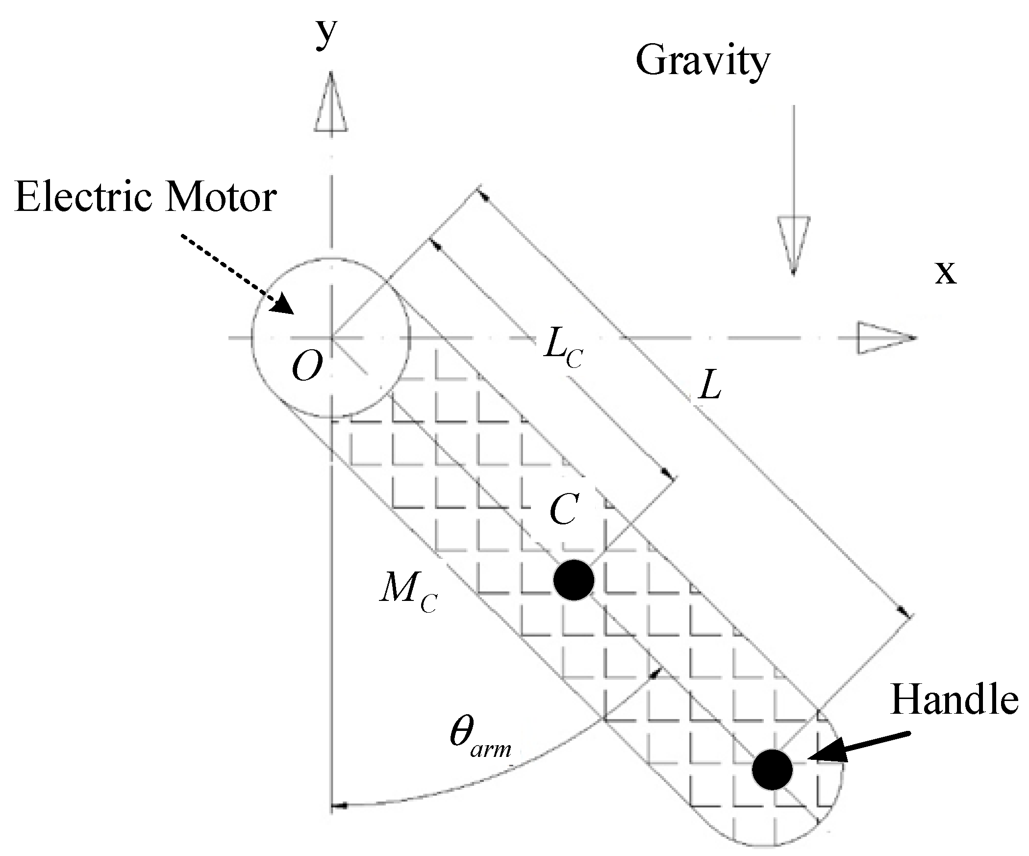
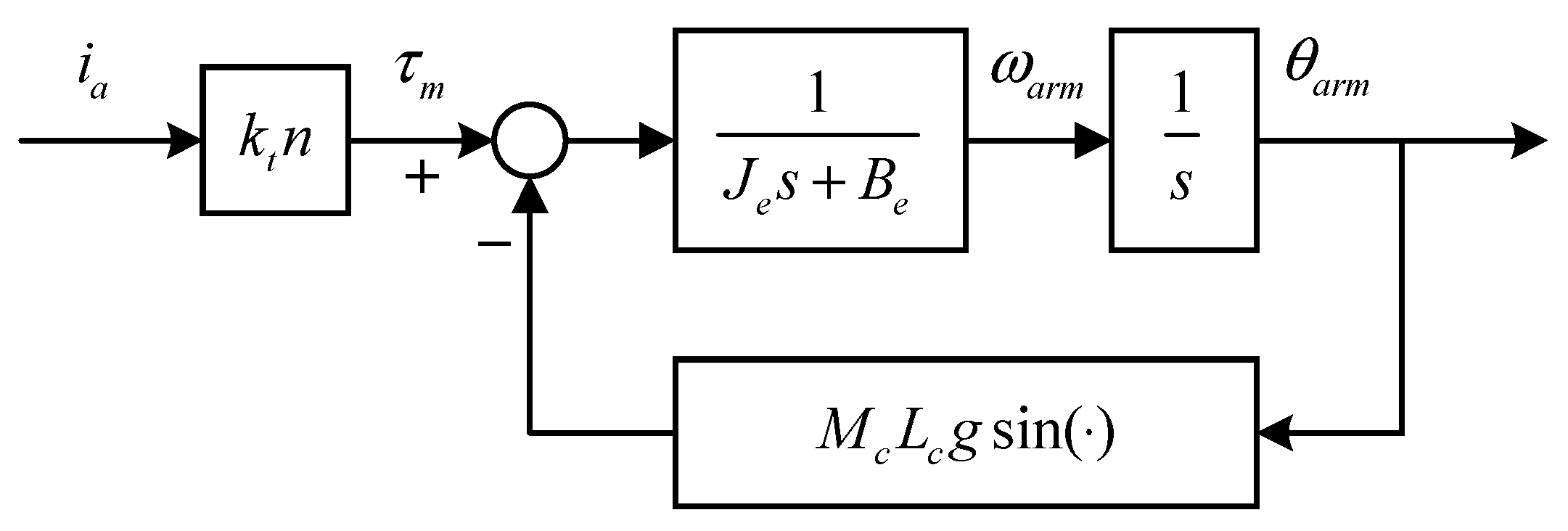
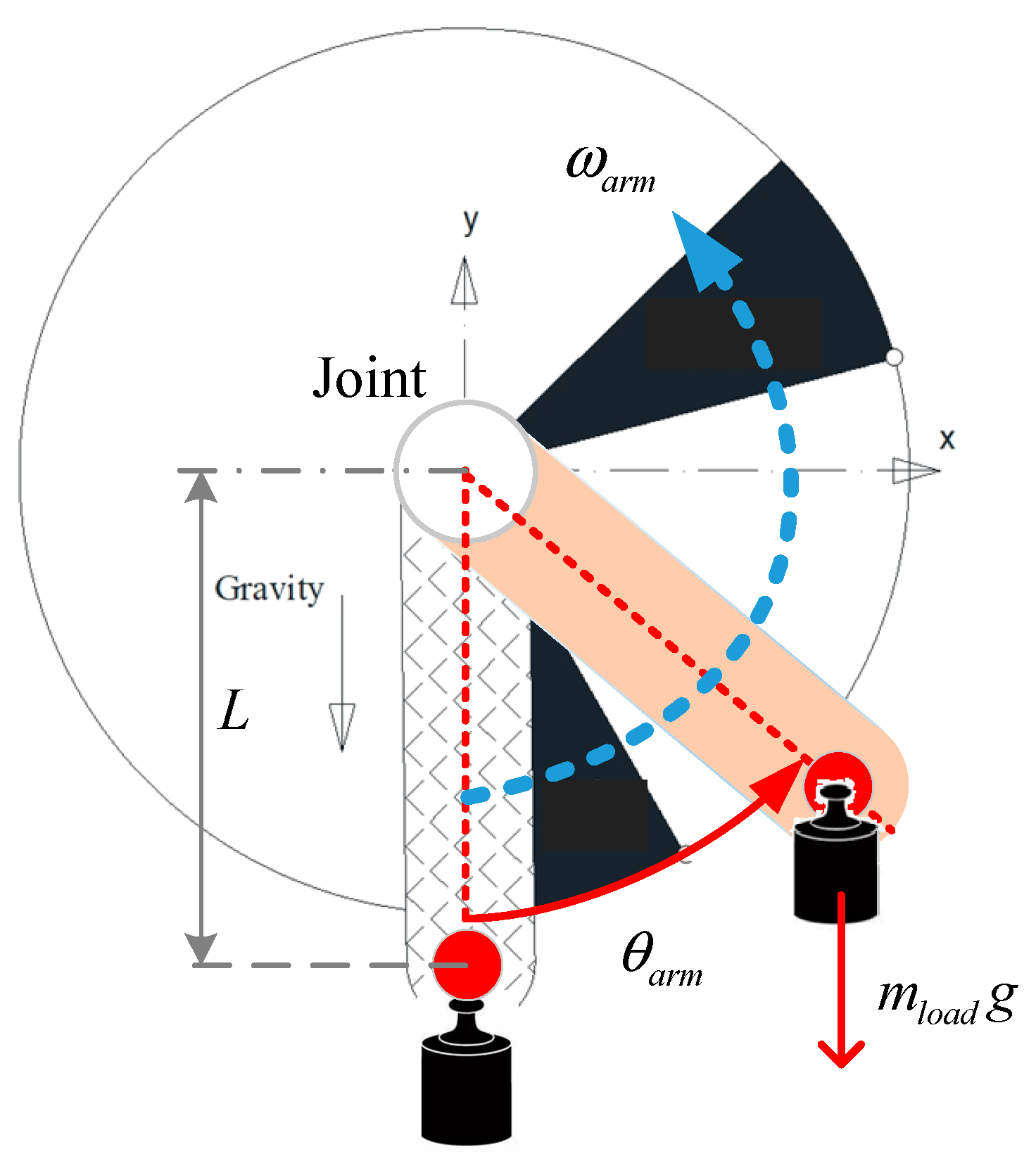
2.1. System Dynamic Modeling

In order to validate the assistant control approach, this study applied the proposed control system to a one-link robot arm driven by an electric motor. The demonstration set-up with a single degree-of-freedom is illustrated in Figure 1, where the end of the robot arm can be forced by human force. Then, an electric motor can be used to amplify the operator’s force for the driven loading. Further, the dynamic model of the controlled system was conducted to investigate the power-assist system driven by the human force.
Based on Figure 1, Figure 2 shows a schematic view of the one-link robot arm model, where C presents the mass center of the robot arm, L denotes the length of the original point O to the handle of the robot arm, and L c indicates the length of O C ¯ . Additionally, θ a r m presents the angular position of the robot arm. Then, the total kinetic and potential energy function can be employed to derive the dynamic equations of the system in Figure 2. Here, the kinetic and potential energy function is considered by the Lagrangian function L given by
L = 1 2 M c v c 2 + 1 2 I c θ ˙ a r m 2 + M c L c g cos ( θ a r m )
where M c denotes the total mass of the one-link robot arm, v c ( = L c θ ˙ a r m ) indicates the tangent velocity of the center of mass of the robot arm, and I c represents the inertia of the one-link robot arm with respect to the vertical axis through C.
Furthermore, to include the dissipated energy caused by viscous friction, the additional term of the dissipation function D = B e θ ˙ a r m 2 / 2 is obtained, where B e presents the equivalent viscous coefficient of the system. Thus, the dynamic equation of the one-link robot arm is governed by:
d d t ( L θ ˙ a r m ) L θ a r m + D θ ˙ a r m = τ m
where τ m indicates the electric motor torque output. Let τ m = k t n i a , where k t is the torque constant of the driving motor, n is the gear reduction ratio, and i a denotes the input current of the driving motor. Solving the Lagrange equation will yield the dynamics model of the one-link robot arm:
τ m = J e θ ¨ + B e θ ˙ + M c L c g sin ( θ a r m )
where J e ( = M c L c 2 + I c ) is the equivalent inertia of the one-link robot arm. Then, the block diagram of the one-link robot arm model is described in Figure 3. In order to obtain the parameter of the system in Figure 3, the mathematical model is calculated by spectrum analysis of the frequency response of the proposed system. Therefore, the parameters of J e = 0.2379 kg m2 and B e = 0.5545 Nm/(rad/s) can be obtained. Additionally, the friction model recognized by [21] is depicted in Figure 4. The static and Coulomb friction is described in Table 1 and applied to compensate for the friction in the control system.

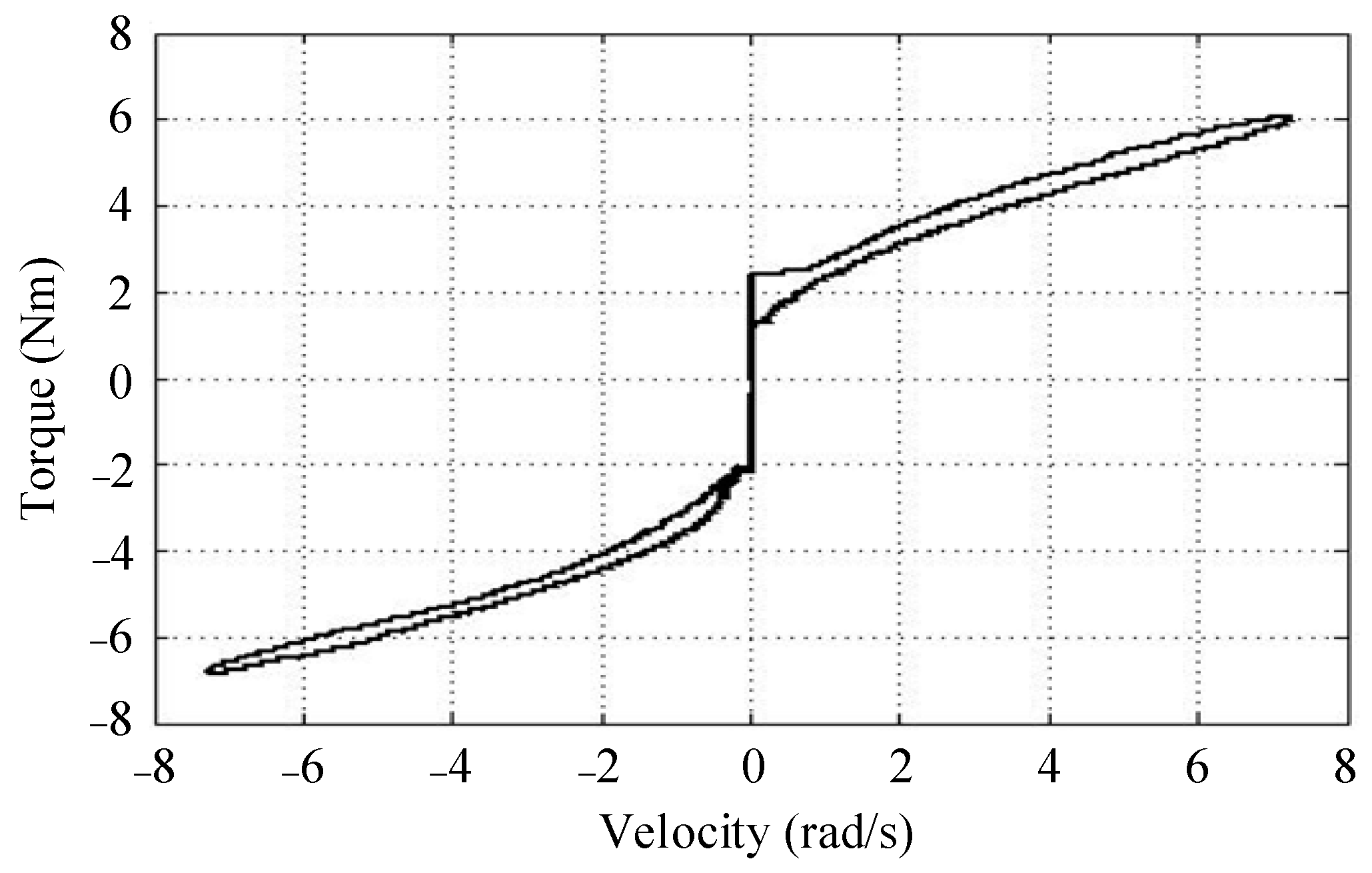
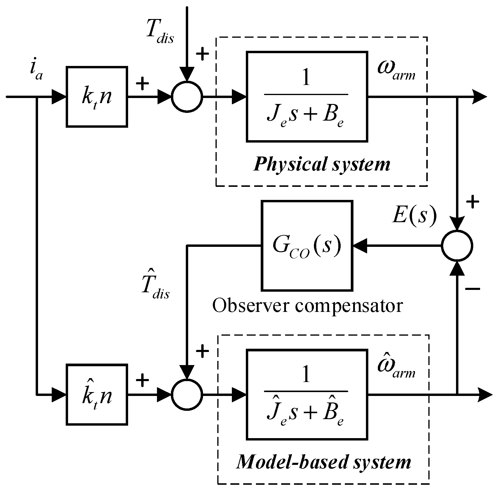
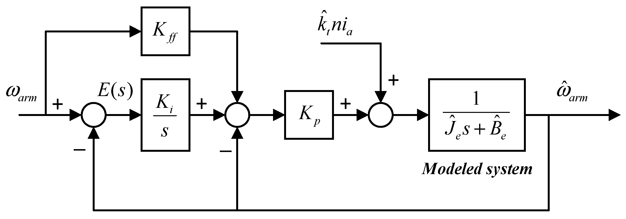
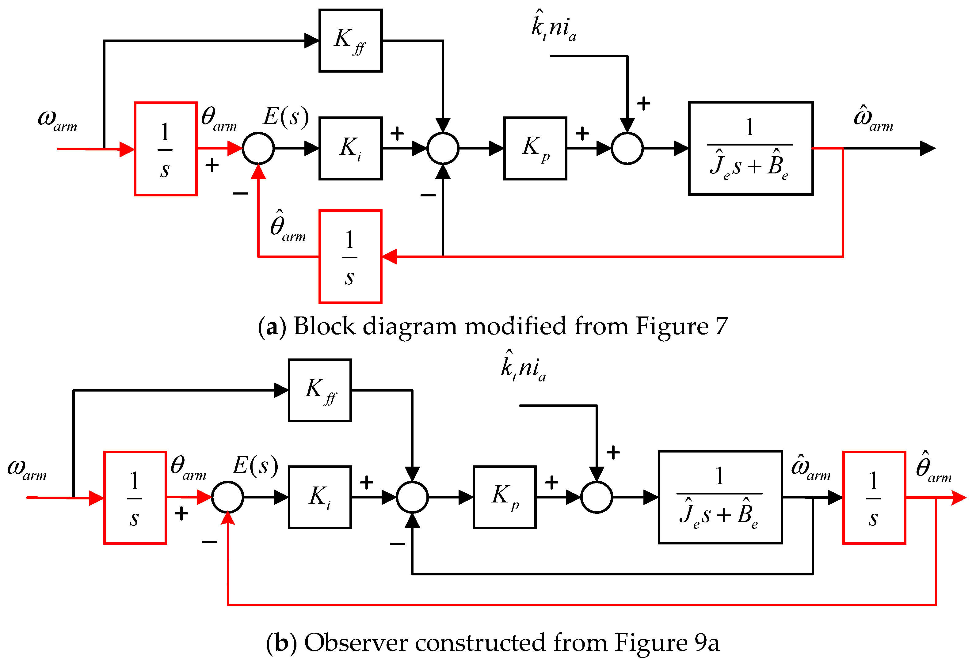
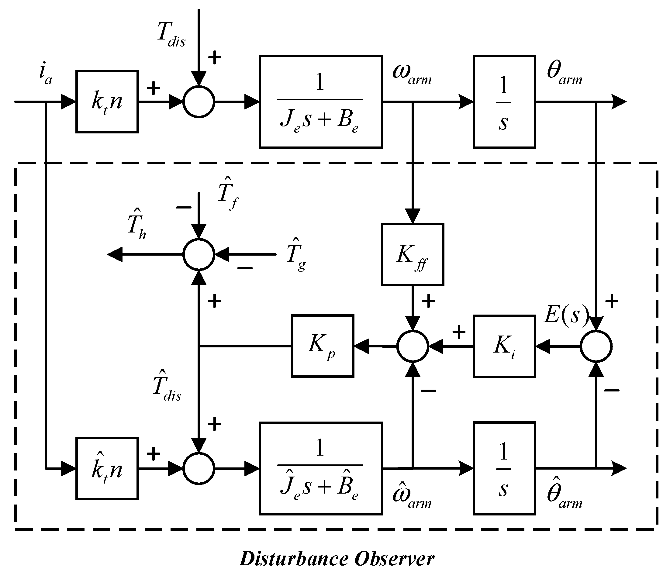
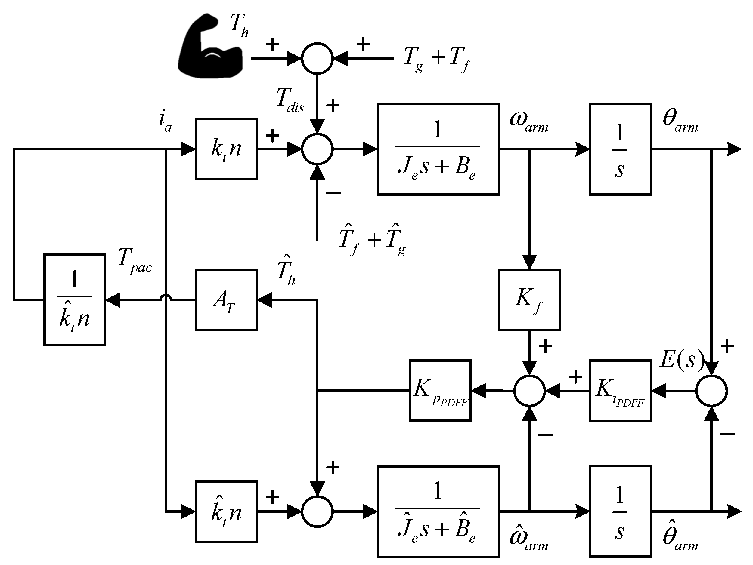
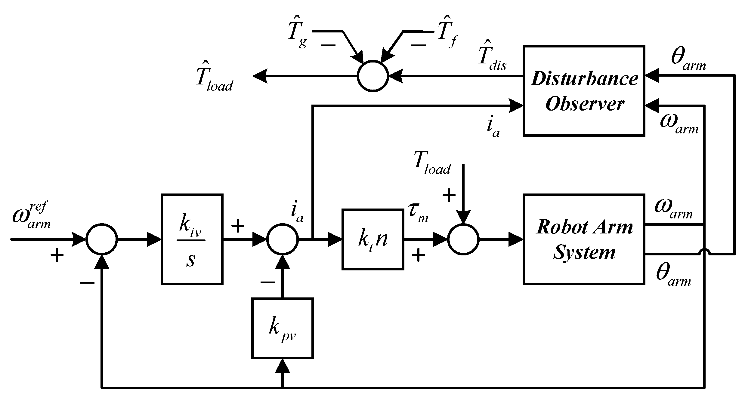
2.2. External Disturbance Estimation

According to previous analyses, the one-link robot arm system can be modeled as in Figure 3, where Je and Be indicate the equivalent inertia and viscous coefficient of the system. Then, kt and ia are the torque constant and current input of an electric motor. Further, ωarm and θarm present the angular velocity and position information of the robot arm. Suppose that Tdis denotes the external disturbance of the system, which consists of the external human propel torque Th, the friction Tf, and the gravity effect Tg. Thus, Tdis can be expressed as:
T d i s = T h + T f + T g
where T g = M c L c g sin ( θ a r m ) . Since the parameter of the friction model T f can be obtained from Figure 4 and Table 1, the input of the propelled external human torque in the system can be given by:
T h = T d i s T g T f
Hence, the human propelled input can be estimated by T d i s . In this study, the model-based observer applied for estimating the human’s propel effort was developed by [22]. In general, the model-based observer primarily consists of five elements: plant excitation signal, real sensor output, an estimated model of the control plant, a model of the sensor, and an observer compensator. Assume that the angular velocity of the robot arm system can be measured. Then, the one-link robot arm system combined with the model-based observer can be presented as in Figure 5, where i a indicates the system excitation signal, ω a r m is the real sensor output, 1 / ( J ^ e s + B ^ e ) presents the estimated model of the control plant, and G c o ( s ) denotes the observer compensator. Moreover, the model of the sensor is assumed to be equal to one. Since converging the observed error, E = ω a r m ω ^ a r m is one of the primary issues in the model-based observer and properly designing the observer compensator G c o ( s ) is essential.
From Figure 5, an appropriate design of the compensator G c o ( s ) is similar to regulating a compensator in a speed feedback control system, which can be found in Figure 6. Although the performance of the compensator G c o ( s ) designed by a PDF controller [6,8,23] has been verified, a PDFF controller is proposed to improve the transient response of the external disturbance estimation in this study. The observer compensator formed by the PDFF controller is illustrated in Figure 7, where K p and K i are the proportional and integral gain of the observer compensator, respectively. Furthermore, K f f is an additional feedforward gain. It can be seen that the PDFF controller constitutes a generalized PDF controller K f f = 0. Suppose that G v ( s ) is the transfer function from ω a r m to ω ^ a r m . Thus, we have
ω ^ a r m ω a r m = G v ( s ) = K f f K p s + K i K p J ^ e s 2 + ( K p + B ^ e ) s + K i K p
To compare the PDF controller in [8] and the PDFF controllers in Figure 7, (6) can be represented by a second-order low-pass filter with the desired natural frequency ω n O B and damping ratio ς O B , such as:
G v ( s ) = K f f K p s / J ^ e + K i K p / J ^ e s 2 + ( B ^ e + K p ) s / J ^ e + K i K p / J ^ e = K f f ( 2 ζ O B ω n O B B ^ e / J ^ e ) s + ω n O B 2 s 2 + 2 ζ O B ω n O B s + ω n O B 2
where
{ ω n O B 2 = K i K p / J ^ e 2 ζ O B ω n O B = ( B ^ e + K p ) / J ^ e   and   { K p = 2 ζ O B ω n O B J ^ e B ^ e K i = ω n O B 2 J ^ e / K p
From (7) and according to the definition of bandwidth in the second-order system, we have:
| K f f ( 2 ζ O B ω n O B B ^ e / J ^ e ) ( j ω b w O B ) + ω n O B 2 ( j ω b w O B ) 2 + 2 ζ O B ω n O B ( j ω b w O B ) + ω n O B 2 | = 1 2
Assume that B ^ e can be initially compensated; thus the natural frequency ω n O B in the observer is obtained by the relationship of (9) [24].
Suppose that the low-speed movement of the human robot-arm system is chosen to avoid damage. The bandwidth and damping ratio in the second-order system of (7) is designed by ω b w O B = 30 rad/s ( 4.77 Hz) and ζ O B =1 (critically damped). Therefore, the designed parameters of the observer are listed in Table 2. Further, the performance of the step response in the observer design is depicted in Figure 8, where the solid line presents the result of the observer while K f f = 0, and the dash-dotted line indicates the performance of the observer with the feedforward gain tuned by K f f = 0.25. Since the PDFF controller is equivalent to a generalized PDF controller of K f f = 0, the transient response of PDFF 25 is better than that of the PDF (PDFF 0). Further, the rising time is improved from 0.072 s. (PDFF0) to 0.053 s. (PDFF25). Hence, in this study, the PDFF controller K f f = 0.25 is integrated into the model-based observer design for estimating external disturbance.
However, the actual sensor output of the one-link robot arm system is θ a r m (measured by the incremental optical encoder). Further, the PDFF controller can be implemented as in Figure 9a. To use the measured position information for speed control and torque observer design, the structure of Figure 9a can be redrawn by the equivalent block diagram illustrated in Figure 9b. Considering practical implementation, the proposed disturbance observer integrated with the structure of Figure 9b is shown in Figure 10, in which only the measured motor current (input) i a and position (output) θ a r m are utilized to estimate the external disturbance T d i s . From Figure 10, the transfer function between actual disturbance input T d i s and estimated disturbance T ^ d i s is given by:
T ^ d i s T d i s = ( J ^ e s + B ^ e ) ( J e s + B e ) K f f K p s / J ^ e + K i K p / J ^ e s 2 + ( B ^ e + K p ) / J ^ e s + K i K p / J ^ e = ( J ^ e s + B ^ e ) ( J e s + B e ) G v ( s )
Assuming that the estimated equivalent inertia J ^ e and viscous coefficient B ^ e of the one-link robot arm is approximated to the actual equivalent inertia J e and viscous coefficient B e , (10) can therefore be rewritten as:
T ^ d i s T d i s K f f K p s / J ^ e + K i K p / J ^ e s 2 + ( B ^ e + K p ) / J ^ e s + K i K p / J ^ e = G v ( s )
where the performance of G v ( s ) can be analyzed by (7)–(9) in the previous description. In other words, this indicates that the human propel effort T h can be obtained based on the proposed observer as:
T ^ h = T ^ d i s T ^ g T ^ f
where the performance of the estimated T ^ h can be conducted in the following experimental section.

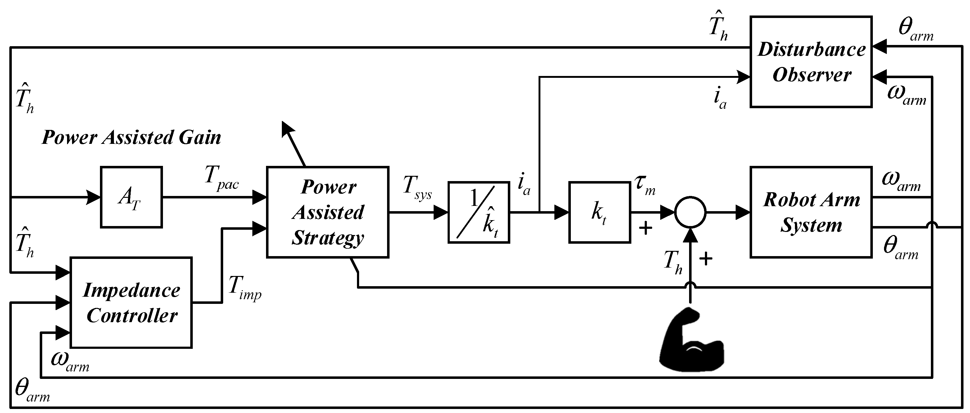
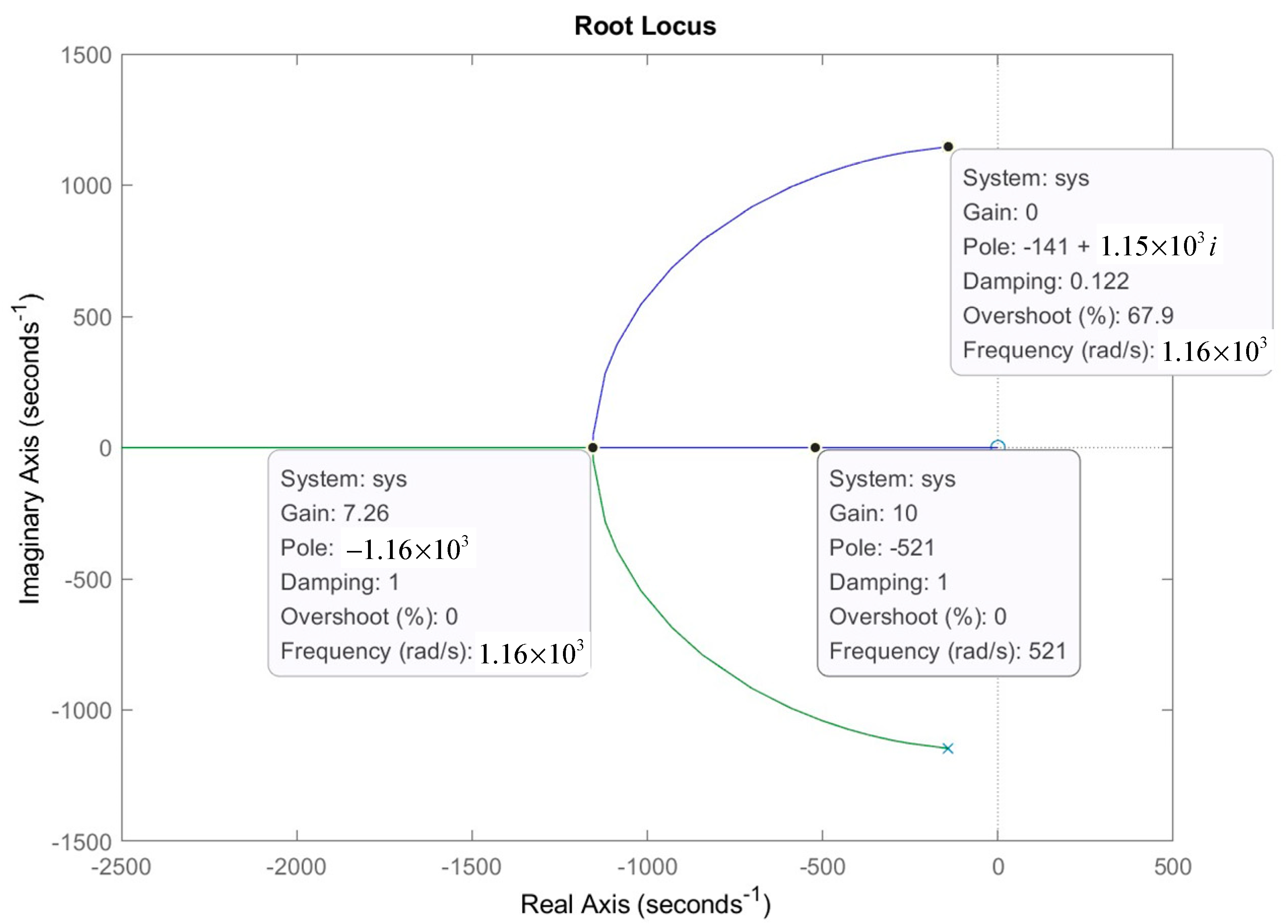
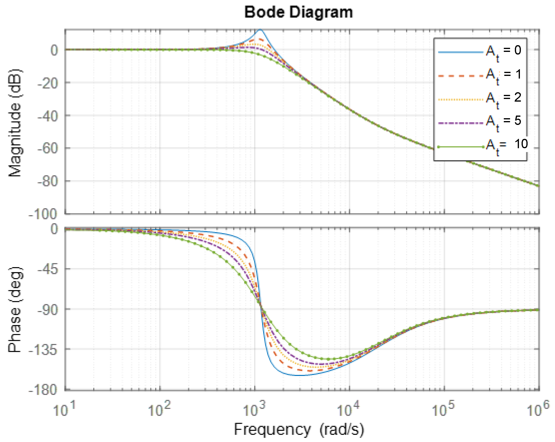
3. Control Design of Power-Assist System with Limited Operating Range

In general, the range of motion (ROM) of human joints is operated with limitations while the joint is flexing or extending. Hence, it is necessary to consider the issue of limited operation in a power-assist system. Figure 11 presents the control strategy of a power-assist system with an operating limitation in the one-link robot arm system, where θ R O M indicates the ROM, θ I M P shows the angle range of the impedance mode, and θ P A C presents the angle range of the power-assisted control mode. According to the control strategy in Figure 11, the torque sensorless power-assist system integrated by the impedance control is proposed in Figure 12, where the robot arm system is mentioned in the previous section. Further, T s y s is the power-assisted control law and can be designed as
T s y s = { T i m p ,   for   0 θ a r m < θ I M P   o r   ( θ I M P + θ P A C ) θ a r m < θ R O M T p a c ,   for   θ I M P θ a r m < ( θ I M P + θ P A C )
where T i m p is the power-assisted command of the impedance mode in the intervals of A and C. Then, T p a c = A T T ^ h indicates the command of the power-assisted mode in the interval of B with the power-assisted ratio A T .
In the intervals of A and C, impedance control is applied to improve the safety of human-robot interaction in the boundary of ROM [25]. Thus, the impedance control scheme can be designed as Figure 13, where the inner-loop is the velocity loop control with the adjustable parameters k i m p 1 and k i m p 2 . The outer-loop dominates the position feedback control with a proportional gain k i m p 3 . Furthermore, the θ a r m * is the desired position command generated by the required impedance model of the inertia J i m p , damping B i m p , and stiffness K i m p .
Moreover, due to the fact that Interval B presents the power-assisted mode, the power-assisted control law T s y s in Interval B can be designed as:
T s y s = T p a c = A T T ^ h
where A T is represented as the power-assisted ratio and T ^ h indicates the estimated human propel input. To verify the stability of the power-assisted mode, the block diagram of the power-assisted mode is illustrated in Figure 14. Thus, the estimated human input T ^ h can be expressed by
T ^ h = K p ( K f f ω a r m + K i E ( s ) ω ^ a r m )
where E ( s ) = θ a r m θ ^ a r m = ( ω a r m ω ^ a r m ) / s . Assuming that the estimated equivalent inertia J ^ e , viscous coefficient B ^ e , and motor torque constant k ^ t of the one-link robot arm are approximated to the actual equivalent inertia J e , viscous coefficient B e and motor torque constant k t , (15) can therefore be rewritten as:
T ^ h = K p K f f s + K p K i J ^ e s 2 + ( B ^ e + K p ) s + K p K i T h + ( K f f 1 ) K p s J ^ e s 2 + ( B ^ e + K p ) s + K p K i T p a c
According to (14) and (16), the transfer function of the estimated human input T ^ h in the power-assisted control mode is conducted by:
T ^ h T h = K P P D F F K f s + K P P D F F K i P D F F J ^ e s 2 + [ B ^ e + K P P D F F + ( K P P D F F K f ) A T ] s + K P P D F F K i P D F F
Meanwhile, the root locus and frequency response of (17) are shown in Figure 15 and Figure 16, respectively. Obviously, the system is stable with the design of the power-assisted ratio A T = 0 ~ 10.

4. Experimental Verification

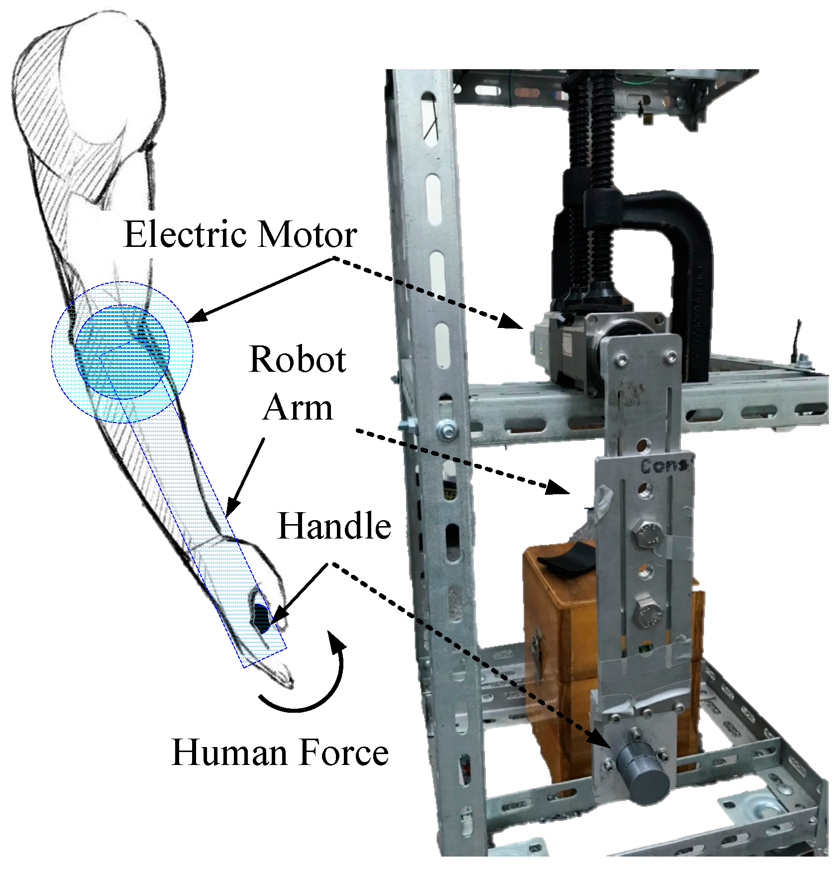
4.1. Experimental System

Figure 17 presents an experimental system of this study, where a DSP-based controller is an intelligent motion control platform with a PowerPC 400 embedded processor. The one-link robot arm is driven by a 400 W electric motor with the resolution 2500 pulses/rev of the encoder and a gear ratio n = 40 of the gearbox. Further, the ADXL335 accelerometer is utilized to measure the position θ a r m of the robot arm. The parameters of the robot arm in Figure 3 are obtained by spectrum analysis of the frequency response of the proposed system, where k ^ t = 1.3/3 Nm/A, J ^ e = 0.2379 kg·m2, and B ^ e = 0.5545 Nm/(rad/s).

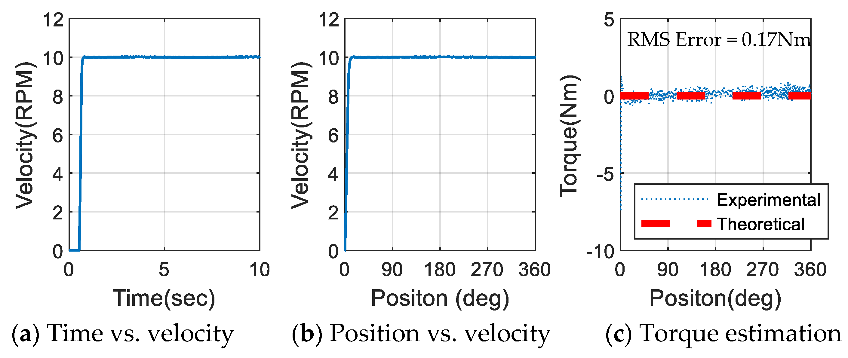
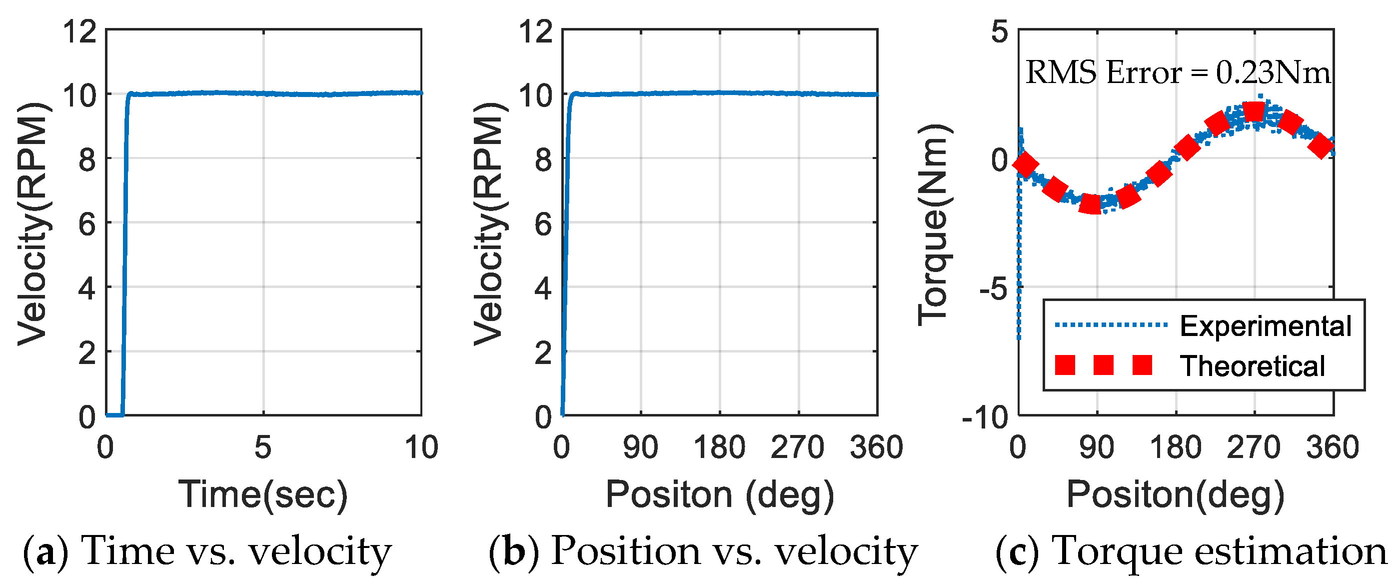
4.2. Verification of Disturbance Estimating

The effectiveness of the proposed disturbance observer is confirmed by experiments with a load weight m l o a d on the end of the robot arm. Thus, the load torque T l o a d can be obtained by:
T l o a d = m l o a d g L sin ( θ a r m )
Then, the experimental progress is that the robot arm makes a circular motion with a fixed angular velocity ω a r m as shown in Figure 18. Further, the estimated load torque of the experimental results is similar to (12) and can be described by:
T ^ l o a d = T ^ d i s T ^ g T ^ f
Subsequently, theoretical and experimental results were compared to examine validity. The load torque following the three cases at ω a r m r e f = 10 RPM with the proposed disturbance observer was conducted by three cases, i.e., case A: m l o a d = 0 kg, case B: m l o a d = 0.5 kg, and case C: m l o a d = 1 kg. Figure 19 shows the velocity control structure utilized to verify the disturbance estimation, where the transfer function from ω a r m r e f to ω a r m is formulated as:
ω a r m ω a r m r e f = k i v k ^ t n / J ^ e s 2 + ( B ^ e + k p v k ^ t n ) s / J ^ e + k i v k ^ t n / J ^ e = ω n 2 s 2 + 2 ζ ω n s + ω n 2
It can be seen from (20), that the controller parameters are related to a standard second-order system. Choosing the natural frequency ω n = 2π × 10 rad/s and the damping ratio ζ = 1, the integral and proportional gains k i v and k p v , respectively, of the velocity control are given by:
{ k i v = ( ω n 2 J ^ e ) / ( k ^ t n ) = 54.18 k p v = ( 2 ζ ω n J ^ e B ^ e ) / ( k ^ t n ) = 1.69
Experimental results corresponding to the three cases are presented in Figure 20, Figure 21 and Figure 22. First, the velocity response is anticipated to be 10 RPM with insignificant variation in each condition. From (19), the estimated load torque should be equal to zero while m l o a d = 0 kg of case A. Thus, the dashed line presents the theoretical value shown in Figure 20c, whereas the dotted line is the load torque estimated by the proposed disturbance observer in case A. Obviously, the dotted line is approximate to the dashed line. Then, the estimated load torques tested by standard weights in case B ( m l o a d = 0.5 kg) and case C ( m l o a d = 1 kg) are shown in Figure 21c and Figure 22c, where the estimated load torque (dotted line) is close to the theoretical results (dashed line). Eventually, the root mean square error is adopted to further evaluate the performance of the proposed torque observer in all three cases, of which all incidences with RMS errors are 0.17 Nm, 0.23 Nm, and 0.25 Nm.

4.3. Realize the Control of the Power-Assist System and Impedance Control

Based on the above examination of torque estimation, the torque sensorless power-assist system based on the observer can be verified with the configuration in Figure 23a, where the extra load attached at the end of the robot is 1 kg. Furthermore, the assistance power is realized by (14) with A T = 0, 1, and 2. Since the experimental configuration is categorized in the power-assisted mode mentioned in Section 2, the results of the power-assisted ratio A T = 0, 1, and 2 are depicted in Figure 24 with the operating range θ R O M = 0 ~ 75 (0~1.31 rad). With A T = 0 (without the assistance power) as shown in Figure 24a, the initial disturbance estimation is around –3.91 Nm, which occurs because of the extra load. To operate the one-link robot in the range of θ R O M , the maximum human torque is 6.94 Nm. Then, the maximum human torque is reduced to 5.38 Nm due to the increased power-assisted ratio A T = 1 as shown in Figure 24b. Eventually, the maximum human torque is decreased to 4.51 Nm at A T = 2 . Therefore, the human effort can be alleviated with the proposed torque sensorless power-assist system.
Further, the soft boundary based on the impedance control can be verified by the experimental setup in Figure 23b. The user pulls the handle attached to the end of the robot arm and the control system provides the impedance torque T i m p gently against the user’s effort. Hence, the haptic effect of the soft boundary between the human and machine can be achieved. The parameters of the three cases for the impedance model are listed in Table 3, and the results of the impedance model are shown in Figure 25, where the dashed line indicates the variation of the robot arm position and the solid line presents the human torque T ^ h .
Since stiffness κ is the extent to which an object resists deformation in response to an applied force, the definition of κ is expressed as κ = f o r c e   o n   t h e   b o d y   ( T ^ h ) /   d i s p l a c e m e n t in this study. In other words, the complementary perception is flexibility, compliance, or softness. The softer an object is, the less stiff it is. The result of case A is shown in Figure 25a; the human torque is smoothly increased according to the position information and impedance parameters B i m p and K i m p , and the maximum T ^ h is around 19.2 Nm with the maximum position variation. Further, the stiffness κ gradually approaches 100 (Nm/rad). Then, K i m p in case B is two times that of case A, in other words, the stiffness in case B is slightly larger than in case A. Hence, the maximum T ^ h is about 23.2 Nm of the soft boundary in the maximum position variation in Figure 25b, and the stiffness κ gradually approaches 200 (Nm/rad). Finally, B i m p in case C is four times that of case A; to put it another way, it is difficult for the user to facilitate pulling the robot arm, and the result is presented in Figure 25c. Meanwhile, the stiffness κ is gradually approaching 100 (Nm/rad). To indicate the stiffness variation for presenting the characteristics of the soft boundary, the results are illustrated in Figure 26 during the position displacement close to the ROM limitation.

5. Conclusion and Future Work

This paper proposes a model-based disturbance observer based on a PDFF type compensator to enhance the transient response of torque estimation. The transient response of PDFF 25 is better than that of the PDF typed compensator since the rising time is improved by about 26.4% from 0.072 s (PDF compensator) to 0.053 s (PDFF25 compensator). Then, the PDFF compensator was integrated into the model-based observer for estimating the external disturbance. The performance of torque estimation is verified in the experimental section. Evidently, the estimated load torque is approximately equal to the theoretical results, and the human effort is available to be alleviated with a proposed torque sensorless power-assist robot arm system based on torque estimation.
Further, due to the ROM limitation of the human joints, the risk of extreme flexing or extending in the power-assist robot arm system should be avoided. Thus, the virtual soft boundary was realized by the impedance control and integrated into the power-assist system. The compliance characteristic is comprehended in the boundary of the ROM according to the desired impedance model. Hence, the experimental results not only show the capability of the torque estimation and soft boundary but also ensure the stability of the power-assist robot arm system. Future work will focus on the experiment with a more powerful electric motor and heavy loads since the power-assist robot arm system may be operated for hard work in the future.

Author Contributions

P.-W.H. contributed to the research concept, methodology, data collection and data validation. W.-S.Y. provided the advice on the research. T.-M.K. contributed to the software development, experimental planning and execution, and data analysis. P.-W.H. wrote the manuscript draft. W.-S.Y. reviewed and revised the manuscript. All authors have read and agreed to the published version of the manuscript.

Funding

This research was funded by the Ministry of Science and Technology of Taiwan, under grant number MOST 110-2221-E-992-088.

Conflicts of Interest

The authors declare no conflict of interest.

References

  1. Miller, J.S. The Myotron—A Servo-Controlled Exoskeleton for the Measurement of Muscular Kinetics; Final Technical Report of Cornell Aeronautical Lab Inc Buffalo: New York, NY, USA, 1968. [Google Scholar]
  2. Garcia, E.; Jimenez, M.A.; de Santos, P.G.; Armada, M. The Evolution of Robotics Research—From Industrial Robotics to Field and Service Robotics. IEEE Robot. Autom. Mag. 2007, 14, 90–103. [Google Scholar] [CrossRef]
  3. Kim, Y.; Yoon, W.C. Generating Task-Oriented Interactions of Service Robots. IEEE Trans. Syst. Man Cybern. Syst. 2014, 44, 9. [Google Scholar] [CrossRef]
  4. Hao, M.; Cao, W.H.; Wu, M.; Liu, Z.T.; Li, S.H. An Initiative Service Method Based on Fuzzy Analytical Hierarchy Process and Context Interntion Inference for Drinking Service Robot. IEEE Trans. Cogn. Dev. Syst. 2019, 11, 221–233. [Google Scholar]
  5. Tsai, M.C.; Hsueh, P.W. Force Sensorless Control of Power Assisted Wheelchair Based on Motion Coordinate Transformation. Mechatronics 2013, 23, 1014–1024. [Google Scholar] [CrossRef]
  6. Hsueh, P.W.; Tsai, M.C. Reactive Torque Monitoring and Cycling Speed Control of a Belt-Driven Cycle Ergometer. Control. Eng. Pract. 2013, 21, 1564–1576. [Google Scholar] [CrossRef]
  7. Hu, Y.; Benallegue, M.; Venture, G.; Yoshida, E. Interact with Me: An Exploratory Study on Interaction Factors for Active Physical Human-Robot Interaction. IEEE Robot. Autom. Lett. 2020, 5, 6764–6771. [Google Scholar] [CrossRef]
  8. Hsueh, P.W.; Tsai, M.C.; Chen, C.-L. Stimulation Interval Evaluation for Lower-Limb Cycling Movement Based on Torque Observer. Asia J. Control. 2017, 20, 1–13. [Google Scholar] [CrossRef]
  9. Wang, W.; Chen, J.; Ji, Y.; Jin, W.; Liu, J.; Zhang, J. Evaluation of Lower Leg Muscle Activities During Human Walking Assisted by an Ankle Exoskeleton. IEEE Trans. Ind. Inform. 2020, 16, 7168–7176. [Google Scholar] [CrossRef]
  10. Ren, Y.; Wu, Y.N.; Yang, C.Y.; Xu, T.; Harvey, R.L.; Zhang, L.Q. Developing a Wearable Ankle Rehabilitation Robotic Device for in-Bed Acute Stroke Rehabilitation. IEEE Trans. Neural Syst. Rehabil. Eng. 2017, 25, 589–596. [Google Scholar] [CrossRef]
  11. Oh, S.; Hata, N.; Hori, Y. Proposal of Human-Friendly Motion Control. In Proceedings of the 30th Annual Conference of the IEEE Industrial Electronics Society, Busan, Korea, 2–6 November 2004; pp. 436–441. [Google Scholar]
  12. Tanako, N.; Iwama, T.; Kumagai, S.; Takanishi, A.; Lim, H. New Collistion Force Suppression Mechanism and Based Control of Human-Friendly Robot. In Proceedings of the 18th International Conference on Control, Automation and Systems, Pyeongchang, Korea, 17–18 October 2018. [Google Scholar]
  13. Rocon, E.; Belda-Lois, J.M.; Ruiz, A.F.; Manto, M.; Moreno, J.C.; Pons, J.L. Design and Validation of a Rehabilitation Robotic Exoskeleton for Tremor Assessment and Suppression. IEEE Trans. Neural Syst. Rehabil. Eng. 2007, 15, 367–378. [Google Scholar] [CrossRef] [Green Version]
  14. Zhu, J.; Wang, Q.; Huang, Y.; Wang, L. Adding Compliant Joints and Segmented Foot to Bio-Inspired Below-Knee Exoskeleton. In Proceedings of the IEEE International Conference on Robotics and Automation, Shanghai, China, 9–13 May 2011. [Google Scholar]
  15. Shepherd, M.K.; Rouse, E.J. Design and Characterization of a Torque-Controllable Actuator for Knee Assistance During Sit-to-Stand. In Proceedings of the 38th Annual International Conference of the IEEE Engineering in Medicine and Biology Society, Orlando, FL, USA, 16–20 August 2016; pp. 2228–2231. [Google Scholar]
  16. Hsueh, P.W.; Chen, J.C.; Yao, W.S.; Tsai, M.C.; Syu, W.C. Luenberger Observer-Based Impedance Control of Linear Servo Motor for a Desired Haptic System. In Proceedings of the International Automatic Control Conference, Nantou Country, Taiwan, 2–4 December 2013. [Google Scholar]
  17. Pervez, A.; Ryu, J. Safe Physical Human Robot Interaction-Past, Present and Future. J. Mech. Sci. Technol. 2008, 22, 469–483. [Google Scholar] [CrossRef]
  18. Liang, C.; Hsian, T. Admittance Control of Powered Exoskeletons Based on Joint Torque Estimation. IEEE Access 2020, 8, 94404–94414. [Google Scholar] [CrossRef]
  19. Bao, X.; Sheng, Z.; Dicianno, B.E.; Sharma, N. A Tube-Based Model Predictive Control Method to Regulate a Knee Joint with Functional Electrical Stimulation and Electric Motor Assist. IEEE Trans. Control. Syst. Technol. 2020, 29, 2180–2191. [Google Scholar] [CrossRef]
  20. Liu, H.; Huang, Q.; Tong, Z. Simulation and Analysis of a Full-Active Electro- Hydrostatic Powered Ankle Prosthesis. In Proceedings of the 19th International Conference on Advanced Robotics, Delo Horizonte, Brasil, 2–6 December 2019. [Google Scholar]
  21. Johnson, C.T.; Lorenz, R.D. Experimental Identification of Friction and its Compensation in Precise, Position Controlled Mechanisms. IEEE Trans. Ind. Appl. 1992, 28, 1392–1398. [Google Scholar] [CrossRef]
  22. Ellis, G. Observers in Control System (A Practical Guide); Academic Press: Cambridge, MA, USA, 2002. [Google Scholar]
  23. Ohm, D.Y. Analysis of PID and PDFF Compensators for Motion Control Systems. In Proceedings of the 1994 IEEE Industry Applications Society Annual Meeting, Denver, CO, USA, 2–6 October 1994. [Google Scholar]
  24. Golnaraghi, F.; Kuo, B.C. Automatic Control Systems 9/e; John Wiley & Sons Inc.: Hoboken, NJ, USA, 2010. [Google Scholar]
  25. Song, P.; Yu, Y.; Zhang, X. Impedance Control of Robots: An Overview. In Proceedings of the 2nd International Conference on Cybernetics, Robotics and Control, Chengdu, China, 21–23 July 2017. [Google Scholar]
Figure 1. Experimental setup of the power-assist system.
Electronics 11 00690 g001
Figure 2. Schematic representation of the one-link robot arm.
Electronics 11 00690 g002
Figure 3. Block diagram of the one-link robot arm model.
Electronics 11 00690 g003
Figure 4. Friction model of the one-link robot arm.
Electronics 11 00690 g004
Figure 5. Model-based observer utilized in the one-link robot arm system.
Electronics 11 00690 g005
Figure 6. Observer utilized in the one-link robot arm system.
Electronics 11 00690 g006
Figure 7. Observer compensator formed by the PDFF controller.
Electronics 11 00690 g007
Figure 8. The step response of the observer design.
Electronics 11 00690 g008
Figure 9. The modification of the observer design.
Electronics 11 00690 g009
Figure 10. Proposed disturbance observer.
Electronics 11 00690 g010
Figure 11. Control strategy of power-assist system with operating limitation.
Electronics 11 00690 g011
Figure 12. Control structure of the torque sensorless power-assist system with impedance controller.
Electronics 11 00690 g012
Figure 13. Structure of the proposed impedance controller.
Electronics 11 00690 g013
Figure 14. Block diagram of the control design of power-assisted mode.
Electronics 11 00690 g014
Figure 15. Root locus of the power-assisted mode with AT.
Electronics 11 00690 g015
Figure 16. Bode plot of power-assisted mode with A T .
Electronics 11 00690 g016
Figure 17. Experimental setup of the one-link robot arm.
Electronics 11 00690 g017
Figure 18. Testing loads at the end of the robot arm.
Electronics 11 00690 g018
Figure 19. Velocity control structure for verifying the disturbance observer.
Electronics 11 00690 g019
Figure 20. Validity of load torque estimation (case A: m l o a d = 0 kg).
Electronics 11 00690 g020
Figure 21. Validity of load torque estimation (case B: = 0.5 kg).
Electronics 11 00690 g021
Figure 22. Validity of load torque estimation (case C: m l o a d = 1 kg).
Electronics 11 00690 g022
Figure 23. Experimental setup of power-assisted and impedance control mode.
Electronics 11 00690 g023
Figure 24. Responses of the power-assist mode with A T = 0, 1, and 2.
Electronics 11 00690 g024
Figure 25. Result of the soft boundary realized by the impedance control.
Electronics 11 00690 g025
Figure 26. Stiffness variation of the soft boundary is realized by the impedance control.
Electronics 11 00690 g026
Table 1. Parameter of the friction model.
Static Friction (Nm)Viscous Coefficient (Nm/(rad/sec))
Clockwise2.1890.60
Counter clockwise3.0260.59
Table 2. Parameters and transient response of the observer compensator.
PDFF0 (PDF)PDFF25
Bandwidth (rad/sec) ω b w O B = 30 ω b w O B = 30
Damping Ratio ζ O B = 1 ζ O B = 1
Nature Frequency
(rad/sec)
ω n O B = 46.61 ω n O B = 141.42
Observer Parameter { K i = 465.16 K p = 19.96 K f f = 0 { K i = 282.84 K p = 70.71 K f f = 0.25
Table 3. Parameters of the impedance mode.
ItemParameters of the Impedance Model
Case A B i m p = 10   ( N m sec / rad ) ,   K i m p = 100   ( N m / rad )
Case B B i m p = 10   ( N m sec / rad ) ,   K i m p = 200   ( N m / rad )
Case C B i m p = 40   ( N m sec / rad ) ,   K i m p = 100   ( N m / rad )
Publisher’s Note: MDPI stays neutral with regard to jurisdictional claims in published maps and institutional affiliations.

