Abstract
The Artificial Potential Field (APF) method is a classical path planning method for unmanned ships, relying on Global Positioning System (GPS) positioning information for path planning. Unfortunately, once the path planning algorithm uses inaccurate or even fake data, it will lead to ship collision, grounding, or deviation from the course, causing severe economic losses and causing significant security risks to other sailing ships. This paper aims to study the impacts of GPS spoofing on the path planning of unmanned ships. We propose a GPS attack and study GPS spoofing of path planning based on the APF method for an unmanned ship by a low-cost software-defined radio, which causes the unmanned ship to deviate from the course. Our simulation tests show that this method has significant impacts on the path planning results of the APF method.
Keywords:
unmanned surface ships; artificial potential field; GPS; attack; spoofing; jamming; path planning 1. Introduction
Unmanned Surface Vehicles (USVs) are ships that operate on the water surface without a crew [1,2]. USVs have great advantages, including efficiency, cost-effectiveness, environmental friendliness, work safety, and family friendliness [3]. USVs navigate in complex water areas, including islands, shoals, reefs, and other obstacles [4]. Path planning for USVs is an important guarantee for safe navigation of USVs [5]. There are some path planning algorithms for USVs, including Artificial Potential Field (APF), A* algorithm, Ant Colony Algorithm (ACA), etc. [6,7]. The APF method is a classical path planning algorithm, which can plan a smooth and safe path for vehicle travel on the sea where both static and dynamic obstacles exist. We believe that this paper’s studies can also be applied to other methods in the field. Its core idea is to assume that an unmanned ship moves and is controlled by a resultant force under two virtual forces: a target point has “gravity” on the unmanned ship, and some obstacles have “repulsive force” on the unmanned ship [8,9]. Since this method has the problem of local optimum, many researchers have improved it [10,11,12,13,14]. The traditional APF method usually needs to calculate the resultant force of gravitational and repulsive forces on the ship according to the speed of its own ship, real-time position, and goal position. The improved APF method calculates the steering angle and heading based on its own ship’s position, target ship’s position, ship’s speed, target ships’ speed, ship’s heading, and target ships’ heading to avoid collision with dynamic ships. These data are obtained by Automatic Identification System (AIS), Global Positioning System (GPS), speed log, compass, and radar. After data fusion and calculation, paths are finally planned for unmanned ships. The papers [15,16] have introduced these data collection and path planning algorithms in detail.
The path planning results of unmanned ships based on the APF method are affected by GPS position data [17]. Unfortunately, the structure of civil GPS signals is public, which brings hidden trouble to the application of the APF method in path planning for unmanned ships. If the signals’ strength is weak, the attackers do not need to produce strong false signals to cover the authentic signals [18]. At present, the frequencies of GPS signals can be generated by existing commercial equipment. If the GPS receiver receives these fictitious GPS signals instead of the real GPS signals, it will harm the path planning and collision avoidance algorithm of unmanned ships, resulting in yaw, grounding, and even collision. Once hackers or attackers attack the GPS and AIS data received by unmanned ships, the use of inaccurate or even wrong data in the APF path planning algorithm will lead to ship collision, grounding, or deviation from the course, causing severe economic losses and significant security risks to other sailing ships.
In a GPS spoofing attack system, an attacker induces a GPS receiver to lock and capture false GPS signals so that the GPS receiver calculates a wrong position. There are two main approaches to GPS spoofing attacks. The first one is that attackers interfere with GPS receivers to track authentic signals by transmitting jamming signals so that GPS receivers can track and capture false GPS signals. If the power of the spoofing signals is 4 dB stronger than the authentic signals, the normal tracking of the authentic signals can be interrupted within 50 min [19]. Meanwhile, GPS receivers are induced to recapture and track the spoofing signals. The second approach is that the signals generated by GPS spoofers are initially almost wholly aligned with the authentic signals and are kept below the noise with low power. Then the attackers gradually make the power of the spoofing signals slightly stronger than the power of the authentic signals, and finally, they make the GPS receivers track the false GPS signals.
There are many papers in the literature studying the APF methods. The authors in [20] present a structure of repulsion potential for APF, adding a rotational avoidance force, which can effectively reduce oscillations and avoid conflict when the target is near obstacles. The authors in [21] propose a modified APF method, which introduces virtual target points and changes the repulsion field function to solve the problem of unreachable target points and local extreme points to avoid obstacles in real-time. To make the target reach the goal, avoid obstacles, and avoid the target getting stuck in the local minimum, the authors in [22] propose an improved APF method by looking for an appropriate cost function.
There are many papers studying GPS spoofing. The authors in [23] describe a series of attack methods based on GPS spoofing in detail. The authors in [24] study attackers using civil or military GPS receivers to spoof victims and determine the GPS spoofing parameters, such as position and signal accuracy. There are also some examples of GPS attacks. For instance, in June 2021, GPS attacks made a warship of the U.K. near a Russian naval base by mistake [25]. This incident fully shows that GPS attacks have significant impacts on ship navigation safety.
Attacks are almost in every cyber or physical related field [26]. Our research interests focus on attacks on ships and the functions of ships. The motivation of this paper is to systematically study the path planning of unmanned ships impacted by the security of GPS, implement the practical applications, and promote the research of the network security of unmanned ships. The research on the influence of GPS spoofing on path planning of artificial potential fields is beneficial for unmanned shipbuilders, researchers, and students. The contributions of this paper are listed as follows:
- To the best of our knowledge, this is the first time the influence of GPS spoofing on the path planning of unmanned ships is researched using the artificial potential field method;
- We study the security of GPS and propose a GPS attack using a low-cost software-defined radio, which can cause deviations to the result of path planning based on the artificial potential field method, leading to path yaw. Our simulation results show that this method can influence the path planning results of the artificial potential field method;
- We study the feasibility of using low-cost and portable GPS spoofers to implement GPS spoofing and conduct a practical test.
The rest of this paper is organized as follows. Section 2 introduces the traditional and modified artificial potential field methods. Section 3 first describes the principle of GPS positioning and GPS spoofing attacks based on the APF method, and then proposes a feasible GPS spoofing attack scheme and analyzes the influence of GPS spoofing on the path planning results of unmanned ships based on the APF method. Section 4 presents experiments/simulations of a GPS spoofing attacker for the APF model of unmanned ships. Finally, we conclude this paper in Section 5.
2. Artificial Potential Field
2.1. Traditional Artificial Potential Field
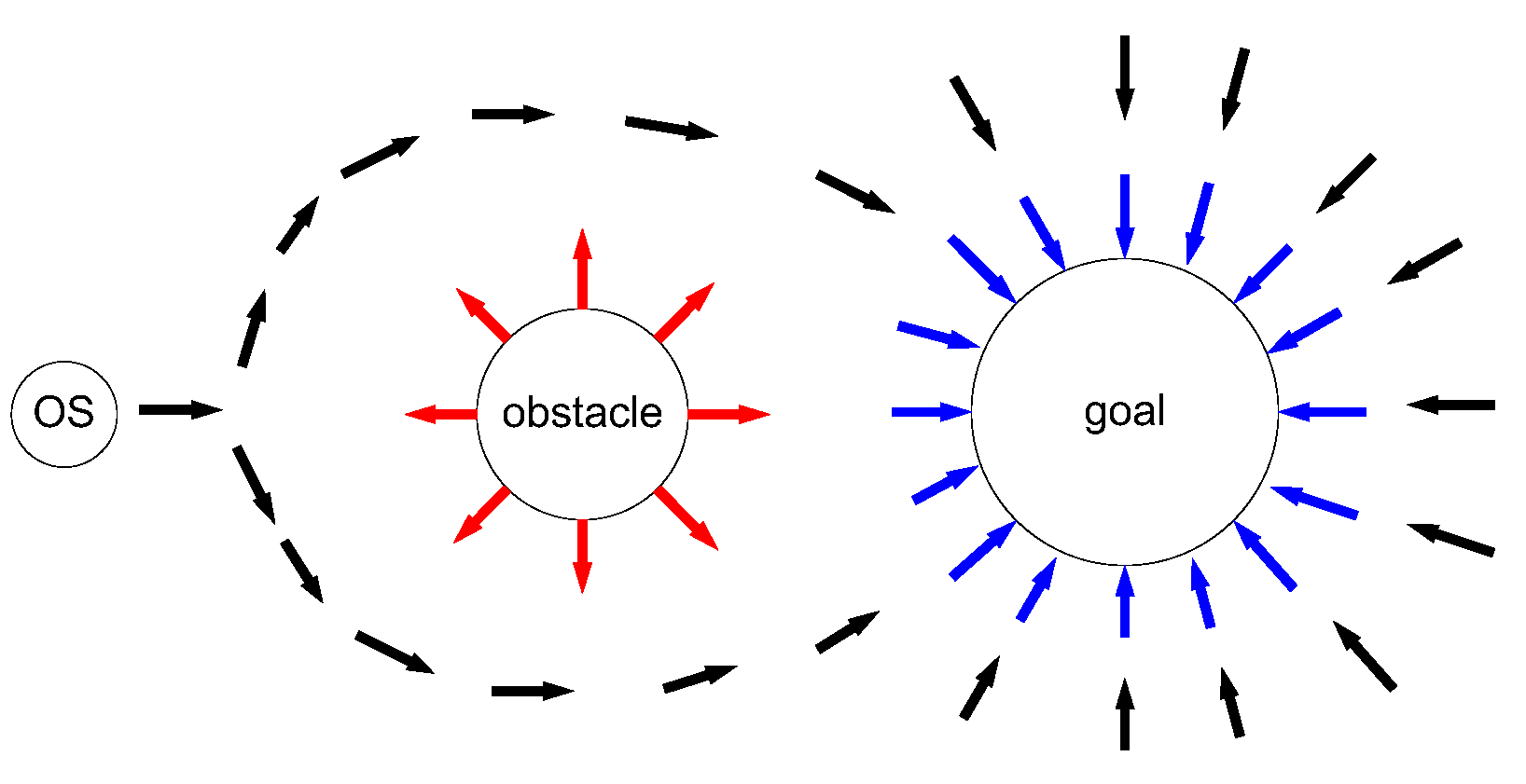
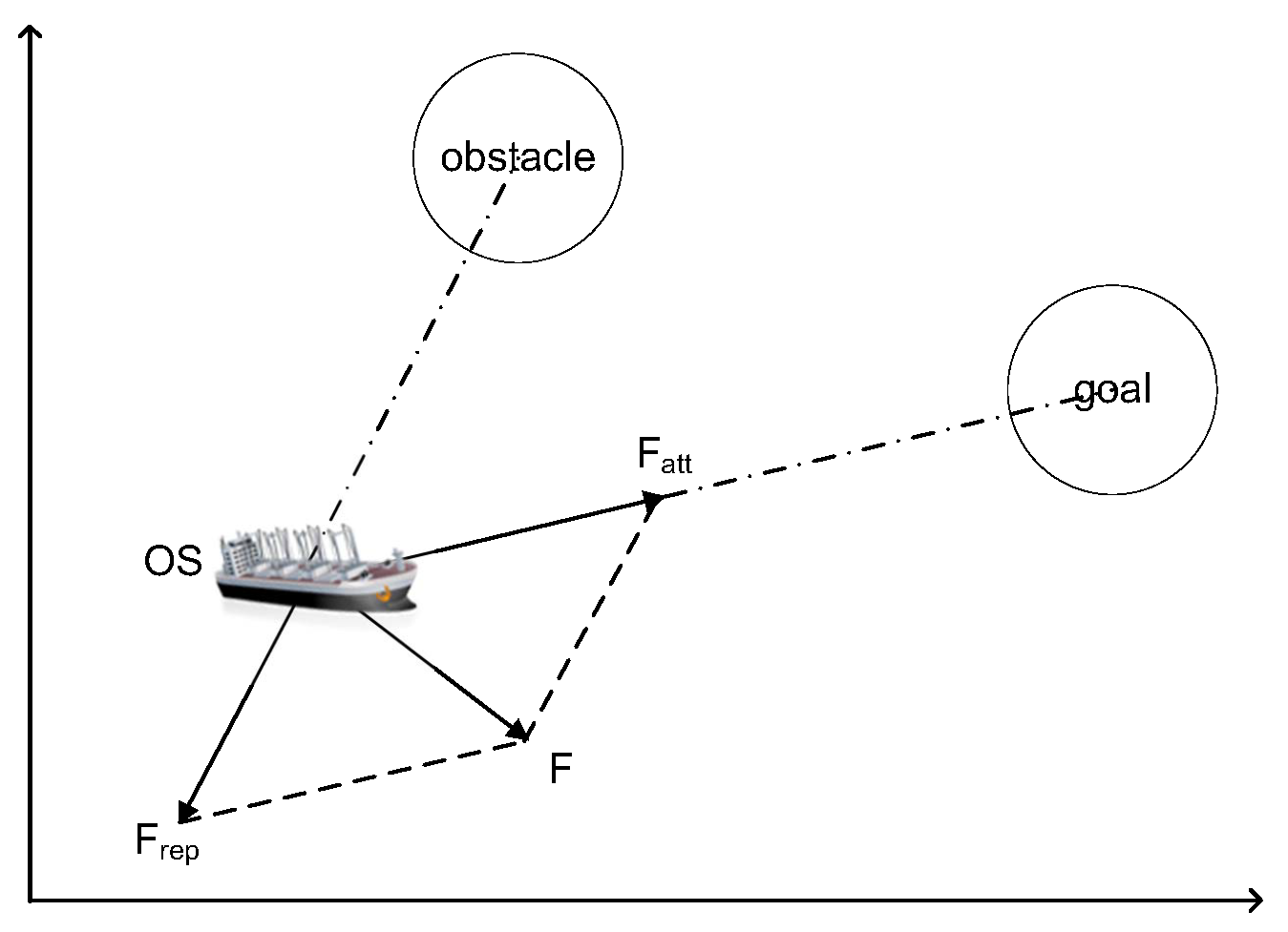
The artificial Potential Field (APF) method is a virtual force method proposed by Khatib in 1986 [27]. In ship domain [28], let own ship (OS) denote the ship, which needs to use the APF method for path planning, and let TSs (target ships) denote the ships which are dynamic ships around the OS to be avoided. In the virtual potential field for ship path planning, obstacles are surrounded by repulsive potential fields to force the ship away, and attractive potential fields surround the goal to attract the ship, shown in Figure 1. Obstacles include dynamic TSs and static obstacles (i.e., island, rocky outcroppings, and shoals). The combined force on the ship is equal to the negative gradient of the total potential field. Under the combined force, the ship sails from a high potential field to a low potential field along the negative gradient direction, shown in Figure 2. , , and F is an attractive force from the goal, a repulsive force function from the obstacle, and the combined force of attraction and repulsion, respectively. Therefore, the traditional APF method can effectively implement obstacle avoidance and path planning of ships. The core idea of the APF method is to find the potential functions under the combined potential of attraction and repulsion. These functions can be represented by the following Equations (1)–(10), based on [27]:
where , , and represent the artificial potential field, the attractive potential field, and the repulsive potential field, respectively; and X is the position of the OS. In addition, the attractive potential field is written as
where is a positive scaling factor for the attractive potential and is the position of the goal; is the distance of the two locations where , , and . We assume that there are obstacles around the OS. Furthermore, the repulsive potential field of the jth obstacle () can be written as:
where is a positive scaling factor for repulsive potential, is the distance threshold for an obstacle to create a repulsion effect on the OS. The selection of the distance will depend on the maximum speed () and the maximum deceleration ability of the OS (). In a two-dimensional space, X = (x, y) is the coordinate of the OS, is the coordinate of the jth obstacle, and is the Euclidean distance between the OS and the jth obstacle. The total repulsive potential field of obstacles is the sum of the repulsive potential fields produced by all obstacles to OS, written as:
where N is the total number of all obstacles. The goal puts an attraction on the OS, attracts OS to approach gradually, and finally arrives. The obstacles repulse OS to avoid collisions. The derivatives of the attractive potential function and the repulsive potential functions are an attractive force function and the repulsive force functions, respectively, written as
where and are the attractive gradient and the jth repulsive gradient function, respectively. and are the attractive force and the jth repulsive force function, respectively. The sum of attraction and repulsion forces on the OS can be expressed simply as the sum of vectors:
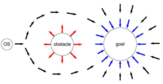
Figure 1.
Diagram of traditional artificial potential field method [27].
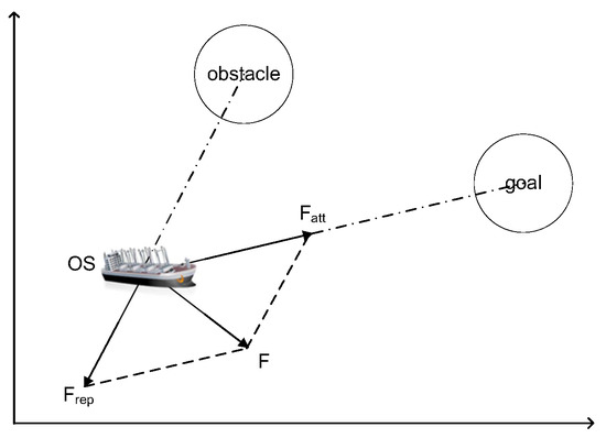
Figure 2.
The force diagram of the OS In traditional artificial potential field [27].
2.2. Modified Artificial Potential Field (APF)
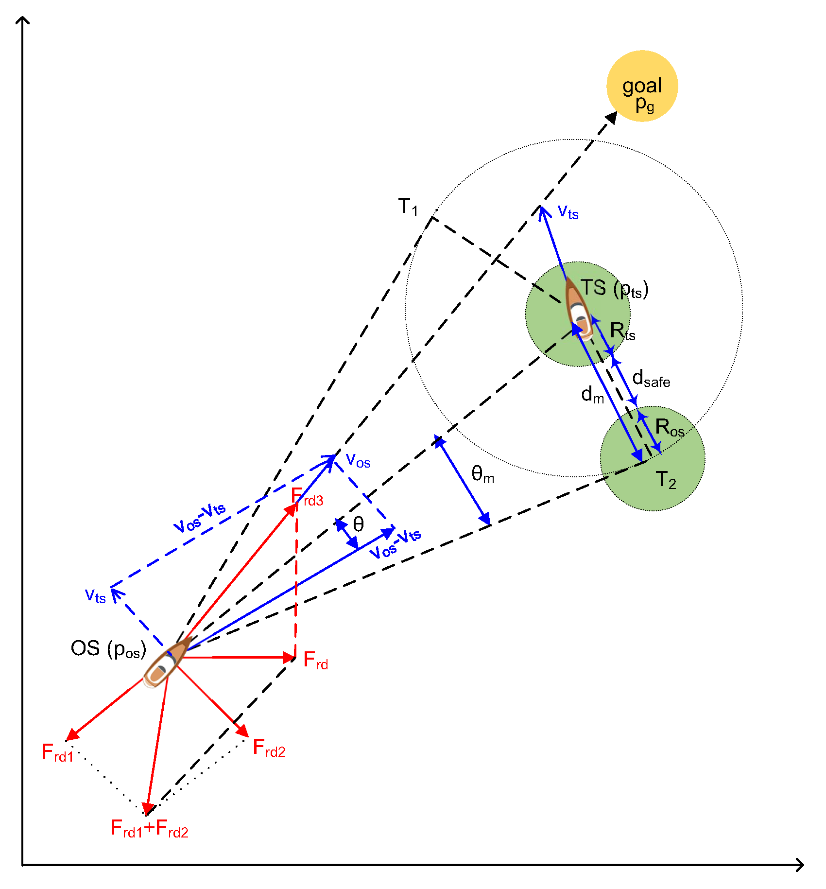
The traditional APF method has the advantages of simple calculation and effectivity. However, the traditional APF method has the problem of local minimum [29]. Meanwhile, APF for path planning of USV also needs to consider collision avoidance with dynamic TSs, static obstacles, and emergency. The authors [12] proposed a modified APF including the modified repulsion potential field function and the corresponding virtual force to solve the dynamic target collision avoidance. They subdivided the repulsive potential field function according to the requirements of International Regulations for Preventing Collisions at Sea (COLREGS), including dynamic TSs, static obstacles, emergencies, and others, which are shown in the equations based on [12]. This paper focuses on the introduction of APF for dynamic TSs, shown in Figure 3. We have
where and are the ship domain radiuses of the OS and TS, respectively; is the sum of , , and the safe distance between OS and TS (). We have
where is the angle between the tangent line of the radius circle of and the vector of the OS to the TS. , , and are the position of the OS, the Ts, and the goal. is the Euclidean distance between the OS and the TS. According to the above equations, the modified attractive and repulsive potential function are shown in Equations (13) and (14).
where is the preset influence range of the TS and is the radius of an artificial safety margin of the OS. and are the speeds of TS and OS, respectively. is the angle between the vector () and the relative speed vector (), and is the relative speed vector from the OS to the TS. = , CR is the sum of and . , , and are the positive scaling factors for the dynamic the TSs, static obstacles, and emergency action, respectively. is the attractive force in term of the position, shown in Equation (15). is repulsive force of the position and the velocities, shown in Equation (19).
where and are the repulsive force from the TS and the attractive force from the goal, respectively, when the obstacles are dynamic TSs. is the repulsive force to make the OS alter course to starboard for TS to meet COLREGS requirements. and are the repulsive force from the obstacle and the attractive force from the goal when the obstacles are static obstacles, respectively. For an emergency action, and are the repulsive force from the obstacles and the attractive force from the goal, respectively. makes the OS avoid collisions from the right or the left side of according to which side of the line the vector is on. This modified APF calculates the steering angle (), desired heading (), and dynamic position () by inputting , , , , , , , , , , , and .
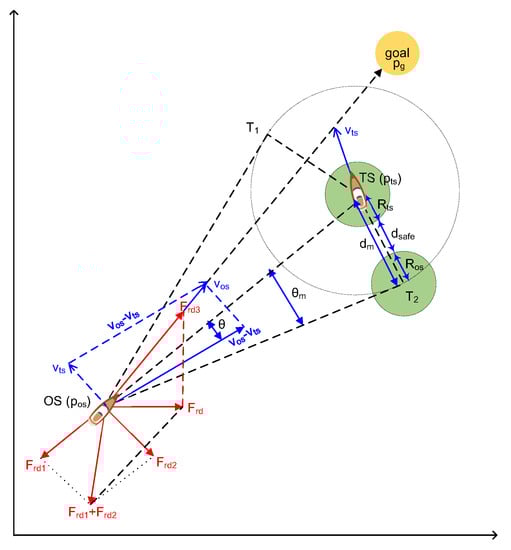
Figure 3.
Modified APF for a dynamic TS [12].
3. GPS Attack Designs and Spoofing Analysis
In this section, we first introduce GPS and attacks on GPS. Then we design a GPS spoofing attack and analyze how the GPS spoofing influences the result of the path planning of unmanned ships based on the APF method in Section 2.
3.1. GPS Introduction
Global Positioning System (GPS) is a satellite navigation system, which provides position, navigation, and timing for land, sea, and air in the world [30]. Furthermore, a GPS is an important navigation device for an unmanned ship [31]. A GPS consists of three parts, including space, control, and a user device. The space part of aGPS consists of 27 GPS satellites (24 active and three standby). The GPS control part consists of one main control station, five detection stations, and three injection stations. The GPS user device part includes a GPS receiver and other devices. The basic principle of a GPS navigation system is to measure the distance between the satellite and the user’s receiver and calculate the receiver’s position by integrating the data of multiple satellites. The GPS signals include a carrier at L1 and L2, Pseudo Random Number (PRN) code at civil code (C/A) and military code (P-code), and navigation data. The GPS signals include raning codes and the navigation message, shown in Figure 4. The GPS system must modulate the ranging code and navigation information onto a carrier frequency before it can be transmitted to the receiver. The frequencies are utilized, including the L1 frequency at 1575.42 MHz and the L2 frequency at 1227.60 MHz. Coarse/Acquisition code (C/A code) is transmitted on the L1 frequency as 1.23 MHz signal. Precision code (P-code) is transmitted on both L1 and L2 frequencies as 10.23 MHz signal.
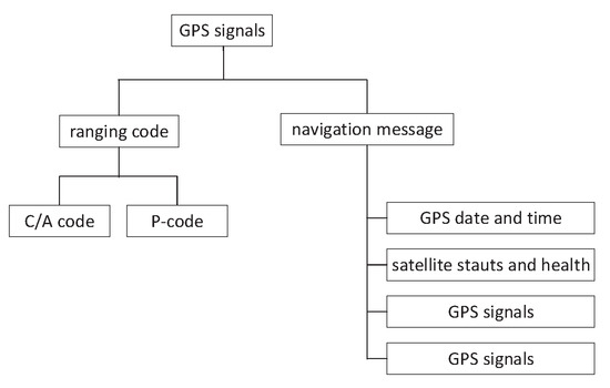
Figure 4.
GPS signal structure.
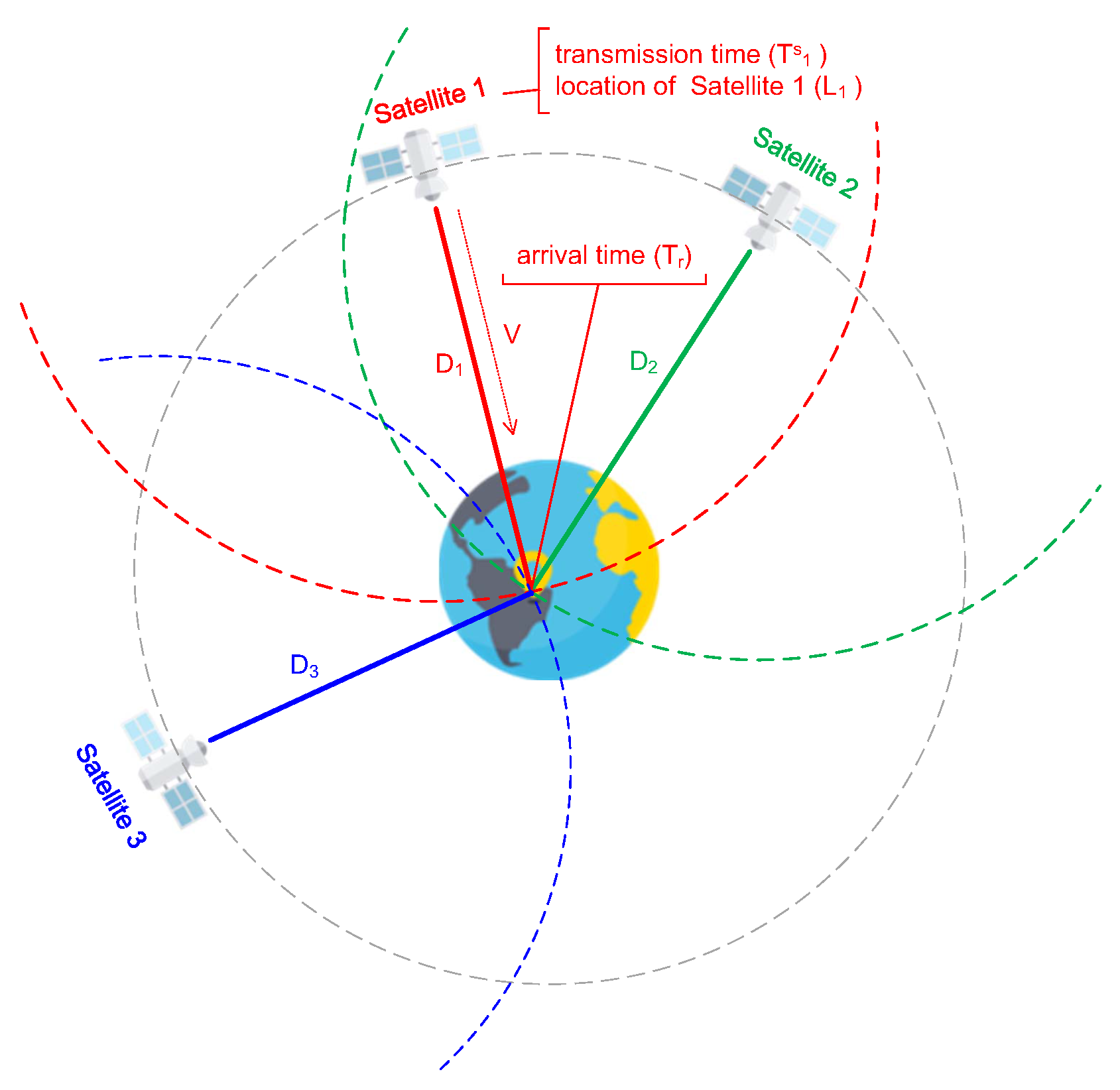
First of all, before we introduce a GPS attack, we need to understand the GPS working principle. Figure 5 shows how a GPS works. Based on [24], let , L, and denote the distance between the i-th satellite and the receiver, the location of the receiver, and the location of the i-th satellite, respectively. is expressed by Euclidean distance as follows:
where = () is the coordinate of satellite in Cartesian three-dimensional coordinate system. Similarly, is the coordinate of the receiver. Equation (20) can be transformed into the following Equation (21):
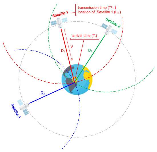
Figure 5.
GPS working principle [32].
The receiver can separate transmission time () and location of the i-th satellite () from the received GPS signals. Meanwhile, the receiver can acquire arrival time () when receiving the GPS signal. GPS signal transmission speed (V) is close to the speed of light. can be expressed by , and V as follows:
where , , and V are known scalars. Combining Equations (21) and (22), we can know that the receiver location (L) can be calculated when at least three satellite signals are received. In geometric space, a satellite defines a transmission circle with radius . At least three of these circles intersect with the earth’s surface, where the receiver is located
In practice, the time between different satellites is synchronous, but the time of different types of receivers is not exact. We assume that is a clock offset between the receiver and exact GPS time system and is the arrival time of GPS signal measured under a common standard. We can get the following equation:
Based on the above, there are four unknown scalars, including , x, y, and z. Therefore, the receiver must receive more than four satellites’ signals to calculate the receiver’s exact location.
3.2. GPS Attacks
As we know, the signal structure, spread spectrum code, and modulation method of civilian GPS signals are public. Military GPS signals are encrypted. Therefore, civilian GPS signals are insecure and may be exploited by some attackers. We focus on GPS C/A code in this paper. GPS attacks are classified into jamming attacks and spoofing attacks.
- A jamming attack happens when a GPS jammer transmits strong jamming signals at the same frequency, which suppress the front-end signal of the GPS receiver so that the GPS receiver loses the ability to work or receive attenuated satellite signals. Jamming attacks have the advantages of simple operation and easy implementation. However, the power required for a jamming signal is large;
- A spoofing attack happens when a GPS spoofer transmits the same or similar signal as a GPS signal to guide the GPS receiver to deviate from the original correct navigation and positioning. Spoofing attacks have the advantages of strong concealment.
Next, we introduce GPS jamming and GPS spoofing in detail.
3.2.1. GPS Jamming
The GPS signals of satellites, measured at the surface of the earth, are very weak. According to IDC-GPS-200 [33], the transmitting power of the L1 signal only guarantees the minimum signal power level of −160 dBW on the earth surface and the minimum signal level of −166 dBW when the L2 signal strength reaches the earth surface. The experiment result of Lincoln Laboratory [34] shows that a jammer with a power of 1 W can make the receiver of C/A code within 85 km out of work. If the jamming power is increased by 6 dB, the jamming distance is doubled. Therefore, the GPS is vulnerable to jamming, resulting in difficulties in acquiring navigation data. GSP jamming technologies based on bandwidth () is classified into three types, including Continuous Wave (), Narrowband (), and Wideband (), where < 100 kHz, 1.023 kHz, 10.23 MHz. The GPS signal acquisition is a search process to determine whether the satellite signals exist or not. Based on [35], the detection probability of GPS signal is proportional to the carrier to noise ratio . A jammer broadcasts on the same frequency to reduce , i.e., increasing noise (). Therefore, the victim receiver cannot acquire GPS signals normally. A simple GPS jamming system, including a power amplifier, an antenna of a GPS simulator, and an RF signal transmitter, can jam GPS receivers. Many papers have detailed introduction, such as [36,37,38].
3.2.2. GPS Spoofing
Compared with GPS jamming, GPS spoofing is more dangerous to ship navigation because it is surreptitious [32]. An attacker makes the receiver believe that it is at the wrong location. It is a very dangerous situation for the path planning of USV based on APF. GPS spoofing is classified into production spoofing and repeater. GPS production spoofing refers to the receiver-spoofer generating spoofing signal, Pseudo Random Number (PRN), and navigation message, which the victim GPS receiver can receive. GPS repeater spoofing refers to the spoofer modifying, modulating, and amplifying the received GPS signal or sending it out after a delay. The production spoofing for C/A is possible because C/A signals are public and not authenticated, but it is difficult for P-code. Based on [39], we can know the composite signal received at the antenna of a GPS receiver is = + + , where , , and are the authentic signal, spoofing signal, and noise signal, respectively. When , the signal received at the antenna of GPS receiver can be approximated by . The spoofing signals generated by the GPS spoofer successfully override the authentic GPS signals. The attacker can transmit its GPS signals using the publicly known GPS parameters by a simple GPS generator. Although this approach can spoof the receiver, the spoof signals look like noise to the receiver [40].
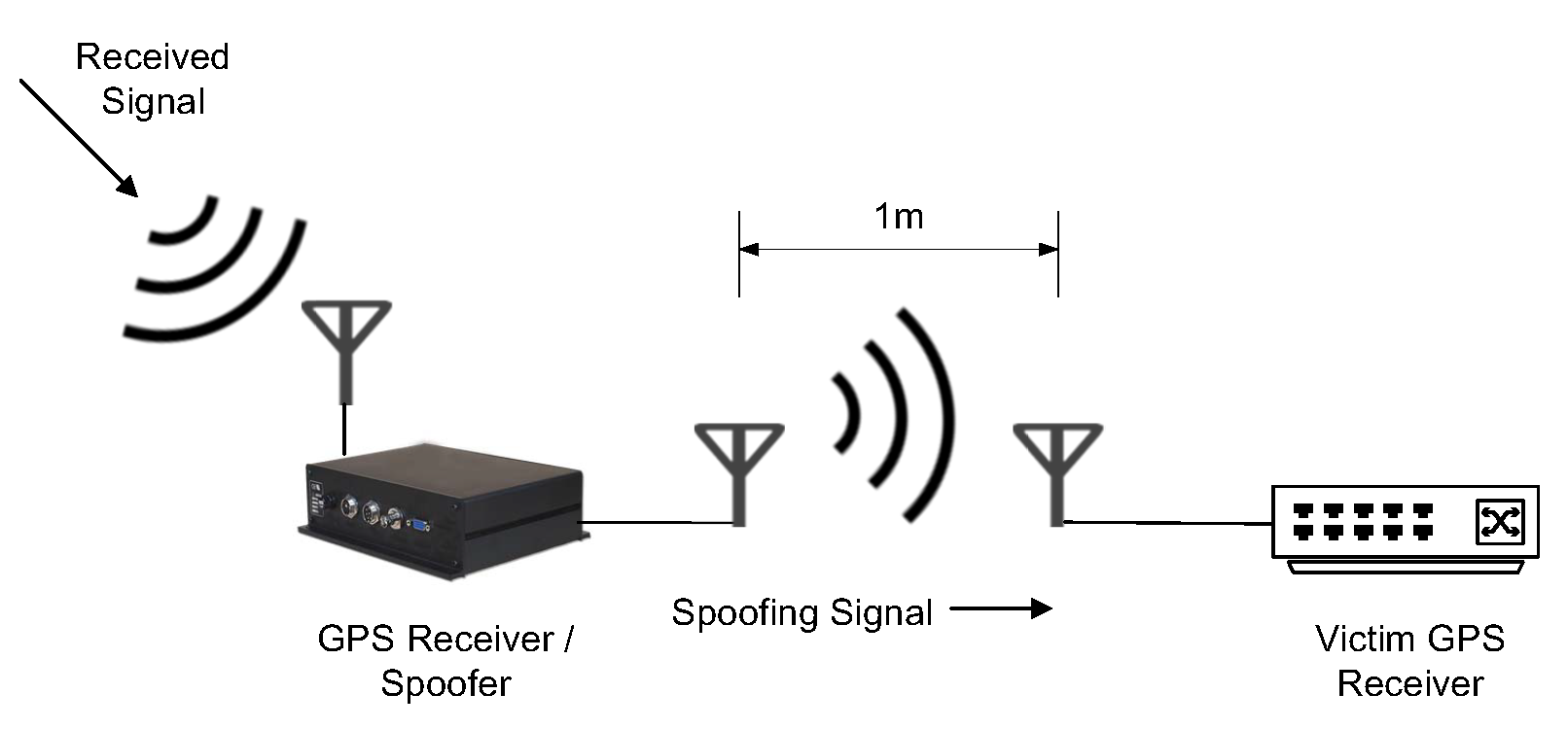
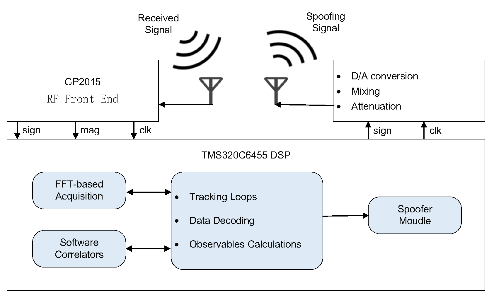
Next, we focus on GPS repeater spoofing. The attacker can delay and modify the content of received GPS signals to spoof the victim GPS receiver into calculating a false location, such as a receiver-spoofer designed by Humphries [41], as shown in Figure 6 and Figure 7. Based on Equation (28) in Section 3.1, if the attacker changes the arrival time of GPS signals () by delaying the transmission of received signals, it will eventually lead to an inaccurate receiver position. On the other hand, if the attacker changes the content of GPS (i.e., transmission time or location of the satellite) according to its intention, the ship which depends on GPS for path planning navigates to the position set by the attacker, causing a greater danger. The paper [40] introduces that the Cornell GRID receiver can simultaneously track 12 C/A channels and generate 8 C/A spoofing channels. Such equipment coupled with the simple RF hardware can implement GPS spoofing. In case of GPS spoofing or signal loss, the speed information obtained by the Inertial Navigation System (INS) is used to assist the GPS receiver tracking loop in implementing navigation and positioning functions. The INS is a technology used to obtain instantaneous velocity and instantaneous position data by measuring acceleration and automatic integration operation, one of the key equipment for ships. When the GPS is combined with the INS, it can still complete the output of position and speed in the face of GPS jamming. However, in the face of GPS spoofing, it will lead to the divergence of the GPS/INS navigation system and destroy the overall performance of the integrated navigation system. The integrated navigation system supervises the GPS during unmanned ships’ navigation. When there is a difference between the position information calculated from the GPS and the position information estimated from INS according to the previous time, the integrated system will suspect that the GPS signal has been spoofed. Therefore, in GPS spoofing, it is necessary to gradually induce the unmanned ships to deviate from the course step by step. Lidar and navigation radar are the main means of ship obstacle avoidance detection. Similarly, GPS spoofing will affect the path planning after multi-source data fusion from lidar, radar, and sensors.
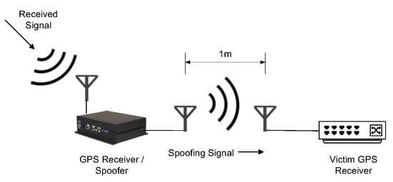
Figure 6.
A Spoofing attack via a portable receiver-spoofer [41].
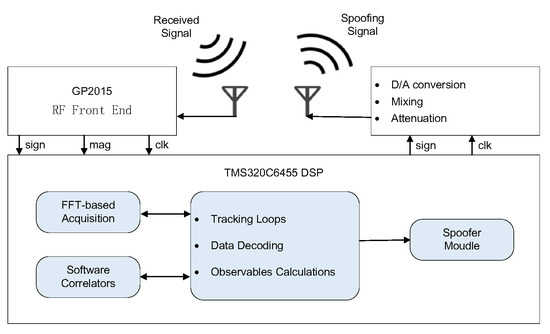
Figure 7.
The architecture of a receiver-spoofer [41].
3.2.3. Designing a GPS Attack
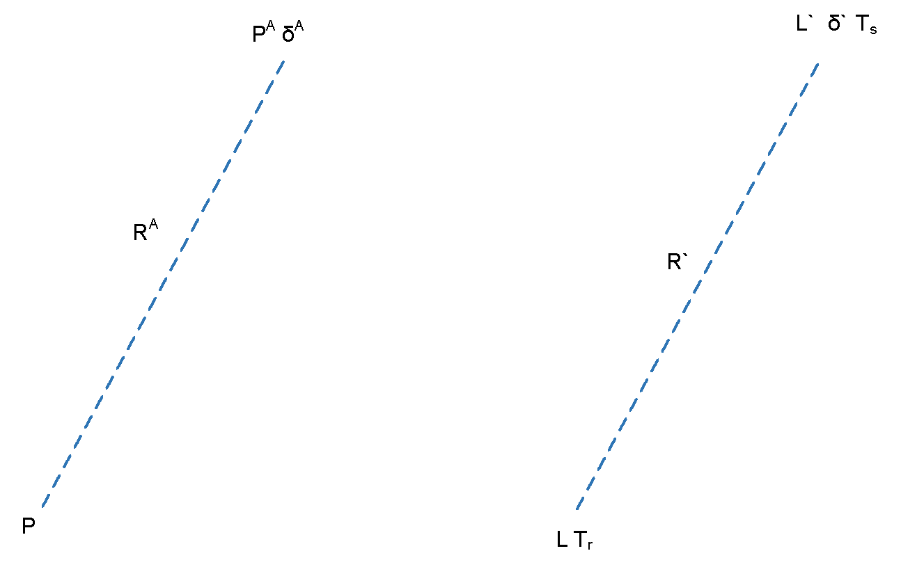
We design a GPS spoofing attack on a single GPS receiver, which can be seen in Figure 8. We assume that the attacker uses a GPS spoofer to attack a victim’s GPS receiver. , , and are the physical location of the receiver, the physical location of the attacker, and the transmission time offset of the attacker, respectively. From the attackers’ perspective, the expected pseudo-range () that the receiver in location P calculates based on the attacker’s signals is as follows.
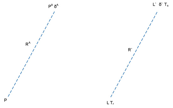
Figure 8.
Perspective of attackers and receivers.
In the perspective of the receivers, the pseudo-range (R) is calculated according to the signals of impersonated satellite location (L), the time offset (), and receivers location determined by an attacker (L) as follows.
At the same time, the pseudo-range (R) can be calculated by transmission (T) and the receiving time (T) of GPS spoofing signals as follows.
If the attacker (A) wants to spoof the GPS receiver (G) successfully, this requires R = R.
In the term of the attack on GPS C/A, the attacker can set the location of satellite = (, , ) and the physical location of the attacker = (, , ) in advance. The attacker brings = and = into Equation (32) to solve for , and = .
3.3. Spoofing Analysis
Next, we analyze how the above GPS spoofing influences the result of the path planning of unmanned ships based on the APF method in Section 2. As we see in the above subsections, GPS signals received by the GPS receiver of an unmanned ship is determined by the attacker, conducting a GPS spoofing attack on the unmanned ship. We take an obstacle as an example to explain the influence of GPS deception on the path planning results of the APF method. Let denote the physical position of the unmanned ship, denote the obstacle coordinates, denote the goal coordinate, denote the positive scaling factor for attractive potential, and denote the positive scaling factor for repulsive potential. The GPS receiver of the unmanned ship receives the GPS data of the ship, i.e., = X + = (x + , y + ). Additionally, is the position offset added by attackers during GPS spoofing. In conclusion, the Equations (2)–(10) of the artificial potential field method in Section 2 is changed into the following Equations (29)–(34). In the case of GPS spoofing, the attractive potential field (X) is rewritten as:
Next, we analyze the change of the repulsive potential field in the case of GPS spoofing. When the distance between the OS and the obstacle is less than or equal to the influence radius () of the repulsion force generated by the obstacle, the repulsive potential field of the obstacle can be written as:
When the distance between the OS and the obstacle exceeds the radius of influence () of the repulsion force generated by the obstacle, we think that the repulsive potential field of the obstacle is 0. We superimpose attractive potential field and repulsive potential field to form artificial potential field , and the equation is shown as follows.
As we know, the path planning of the artificial potential field method is to move forward along the negative gradient direction from the current position until the gradient is 0. The derivatives of the attractive potential function and repulsive potential function are attractive force function and repulsive force function, which can be written as:
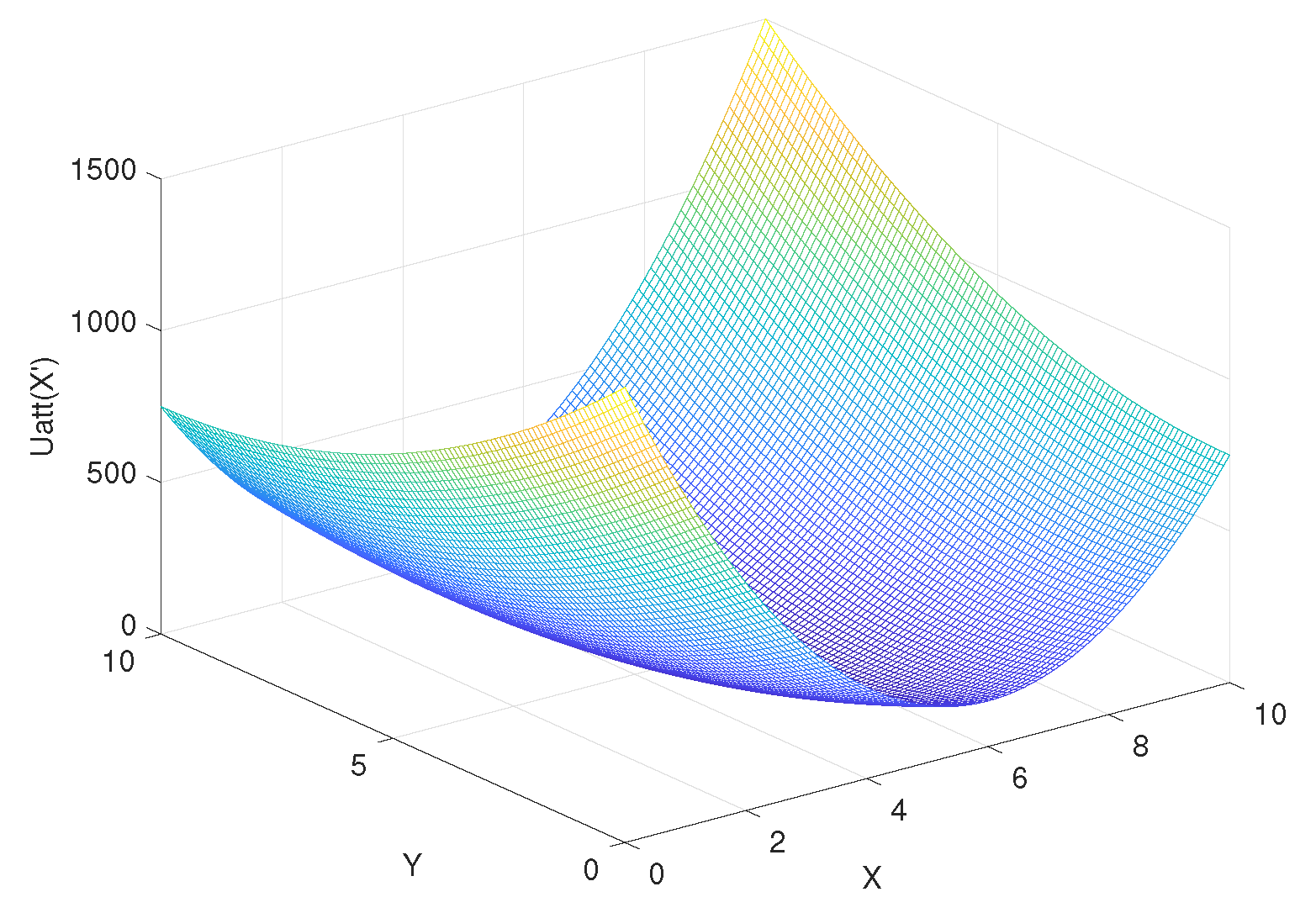
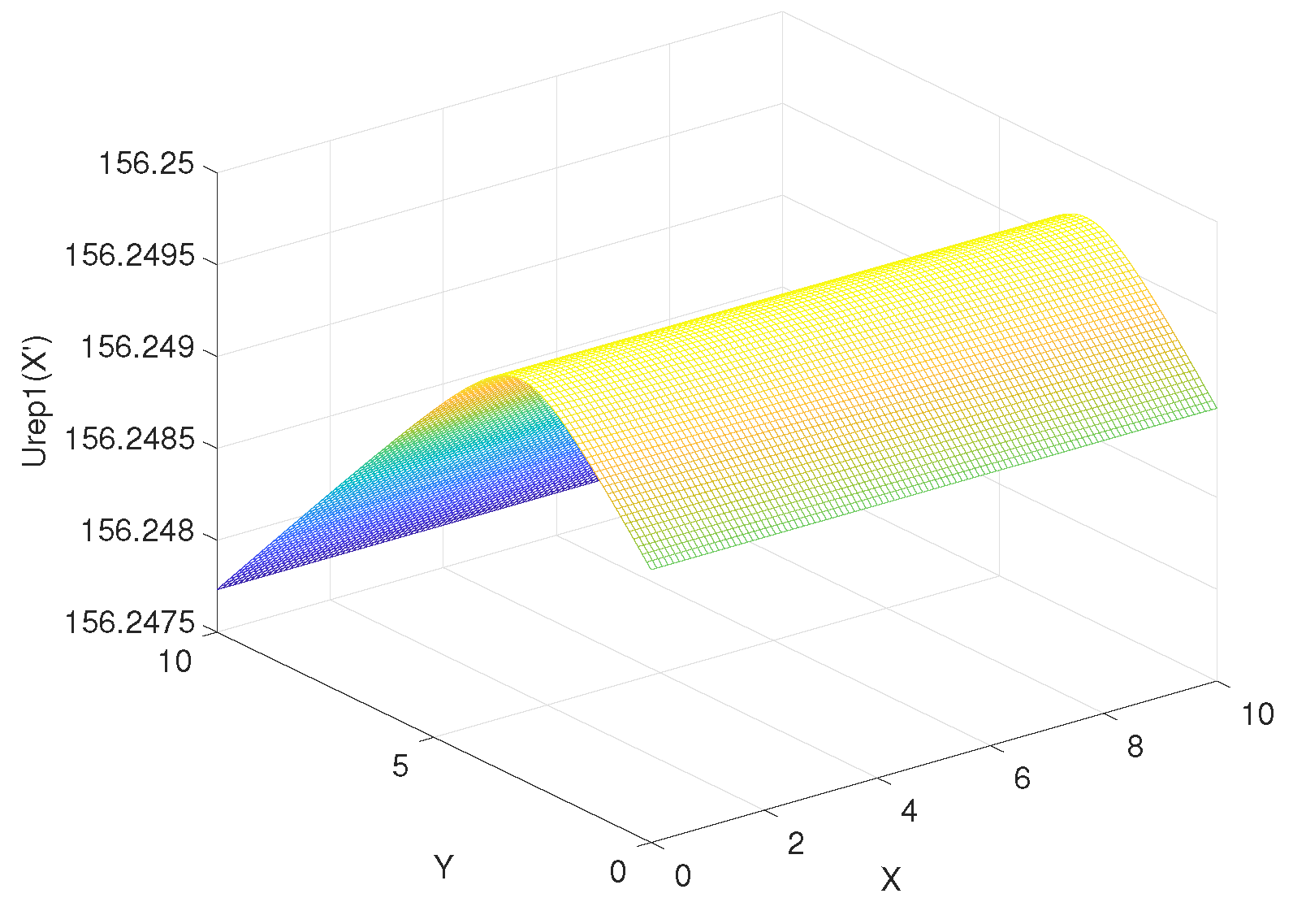
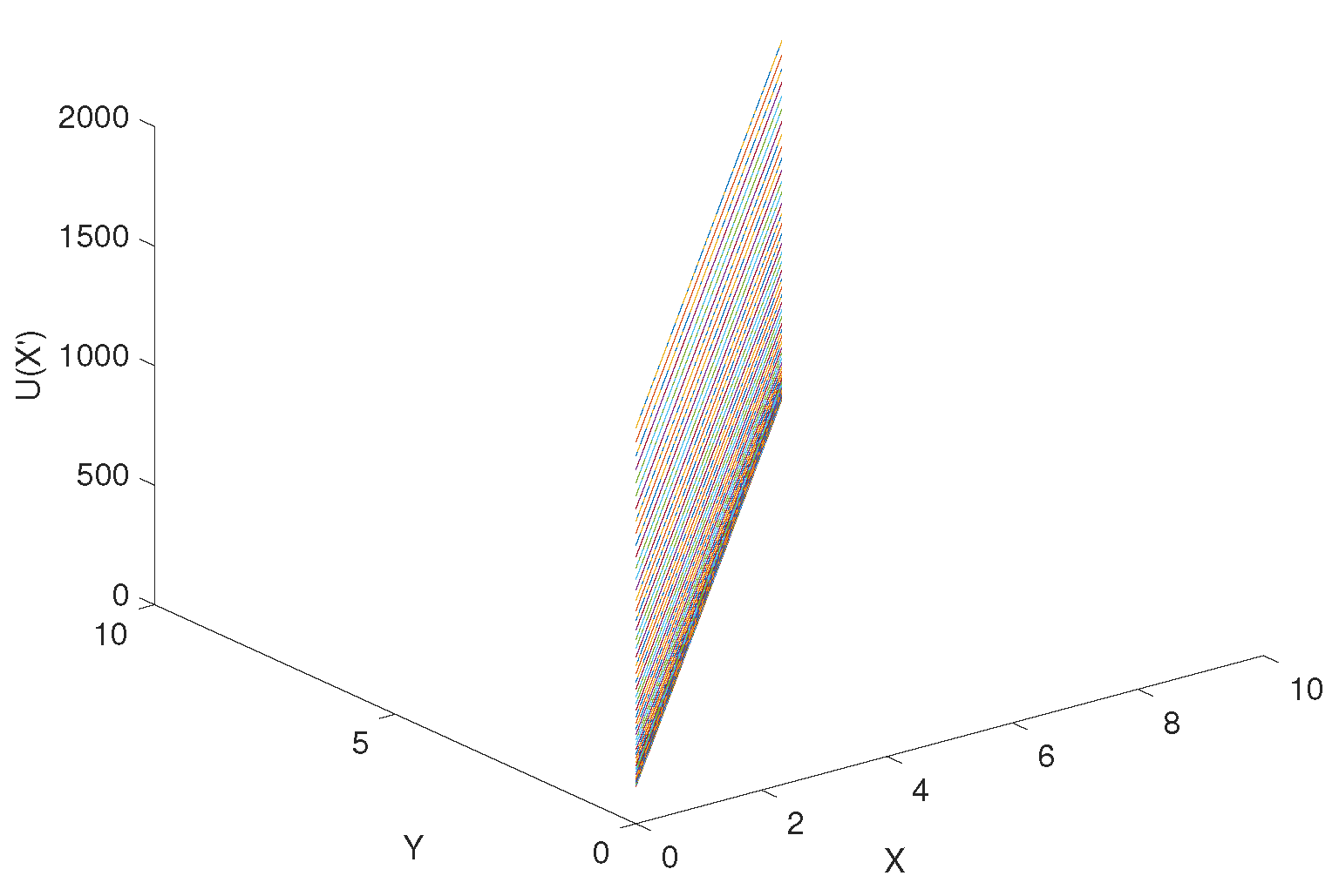
According to Equation (34), assuming that x and y are from 0 to 10, the step is 0.1, is from 0 to 10, the step is 0.1, the coordinate of goal = (10, 10), the coordinate of obstacle = (4, 8), the attraction gain = 50, the repulsive gain = 15, and the influence distance of obstacles = 0.4, we can get the curve of the influence of change rate on , as shown in Figure 9. Similarly, according to Equation (35), the curve of delta change rate on can be obtained, as shown in Figure 10. The influence of change rate on the resultant force of attraction and repulsion is shown in Figure 11.
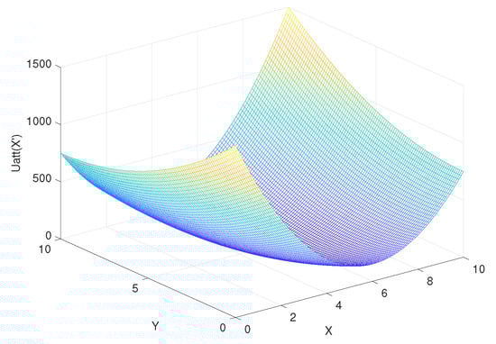
Figure 9.
The influence of change rate on .
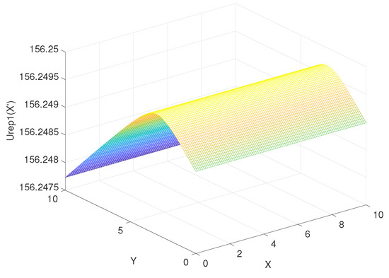
Figure 10.
The influence of change rate on .

Figure 11.
The influence of change rate on the resultant force of attraction and repulsion.
4. Experiments
To verify the feasibility and practical effect of GPS spoofing on the APF method in the previous section, we first use HackRF ONE as a GPS spoofer to simulate GPS spoofing, as shown in Figure 12. Then we use GPS spoofing data to simulate the path planning of the APF method. The hardware system of the GPS spoofing test includes HackRF ONE, GPS external clock, and a 700–2700 Mhz antenna, as shown in Figure 13. The software platform is Ubuntu 64 bit (18.04), and the GPS receiving terminal is Xiaomi 6 mobile phone, as shown in Table 1. We use Matlab to simulate the path planning of the APF method to test the influence of GPS spoofing on path planning.
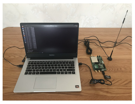
Figure 12.
A simple GPS spoofer.
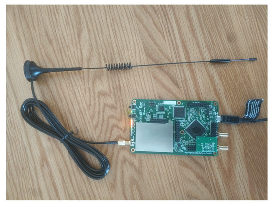
Figure 13.
The test system of the hardware.

Table 1.
Experimental environment of GPS spoofing.
4.1. GPS Spoofing Simulation
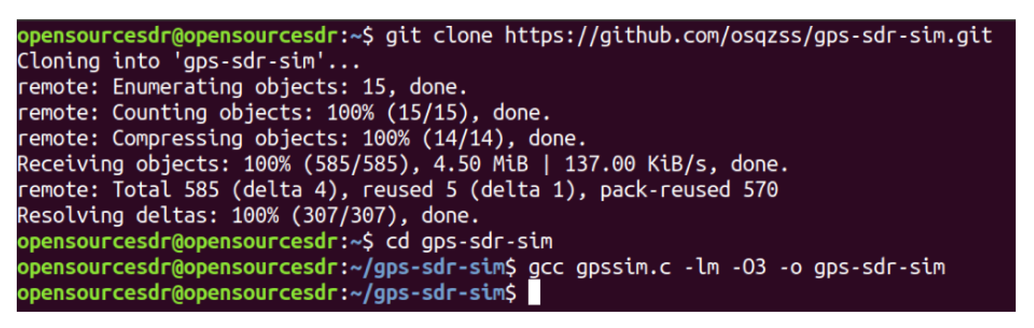
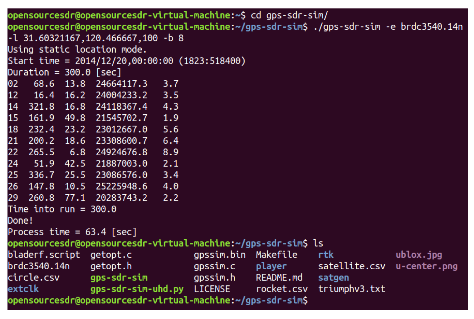
We use GPS-SDR-SIM as a GPS signal generator code, which can produce spoofing GPS signals. GPS-SDR-SIM is an open-source GPS generator project. To make it easier for readers to understand GPS spoofing, we introduce the process of GPS spoofing step by step. We download and compile the GPS simulator code from GitHub, as shown in Figure 14. Then, we can generate GPS longitude and latitude information that we want to spoof through online tools and generate GPS simulation data through GPS simulator according to this longitude and latitude information, as shown in Figure 15. Among them, 31.60321167 and 120.4666667 are the GPS longitude and latitude of spoofing to be transmitted to the GPS receiver. After the execution of the above command, the gpssim.bin file is generated, which saves the GPS spoofing data generated by the simulation code, as shown in Figure 16. The GPS test app for mobile phones is GPS Test Plus. Before starting the GPS spoofing attack, open the app of GPS Test Plus and check the physical position of the mobile phone, as shown in Figure 17.
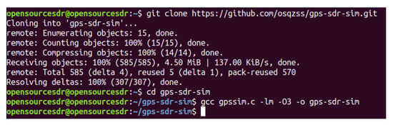
Figure 14.
GPS-SDR-SIM download and compile.
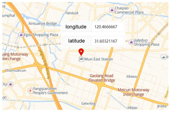
Figure 15.
GPS spoofing location.
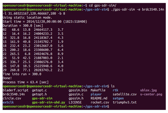
Figure 16.
Generation of GPS spoofing data.
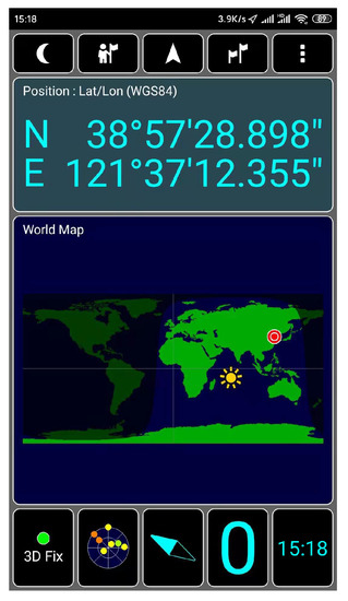
Figure 17.
Physical position of test mobile phone.
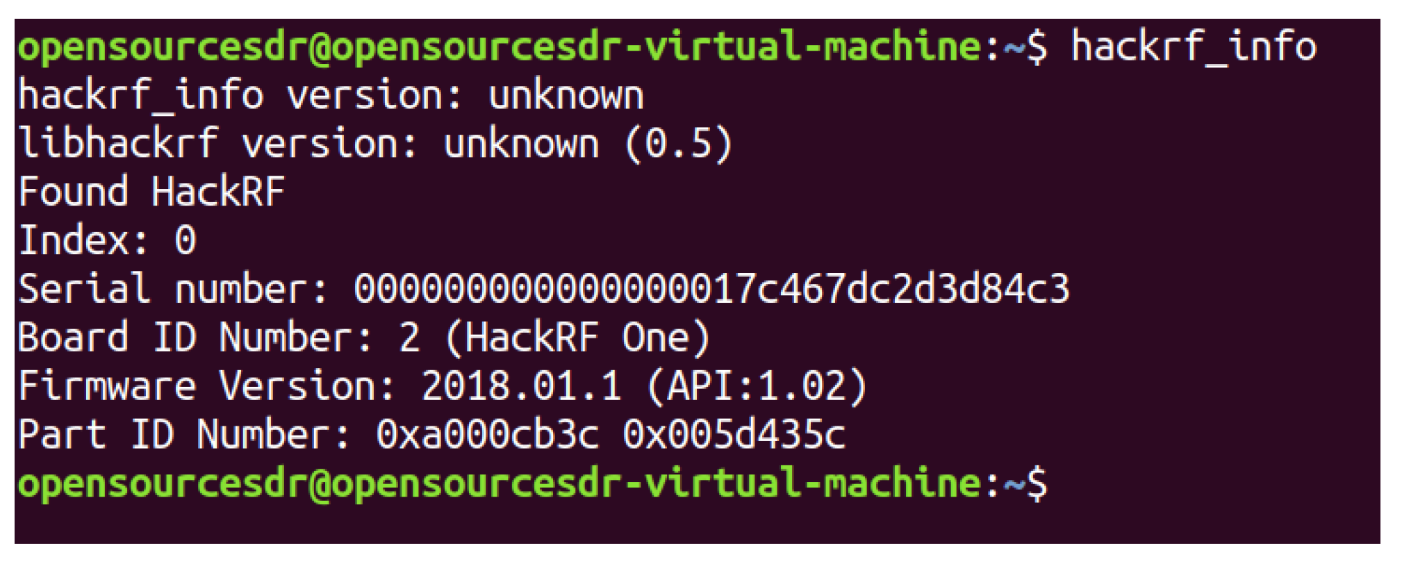
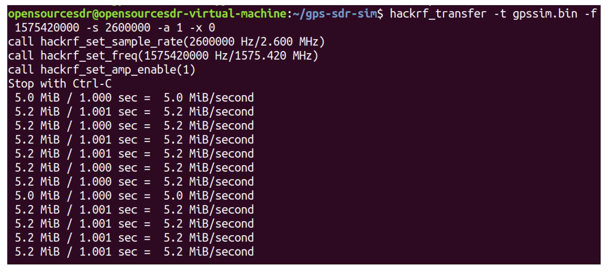
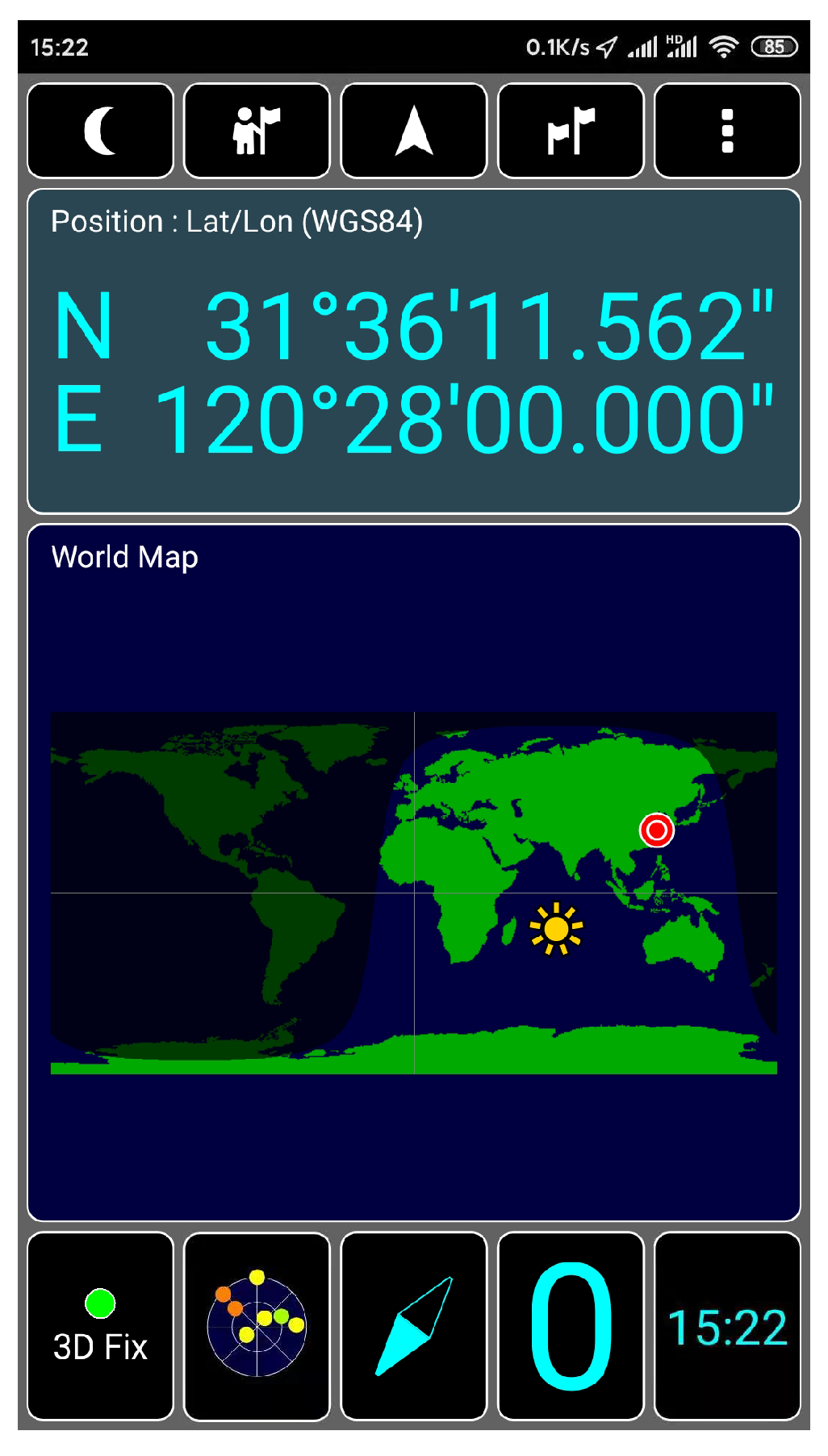
We connect HackRF ONE to the computer with USB and test whether the host installation is successful in the shell terminal of Ubuntu, as shown in Figure 18, which proves that the hardware system of HackRF ONE has been successfully connected to the computer. HackRF ONE is a full open-source hardware and software project that can provide Software Defined Radio (SDR) solutions. The wireless communication protocol based on software definition can replace the hardware connection so that the frequency band, air interface protocol, and function can be upgraded through software download and update without replacing the hardware. We use HackRF ONE to transmit the fake GPS data we simulated above, as shown in Figure 19. After waiting for 3–4 min, we open the app of GPS Test Plus and find that the mobile phone position has been changed to a fake GPS spoofing position, as shown in Figure 20.
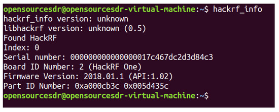
Figure 18.
Test whether the host is installed successfully.
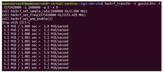
Figure 19.
The fake GPS data transmission.

Figure 20.
Spoofing position of test mobile phone.
4.2. APF Simulation
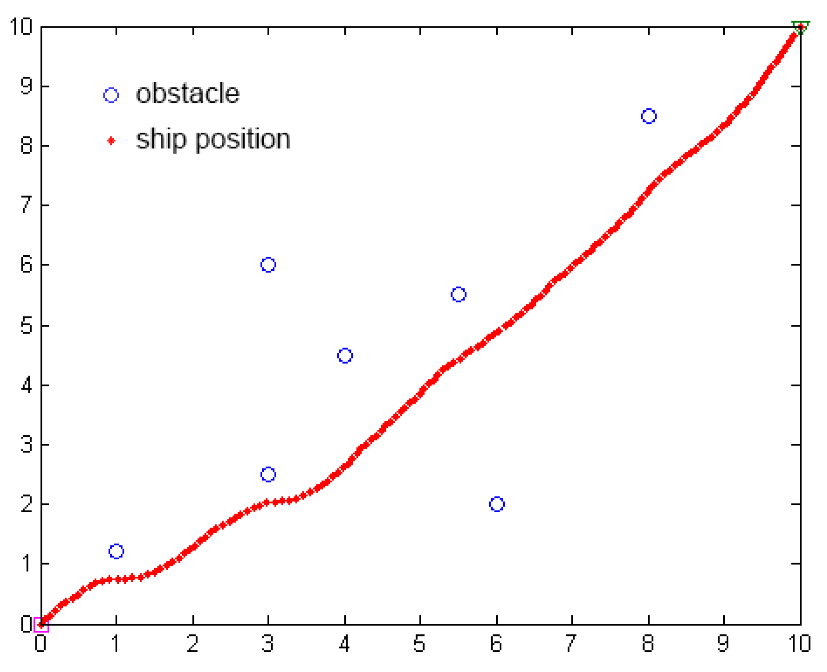
We use Matlab to simulate the path planning of the unmanned ship using the APF method, as shown in Figure 21. The algorithm needs to set the start position, goal position, obstacle position, gravity and repulsion gain coefficient, obstacle influence distance, step, and iteration times.
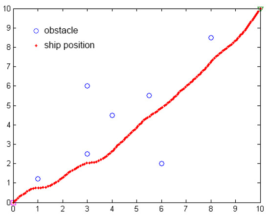
Figure 21.
The simulation of path planning of APF.
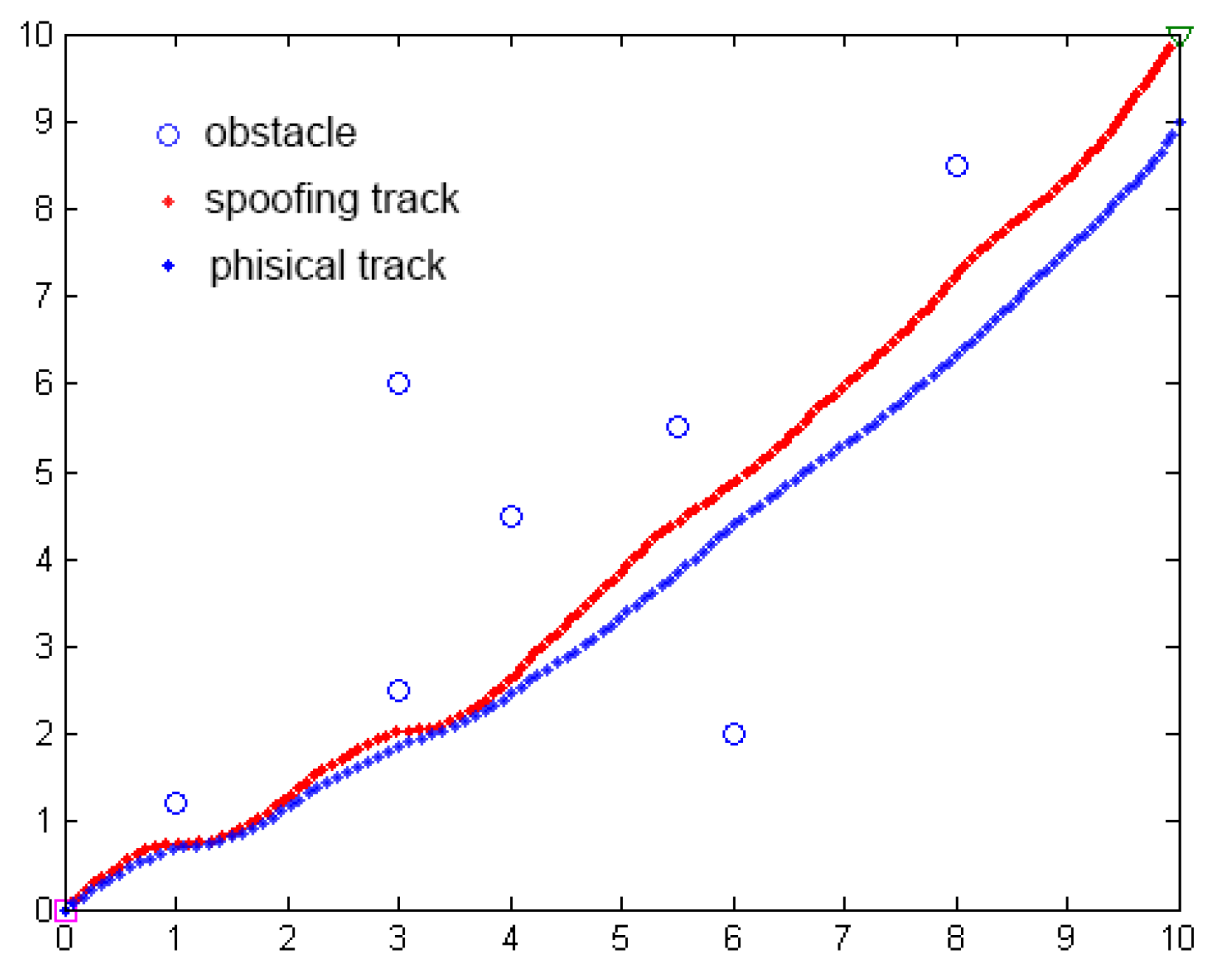
The purpose of a GPS spoofing attack based on the APF method is to cause lateral deviation in the position of the ship’s navigation trajectory so that the ship deviates from the original path planning, as shown in Figure 22.
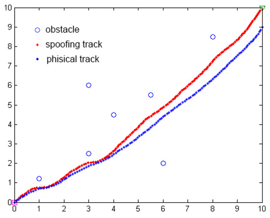
Figure 22.
Comparison of path planning simulation before and after GPS spoofing attack based on APF.
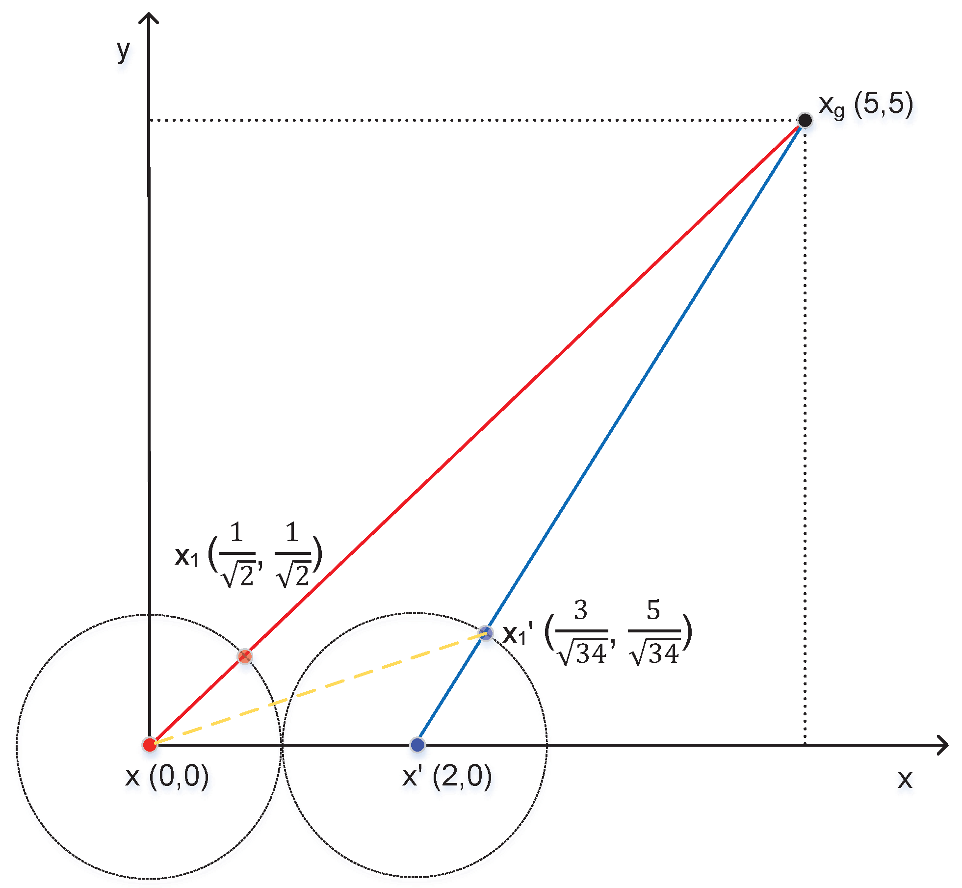
We take a practical example to illustrate the harm of GPS spoofing to unmanned ships using the APF method for path planning. Without the repulsive force of obstacles, we assume that the physical location of OS , the false location of OS , the goal location , and the step is 1, shown as in Figure 23. Without GPS spoofing, the next position of OS based on APF is . Under GPS spoofing, the next position of OS based on APF is . In conclusion, GPS spoofing can cause the yaw of unmanned ships using the APF method for path planning.
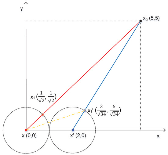
Figure 23.
An APF example.
In the environment of both attraction of goal and repulsion of an obstacle, the attacker can influence the result of path planning based on the APF method through GPS spoofing. We use a practical example to illustrate the influence of GPS spoofing on path planning results by the APF method. In the Cartesian coordinates, we assume that = (10, 10) is position of the goal, x = (0, 0) is the initial position of OS, and are the positions of the first obstacle and the second obstacle, respectively. and are the attraction gain and the repulsive gain, respectively, is the step length of OS. is the influence distance of obstacles. When the distance between the obstacles and OS is greater than this distance , the repulsion force is 0. is the angle between the line from the position of OS (x) to the goal () and the x-axis, is the angle between the line from the position of OS to the first obstacle () and the x-axis, is the angle between the line from the position of OS to the second obstacle () and the x-axis. First of all, we calculate the values of , , and according to the following formulas.
We assume that and are the components of the attraction of the goal on the OS in the x and y directions. We calculate the x and y-axis components of the attraction of goal on the OS as follows.
and are the repulsive forces of the first and second obstacles for the OS, respectively. , , and are the components of the repulsive force on the x and y axes, respectively. and are the resultant forces in the x and y directions, respectively. is the angle between the resultant force and the x-axis. Since the distance between OS and the first obstacle is greater than , the repulsive force of the obstacle on the OS is 0. We calculate the repulsive forces of the second obstacle on the OS as follows.
We calculate the components of the repulsive force of the obstacles on the OS in the x and y directions as follows.
The resultant forces in the x and y directions are as follows.
We calculate the next position (, ) in the path planning of OS as follows.
According to the above formulas, if the position of OS is , the next position of OS calculated by the APF algorithm is . If the attackers change the position of OS by the GPS spoofing, we find that the next position of path planning results of OS will be changed, shown in Table 2. By analyzing these data, we can see that the farther the false position is from the physical position, the greater the coordinate change of the next position of OS. To prevent GPS spoofing from being found, the false position needs to be as close to the physical location of OS as possible and changes continuously with time.
Table 2.
Data relationship between false positions and next positions of OS.
5. Conclusions
At present, the research on path planning of unmanned ships assumes that the data from GPS receivers are reliable. However, the security and authenticity of the data collected by the front end of the unmanned ship are very important. Once the path planning algorithm uses inaccurate or even false data, it will lead to ship collision, grounding, or deviation from the course, causing serious economic losses and causing great security risks to other sailing ships. This paper designs a method where attackers transmit the fake position of ships through GPS spoofing to influence path planning based on APF. Experiments have studied and verified the feasibility of using a simple and economical GPS spoofing device to implement GPS spoofing. The experiments in this paper show that GPS spoofing for path planning of unmanned ships based on the artificial potential field algorithms is feasible without the interference of other factors. Finally, attackers make unmanned ships deviate from the target point through GPS spoofing.
This paper mainly focuses on the impacts of GPS spoofing on the path planning of unmanned ships. At present, there are few papers on the impacts of GPS spoofing on the path planning of unmanned ships. Moreover, there are no large-scale practical application examples of unmanned ships. Limited by the experimental environment and conditions, we cannot test the impacts of GPS spoofing on real unmanned ships since modifying the GPS signal for such ships is very dangerous. We could not get permission to conduct such an experiment even through our organization’s own ships. According to the GPS spoofing steps proposed in this paper, we test the GPS transmitting and receiving devices through experiments. It can be verified that the GPS spoofing method in this paper can also be implemented on real unmanned ships.
Unmanned ships have great advantages in economy, safety, and society, including reducing the operation cost of the ship owner, reducing the cost of personnel on board, reducing the loss caused by human error risk, and reducing the threat of pirates to the personal safety of the crew. In the future, unmanned ships will play an important role in maritime cargo transportation and the military field. There are many sensors and electronic devices on the unmanned ship to collect the dynamic data of navigation and environment, which need to be transmitted to the shore-based control center through communication networks. There may be data delay and packet loss in network transmission, which will affect the real-time monitoring and remote control of the shore-based control center. Moreover, many sensors and electronic devices with open communication protocols, unified standards, and a lack of effective security protection are deployed on unmanned ships, which will bring more potential network attacks and increase the possibility of network attacks on unmanned ship systems. Once an unmanned ship is attacked by the network or the network security management is improper, the shipowners, port operators, and their insurance companies will face a great risk of loss, such as ship collision, grounding, or deviation from the course, which will not only cause serious economic losses but also cause security risks to other ships. Therefore, the network security of unmanned ships is very important for the development of unmanned ships. Finding these security vulnerabilities and problems can be targeted to study the corresponding detection and defense strategies to minimize the loss. Additionally, we will consider inertial navigation systems and means of monitoring and measuring the distance to obstacles as our future work.
Author Contributions
J.W.: performed the experiment and wrote the manuscript; Y.X.: supervised the first author’s work and contributed to the conception of the study, drafting the work, and revising it critically for important intellectual content; T.L.: contributed significantly to analysis and manuscript preparation; C.L.P.C.: contributed significantly to analysis and manuscript preparation. All authors have read and agreed to the published version of the manuscript.
Funding
Jia Wang and Tieshan Li’s work is supported in part by the National Natural Science Foundation of China (under Grant Nos. 51939001, 61976033); the Liaoning Revitalization Talents Program (under Grant No. XLYC1908018); the Natural Science Foundation of Liaoning (2019-ZD-0151).
Conflicts of Interest
The authors declare no conflict of interest.
References
- Wikipedia. Unmanned Surface Vehicle. Available online: https://en.wikipedia.org/wiki/Unmanned_surface_vehicle (accessed on 16 November 2020).
- Gao, X.; Li, T.; Shan, Q.; Xiao, Y.; Yuan, L.; Liu, Y. Online optimal control for dynamic positioning of vessels via time-based adaptive dynamic programming. J. Ambient. Intell. Humaniz. Comput. 2019, 1–13. [Google Scholar] [CrossRef]
- Rødseth, Ø.J.; Burmeister, H.C. Developments toward the unmanned ship. Proc. Int. Symp. Inf. Ships–ISIS 2012, 201, 30–31. [Google Scholar]
- Yang, Y.; Xiao, Y.; Li, T. A Survey of Autonomous Underwater Vehicle Formation: Performance, Formation Control, and Communication Capability. IEEE Commun. Surv. Tutor. 2021, 23, 815–841. [Google Scholar] [CrossRef]
- Kim, J.; Kim, S.; Choo, Y. Stealth path planning for a high speedtorpedo-shaped autonomous underwater vehicle to approach a target ship. Cyber-Phys. Syst. 2018, 4, 1–16. [Google Scholar] [CrossRef]
- Wang, J.; Xiao, Y.; Li, T.; Chen, C.P. A Survey of Technologies for Unmanned Merchant Ships. IEEE Access 2020, 8, 224461–224486. [Google Scholar] [CrossRef]
- Li, M.; Li, T.; Gao, X.; Shan, Q.; Chen, C.L.P.; Xiao, Y. Adaptive NN Event-triggered Control for Path Following of Underactuated Vessels with Finite-time Convergence. Neurocomputing 2020, 379, 203–213. [Google Scholar] [CrossRef]
- Jun, W.; Haoyang, G. Virtual force field coverage algorithms forwireless sensor networks in water environments. Int. J. Sens. Netw. 2020, 32, 174–181. [Google Scholar] [CrossRef]
- Shi, Q.; Li, T.; Li, J.; Chen, C.P.; Xiao, Y.; Shan, Q. Adaptive Leader-following Formation Control with Collision Avoidance for a Class of Second-order Nonlinear Multi-agent Systems. Neurocomputing 2019, 350, 282–290. [Google Scholar] [CrossRef]
- Xie, S.; Wu, P.; Peng, Y.; Luo, J.; Qu, D.; Li, Q.; Gu, J. The obstacle avoidance planning of USV based on improved artificial potential field. In Proceedings of the 2014 IEEE International Conference on Information and Automation (ICIA), Hailar, Hulun Buir, China, 28–30 July 2014; pp. 746–751. [Google Scholar]
- Lyu, H.; Yin, Y. Ship’s trajectory planning for collision avoidance at sea based on modified artificial potential field. In Proceedings of the 2017 2nd International conference on robotics and automation engineering (ICRAE), Shanghai, China, 29–31 December 2017; pp. 351–357. [Google Scholar]
- Lyu, H.G.; Yin, Y. COLREGS-constrained real-time path planning for autonomous ships using modified artificial potential fields. J. Navig. 2019, 72, 588–608. [Google Scholar] [CrossRef]
- Zhang, R.; Wen, N.; Yu, H.; Wang, L.; Wu, J.; Liu, G. USVs Cooperative Collision Avoidance Based on Man–Machine Interaction and the Artificial Potential Field Method. In Proceedings of the 2019 Chinese Automation Congress (CAC), Hangzhou, China, 22–24 November 2019; pp. 1552–1557. [Google Scholar]
- Yuan, L.; Li, T.; Tong, S.; Xiao, Y.; Shan, Q. Broad Learning System Approximation-Based Adaptive Optimal Control for Unknown Discrete-Time Nonlinear Systems. IEEE Trans. Syst. Man Cybern. Syst. 2021, 1–11. [Google Scholar] [CrossRef]
- Yu, K.; Liang, X.F.; Li, M.Z.; Chen, Z.; Yao, Y.L.; Li, X.; Zhao, Z.X.; Teng, Y. USV path planning method with velocity variation and global optimisation based on AIS service platform. Ocean. Eng. 2021, 236, 109560. [Google Scholar] [CrossRef]
- Zhang, D.; Zhang, Y.; Zhang, C. Data mining approach for automatic ship-route design for coastal seas using AIS trajectory clustering analysis. Ocean. Eng. 2021, 236, 109535. [Google Scholar] [CrossRef]
- Yang, Y.; Xiao, Y.; Li, T. Attacks on Formation Control for Multi-agent Systems. IEEE Trans. Cybern. 2021, 1–13. [Google Scholar] [CrossRef]
- Wang, Y.; Zhang, S.; Zhang, Y.; Wan, P.; Wang, S. A cooperative spectrum sensing method based on signal decomposition and K-medoids algorithm. Int. J. Sens. Netw. 2019, 20, 171–180. [Google Scholar] [CrossRef]
- Huang, L.; Lv, Z.; Wang, F. Research on Deception Jamming for Satellite Navigation Receiver. J. Astronaut. 2012, 33, 884–890. [Google Scholar]
- Sfeir, J.; Saad, M.; Saliah-Hassane, H. An improved artificial potential field approach to real-time mobile robot path planning in an unknown environment. In Proceedings of the 2011 IEEE international symposium on robotic and sensors environments (ROSE), Montreal, QC, Canada, 17–18 September 2011; pp. 208–213. [Google Scholar]
- Yu, Z.Z.; Yan, J.H.; Zhao, J.; Chen, Z.F.; Zhu, Y.H. Mobile robot path planning based on improved artificial potential field method. Harbin Gongye Daxue Xuebao (J. Harbin Inst. Technol.) 2011, 43, 50–55. [Google Scholar]
- Rostami, S.M.H.; Sangaiah, A.K.; Wang, J.; Liu, X. Obstacle avoidance of mobile robots using modified artificial potential field algorithm. Eurasip J. Wirel. Commun. Netw. 2019, 2019, 1–19. [Google Scholar] [CrossRef] [Green Version]
- Psiaki, M.L.; Humphreys, T.E. GNSS spoofing and detection. Proc. IEEE 2016, 104, 1258–1270. [Google Scholar] [CrossRef]
- Tippenhauer, N.O.; Pöpper, C.; Rasmussen, K.B.; Capkun, S. On the requirements for successful GPS spoofing attacks. In Proceedings of the 18th ACM Conference on Computer and Communications Security, Chicago, IL, USA, 14–21 October 2011; pp. 75–86. [Google Scholar]
- Hambling, D. GPS Cyberattack Falsely Placed UK Warship Near Russian Naval Base. Available online: https://www.newscientist.com/article/2282149-gps-cyberattack-falsely-placed-uk-warship-near-russian-naval-base/ (accessed on 30 July 2021).
- Cheng, H.; Liu, J.; Xu, T.; Ren, B.; Mao, J.; Zhang, W. Machine learning based low-rateDDoS attack detection for SDN enabled IoT networks. Int. J. Sens. Netw. 2020, 34, 56–69. [Google Scholar] [CrossRef]
- Khatib, O. Real-time obstacle avoidance for manipulators and mobile robots. In Proceedings of the 1985 IEEE International Conference on Robotics and Automation, St. Louis, MO, USA, 25–28 March 1985; Volume 2, pp. 500–505. [Google Scholar]
- Goodwin, E.M. A Statistical Study of Ship Domains. J. Navig. 1973, 28, 328–344. [Google Scholar] [CrossRef] [Green Version]
- Sgorbissa, A.; Zaccaria, R. Planning and obstacle avoidance in mobile robotics. Robot. Auton. Syst. 2012, 60, 628–638. [Google Scholar] [CrossRef]
- Volpe, J.A. Vulnerability Assessment of the Transportation Infrastructure Relying on the Global Positioning System. Available online: http://www.navcen.uscg.gov/ (accessed on 10 August 2021).
- Ullah, I.; Bizzat Hussain, S.N.; Khan, U.; Ali, M.; Manzoor, S. An Inertial and Global Positioning System based Algorithm for Ownship Navigation. Int. J. Sens. Netw. 2021, 37, 209–218. [Google Scholar] [CrossRef]
- Warner, J.S.; Johnston, R.G. GPS spoofing countermeasures. Homel. Secur. J. 2003, 25, 19–27. [Google Scholar]
- Fyfe, P.; Kovach, K. Navstar GPS Space Segment/Navigation User Interfaces (Public Release Version); Technical Report; Research Corp Fountain: Valley, CA, USA, 1991. [Google Scholar]
- Gilmore, S.; Delaney, W. Jamming of GPS Receivers: A Stylized Analysis; Project Report; Lincoln Laboratory: Lexington, MA, USA, 1994. [Google Scholar]
- Dou, Y.; Zhang, W.; Chen, J. Analysis of Anti-interference performance of GPS receiver. Ordnance Ind. Autom. 2006, 25, 50–52. [Google Scholar]
- Rash, G.D. GPS jamming in a laboratory environment. In Proceedings of the 53rd Annual Meeting of the ION, Albuquerque, NM, USA, 30 June–2 July 1997. [Google Scholar]
- Grant, A.; Williams, P.; Ward, N.; Basker, S. GPS jamming and the impact on maritime navigation. J. Navig. 2009, 62, 173–187. [Google Scholar] [CrossRef] [Green Version]
- Iyidir, B.; Ozkazanc, Y. Jamming of GPS receivers. In Proceedings of the IEEE 12th Signal Processing and Communications Applications Conference, Kusadasi, Turkey, 30–30 April 2004; pp. 747–750. [Google Scholar]
- Wen, H.; Huang, P.Y.R.; Dyer, J.; Archinal, A.; Fagan, J. Countermeasures for GPS signal spoofing. In Proceedings of the 18th International Technical Meeting of the Satellite Division of the Institute of Navigation (ION GNSS 2005), Long Beach, CA, USA, 13–16 September 2005; Volume 5, pp. 13–16. [Google Scholar]
- Montgomery, P.Y. Receiver-autonomous spoofing detection: Experimental results of a multi-antenna receiver defense against a portable civil GPS spoofer. In Radionavigation Laboratory Conference Proceedings; Disney’s Paradise Pier Hotel: Anaheim, CA, USA, 2011. [Google Scholar]
- Humphreys, T.E.; Ledvina, B.M.; Psiaki, M.L.; O’Hanlon, B.W.; Kintner, P.M. Assessing the spoofing threat: Development of a portable GPS civilian spoofer. In Radionavigation Laboratory Conference Proceedings; Savannah International Convention Center: Savannah, GA, USA, 2008. [Google Scholar]


Publisher’s Note: MDPI stays neutral with regard to jurisdictional claims in published maps and institutional affiliations. |
© 2022 by the authors. Licensee MDPI, Basel, Switzerland. This article is an open access article distributed under the terms and conditions of the Creative Commons Attribution (CC BY) license (https://creativecommons.org/licenses/by/4.0/).