Article

Performance Investigation of Power Inverter Components Submersed in Subcooled Liquid Nitrogen for Electric Aircraft

1
Department of Electrical Engineering, Faculty of Engineering, Minia University, Minia 61517, Egypt
2
Department of Electrical Engineering, Faculty of Information Science and Electrical Engineering, Kyushu University, Fukuoka 819-0395, Japan
3
Center for Japan-Egypt Cooperation in Science and Technology, Kyushu University, Fukuoka 819-0395, Japan
*
Author to whom correspondence should be addressed.
Electronics 2022, 11(5), 826; https://doi.org/10.3390/electronics11050826
Submission received: 5 December 2021 / Revised: 28 February 2022 / Accepted: 4 March 2022 / Published: 7 March 2022
(This article belongs to the Section Industrial Electronics)

Abstract

:
Investigating the performance of power electronics devices and thus power inverters at cryogenic temperatures for electric aircraft systems are of great interest. Accordingly, the purpose of this study is to examine the inverter circuit technologies used in cryogenically-cooled electric aircraft applications from three perspectives: inverter topologies, power capabilities, and electromagnetic interference (EMI) that may occur. At a cryogenic temperature, the characteristics of five power semiconductor switches with different technologies (Si MOS, SiC MOS, and GaN HEMT) used in cryogenically-cooled electric aircraft inverters were tested and the results were presented. Furthermore, the low-temperature performance of three types of capacitors commonly used in power electronics inverters was investigated. The research findings provide crucial considerations for the research and development of power inverters cooled by sub-cooled liquid nitrogen for modern electric aircraft.

1. Introduction

Recently, aircraft electrification has been gaining increased attention, pushing the modern aircraft industry toward hybrid or more electric aircraft and all-electric aircraft concepts [1,2]. Such electrification is projected to further increase in the next few years because of the intention to curtail greenhouse gas emissions (including CO2, NOx, PM2.5, and O3 emissions) and reduce noise and costs (operation/maintenance) [3]. These challenges may be remedied by optimizing aircraft performance, that is, replacing pneumatic, hydraulic, and mechanical-based systems with electric-based mechanisms. However, converting all non-propulsive systems into electric-based systems increases the number of power electronics components, including semiconductor switches, which may affect the rate of device failure and reliability. Moreover, these switching devices operate at high switching frequencies, which may cause much higher levels of electromagnetic interference (EMI) and negatively affect avionic equipment [4].
During the 1960s, cryogenic technology became widely recognized, with a focus on cryogenic techniques, cooling system installation configurations, and applications. Considerable enhancement in the essential performance parameters of electronic devices can be attained once cryogenic technology is incorporated. Cryogenic temperature characterization of high voltage, high-speed switching, power semiconductors was described in [5], in which a detailed cryogenic switch characterization of power semiconductors was demonstrated. It was revealed that a device’s performance at cryogenic temperatures differs dramatically from that at normal temperatures. Some common cryogenic converter systems, including Si and wide-bandgap (WBG) switches, integrated circuits and passive components, as well as connectivity and dielectric materials, were discussed [6]. According to the study presented in [4], a cryogenically-cooled system, including cryogenic and cooling elements, will weigh less than one-third of a conventional system but can perform the same functions in terms of weight, volume, and electrical power consumption.
Cryogenic power electronics is the next step in the evolution of power electronics technology, enabling higher power density, greater efficiency, and better system performance in several applications [7,8,9,10]. Low-temperature electronics have potential uses in deep space and terrestrial applications, including magnetic levitation transportation systems, military all-electric vehicles, medical diagnostics, cryogenic instrumentation, and superconducting magnetic energy storage systems [11,12].
Cooling a power electronics converter to low temperatures (e.g., using cryogenic cooling; in our research, cooling was achieved by submersion in subcooled liquid nitrogen), can significantly improve the efficiency and power density of a power conversion system [13]. Such configuration may require special tools to measure the temperature variation optically using thermopiles [14]. For instance, a high-efficiency cryogenic (under 77 K) boost chopper was designed and experimentally evaluated in [15]. Power electronics inverters are necessary for controlling and protecting cryogenic electric aircraft systems. However, publications/reports on power inverters at cryogenic temperatures are lacking. Thus, this research addresses inverter circuit topologies employed in cryogenically-cooled electric aircraft applications.
The paper is organized as follows: Section 2 presents inverter technologies for electric aircraft. Section 3 introduces the characterization of power switches at a cryogenic temperature. Section 4 investigates the performance of capacitors at cryogenic temperature. Finally, the conclusions are presented in Section 5.

2. Power Inverter Technologies for Electric Aircraft

The unprecedented growth of power electronics in residential, commercial, industrial, transportation, and aerospace applications has driven the invention of many devices, components, circuits, control techniques, and system structures. Similarly, the demand for high-performance, high-power, low-cost, and high-reliability power electronics systems has increased steadily over the years. Thus, several issues (e.g., performance indices shown in Figure 1) must be carefully considered and addressed in an environmentally and economically sustainable manner. Therefore, several degrees of freedom for improving the performance of power electronics systems have emerged, as shown in Figure 2. The following subsections briefly discuss the inverter topologies, power capabilities, and their produced electromagnetic emissions that are yet developed in electric aircraft applications.

2.1. Inverter Topologies

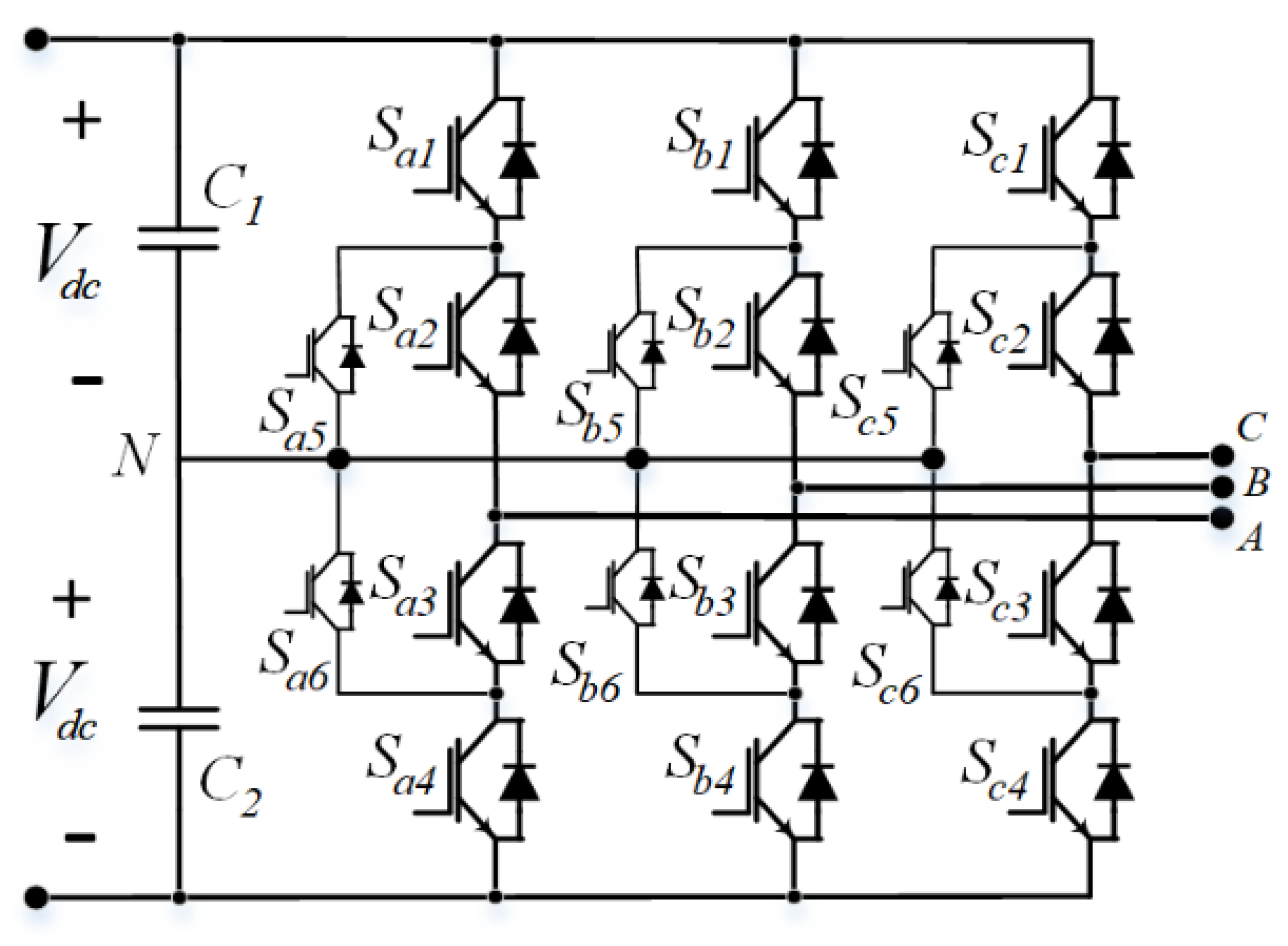
The dielectric strength of inverters is degraded by the influence of cosmic rays at flight level [16]. Accordingly, the inverter voltage is commonly selected to be around 1–2 kV. A full-bridge DC/AC pulse-width modulation inverter was investigated in [16]. Five-level stacked multi-cell DC/AC voltage source inverters were investigated in [16,17,18]. A single-phase switched-capacitor three-level inverter topology was tested in [17], as shown in Figure 3. Power modules with high current capabilities are preferred to achieve high-power delivery. Figure 4 shows a three-level active neutral point clamped (ANPC) inverter [13,14,15,16].
ANPC inverters have several features over conventional two-level voltage source inverters, such as lower semiconductor devices, which can be utilized because of the reduced conduction loss. Such reduced loss can decrease the average temperature components; hence, greater system reliability can be achieved. ANPC inverters allow lower voltage stresses for power switches compared with conventional two-level voltage source inverters [19]. Accordingly, ANPC inverters are expected to produce less EMI and reduced dv/dt for the same reason. All their switches are active switches, which allows flexibility in modulation and enables achieving multi-control objectives. Moreover, all the switches in these converters can be actively controlled to achieve bidirectional power flow.

2.2. Power Capability

A previous study, [16], reported a power level of 2.5 kW at a 20-kHz switching frequency for cryogenically-cooled converter prototypes. A 1-kW cooled power inverter was designed and tested at a 120-kHz switching frequency in [20,21]. A cryogenically-cooled inverter with 40-kW output power, 3-kHz output line frequency, and 140-kHz switching frequency was presented in [20]. Parallel and interleaving inverters provide increased power levels to fulfill aircraft loads (mainly motors [22]). Parallel inverters can be employed to reduce output harmonics as well. However, parallel inverters with common direct current (DC) and alternating current (AC) sides suffer from deleterious circulating currents [13,23].

2.3. Electromagnetic Interference

With CO2 reduction as an urgent global concern, the excellent physical properties of WBG devices are key to the energy saving of power conversion devices in different kinds of electrical systems. However, the adoption of WBG devices in power converters will severely increase the conducted and radiated EMI noise. This occurs because of the rapidly switching frequencies and faster switching speeds of WBG devices. Further, aircraft applications must meet DO-160 standards [24]. EMI filters may be needed for both DC and AC sides. However, EMI filters add size and weight burdens to aircraft systems. In this regard, three-level ANPC inverters have less EMI and reduced d v / d t [20]. Furthermore, interleaving inverters can be employed to reduce output harmonics. On another note, circulating current that may appear should be handled.
Because high d v / d t voltage charges parasitic capacitances, it is expected to generate high-frequency EMI problems [25]. Understanding this switching behavior in detail is therefore crucial not only in maximizing the efficiency of these converters but also in predicting the dynamic switching waveforms and the EMI implications of these higher switching frequencies. Thus, methods that accurately measure and compare these characteristics are required [26].

3. Power Switches Characterization at a Cryogenic Temperature

Solid-state device technologies are currently undergoing rapid advancement [27]. Bipolar junction transistors (BJTs), metal–oxide–semiconductor field-effect transistors (MOSFETs), and insulated gate bipolar transistors (IGBTs) are the three basic solid-state switches in the silicon transistor families. The BJT has a slow turn-off and a lower switching frequency. In contrast, by simply removing the gate signal and discharging the input capacitance, MOSFETs can be switched off rapidly. Meanwhile, IGBT merges BJT and MOSFET, where higher blocking voltages can be attained [25].
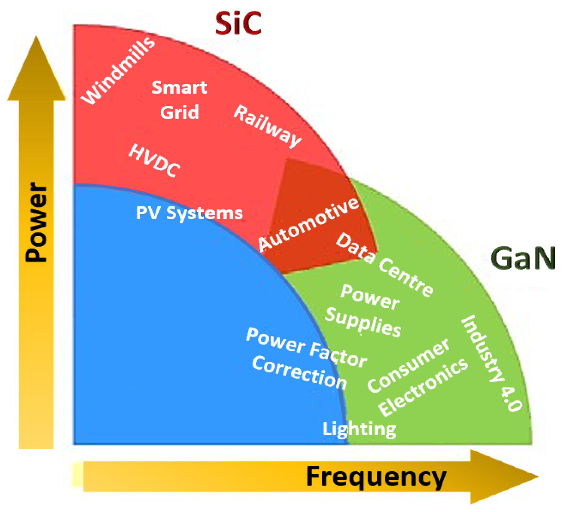
The energy bandgap of WBG devices is greater than that of conventional Si devices. This allows WBG devices to achieve better performance in terms of breakdown voltage, electron mobility, thermal conductivity, and switching speed [25]. Silicon carbide (SiC) and gallium nitride (GaN) are (in progress) promising WBG devices. They permit reduced sizes and increased efficiencies, operating frequencies, and temperatures. SiC power devices can efficiently work for high-temperature, high-power applications [27]. The cryogenic parametric characterization of silicon (Si) and SiC power MOSFETs and GaN power switches was conducted in [28]. From this study, GaN devices showed significant improvement at cryogenic temperatures. Conversely, the test results revealed that SiC devices cannot be utilized at cryogenic temperatures because of the significant increase in ON resistance. Figure 5 compares the applications of Si, SiC, and GaN power devices [27].
The ability to absorb heat at low temperatures is a prerequisite for cryogenic operations. This can be accomplished in two different ways: heat can be transferred to a fluid medium—usually, a gas refrigerated in a continuous cycle—through evaporation (or, in the case of a subcooled liquid, by temperature rise), or heat can be transferred to a fluid medium—usually, a gas refrigerated in a continuous cycle. Sometimes, combining both types of systems can be useful: a quantity of liquid, for example, can be employed as a refrigeration system’s buffer [29].
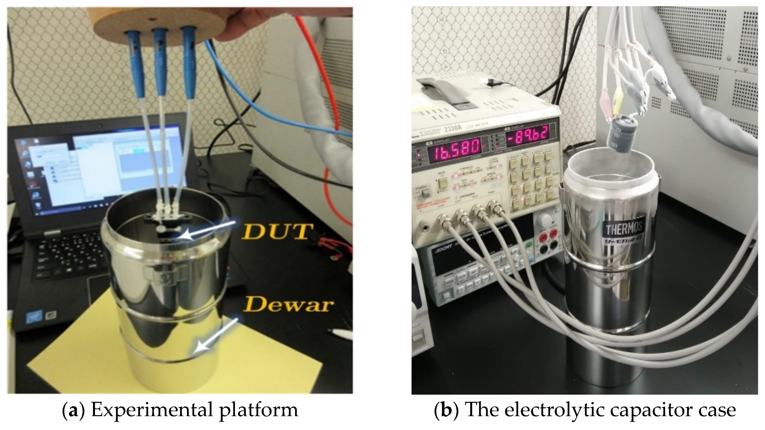
In this study, five commercially available power switches (Table 1) were tested under two conditions: (1) at room temperature (300 K), and (2) at a cryogenic temperature of 77 K, where the device under test (DUT) was cooled down by immersing it in liquid nitrogen filled in a Dewar. The measurement started after the DUT was kept in the liquid nitrogen for 30 min to ensure cooling. The four-terminal method was adopted to measure the ON-resistance of the device to eliminate the parasitic resistance of wiring cables and connectors. A discrete voltage source, current source, and voltage meter under the control of a personal computer were employed to perform the four-terminal measurement. The output and breakdown characteristics were measured using a curve tracer (Iwatsu CS-3000), as shown in Figure 6. Furthermore, the experimental platform with different case studies of the presented test setup is depicted in Figure 7.
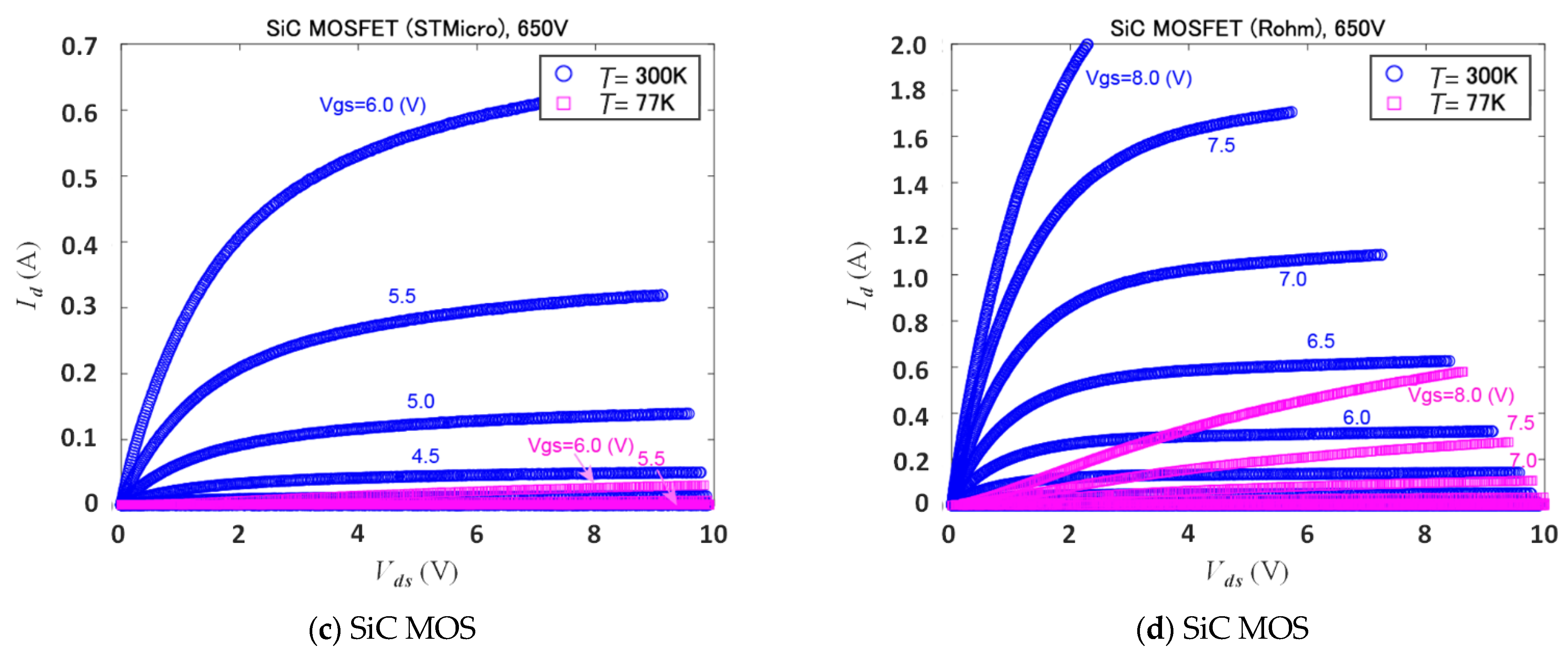
The summary of the characteristics of the power switches is shown in Table 2. Furthermore, the detailed characteristics are presented in Figure 8, Figure 9 and Figure 10. The results shown in Figure 8 represent the pulsed forward (drain current vs. drain to source voltage) characteristics of commercially available power switches at various gate-source voltages. These curves show that as the gate voltage increases, the drain current increases linearly to a certain level before remaining constant or saturated. In comparison to other switches, the Si-SJ MOSFET (Infineon) and GaN HEMT Cascode (Transphorm) switches had higher pulse current capabilities. Furthermore, at cryogenic temperature (77 K) very low current is exhibited for SiC MOSFETs from (STMicroelectronics) and (Rohm) compared to their corresponding characteristics at room temperature (300 K).
Furthermore, the results shown in Figure 9 reveal an excessive increase in the Ron of the SiC MOS switches. Accordingly, they are not suitable for operations at cryogenic temperatures. Conversely, the R on of both the Si SJ-MOS and GaN HEMT switches advantageously decreased at cryogenic temperatures, despite the decrease in breakdown voltage of the Si SJ-MOS switches. Moreover, the GaN HEMT switches demonstrated their exceptional performance at cryogenic temperatures in terms of high current capability and very low ON resistance.

4. Capacitors’ Performance at a Cryogenic Temperature

Because the performance of frequently used electronic devices at very low temperatures (i.e., cryogenic temperatures) is not commonly included in accompanying datasheets, evaluating such performance is of great interest. This unknown behavior may affect the energy density. Furthermore, capacitors are very essential components in most power electronics inverter/converter topologies employed in electric aircraft. Therefore, in this study, three commercially available capacitors were tested under two conditions: (1) at room temperature of 300 K, and (2) at a cryogenic temperature of 77 K (when immersed in liquefied nitrogen inside a stainless-steel Dewar). An LCR meter (model no. 2330A, NF Electronic Instrument) was used to measure the capacitor parameters at different frequencies (120 Hz, 1 kHz, 10 kHz, and 100 kHz) as follows.

4.1. Electrolytic Capacitor Case Study

An electrolytic capacitor was tested, as shown in Figure 7b. Several essential parameters were captured/measured and recorded under different frequencies at the specified temperatures of 300 K (room temperature) and 77 K (cryogenic temperature of nitrogen). The experimental results, recorded in Table 3, reveal that the capacitance decreased sharply because of the freezing of the chemical medium. Moreover, for the results at room temperature, it can be observed that the frequency did not significantly impact the capacitance value in the range from 120 Hz to 10 kHz. However, its value decreased to approximately half of its value at 100 kHz. The equivalent series resistance (ESR) dramatically decreased from 8.956 Ω at 1 kHz to 0.4672 Ω at 10 kHz. In addition, the measured dielectric dissipation factor revealed that at 300 K, its value increased greatly with increasing frequency, especially at 100 kHz.

4.2. Metalized Film Capacitor Case Study

A metalized film capacitor was tested, as shown in Figure 7c. Furthermore, Table 4 shows the electrolytic capacitor test results at different temperatures (300 K and 77 K) and frequencies (120 Hz, 1 kHz, 10 kHz, and 100 kHz). Several parameters were tabulated including capacitance value, ESR, and dielectric dissipation factor. The results show that the metalized film capacitor attained a stable performance, whereas the capacitance value slightly increased at cryogenic temperature. For instance, at 120 Hz frequency, the cryogenic temperature capacitance increased to 33.45 nF compared to a capacitance of 32.56 nF at room temperature.

4.3. Ceramic Capacitor Case Study

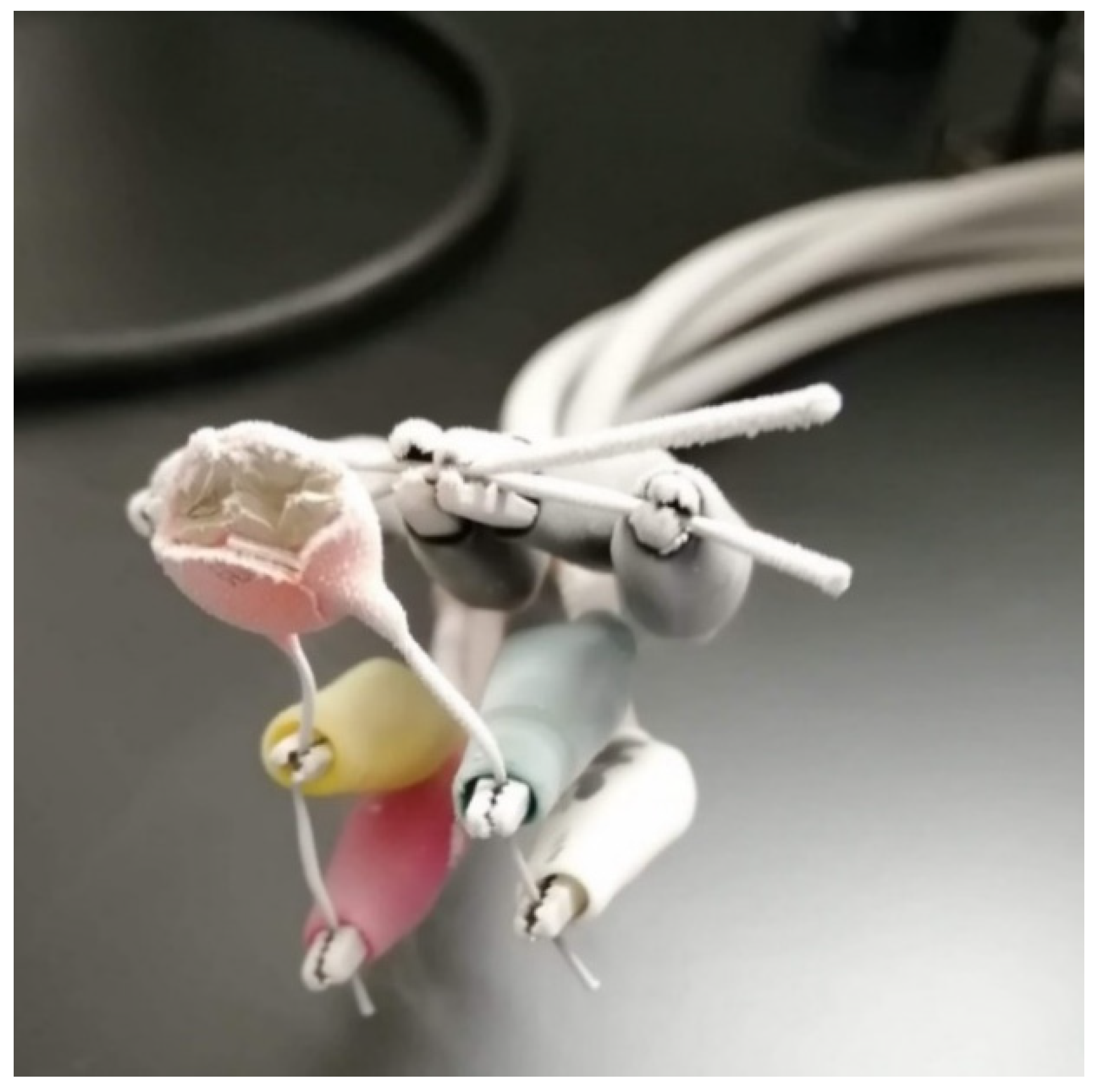
A ceramic capacitor was tested, as shown in Figure 7d. Furthermore, the experimental results, recorded in Table 5, show that the capacitor suffered from a mechanical failure (broken probably because of the different coefficients of thermal expansion/shrinkage of capacitor layers), as shown in Figure 11.
Comparative performance analysis of the three capacitors considered in this paper under the proposed operating conditions of frequencies and temperatures is depicted in Figure 12. This figure shows a significant decrease in the capacitance value in the electrolytic capacitor when the temperature is changed from 300 K to 77 K. Conversely, a slight increase in stable performance can be observed for the metalized film capacitor.

5. Conclusions

The characteristics of switching devices with different technologies used in power inverters employed in cryogenically-cooled electric aircraft applications were investigated in this study. The characterization tests conducted on the switching devices at cryogenic temperature revealed the unsuitability of SiC MOS switches in operations at cryogenic temperatures due to excessive increases in ON resistance compared to Si SJ-MOS and GaN HEMT switches. Moreover, the GaN HEMT switches demonstrated superior performance in cryogenic temperature operations in terms of breakdown voltage and ON resistance. Furthermore, the performances of three commercial types of capacitors (electrolytic, metalized film, and ceramic) were investigated experimentally at cryogenic temperatures. Such investigations demonstrated a stable performance of metalized film capacitors in contrast to the unsatisfactory operation of electrolytic and ceramic capacitors at a cryogenic temperature, in which the latter suffers from an unreliable operation and mechanical failure. Considering the above-addressed findings, new capacitor-less topologies should be developed for operation at cryogenic temperatures.

Author Contributions

Conceptualization, methodology, investigation, M.S.H., T.A., M.S. and G.M.D.; validation, M.S.H., T.A. and G.M.D.; writing—review and editing M.S.H., T.A. and G.M.D.; supervision M.S.H. and G.M.D.; project administration, M.S. All authors have read and agreed to the published version of the manuscript.

Funding

This research was funded by the New Energy and Industrial Technology Development Organization (NEDO), grant number JPNP15005.

Institutional Review Board Statement

The study was conducted according to the guidelines of the Declaration of Helsinki, and approved by the Ethics Committee of Kyushu University (General Regulations for Employment of National University Corporation Kyushu University No. 14 of 2009).

Informed Consent Statement

Informed consent was obtained from all subjects involved in the study.

Data Availability Statement

The data presented in this study are available upon request from the corresponding author.

Conflicts of Interest

The authors declare no conflict of interest.

References

  1. Citroni, R.; di Paolo, F.; Livreri, P. A Novel Energy Harvester for Powering Small UAVs: Performance Analysis, Model Validation and Flight Results. Sensors 2019, 19, 1771. [Google Scholar] [CrossRef] [Green Version]
  2. Citroni, R.; Leggieri, A.; Passi, D.; di Paolo, F.; di Carlo, A. Nano Energy Harvesting with Plasmonic Nano-Antennas: A review of MID-IR Rectenna and Application. AEM 2017, 6, 1–13. [Google Scholar] [CrossRef] [Green Version]
  3. Sarlioglu, B.; Morris, T.C. More Electric Aircraft: Review, Challenges, and Opportunities for Commercial Transport Aircraft. IEEE Trans. Transp. Electrif. 2015, 1, 54–64. [Google Scholar] [CrossRef]
  4. Jha, A.R. Cryogenic Technology and Applications; Butterworth-Heinemann: Oxford, UK, 2006; pp. 1–23. ISBN 9780750678872. [Google Scholar] [CrossRef]
  5. Zhang, Z.; Timms, C.; Tang, J.; Chen, R.; Sangid, J.; Wang, F.; Tolbert, L.M.; Blalock, B.J.; Costinett, D.J. Characterization of high-voltage high-speed switching power semiconductors for high frequency cryogenically-cooled application. In Proceedings of the 2017 IEEE Applied Power Electronics Conference and Exposition (APEC), Tampa, FL, USA, 26–30 March 2017; pp. 1964–1969. [Google Scholar] [CrossRef]
  6. Gui, H.; Chen, R.; Niu, J.; Zhang, Z.; Tolbert, L.M.; Wang, F.F.; Blalock, B.J.; Costinett, D.; Choi, B.B. Review of Power Electronics Components at Cryogenic Temperatures. IEEE Trans. Power Electron. 2020, 35, 5144–5156. [Google Scholar] [CrossRef] [PubMed]
  7. Rajashekara, K.; Akin, B. A Review of Cryogenic Power Electronics—Status and Applications. In Proceedings of the International Electric Machines & Drives Conference, Chicago, IL, USA, 12–15 May 2013; Volume 2013, pp. 899–904. [Google Scholar] [CrossRef]
  8. Haldar, P.; Ye, H.; Efstathiadis, H.; Raynolds, J.; Hennessy, M.; Mueller, O.; Mueller, E. Improving Performance of Cryogenic Power Electronics. IEEE Trans. Appl. Supercond. 2005, 15, 2370–2375. [Google Scholar] [CrossRef]
  9. Rajashekara, K.; Akin, B. Cryogenic Power Conversion Systems: The Next Step in the Evolution of Power Electronics Technology. IEEE Electrif. Mag. 2013, 1, 64–73. [Google Scholar] [CrossRef]
  10. Dogmus, E.; Kabouche, R.; Lepilliet, S.; Linge, A.; Zegaoui, M.; Ben-Ammar, H.; Chauvat, M.-P.; Ruterana, P.; Gamarra, P.; Lacam, C.; et al. InAlGaN/GaN HEMTs at Cryogenic Temperatures. Electronics 2016, 5, 31. [Google Scholar] [CrossRef] [Green Version]
  11. Singh, R.; Baliga, B.J. Cryogenic Operation of Silicon Power Devices; Kluwer Academic Publishers: Norwell, MA, USA, 1998. [Google Scholar]
  12. Gira, G.; Ferraro, E.; Borgarino, M. On the VCO/Frequency Divider Interface in Cryogenic CMOS PLL for Quantum Computing Applications. Electronics 2021, 10, 2404. [Google Scholar] [CrossRef]
  13. Wang, F.; Chen, R.; Gui, H.; Niu, J.; Tolbert, L.; Costinett, D.; Blalock, B.; Liu, S.; Hull, J.; Williams, J.; et al. MW-Class Cryogenically-Cooled Inverter for Electric-Aircraft Applications. In Proceedings of the AIAA/IEEE Electric Aircraft Technologies Symposium (EATS), Indianapolis, IN, USA, 22–24 August 2019; Volume 2019, pp. 1–9. [Google Scholar] [CrossRef]
  14. Hou, H.; Yang, J.; Liu, G.; Liu, J.; Abbas, M.; Hussain, S.; Shao, H.; Qiao, G.; Ghfar, A.; Ouladsmane, M.; et al. Designing Optically & Utilization of Thermopile Chip with Resonant Cavity Absorber Structure as IR Absorber. Coatings 2021, 11, 302. [Google Scholar] [CrossRef]
  15. Feng, Y.J.; Zeng, L.; Chen, Y.; Liu, X.D.; Li, T.; Xie, Q.; Chen, X.Y. Hardware Design and Test of a Cryogenic Boost Chopper under 77 K. In Proceedings of the 2018 in IEEE International Conference on Applied Superconductivity and Electromagnetic Devices (ASEMD), Tianjin, China, 15–18 April 2018; pp. 1–2. [Google Scholar] [CrossRef]
  16. Filipenko, M.; Biser, S.; Boll, M.; Corduan, M.; Noe, M.; Rostek, P. Comparative Analysis and Optimization of Technical and Weight Parameters of Turbo-electric Propulsion Systems. Aerospace 2020, 7, 107. [Google Scholar] [CrossRef]
  17. Mueller, O.M.; Herd, K.G. Ultra-High Efficiency Power Conversion Using Cryogenic MOSFETs and HT-Superconductors. In Proceedings of the IEEE Power Electronics Specialist Conference, PESC, Seattle, WA, USA, 20–24 June 1993; pp. 772–778. [Google Scholar] [CrossRef]
  18. Boll, M.; Corduan, M.; Biser, S.; Filipenko, M.; Pham, Q.H.; Schlachter, S.; Rostek, P.; Noe, M. A Holistic System Approach for Short Range Passenger Aircraft with Cryogenic Propulsion System. Supercond. Sci. Technol. 2020, 33, 14. [Google Scholar] [CrossRef]
  19. Gui, H.; Zhang, Z.; Chen, R.; Ren, R.; Niu, J.; Li, H.; Dong, Z.; Timms, C.; Wang, F.; Tolbert, L.M.; et al. Development of High-Power High Switching Frequency Cryogenically Cooled Inverter for Aircraft Applications. IEEE Trans. Power Electron. 2020, 35, 5670–5682. [Google Scholar] [CrossRef]
  20. Barth, C.; Colmenares, J.; Foulkes, T.; Coulson, K.; Sotelo, J.; Modeer, T.; Miljkovic, N.; Pilawa-Podgurski, R.C. Experimental Evaluation of a 1 kW, Single-Phase, 3-Level Gallium Nitride Inverter in Extreme Cold Environment. In Proceedings of the IEEE Applied Power Electronics Conference and Exposition (APEC), Tampa, FL, USA, 26–30 March 2017; Volume 2017, pp. 717–723. [Google Scholar] [CrossRef]
  21. Barth, C.B.; Foulkes, T.; Azofeifa, O.; Colmenares, J.; Coulson, K.; Miljkovic, N.; Pilawa-Podgurski, R.C.N. Design, Operation, and Loss Characterization of a 1-kW GaN-Based Three-Level Converter at Cryogenic Temperatures. IEEE Trans. Power Electron. 2020, 35, 12040–12052. [Google Scholar] [CrossRef]
  22. Corduan, M.; Boll, M.; Bause, R.; Oomen, M.P.; Filipenko, M.; Noe, M. Topology Comparison of Superconducting AC Machines for Hybrid Electric Aircraft. IEEE Trans. Appl. Supercond. 2020, 30, 1–10. [Google Scholar] [CrossRef] [Green Version]
  23. Hassan, M.S.; Abdelhakim, A.; Shoyama, M.; Imaoka, J.; Dousoky, G.M. Parallel Operation of Split-Source Inverters for PV Systems: Analysis and Modulation for Circulating Current and EMI Noise Reduction. IEEE Trans. Power Electron. 2021, 36, 9547–9564. [Google Scholar] [CrossRef]
  24. Radio Technical Commission for Aeronautics (RTCA). Environmental Conditions and Test Procedures for Airborne Equipment; D.O.-160G; Radio Technical Commission for Aeronautics (RTCA): Washington, DC, USA, 2010. [Google Scholar]
  25. Lee, T.; Kim, H.; Lee, N.; Chin, T.; Bu, H.; Cho, Y. Performance Evaluation of GaN FET-Based Matrix Converters with dv/dt Filters for Variable Frequency Drive Applications. J. Power Electron. 2020, 20, 844–853. [Google Scholar] [CrossRef]
  26. Wilson, P.R. Advanced Aircraft Power Electronics Systems—The Impact of Simulation, Standards and Wide Band-Gap Devices. CES Trans. Electr. Mach. Syst. 2017, 1, 72–82. [Google Scholar] [CrossRef]
  27. Raciti, A.; Rizzo, S.A.; Salerno, N.; Susinni, G.; Buccella, C.; Cecati, C.; Tinari, M. State of the Art and Emerging Solid-State Power Devices in the Perspective of More Electric Aircraft. In Proceedings of the AEIT International Annual Conference, Bari, Italy, 3–5 October 2018; Volume 2018, pp. 1–6. [Google Scholar] [CrossRef]
  28. Gonzalez, M.C.; Kohlman, L.W.; Trunek, A.J. Cryogenic Parametric Characterization of Gallium Nitride Switches; National Aeronautics and Space Administration, Glenn Research Center: Cleveland, OH, USA, 2018.
  29. Croft, A.J.; Fickett, F.R. Cryogenic Laboratory Equipment; American Institute of Physics: College Park, MD, USA, 1971; Volume 24, pp. 55–56. [Google Scholar] [CrossRef] [Green Version]
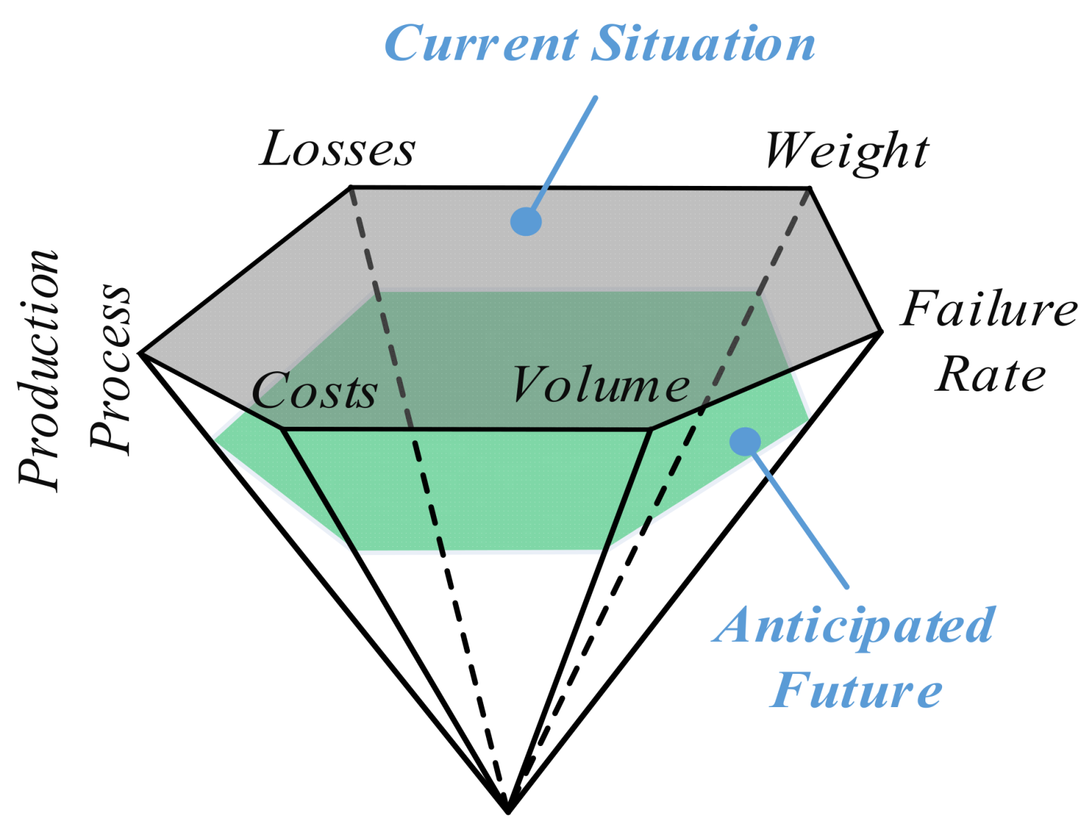
Figure 1. Anticipated power electronics objectives.
Electronics 11 00826 g001
Figure 2. Degrees of freedom for performance improvement.
Electronics 11 00826 g002
Figure 3. Three-level switched-capacitor inverter topology [11].
Electronics 11 00826 g003
Figure 4. Three-level active neutral point clamped (ANPC) inverter topology.
Electronics 11 00826 g004
Figure 5. Comparison of the applications of Si, SiC, and GaN power devices [27].
Electronics 11 00826 g005
Figure 6. A schematic diagram of the experimental test setup.
Electronics 11 00826 g006
Figure 7. The experimental test setup.
Electronics 11 00826 g007aElectronics 11 00826 g007b
Figure 8. The experimentally measured drain characteristics at 300 K and 77 K.
Electronics 11 00826 g008aElectronics 11 00826 g008b
Figure 9. The experimentally measured ON resistance, Ron, at 300 K and 77 K: (a) all the tested switches; (b) zoomed results for the Si SJ-MOS and GaN HEMT switches.
Electronics 11 00826 g009
Figure 10. Experimentally-measured breakdown characteristics at 300 K and 77 K.
Electronics 11 00826 g010
Figure 11. Mechanical failure (breakage) in the ceramic capacitor during the experimental testing.
Electronics 11 00826 g011
Figure 12. Comparative analysis of the capacitance values for specified types of capacitors under different frequencies at room and cryogenic temperatures.
Electronics 11 00826 g012
Table 1. List of tested power switches.
DescriptionSupplierCatalog No.Remarks
Si SJ-MOS, 600 V, 21 AInfineonIPW60R105CFD7
Si SJ-MOS, 900 V, 15 AInfineonIPW90R340C3
SiC MOS, 650 V, 70 ARohmSCT3030AL-E
SiC MOS, 650 V, 45 ASTMicroelectronicsSCTWA35N65G2V
GaN HEMT, 650 V, 36 ATransphormTP65H050WSCascode connection with Si MOSFET
Table 2. Summary of the characteristics of power switches.
Device Spec. (Vendor)Si SJ-MOS *1SiC MOSGaN HEMT *2
600 V, 21 A (Infineon)900 V, 15 A
(Infineon)
650 V, 70 A (Rohm)650 V, 45 A (STMicroelectronics)650 V, 36 A (Transphorm)
Breakdown
voltage (BV)
300 K634 V993 V1182 V771 V>1400 V
77 K482 V703 V1219 V654 V1374 V
R on @ V gs = 15 V, I d = 1 A300 K85 mΩ265 mΩ49 mΩ69 mΩ39 mΩ
77 K57 mΩ40 mΩ1000 mΩ3190 mΩ17 mΩ
CommentsBV falls down at 77 K; well agrees with device
simulation
BV keeps above 600 V at 77 KDramatic increase in R on at 77 KDramatic increase in R on at 77 KThe breakdown mechanism is different from those
of the others
*1 Super Junction MOSFET. *2 Cascode-connected HEMT with Si MOSFET.
Table 3. The electrolytic capacitor test results at different temperatures and frequencies.
Frequency120 Hz1 kHz10 kHz100 kHz
Temperature (K)30077300773007730077
C (μF)88.170.01623386.570.01617182.040.01614844.950.016134
ESR (Ω)OF *1OF8.956OF0.4672OF0.3453OF
Ɵ (°)−87.83−89.92−77.96−89.95−28.02−89.95−5.93−89.98
D *20.0380.00110.21080.00011.86120.00089.5990.0004
*1 Overflow. *2 Dielectric dissipation factor.
Table 4. The electrolytic capacitor test results at different temperatures and frequencies.
Frequency120 Hz1 kHz10 kHz100 kHz
Temperature (K)30077300773007730077
C (nF)32.5633.4532.5633.4532.5533.432.5633.44
ESR (Ω)OFOFOFOFOFOFOFOF
Ɵ (°)−90−90−89.99−90−89.99−90−90.03−90.04
D000.000100.00020−0.0005−0.02
Table 5. The ceramic capacitor test results.
Frequency120 Hz1 kHz10 kHz100 kHz
Temperature (K)30077300773007730077
C (nF)1.84960.02841.84330.027361.83520.02651.8280.02574
ESR (Ω)OFOFOFOFOFOFOFOF
Ɵ (°)−89.56−88.78−89.74−88.6−89.84−88.71−89.78−88.37
D0.00710.020.0450.0220.0280.02250.00380.029
Publisher’s Note: MDPI stays neutral with regard to jurisdictional claims in published maps and institutional affiliations.