Article

Dielectric-Loaded Miniaturized Cavity Bandpass Filter with Improved Power Capacity

1
School of Physics and Electronic Information, Gannan Normal University, Ganzhou 341000, China
2
Research Center for Rare Earth Materials and Applications, Gannan Normal University, Ganzhou 341000, China
*
Author to whom correspondence should be addressed.
Electronics 2022, 11(9), 1441; https://doi.org/10.3390/electronics11091441
Submission received: 1 April 2022 / Revised: 26 April 2022 / Accepted: 26 April 2022 / Published: 29 April 2022

Abstract

:
A novel design method of dielectric-loaded miniaturized cavity bandpass filter is presented in this paper. The proposed cavity resonator is filled with dielectric material to improve power capacity, while realizing the miniaturization of the filter. To validate our proposal, a bandpass filter with a center frequency of 1475 MHz and bandwidth of 90 MHz is designed, fabricated, and measured. The measured insertion loss is ≤0.49 dB and return loss is ≥20 dB in 1430 MHz~1520 MHz. The measured upper stopband rejection is greater than 48.5 dB in 1575 MHz~2700 MHz. The measured results are in good agreement with the simulation, which verifies the effectiveness and practicability of the method. The metal cavity bandpass filter, filled with dielectric material, is reduced by 25% in the thickness direction and its power capacity is increased by 45.8%.

1. Introduction

As an important passive device, filters are widely used in 5G wireless communication systems, satellite navigation, radar detection, electronic countermeasures and other fields [1,2,3,4,5,6]. Filter performance is often directly related to the performance of the whole RF transceiver system. With the development and application of modern wireless communication technology, limited spectrum resources are becoming increasingly crowded and precious with higher requirements for high performance; therefore, the miniaturization [7,8,9,10,11,12] and high power [13,14,15,16] of filters are put forward. The main function of bandpass filters is to allow useful signals to pass through with low loss, while suppressing useless stray signals. Miniaturization has always been one of the hot directions of filters. Based on the research status of filters [17], the current miniaturization technologies of cavity filters mainly include the following: (1) loading technology [18,19,20], such as resonator capacitor loading, lumped element loading and high permittivity ceramic material loading, etc.; (2) multi-mode resonator technology [21,22,23,24,25] that, in a resonant cavity, motivates two or more resonant modes simultaneously; (3) spiral resonator [26], short circuit branch [27], slow wave structure [8] and other technologies are used to realize the miniaturization of filters. Generally, as the size of filter decreases, the power capacity of the filter will also decrease. Therefore, it is very important to consider power capacity [28] while considering the miniaturization of filters.
First, by introducing dielectric material to fill the metal coaxial resonator, the loading capacitance value is increased, the miniaturization of the filter is realized, and the maximum breakdown electric field of resonator is also increased. Second, a Generalized Chebyshev filter is designed and fabricated. Third, a theoretical analysis of the power capacity is given. Finally, the measured results are listed.

2. Dielectric-Loaded Metal Resonator

Capacitance loading is one of the methods used to miniaturize a metal cavity filter, especially in low frequency bands where the corresponding size of the resonator is larger. The usual method makes a resonator with a loaded resonant plate structure and the loaded plate and top surface of the resonator forms a large capacitance, so as to achieve the purpose of miniaturization. The capacitance effect can be analyzed using the parallel plate capacitor formula. A parallel plate capacitor is shown in Figure 1.
C = ε r ε 0 S 4 π k d
It should be noted that ε r is the relative permittivity, and ε r of air is 1.0. According to Equation (1) of the parallel plate capacitor, the value of capacitance C increases when the relative permittivity increases. For the resonator, the larger the capacitance between the loaded plate and top surface of resonator, the lower the resonant frequency. Therefore, if the size of the resonator is kept unchanged and the air between the surface of the resonator plate and top surface of the resonator is replaced by dielectric materials with higher permittivity, the resonant frequency can be lower, so as to achieve the purpose of miniaturization. As shown in Figure 2b, the dielectric-loaded resonator has a single cavity size of φ16 × H13 mm. Its single cavity resonant frequency is shown in Table 1, using dielectric materials with different relative permittivity. As can be observed from Table 1, the larger the permittivity of the loading medium, the lower the resonant frequency of resonator. The ceramic materials with high permittivity can achieve lower resonant frequency without changing the size of the resonant cavity. Therefore, we can achieve the goal of filter miniaturization by loading the metal resonator with dielectric material. From the analysis of the dielectric-loaded resonator, we can use a dielectric-loaded resonator to miniaturize a cavity filter. ir="LTR">1008.4

3. Design of Generalized Chebyshev Filter

The generalized Chebyshev filter response can be set to the pole position in the stopband arbitrarily and is more flexible than the ordinary Chebyshev filter response. The response of the generalized Chebyshev filter can produce isoripple characteristics in the passband, and its characteristic response curve is similar to that of the elliptic function. The amplitude of its transmission function can be expressed as Equation (2), ch(x) represents the hyperbolic cosine function in Equations (3) and (4) and xi is the intermediate variable in Equation (5).
s 21 j ω 2 = 1 1 + ε 2 C N 2 ω
C N ω = ch i = 1 N ch 1 x i
ch x = e x + e x 2  
x i = ω 1 / ω p i 1 ω / ω p i
A fourth-order, two-zeros cross-coupled bandpass filter is designed by using dielectric-loaded metal resonators. The topology is shown in Figure 3.
After comprehensive theoretical evaluation of a generalized Chebyshev filter [29,30,31,32,33,34,35,36,37], it can be concluded that the delay of the group is 4.63 ns, and the two transmission zeros are 1584 MHz and 1643 MHz, respectively. The coupling matrix is shown in Figure 4. The corresponding circuit model and filter response suggested in the AWR circuit software are shown in Figure 5.
If the conventional capacitive-loaded metal resonator in Figure 2a is adopted, the single cavity size is 17.5 × 17.5 × 16.3 mm3 and the resonance frequency of 1475 MHz is achieved. In addition, for the dielectric plate material using Telfon ( ε r = 2.1 ), the diameter of resonator base is φ4 mm, the size of the single cavity is 17.5 × 17.5 × 13 mm3, the resonance frequency of 1475 MHz is achieved and the resonator height is reduced by about 25%. A schematic diagram of the metal resonant disk and dielectric disk is shown in Figure 6. The structure of the metal resonant plate and dielectric plate is shown in Figure 7.
After co-simulation optimization of AWR and HFSS software, the height of the connector is 5.1 mm, and the height of each resonator is 6.87 mm, 6.90 mm, 6.82 mm and 6.80 mm, respectively. The simulation results are shown in Figure 5, where the return loss is 22 dB and the suppression of out-of-band is ≥45 dB at 1575 MHz~2700 MHz.

4. Theory of Filter Power Capacity

In a resonant cavity, the distribution of the electromagnetic field is related to the structure of the cavity. If the electric field distribution in the cavity is expressed as Equation (6), Emax is the electric field amplitude of the maximum electric field point in the cavity, f x , y , z is the distribution function of electric field in the cavity and its maximum amplitude equals 1.0.
E = E Max f x , y , z
f x , y , z Max = 1
The value of EMax is related to the excitation power of the cavity and the distribution function f x , y , z is independent of the excitation power. In the cavity, the energy storage of the electric field is listed as Equation (8).
W Max = ε 0 2 V   E · E d V = E Max 2 · ε 0 2 V   f x , y , z · f x , y , z d V = 1 ζ 2 E Max 2  
ζ = E Max W Max = 1 ε 0 2 V   f   x , y , z · f x , y , z d V
After the cavity structure is fixed, ζ is a constant in Equation (9), which indicates that the square of the maximum electric field has a linear relationship with the energy storage. Equation (10) can be used to calculate the proportionality coefficient between the excitation power of the filter port and the maximum energy storage of the resonant cavity.
η = W Max / P i n
Combining Equations (9) and (10), Equation (11) can be obtained.
E Max = ζ · η · P i n
If the maximum electric field (EMax) in the resonator is less than the breakdown field Ep, the filter is safe. Conversely, if the maximum electric field (Emax) in the resonant cavity is greater than the air breakdown field Ep, the filter will be broken down. When EMax = Ep, the power capacity of the filter can be obtained from Equation (12).
P Max = 1 η E p ζ 2
Combined with the above filter power capacity calculation theory, the power capacities of the two kinds of resonators are compared and analyzed in CST software, respectively, according to the two kinds of resonator structures, as shown in Figure 2, with the same resonator cavity size and resonant frequency.
As can be observed from the single-cavity simulation results in Figure 8, the resonant frequencies of the metal coaxial resonator and the dielectric-loaded resonator are both around 1375 MHz, and the values of ζ   in the two resonators obtained from the simulation are ζ 1 = 2.461 e 9 V/m and ζ 2 = 2.038 e 9 V/m. According to the filter power capacity calculation formula (12), the power capacity ratio of the two resonators can be obtained. In other words, the power capacity of the dielectric-loaded resonator is improved by 45.8%, compared with that of the common metal coaxial resonator.

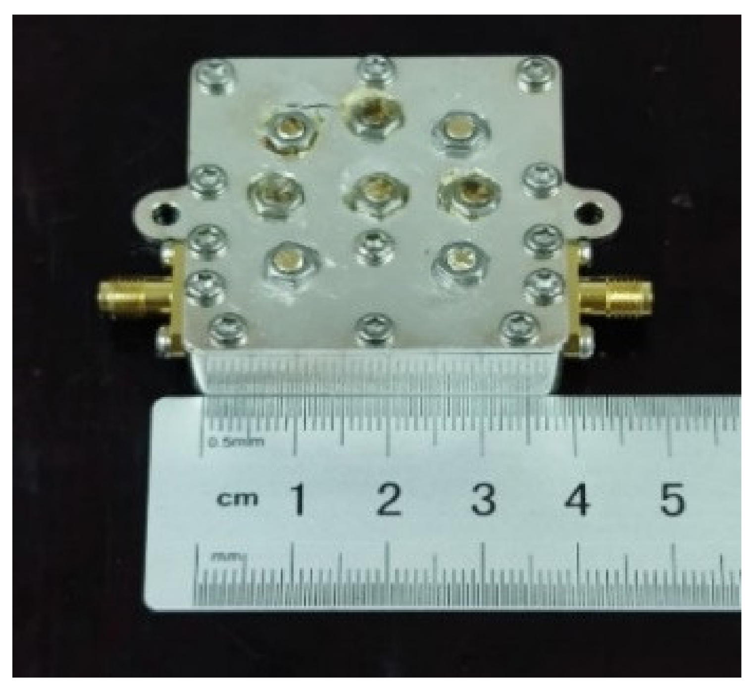
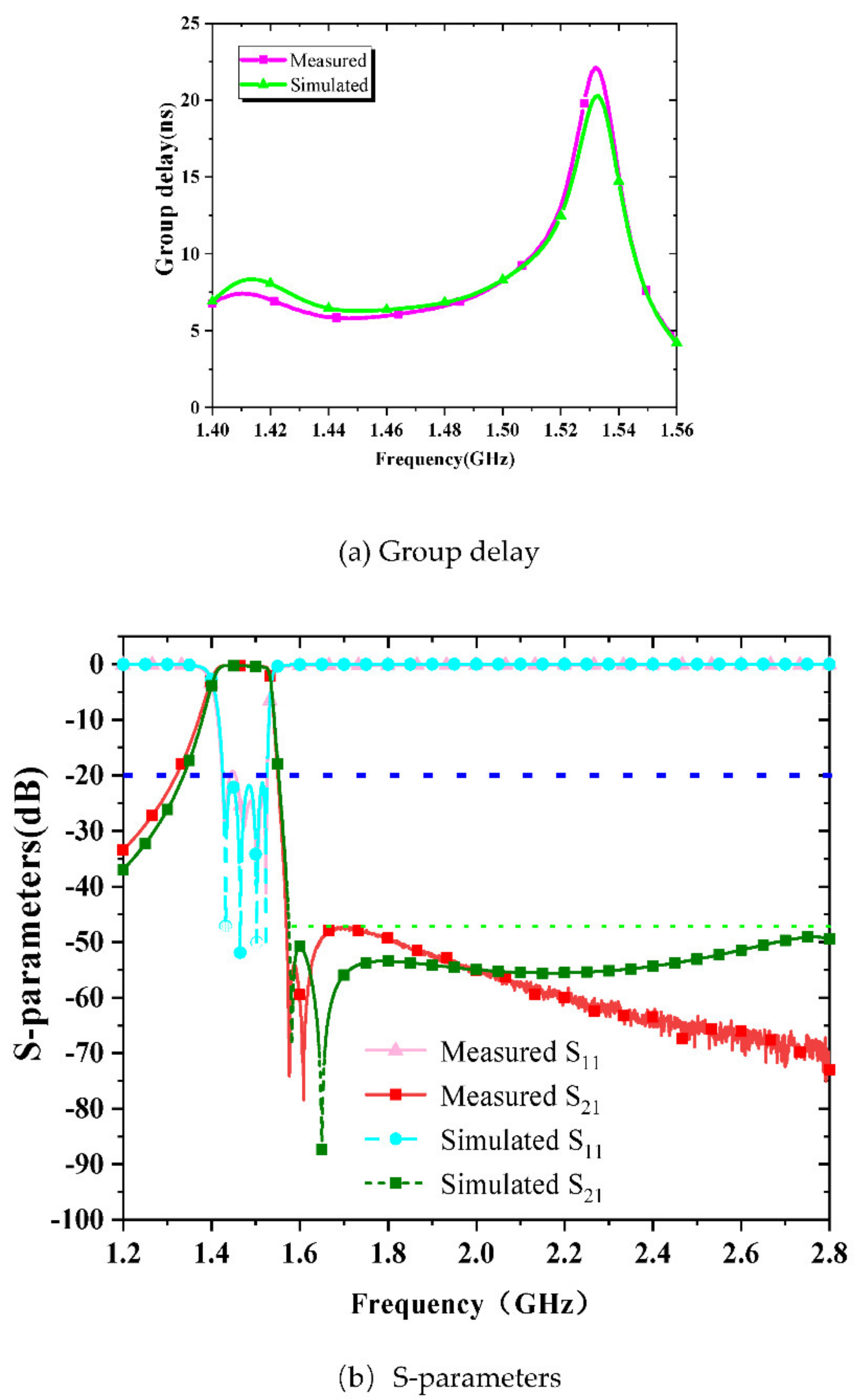
5. Experimental Results of Dielectric-Loaded Miniaturized Cavity Bandpass Filter

The 1475 MHz dielectric-loaded bandpass filter was fabricated and measured. Figure 9 is a photograph of the fabricated bandpass filter. Figure 10 is the measured results with Agilent Technologies PNA network analyzer (N5222A). Within the passband of 1430 MHz~1520 MHz, the return loss is ≥20 dB. The insertion loss of 1430 MHz and 1520 MHz is 0.27 dB and 0.49 dB, respectively. In 1575 MHz~2700 MHz, the suppression of out-of-band is greater than or equal to 48.5 dB. The measured results are in good agreement with the simulation.
Table 2 summarizes the performance comparison between the related work and the proposed filter. We can conclude from this table that the contributions of this work are not only its new design method, but also its good filter performance.

6. Conclusions

In this paper, a novel dielectric-loaded miniaturized cavity bandpass filter is presented. The filter has a miniaturized size and higher power capacity. By introducing a dielectric-loaded resonator structure on the basis of the conventional capacitive-loaded metal resonator, the miniaturization of the filter was realized. The measured results are in good agreement with the simulation, which verifies the validity and practicability of the miniaturization method with the dielectric-loaded resonator. Compared with the usual metal-cavity coaxial bandpass filter, the metal cavity bandpass filter loaded with dielectric material (Telfon) reduces by 25% in the thickness direction under the same electrical specifications and power capacity can be increased by 45.8%. The measured insertion loss is ≤0.49 dB and return loss is ≥20 dB in 1430 MHz~1520 MHz. The measured upper stopband rejection is greater than 48.5 dB in 1575 MHz~2700 MHz. Finally, the miniaturized advantage and high-power capacity of the filter makes it suitable for wireless communication.

Author Contributions

Conceptualization, C.R.; methodology, C.R.; software, Y.X.; validation, Y.Z.; formal analysis, C.R.; investigation, Y.X.; resources, C.R.; data curation, Y.X.; writing—original draft preparation, C.R.; writing—review and editing, C.R.; visualization, Y.X.; supervision, Y.X.; project administration, C.R.; funding acquisition, C.R. All authors have read and agreed to the published version of the manuscript.

Funding

This research was funded by [Science and Technology Project of the Jiangxi Provincial Department of Education] grant number [GJJ190750], [Scientific Research Base Project of Gannan Normal University] grant number [2020KY08] and [College Students Innovation and Entrepreneurship Training Program of Jiangxi Province] grant number [S202110418009] and [CX210048].

Data Availability Statement

Please refer to suggested Data.

Conflicts of Interest

The authors declare no conflict of interest.

References

  1. Laplanche, E.; Delhote, N.; Périgaud, A.; Tantot, O.; Verdeyme, S.; Bila, S.; Pacaud, D.; Carpentier, L. Tunable Filtering Devices in Satellite Payloads: A Review of Recent Advanced Fabrication Technologies and Designs of Tunable Cavity Filters and Multiplexers Using Mechanical Actuation. IEEE Microw. Mag. 2020, 21, 69–83. [Google Scholar] [CrossRef]
  2. Rong, C.; Xu, Y.; Xia, M.; Luo, Y.; Ou, R. Broadband class E GaN power amplifier design in S band with low-pass match. In Proceedings of the 2014 IEEE International Conference on Communiction Problem-Solving, Beijing, China, 5–7 December 2014; pp. 372–375. [Google Scholar] [CrossRef]
  3. Maity, S.; Ghosal, R.; Gupta, B. Modal Charts of Cylindrical Dielectric Resonators [Application Notes]. IEEE Microw. Mag. 2021, 23, 54–71. [Google Scholar] [CrossRef]
  4. Shahid, I.; Thalakotuna, D.; Karmokar, D.K.; Mahon, S.J.; Heimlich, M. Periodic Structures for Reconfigurable Filter Design: A Comprehensive Review. IEEE Microw. Mag. 2021, 22, 38–51. [Google Scholar] [CrossRef]
  5. Doumanis, E.; Goussetis, G.; Vuorio, J.; Hautio, K.; Amper, O.; Kuusmik, E.; Pallonen, J. Tunable Filters for Agile 5G New Radio Base Transceiver Stations [Application Notes]. IEEE Microw. Mag. 2021, 22, 26–37. [Google Scholar] [CrossRef]
  6. Mao, C.X.; Zhang, Y.; Zhang, X.Y.; Xiao, P.; Wang, Y.; Gao, S. Filtering Antennas: Design Methods and Recent Developments. IEEE Microw. Mag. 2021, 22, 52–63. [Google Scholar] [CrossRef]
  7. Widaa, A.; Höft, M. Miniaturized Dual-Band Dual-Mode TM-Mode Dielectric Filter in Planar Configuration. IEEE J. Microw. 2022, 2, 326–336. [Google Scholar] [CrossRef]
  8. Deng, J.Y.; Yuan, D.D.; Yin, J.Y.; Sun, D.; Guo, L.X.; Ma, X.H.; Hao, Y. Ultracompact Bandpass Filter Based on Slow Wave Substrate Integrated Groove Gap Waveguide. IEEE Trans. Microw. Theory Tech. 2022, 70, 1211–1220. [Google Scholar] [CrossRef]
  9. Zhao, D.; Lin, F.; Sun, H.; Zhang, X.Y. A Miniaturized Dual-Band SIW Filtering Antenna with Improved Out-of-Band Suppression. IEEE Trans. Antennas Propag. 2022, 70, 126–134. [Google Scholar] [CrossRef]
  10. Zhang, Z.; Zhang, G.; Liu, Z.; Tang, W.; Yang, J. Compact Balanced Bandpass Filter Based on Equilateral Triangular Patch Resonator. IEEE Trans. Circuits Syst. II Express Briefs 2022, 69, 90–93. [Google Scholar] [CrossRef]
  11. Feng, T.; Ma, K.; Wang, Y. A Miniaturized Bandpass Filtering Power Divider Using Quasi-Lumped Elements. IEEE Trans. Circuits Syst. II Express Briefs 2022, 69, 70–74. [Google Scholar] [CrossRef]
  12. Qin, T.; Lin, X.Q.; Fan, Y.L. Analysis, Design, and Implementation of Miniaturized Multimode Waveguide Filters Based on Epsilon-Near-Zero Channel Concept. IEEE Trans. Microw. Theory Tech. 2021, 69, 3598–3606. [Google Scholar] [CrossRef]
  13. Sekiya, N.; Kobayashi, S. Compact, Low Loss, and High Power Handling HTS Dual-Mode Double-Strip Resonator Filter with New Feeding Structure. IEEE Trans. Appl. Supercond. 2019, 29, 1500804. [Google Scholar] [CrossRef]
  14. Sekiya, N. Design of Compact and High-Power HTS Double-Strip Dual-Mode Patch Resonator Filter for Transmit Filter Applications. IEEE Trans. Appl. Supercond. 2017, 27, 1501804. [Google Scholar] [CrossRef]
  15. Setsune, K.; Enokihara, A. Elliptic-disc filters of high-T/sub c/superconducting films for power-handling capability over 100 W. IEEE Trans. Microw. Theory Tech. 2000, 48, 1256–1264. [Google Scholar] [CrossRef]
  16. Shen, Y.; Zhang, R.; Vetury, R.; Shealy, J. 40.6 Watt, High Power 3.55 GHz Single Crystal XBAW RF Filters for 5G Infrastructure Applications. In Proceedings of the 2020 IEEE International Ultrasonics Symposium (IUS), Las Vegas, NV, USA, 7–11 September 2020; pp. 1–3. [Google Scholar] [CrossRef]
  17. Free, C.E.; Aitchison, C.S. “RF Filters”, RF and Microwave Circuit Design: Theory and Applications; Wiley: Hoboken, NJ, USA, 2022; pp. 209–237. [Google Scholar] [CrossRef]
  18. Shan, Q.; Chen, C.; Wu, W. Design of an UWB bandpass filter with a notched band using asymmetric loading stubs. In Proceedings of the 2016 IEEE International Conference on Microwave and Millimeter Wave Technology (ICMMT), Beijing, China, 5–8 June 2016; pp. 410–412. [Google Scholar] [CrossRef]
  19. Zhou, P.; Shi, Y.; Tang, W. Multi-Mode and Ultra-Wideband Common-Mode Filter Based on Asymmetric Short-Stub Loaded Resonator. In Proceedings of the 2019 IEEE MTT-S International Wireless Symposium (IWS), Guangzhou, China, 19–22 May 2019; pp. 1–3. [Google Scholar] [CrossRef]
  20. Aidoo, M.W.; Song, K. Reconfigurable Dual-Band Bandpass Filter Using Stub-Loaded Stepped-Impedance Resonators. In Proceedings of the 2019 16th International Computer Conference on Wavelet Active Media Technology and Information Processing, Chengdu, China, 14–15 December 2019; pp. 434–437. [Google Scholar] [CrossRef]
  21. Li, H.-Y.; Xu, J.-X.; Zhang, X.Y. Miniaturized Balanced Filtering Power Dividers with Arbitrary Power Division Ratio Using Multi-Mode Dielectric Resonator in Single Cavity. IEEE Trans. Circuits Syst. II Express Briefs 2022. [Google Scholar] [CrossRef]
  22. Zheng, D.; Wu, K. Generalized Design Considerations of Leaky-Wave Antennas Based on Multi-Mode Resonator (MMR) Concept. In Proceedings of the 2021 IEEE International Symposium on Antennas and Propagation and USNC-URSI Radio Science Meeting (APS/URSI), Singapore, 4–10 December 2021; pp. 641–642. [Google Scholar] [CrossRef]
  23. Zhao, G.; Li, M.; Zhao, R.; Tu, Z.; Yan, Y.; Mo, X. Highly Selective UWB Bandpass Filter with Dual Notch Bands Using Stub Loaded Multiple-mode Resonator. In Proceedings of the 2021 Photonics & Electromagnetics Research Symposium (PIERS), Hangzhou, China, 21–25 November 2021; pp. 1299–1309. [Google Scholar] [CrossRef]
  24. Luo, B.; Li, Q.-Q.; Zhang, J.-b.; Yang, H. A Novel Design of 5G Band Multi-Mode Dielectric Filter with Symmetrical Zeros. In Proceedings of the 2021 IEEE 3rd International Conference on Frontiers Technology of Information and Computer (ICFTIC), Greenville, SC, USA, 12–14 November 2021; pp. 683–686. [Google Scholar] [CrossRef]
  25. Xu, L.; Yu, W.; Qin, W.; Chen, J.X. Design of Dual-Channel Filter Based on Dual-Mode Dielectric Resonators. IEEE Trans. Circuits Syst. II Express Briefs 2022, 69, 45–49. [Google Scholar] [CrossRef]
  26. Fathi, P.; Aliasgari, J.; Karmakar, N.C. Wireless Rotation Sensor Using Dual-layered Two-fold Spiral Resonator. IEEE Antennas Wirel. Propag. Lett. 2022, 21, 789–792. [Google Scholar] [CrossRef]
  27. Zhou, L.; Chen, J. Differential Dual-Band Filters with Flexible Frequency Ratio Using Asymmetrical Shunt Branches for Wideband CM Suppression. IEEE Trans. Microw. Theory Tech. 2017, 65, 4606–4615. [Google Scholar] [CrossRef]
  28. Huong, T.T.T.; Tuan, A.D.; Thao, T.T.; Vu, V.Y. A Novel Resonator Structure to Improve Power Handling Capacity in Iris Coupled Cavity Filter. In Proceedings of the 2019 International Conference on Advanced Technologies for Communications (ATC), Hanoi, Vietnam, 17–19 October 2019; pp. 98–102. [Google Scholar] [CrossRef]
  29. Wu, Y.; Fourn, E.; Besnier, P.; Quendo, C. Direct Synthesis of Multiband Bandpass Filters with Generalized Frequency Transformation Methods. IEEE Trans. Microw. Theory Tech. 2021, 69, 3820–3831. [Google Scholar] [CrossRef]
  30. Musonda, E.; Hunter, I.C. Exact Design of a New Class of Generalized Chebyshev Low-Pass Filters Using Coupled Line/Stub Sections. IEEE Trans. Microw. Theory Tech. 2015, 63, 4355–4365. [Google Scholar] [CrossRef] [Green Version]
  31. Kuo, J.; Ng, C.L. Explicit Solution to Exact Synthesis of Cross-Coupled Quadruplet Filter with a Real-Frequency Zero Pair. IEEE Microw. Wirel. Compon. Lett. 2020, 30, 141–143. [Google Scholar] [CrossRef]
  32. Zeng, L.Y.; Yang, Y.; Wu, Y.; Yu, M.; Peng, J.; Liang, D. Exploiting Redundancy in Direct Synthesis for Inline Filters. IEEE Trans. Microw. Theory Tech. 2021, 69, 4489–4498. [Google Scholar] [CrossRef]
  33. Nwajana, A.O.; Dainkeh, A.; Yeo, K.S.K. Substrate integrated waveguide (SIW) bandpass filter with novel microstrip-CPW-SIW input coupling. J. Microw. Optoelectron. Electromagn. Appl. 2017, 16, 393–402. [Google Scholar] [CrossRef]
  34. Cai, C.; Wang, J.; Zhu, L.; Wu, W. A New Approach to Design Microstrip Wideband Balun Bandpass Filter. IEEE Microw. Wirel. Compon. Lett. 2016, 26, 116–118. [Google Scholar] [CrossRef]
  35. Circuit Modelling of Bandpass/Channel Filter with Microstrip Implementation. Available online: http://section.iaesonline.com/index.php/IJEEI/article/view/2466 (accessed on 31 March 2022).
  36. Hu, S.; Hu, Y.; Zheng, H.; Zhu, W.; Gao, Y.; Zhang, X. A Compact 3.3–3.5 GHz Filter Based on Modified Composite Right-/Left-Handed Resonator Units. Electronics 2020, 9, 1. [Google Scholar] [CrossRef] [Green Version]
  37. Saeed, R. A compact microstrip low-pass filter with ultra wide stopband using compact microstrip resonant cells. Int. J. Microw. Wirel. Technol. 2017, 9, 1023–1027. [Google Scholar]
  38. Zhang, P.; Liu, L.; Chen, D.; Weng, M.-H.; Yang, R.-Y. Application of a stub-loaded square ring resonator for wideband bandpass filter design. Electronics 2020, 9, 176. [Google Scholar] [CrossRef] [Green Version]
  39. Jung, E.-Y.; Hwang, H.-Y. A balun-BPF using a dual-mode ring resonator. IEEE Microw. Wirel. Compon. Lett. 2007, 17, 652–654. [Google Scholar] [CrossRef]
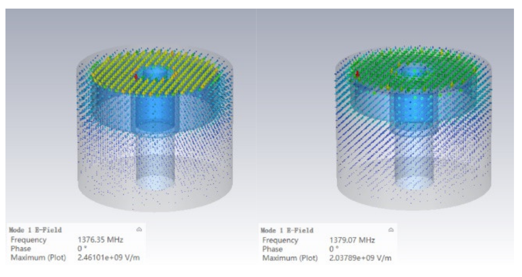
Figure 1. Schematic diagram of a parallel plate capacitor.
Electronics 11 01441 g001
Figure 2. Schematic diagram of (a) metal coaxial resonator and (b) dielectric-loaded resonator.
Electronics 11 01441 g002
Figure 3. Cascaded quadruplet topology.
Electronics 11 01441 g003
Figure 4. Coupling matrix of 1475 MHz bandpass filter.
Electronics 11 01441 g004
Figure 5. Frequency response of 1475 MHz circuit model.
Electronics 11 01441 g005
Figure 6. Schematic diagram of (a) metal resonant disk and (b) dielectric disk.
Electronics 11 01441 g006
Figure 7. Simulation circuit model of bandpass filter.
Electronics 11 01441 g007
Figure 8. CST single cavity simulation models for metallic coaxial resonators and dielectric-loaded resonators.
Electronics 11 01441 g008
Figure 9. Photograph of the fabricated 1475 MHz dielectric-loaded miniaturized cavity bandpass filter.
Electronics 11 01441 g009
Figure 10. Measured and simulated responses of the fabricated 1475 MHz dielectric-loaded cavity bandpass filter.
Electronics 11 01441 g010
Table 1. Relationship between permittivity and resonant frequency.
Relative Permittivity ε r 1.02.110
Resonant Frequency f (MHz)1726.91472.31008.4
Table 2. Comparison of the proposed filter performances with related published works.
Ref. f 0
(GHz)
Filter OrderSize
( λ g × λ g )
IL 1
(dB)
RL 2
(dB)
FBW 3GD 4
(ns)
[33]1.684none0.21 × 0.631.3224.00%none
[34]1.000none0.59 × 0.3231030.00%none
[35]2.60030.16 × 0.091.8253.00%none
[38]4.50020.28 × 0.093.010.060.00%≤0.4
[36]3.35020.12 × 0.092.420.05.97%≤2.5
[39]2.45020.15 × 0.132.420.01.63%none
This work1.47540.19 × 0.080.4920.06.10%≤21.3
1 insertion loss, 2 return loss, 3 functional bandwidth, 4 group delay.
Publisher’s Note: MDPI stays neutral with regard to jurisdictional claims in published maps and institutional affiliations.

