Abstract
The arrester plays an important role in the protection of the DC transmission system, and its thermal characteristics under different operating conditions greatly affect its performance. To study the thermal characteristics of multicolumn parallel arresters under extreme operating conditions in a DC system, considering the influence of SF6 fluid, the structural parameters of the ±500 kV Niu Cong DC transmission project were applied for this research. Firstly, a 3D model of the four-column parallel zinc oxide arrester installed on the neutral bus of the ±500 kV Niu Cong DC transmission project was built in ANSYS to analyze its thermal conduction. Then, the electromagnetic transient model of the Niu Cong DC transmission system was established in PSCAD to study the withstood energy of a four-column parallel zinc oxide arrester under 22 typical fault conditions in three operation modes. Based on the extreme operating conditions obtained, simulations of steady-state and transient thermal characteristics were performed considering the influence of SF6 fluid flow on the heat dissipation of the arrester. Finally, the field-test temperature test on the four-column parallel zinc oxide arrester was carried out to validate the effectiveness of the proposed simulation model and calculation method, with simulation data matching well with the field-test data. The results also conclude the thermal characteristics findings to reveal the thermal conduction of multicolumn arresters under extreme operating conditions.
1. Introduction
Zinc oxide arresters are an important component of power systems to prevent many kinds of overvoltage hazards [1,2,3]. According to the structure, there are two main types of arresters, i.e., single-column arresters and multicolumn parallel arresters [4,5]. At present, multicolumn parallel arresters are mostly used in high-voltage direct current transmission (HVDC) systems [6,7]. The fault transient characteristics of neutral bus multi-column parallel arresters were studied in [8], based on the Ningdong-Qingdao ±660 kV UHVDC transmission project. The analysis of the failure of a neutral point arrester in the manual grounding test of the ±800 kV Nuozhadu UHVDC transmission project is shown in [9]. In [10], the authors analyzed the fault of a neutral bus arrester in the Zhaotong ±500 kV converter station. These studies show that the current distribution between multiple-column shunt arresters is related to its current distribution coefficient.
“Thermal collapse” refers to the damage caused by the operating temperature of the arrester valve plate exceeding the limit value, which is closely related to the thermal characteristics of the arrester [11,12,13]. Many studies have shown that “thermal collapse” is often caused by excessive energy on the arrester [14]. However, in actual operation, the energy the collapsed multicolumn parallel arrester is subjected to is far less than its design value [15,16]. In a thermal collapse fault of the Nuozhadu-Guangdong UHVDC transmission project, the faulty arrester was only subjected to 11.9% of its design energy value [17]. The uniformity of current distribution between columns, which has an important effect on the total energy absorption capacity of the whole arrester, was studied in [18]. In order to take full advantage of its function in protecting the security of power system operation, it is necessary to analyze the thermal characteristics of multicolumn parallel arresters [19,20].
At present, there are few studies on the thermal characteristics of multicolumn parallel arresters, and most of them focus on scale models [21,22,23]. Ref. [22] investigated the current distribution characteristics of multi-column arresters under long-duration overvoltage impacts. The author of [23] analyzed the multi-physics field of the insulation deterioration of ZnO surge arresters. The temperature distribution characteristics of the 500 kV zinc oxide arrester were analyzed under different working conditions in [24]. The insulation reduction caused by the dampness of the arrester was analyzed in [25]. Fault analysis of a neutral bus arrester damaged in an artificial grounding test of the ±800 kV nuozhadu UHVDC transmission project was carried out in [26]. The main shortcomings of current research are summarized as follows. Firstly, for the simulation model, most current research focuses on steady-state analysis, and there is little research on the transient thermal characteristics of the most widely used four-column parallel arrester [27]. Secondly, from the perspective of simulation conditions, the existing research mostly focuses on the environment and the deterioration of the arrester itself without consideration of the arrester’s extreme electrical operating condition [9]. Thirdly, the existing models do not fully consider the effect of SF6 fluid on the heat dissipation characteristics [28,29].
This work was conducted based on the actual electrical parameters of the ±500 kV Niu Cong HVDC transmission project and the actual size parameters of the four-column parallel arrester. Firstly, the simulation model of a multicolumn parallel arrester was established by ANSYS. Then, PSCAD was used to simulate 22 typical extreme operating conditions corresponding to three operation modes of the Niu Cong DC transmission project, and the withstood energy of the arrester was calculated. Furthermore, based on the simulation results obtained, the steady-state and transient thermal characteristics of the neutral bus four-column parallel arrester were analyzed, considering the influence of SF6 fluid flow on the heat dissipation of the arrester. Finally, the field-test experiment was carried out, and the results are consistent with the simulation results, which validate the effectiveness of the proposed simulation model and calculation method. This research can provide a theoretical and practical reference for the optimal design of the thermal characteristics of multicolumn parallel structure arresters in DC power systems.
2. Computational Model
2.1. Arrester Calculation Model
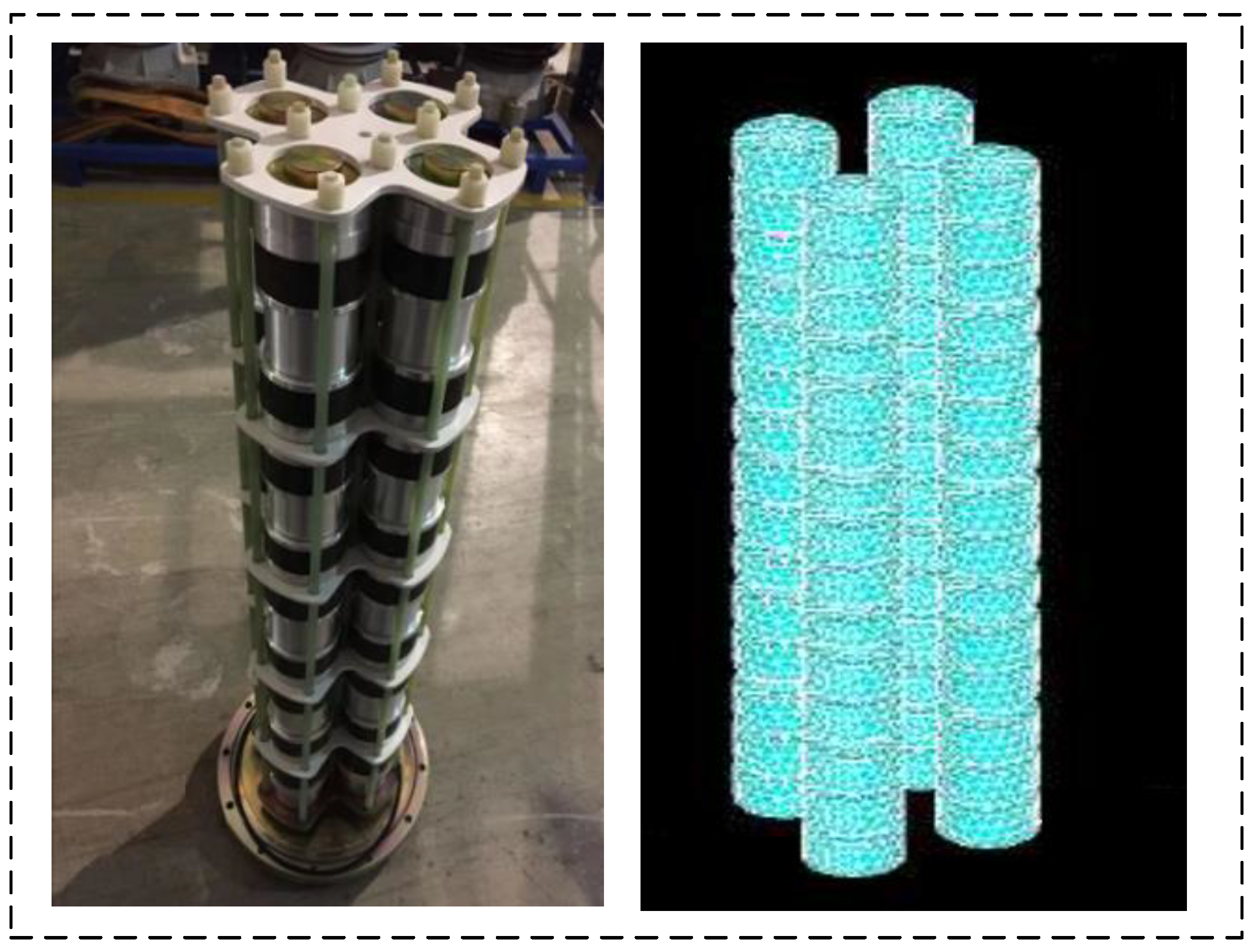
An equal-scale simulation model was established based on the neutral bus arrester (i.e., YH20W5-47/115) of the ±500 kV Niu Cong DC transmission project. The arrester used in this research was composed of four-valve plate columns, and each column had 18 cake-shaped valve plates. The valve plates were connected by aluminum gaskets, and the interior space of the arrester was filled with SF6 gas. The arrester structure and its simulation model are shown in Figure 1.
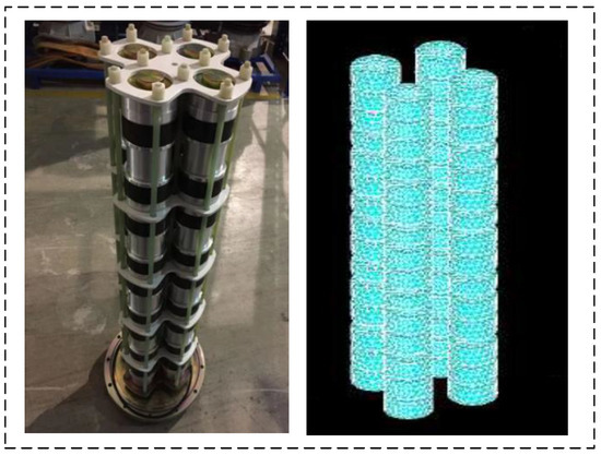
Figure 1.
The arrester structure and simulation model of the four-column parallel zinc oxide arrester.
ANSYS was used to establish the material properties of the four-column parallel zinc oxide arrester model and the model meshing is performed by the Tetra/Mixed mesh method. The material properties were set as shown in Table 1, which were obtained from factory data of the arrester. The thermal conductivity coefficient of SF6 is affected by temperature, and the thermal conductivity coefficient variation of SF6 with respect to the temperature is shown in Table 2; this information was obtained from the literature [30].

Table 1.
The material property settings of the four-column parallel zinc oxide arrester material.
Table 2.
The thermal conductivity coefficient variation of SF6 with respect to the temperature.
It should be noted that, in Table 2, T represents the temperature, and its unit is Kelvin. In order to simulate the working condition of the arrester, a cubic space of 10 m × 10 m × 10 m was set outside the arrester as its external environment.
2.2. Thermal Characteristic Calculation Model
2.2.1. Solid Thermal Conductivity Calculation Model
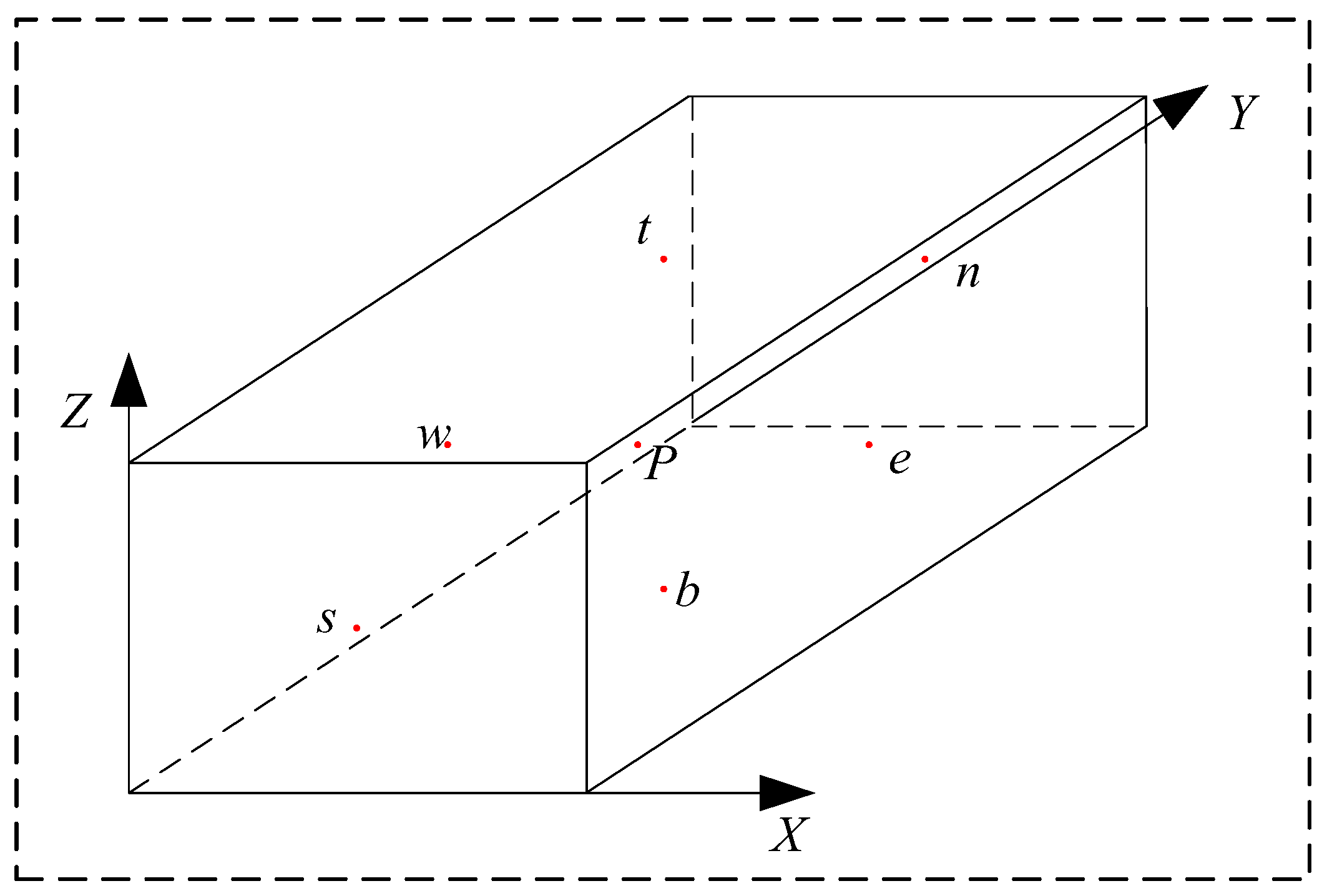
According to the finite volume method, a cuboid-shaped finite small-volume element was defined, as shown in Figure 2 below. Its length, width, and height are , , and , respectively. Thus, its volume can be expressed as . As shown in Figure 2, points {w, n, e, s, b, t} are the centers of each face of the cuboid, and point P is the center point of the whole cuboid.
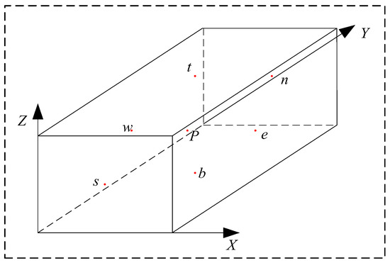
Figure 2.
The 3D schematic diagram of the rectangular type finite small volume cell.
According to the law of energy conservation and Fourier’s law of heat conduction, the general form of the differential equation for a three-dimensional active steady-state heat thermal conductivity model with an internal heat source [31] can be defined as follows:
where TP is the temperature at the center point P and k is the thermal conductivity coefficient, which is a constant. is the intensity of the internal heat source, i.e., the heat generation rate of unit volume. Equation (1) can be discretized to obtain (2).
where ke, ks, kt, kb, kw, and kn represent the thermal conductivities of the surfaces corresponding to points {w, n, e, s, b, t}, respectively; Te, Ts, Tt, Tb, Tw, and Tn represent the temperatures at the center point of each surface, respectively.
The discretized differential equation of the three-dimensional unsteady heat conduction model can be expressed as (3). The intermediate parameters can be obtained by (4) and (5).
where ρ is the density of the material and c is the specific heat capacity of the material at constant pressure. , , , , , and represent the temperatures at the initial time of each surface. f is a weighting factor whose value is between 0 and 1. When f is equal to 0, the initial value is used, and when is equal to 1, the eventual value is used.
2.2.2. Fluid Thermal Conductivity Calculation Model
According to fluid mechanics and heat conduction theory, fluid heat conduction involves mass conservation, momentum conservation, and energy conservation equations [32]. As shown in (6), the three-dimensional fluid convection differential equation can be obtained by combining the three above equations. The intermediate parameters can be obtained by (7) and (8).
where φ is a custom variable, u, v, and w are the flow velocities in the three-dimensional direction. γ is the diffusion coefficient.
2.3. Basic Assumptions and Boundary Conditions
To simplify the solution process, this paper makes the following reasonable assumptions:
- Multicolumn parallel arresters are in a steady flow state, and the thermal conductivity of SF6 fluid is only related to temperature.
- The Reynolds number of the SF6 fluid in the arrester is much less than 600, and the low Reynolds number K-ε model is used.
- The effects of fluid compression, buoyancy, and gravity are ignored.
- Each arrester can equally share the overvoltage energy generated by the entire system. Each column valve in the arrester equally divides the overvoltage energy flowing into the arrester.
- Considering that the contact surface between the arrester valve plate and the aluminum spacer is coated with an aluminum electrode with a lower resistivity, the contact resistance—which is much lower than the resistance of the valve plate itself—can be ignored.
The boundary conditions of the solving domain of the arrester simulation model established in this paper were set as follows:
- The initial simulation conditions are determined according to the measured value. The temperature is set to 300 K, and the atmospheric pressure is set to the standard atmospheric pressure.
- The wall boundary is set as the heat dissipation surface with the following boundary conditions [33].
- 3.
- The source and destination of energy in the simulation model satisfy the Lagrangian equation in the closed system.
- 4.
- The structural parts in the arrester model are all given as heat source bodies.
3. Analysis of Extreme Operating Conditions
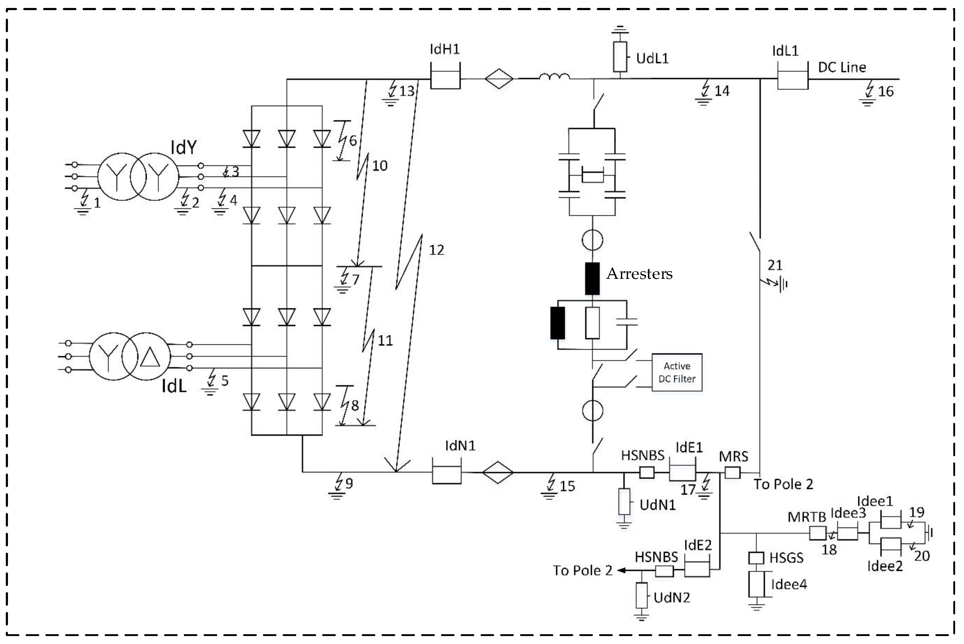
The simulation model is shown in Figure 3, which is based on the ±500 kV Niu Cong DC transmission system in China. The model is a double-loop bipolar single 12-pulse valve with a transmission capacity of 2 × 3200 MW, rated voltage of ±500 kV, and rated current of 3200 A. The multicolumn parallel zinc oxide arresters were connected to the neutral line, and their parameters are shown in Table 3. This study used PSCAD software to simulate and calculate the withstood voltage and current of the neutral bus arrester, under transient overvoltage under 22 typical fault conditions in three operation modes (i.e., symmetrical monopole operation, monopole earth loop operation, and monopole metal loop operation). Then, the withstood power and energy of the arrester were calculated in MATLAB as the input data of the thermal characteristic simulation.

Figure 3.
Schematic diagram of typical fault conditions in DC transmission systems.
Table 3.
Basic parameter of multicolumn parallel zinc oxide arresters.
The energy absorbed by the arrester is calculated according to (11).
where W is the energy absorbed by the arrester and t is the fault time of the arrester. U and I are the voltage and current withstood by the arrester.
The locations of 22 typical short current faults and their meanings are shown in Figure 3 and Table 4, respectively.
Table 4.
The marks and descriptions of 22 typical fault conditions.
3.1. Analysis of the Withstood Energy of Multicolumn Parallel Arrester under Symmetric Monopole Operation Mode
Under the symmetrical monopole operation mode, the simulation results of the withstood energy of multicolumn parallel arresters are shown in Table 5 below.
Table 5.
Arrester voltage, current, and energy of different fault conditions under symmetric monopole operation mode.
It can be seen from Table 4 that fault f2 is the worst operating condition for an arrester in the symmetric monopole operation mode, and the maximum energy withstood by a single arrester is 278 kJ.
3.2. Analysis of the Withstand Energy of Multicolumn Parallel Arrester under the Monopole Earth Loop Operation Mode
Under the monopole earth loop operation mode, the withstood energy of the arrester under different fault conditions is shown in Table 6. The results show that the withstood energy caused by the open circuit fault on the grounding pole (i.e., f18) is the largest.
Table 6.
Arrester voltage, current, and energy of different fault conditions under the monopole earth loop operation.
3.3. Analysis of the Withstanding Energy of the Arrester under the Monopole Metal Loop Operation Mode
As shown in Table 7, under the operation mode with a monopole metal return line, the worst operating condition is the short circuit fault on the DC pole line to the ground and the maximum withstood energy for the arrester is 540 kJ.
Table 7.
Arrester voltage, current, and energy of different fault conditions under the monopole metal loop operation mode.
4. Simulation Analysis of the Steady-State Thermal Characteristics of Arrester
There was a stable voltage on the multicolumn parallel arrester only when the Niu Cong DC system operated in the monopole earth loop operation and monopole metal loop operation modes, so this section analyzes the steady-state thermal characteristics under these two operation modes.
4.1. Steady-State Thermal Characteristic Analysis in the Monopole Metal Loop Operation Mode
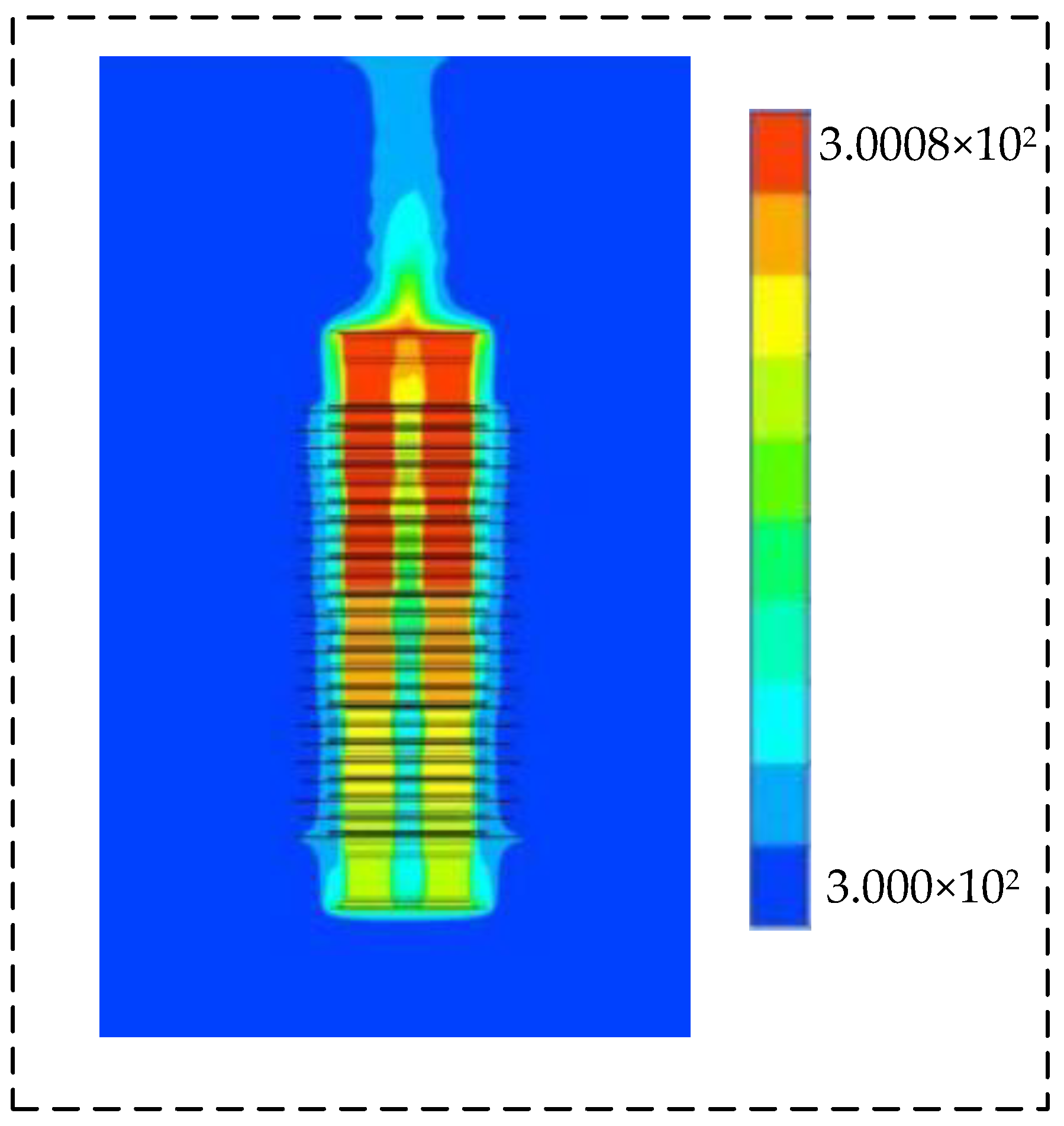
Figure 4 shows the overall spatial temperature distribution of the arrester under the operation of the monopole metal loop operation mode. The temperature range of the arrester is 300 K~300.8 K, and the temperature difference between different valve plates is very small. Therefore, under the monopole metal loop operation mode, the whole neutral bus arrester is in a heat balance state, and there is no obvious accumulated temperature phenomenon.

Figure 4.
Steady-state temperature distribution of the arrester under monopole metal loop operation mode.
In terms of the temperature distribution, both the solid valve plate area and the SF6 fluid area show the characteristics of high in the upper part and low in the lower part. At the same time, the temperature of the upper-half arrester does not have a significant impact on the surrounding environment, with only the air temperature above the arrester slightly increasing. This is because the heat dissipation effect inside the arrester is greatly affected by the space between the zinc oxide valve plates. The distance between the lower-half valve plates of the arrester model is larger than that of the upper-half valve plates, so the accumulated temperature phenomenon occurs in the upper half of the arrester.
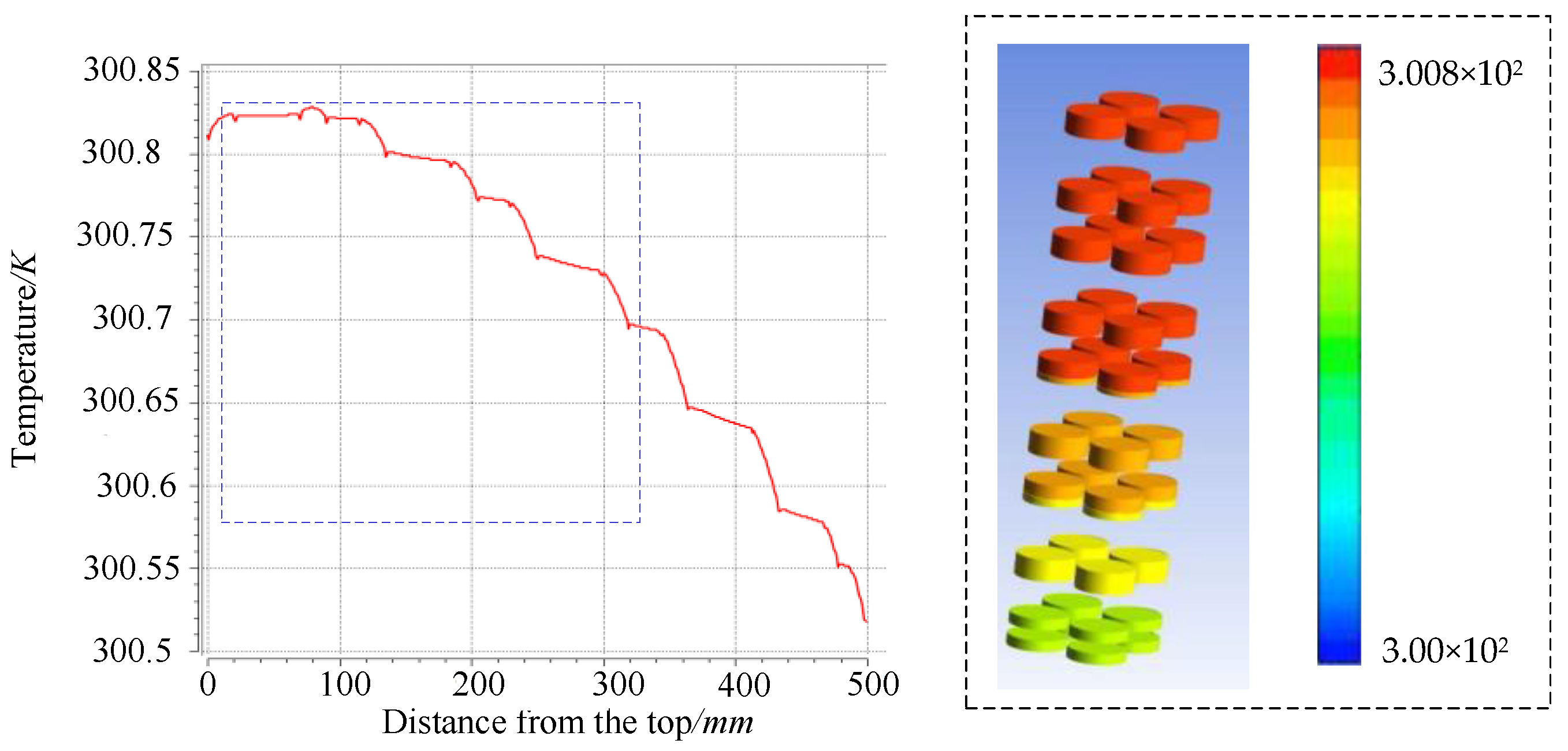
The temperature distribution of the column is shown in Figure 5. It can be found that the temperature distribution of the valve plates is uneven at the valve plates of group 5 and group 6. The temperature of the upper half column is significantly higher than that of the lower half column. The lower the position is, the faster the temperature of the valve plate decreases.
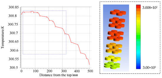
Figure 5.
Axial temperature distribution of valve plate column.
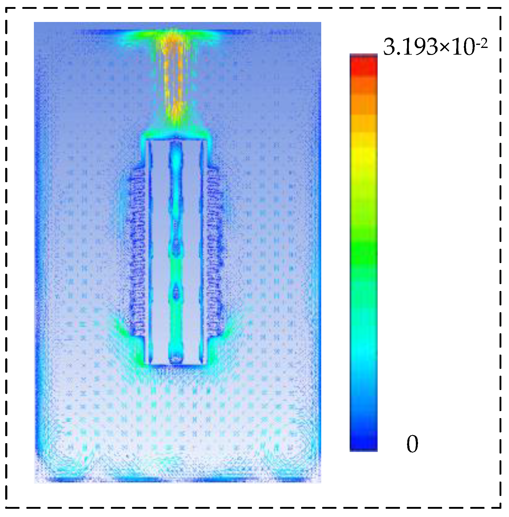
The flow line of SF6 fluid in the arrester is shown in Figure 6. The flow directions of SF6 fluid in different parts of the SF6 area are obviously different. Firstly, the fluid in the upper central area flows downward, while the fluid in the upper surrounding area flows upward. Secondly, the flow direction of the fluid in the lower half is upward. Thirdly, the flow velocity in the surrounding area is greater than that in the central area. This is mainly because the SF6 fluid between the valve plates column and the bushing heat would be heated up owing to its better dissipation performance, and the SF6 fluid between the valve blade columns decreases due to thermal buoyancy. The heated fluid gradually gathers in the upper part of the arrester, delaying the heat dissipation speed of the upper half column, this leads to the temperature difference between the upper and lower half columns.
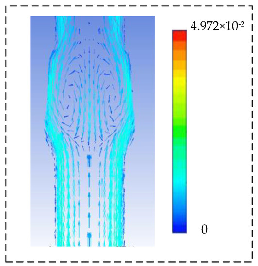
Figure 6.
The flow line diagram of the SF6 fluid in the multi-column arrester under monopole metal loop operation mode.
4.2. Steady-State Thermal Characteristic Analysis under Monopole Earth Loop Operation Mode
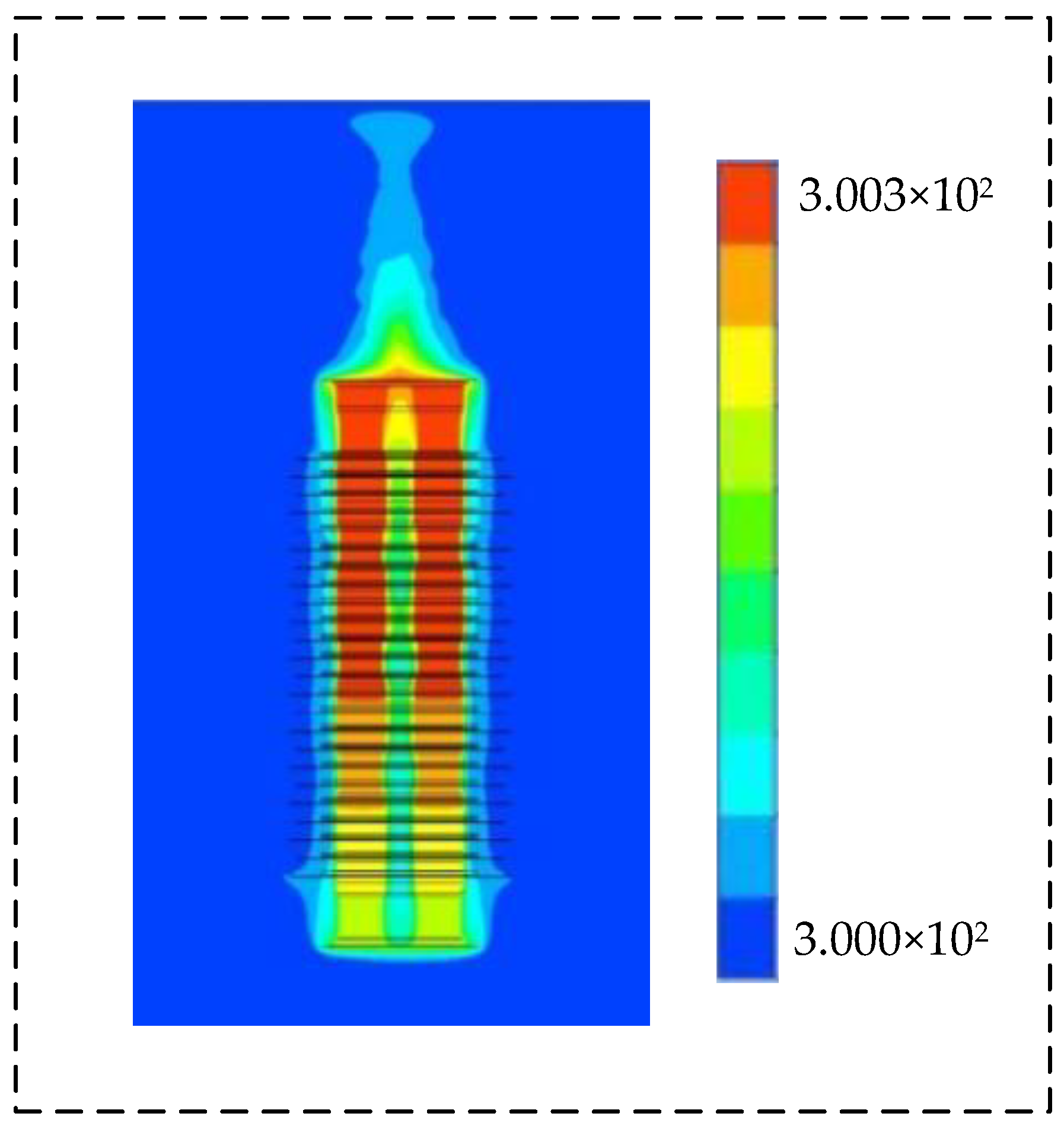
Under the monopole earth loop operation mode, the temperature range of the arrester is 300 K–300.279 K. The overall temperature distribution and fluid flow line diagrams are shown in Figure 7 and Figure 8, respectively. Compared with the operation mode of the monopole metal loop, the accumulated temperature of the arrester and the flow rate of the SF6 fluid are smaller in the operation mode of the monopole earth loop.

Figure 7.
Steady-state temperature distribution of the arrester under monopole earth loop operation mode.

Figure 8.
The flow line diagram of the SF6 fluid in the multi-column arrester under monopole earth loop operation mode.
Different from the monopole metal loop operation mode, the uneven temperature of the valve plates under the monopole earth loop operation mode are located in group 6 and group 8. The temperature of the valve plate slowly decreases along the axial direction, as shown in Figure 9. The decrease in withstood power reduces the heat generated by the arrester valve plates. The decrease in the fluid flow rate hinders the heat dissipation of the arrester, resulting in the slow heat dissipation of the arrester valve plate and the enlargement of the high-temperature area in the upper part of the arrester.
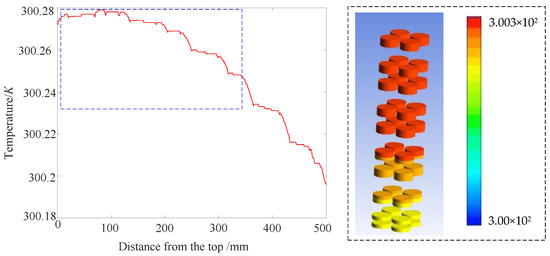
Figure 9.
Axial temperature distribution of the valve blade under monopole earth loop operation mode.
5. Simulation Analysis of the Transient Thermal Characteristic Analysis of Arrester
The temperature change caused by nonconstant or uncertain impulse current is called the transient thermal characteristics of the arrester. Because the operating conditions of fault f18 under monopole earth loop operation mode would lead to the largest withstood energy and the most severe working conditions for the multicolumn arrester, this section mainly focuses on the f18 fault as an example to analyze the thermal characteristic analysis of multicolumn arrester.
5.1. Transient Thermal Characteristic Analysis of the Whole Arrester
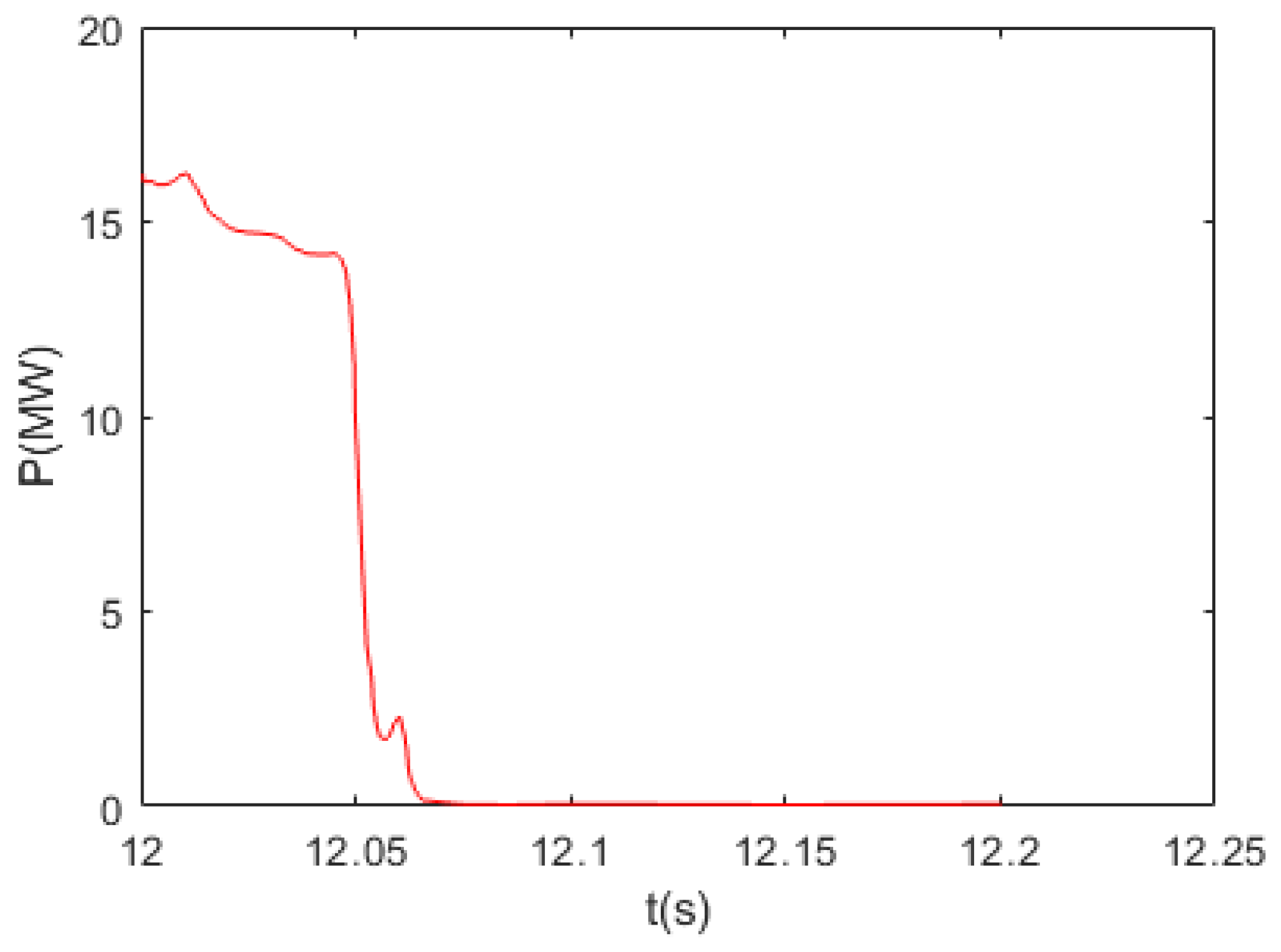
MATLAB was used to calculate the transient power at both sides of the arrester under the operating condition of fault f18, which was applied to the arrester model. As shown in Figure 10, the open circuit fault on the grounding pole (f18) occurs at 12 s, and the whole process lasts for 0.08 s.
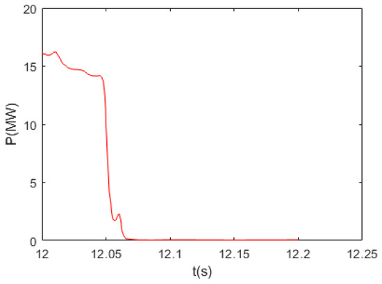
Figure 10.
Single arrester power curve under the fault f18.
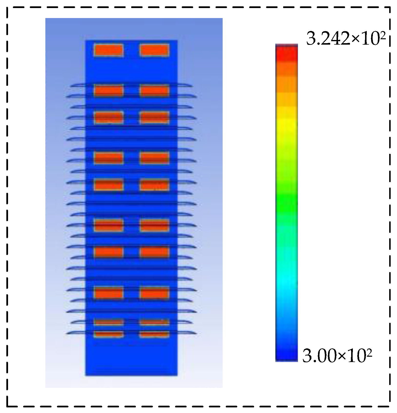
The temperature distribution and fluid flow line distribution of the whole arrester at the end moment of the fault (i.e., 12.08 s) are shown in Figure 11 and Figure 12. When the arrester experiences a transient impact, the temperature increase inside the arrester is mainly concentrated in the valve plates, with the temperature of the remaining regions kept almost unchanged. The highest temperature of the arrester valve plates is approximately 324.2 K. Fluid SF6 and silicone rubber bushing have no time to undertake the energy overload, which can only be stored in the valve plates for a short time. Therefore, the thermal collapse caused by the transient impact is highly likely.

Figure 11.
The transient temperature distribution of the arrester under the operating condition of fault f18.

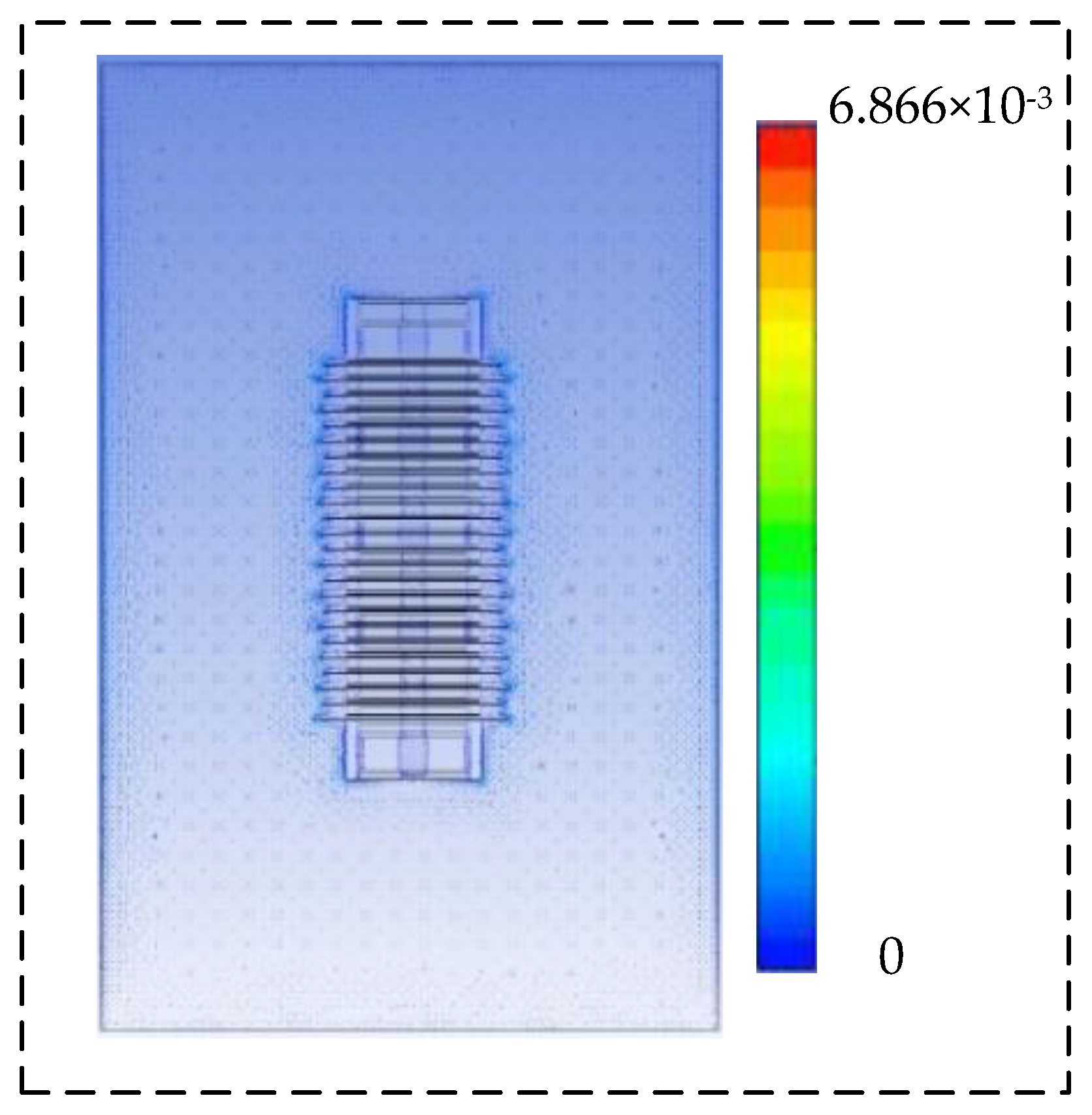
Figure 12.
The fluid flow velocity diagram.
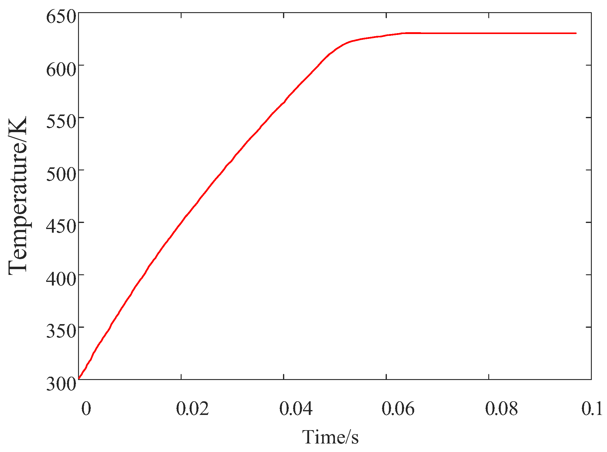
The current sharing characteristic is one of the crucial functions of the multicolumn parallel arrester. Assuming that the fault occurs with all the energy concentrated on a valve plate column, further analysis of the current sharing characteristic in the extreme situation was conducted. As shown in Figure 13, the transient temperature of the valve plate can reach 630.69 K, and the energy overload caused by fault f18 exceeded the short-term withstand energy valve of the arrester, which would most likely cause the thermal collapse of the valve plate.

Figure 13.
The temperature curve of the valve plate under the operating condition of fault f18.
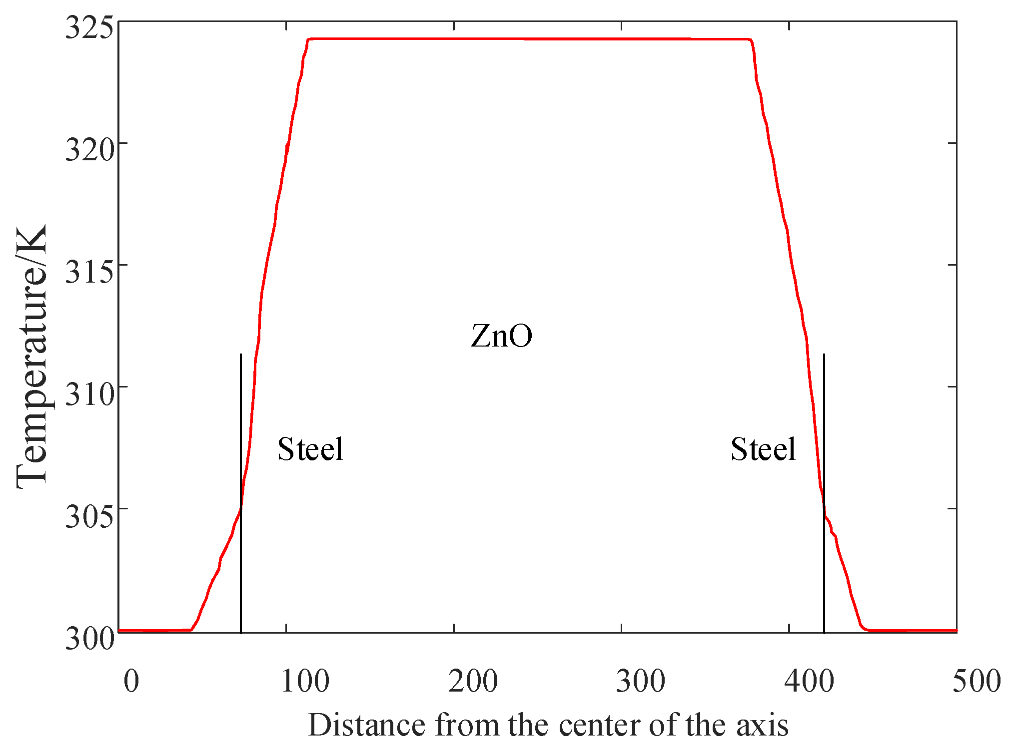
The transient thermal characteristics of single valve plates were further studied, and the temperature distribution of the seventh group of the valve plate is given in Figure 14. Although most of the heat concentrates in the valve plates, the temperature distribution is still uneven inside the valve plate, with its outer surface (contact with SF6) having a significantly higher temperature than the two bottom surfaces (contact with the steel material).
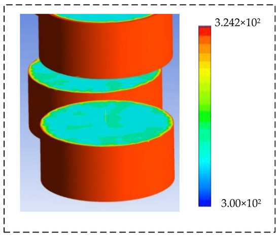
Figure 14.
The temperature distribution of the seventh group valve plate.
5.2. Transient Thermal Characteristic Analysis of Valve Plates
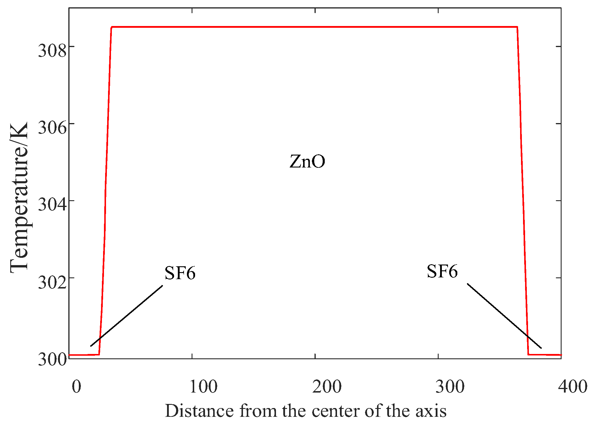
The axial and radial temperature variation curves of the group 7 valve plate are shown in Figure 15 and Figure 16. The temperature of the valve plate increases with the distance to the center of the valve plate decreasing, both along the radial and axial directions. The temperature gradient at the SF6 zinc oxide intersection is much steeper than that at the steel-zinc oxide intersection. This is mainly because the temperature distribution of the arrester valve plate is related to the thermal conductivity of its contact medium. The thermal conductivity of the steel material is much higher than that of SF6, so the heat of the zinc oxide valve plate can be quickly dissipated through the steel material. As for the SF6 fluid, due to its weak thermal conductivity, the heat gathers at the SF6 zinc oxide interface, which would lead to the temperature difference at the contact surface with a different medium.

Figure 15.
The axial temperature distribution of seventh group valve plate.
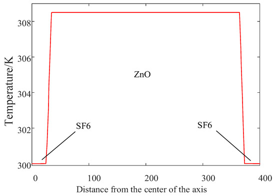
Figure 16.
The radial temperature distribution of seventh group valve plate.
5.3. Heat Dissipation Process Analysis
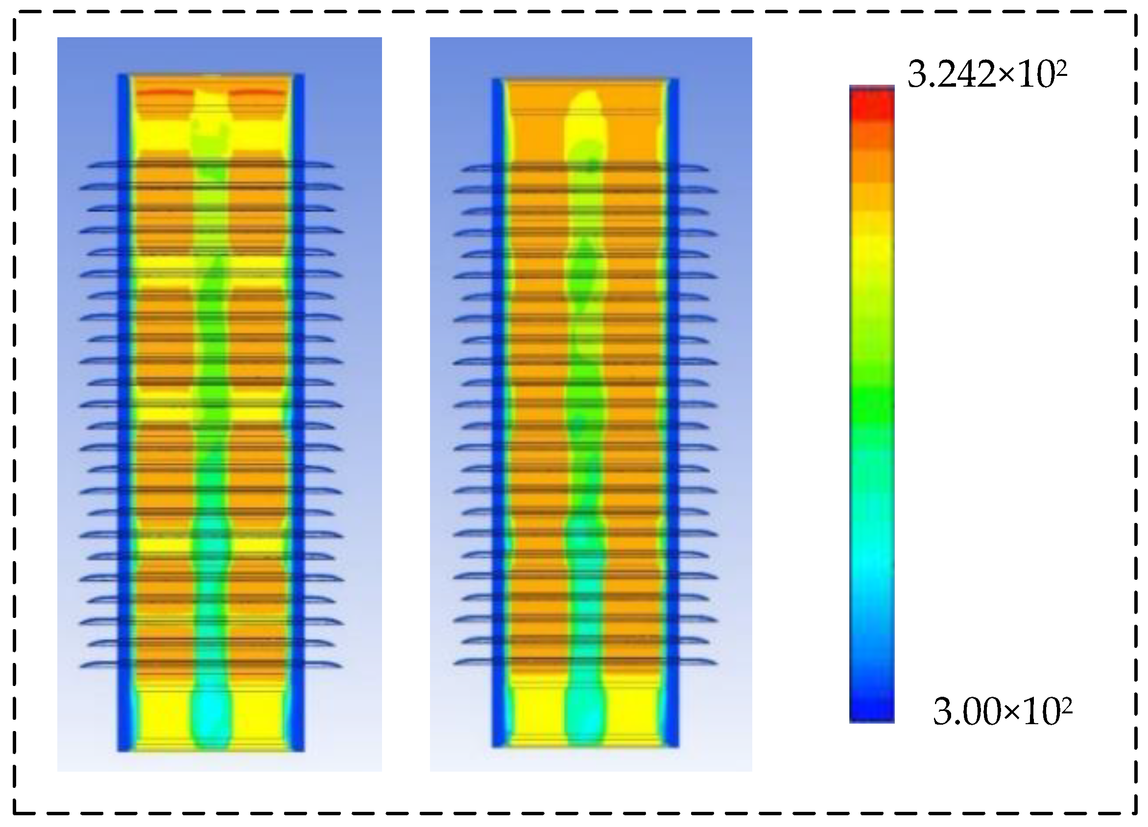
Further study on the heat dissipation process of the arrester after the transient impact was conducted. The temperature distributions of the arrester at the 35th second and 86th second after the transient impact are shown in Figure 17. Due to the low thermal conductivity of SF6, the valve plate surface in contact with SF6 fluid is almost in an adiabatic state, while the heat dissipation efficiency of the surface in contact with the steel side is high. The whole valve presents the characteristics of vertical heat dissipation. In addition, except for the upper and lower bottom surfaces of the silicone rubber bushing, the temperature of the surface minimally changes.
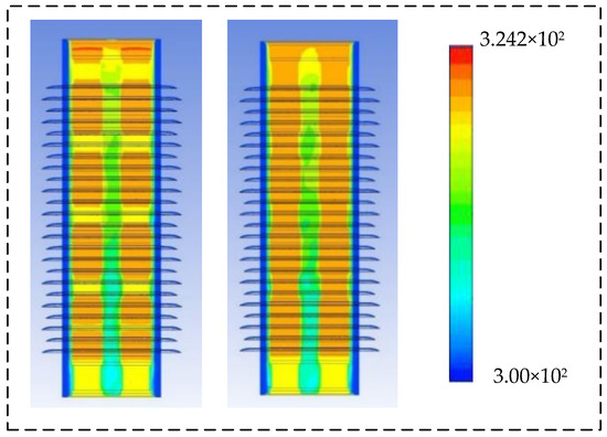
Figure 17.
The temperature distribution of the arrester at the 35th second and 86th second after the transient impact.
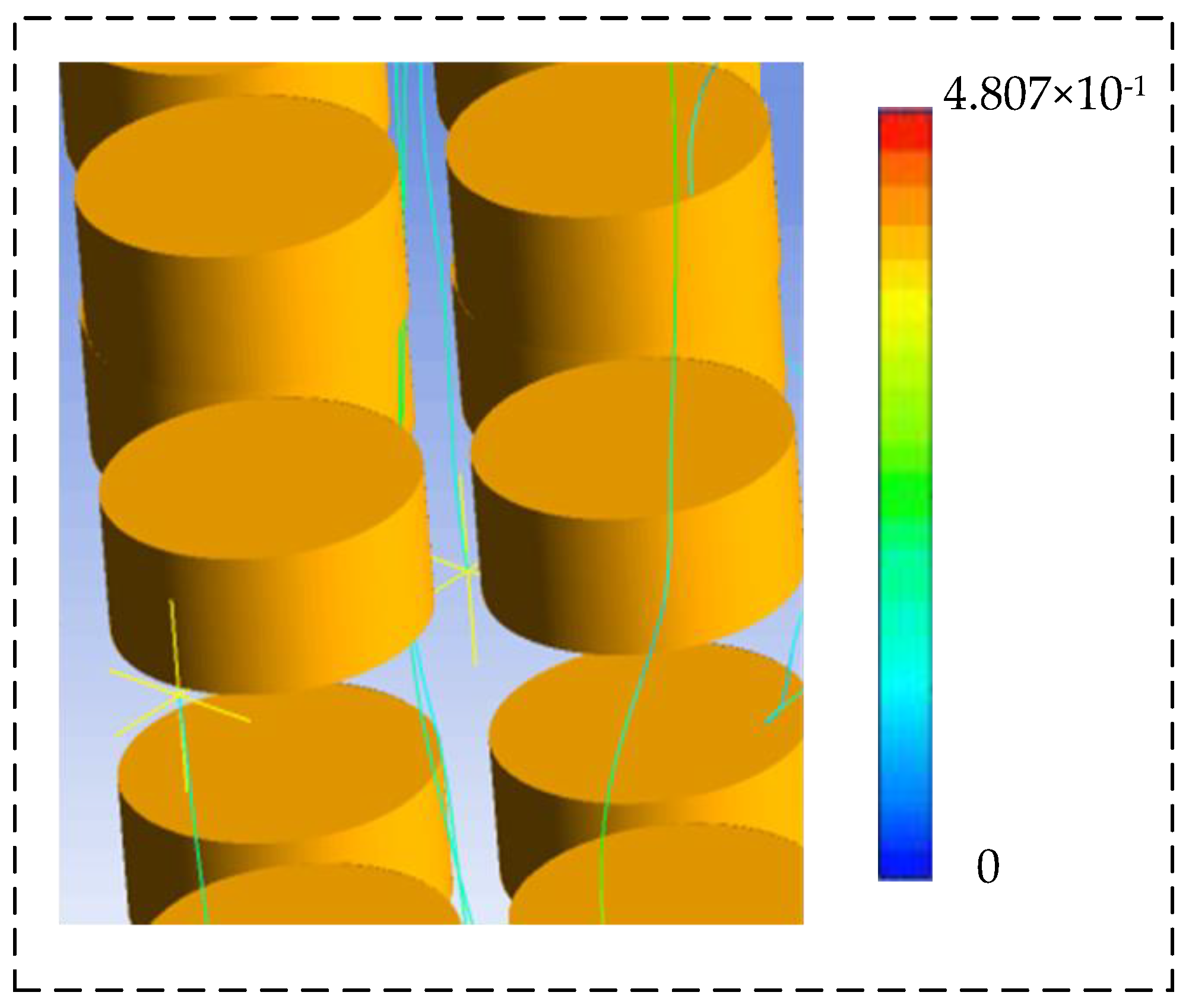
The flow line diagram of the SF6 fluid at the 35th second after transient impact is given in Figure 18. It can be seen that the flow direction of SF6 fluid is upward in the middle of the four-column valve plate, while the flow direction of SF6 fluid outside the four-column valve plate is forced to flow downward. The hot SF6 fluid is more likely to be pushed upward. The backflow of hot SF6 fluid in the closed space leads to the reduction of heat transfer efficiency between the gas and the inner wall surface of the bushing, resulting in the reduction of the heat dissipation rate of the upper half of the arrester.

Figure 18.
The flow line diagram of the SF6 fluid at the 35th second after transient impact.
6. Experimental Testing and Data Comparison
To verify the correctness of the thermal characteristic model and the accuracy of the calculation results, extreme working condition tests were carried out based on the Niu Zhai station of the ±500 kV Niu Cong DC project, and the same type and batch of arrester valve plate specimens was used for the temperature tests.
6.1. Extreme Operating Condition Model Verification
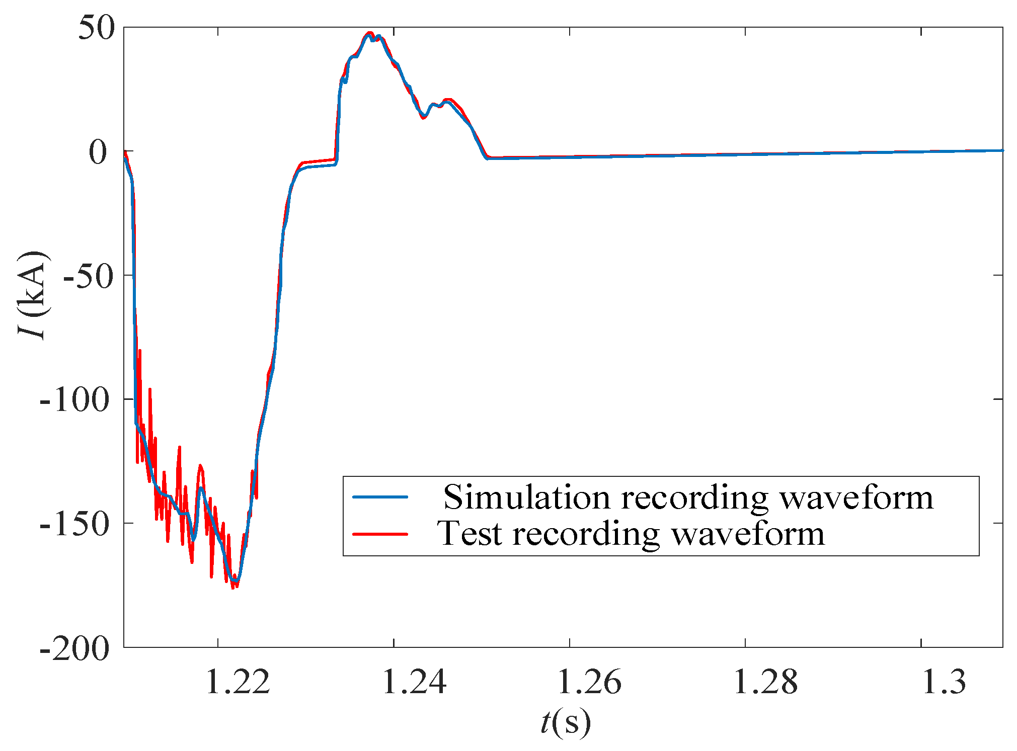
Because the ±500 kV Niu Cong DC high voltage transmission project has been put into production, many extreme short-circuit faults are difficult to be simulated on a real power system. The most extreme working condition test that can be simulated at the ±500 kV Niu Zhai station is the short circuit fault on the metal return line to ground under full-power operation mode of a monopole metal loop, i.e., fault f21. Fault f21t was simulated in engineering practice and its current waveform was measured. Then, the measured current waveform was compared with the current waveform obtained from the simulation to verify the feasibility of the extreme operating conditions obtained by the simulation. As shown in Figure 19, the current waveform of the field test almost coincides with the simulated recording waveform, which proves the feasibility of the extreme operating conditions obtained by simulation.

Figure 19.
The current waveforms of field-test and simulation.
6.2. Temperature Test Verification
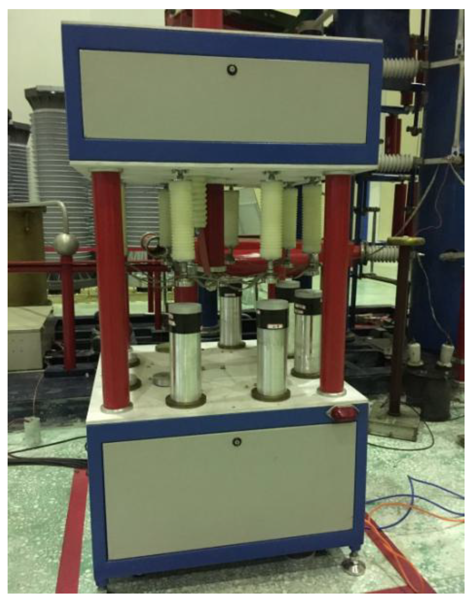
The off-line arrester with the same type as the actual arrester in the ±500 kV Niu Cong DC project was used for the field test. The field test was carried out by applying the operating impulse current to the off-line arrester with its energy equal to the withstood energy under different extreme operating conditions in the simulation experiment. Under different extreme operating conditions, the energy applied to the arrester was also different. Here, A 30/60 us operating impulse current with its current equal to 0.0475 kA was applied to the arrester, so that the energy absorbed by the arrester valve plate was consistent with the simulation results (i.e., 3.56 kJ). The test instrument on site is shown in Figure 20. The temperature of the valve plate was measured by infrared temperature measurement, and the measured values are compared with the simulation value in Table 8. The temperature calculation results and the field test results match well and the error is within the allowable range of practical application. Considering the impact of SF6 fluid on the heat dissipation in the arrester, the higher the temperature of the arrester valve plate is, the higher the gas flow velocity, which is a benefit for the heat dissipation of valve plates. In addition, because the inner space of the arrester is closed, SF6 fluid will gather at the top of the arrester, delaying the heat dissipation efficiency of the upper half part of the arrester.

Figure 20.
The temperature test device.
Table 8.
Comparison between simulated and measured temperature values.
It should be noted that, in the simulation experiment, the established model was idealized, and only limited environmental factors were considered. However, in the actual experiment, the outdoor environment was varied, including temperature, humidity, and pressure, which will have a certain impact on the results. Due to the difficulty in controlling the external environment in the actual field-test experiment, the more extensive experiment is limited.
7. Conclusions
This paper studies the steady-state and transient thermal characteristics of the neutral bus multicolumn parallel arrester under extreme operating conditions, with consideration given to the influence of SF6 fluid flow on heat dissipation. By comparing the simulation results with the field-test data of the Niu Zhai station of the ±500 kV Niu Cong project, it was found that the simulation results match well with the measured data, which validates the effectiveness of the proposed model and calculation method. The main conclusions of this paper are summarized as follows:
- The energy overload of arresters under twenty-two typical faults in three operation modes in the Niu Cong DC transmission project was simulated, and the simulation results show that the energy overload caused by open-circuit faults on the grounding pole under the monopole earth loop operation mode is the highest, and although the energy overload generated is still within the tolerable range of the arrester, it exceeds the tolerable range of the single valve plate.
- The results of the simulation show that the steady-state thermal temperature distribution of the whole arrester changes little, and most of the heat is concentrated in the upper half of the arrester. The heat of the valve plate can be diffused via SF6 fluid, but the hot fluid gathered at the top of the arrester would lead to the temperature above the metal plate of the arrester being relatively high.
- The heat dissipation process shows that the heat dissipation efficiency of the region near the steel gasket is higher than that of other regions in the arrester. Thus, the metal gasket between the valve plates can accelerate the heat dissipation efficiency and help the arrester to return to a steady-state thermal equilibrium state to avoid the spread of thermal collapse inside the arrester.
In the future, the established model will be applied to other DC transmission systems with different voltage levels in China to study the thermal characteristics of multicolumn parallel zinc oxide arresters under extreme operating conditions. The aging characteristics of multicolumn parallel zinc oxide arresters will be studied to research the influence of the aging phenomenon on their steady-state and transient thermal characteristics under extreme operating conditions.
Author Contributions
Conceptualization, Y.F.; methodology, Y.F. and P.Z.; software, P.Z. and B.S.; validation, P.Z. and D.W.; formal analysis, P.Z.; investigation, W.L.; resources, D.Z.; data curation, Z.C.; writing—original draft preparation, P.Z. and B.S.; writing—review and editing, Z.Z., W.W.; visualization, Z.Z.; supervision, Y.F. All authors have read and agreed to the published version of the manuscript.
Funding
This research received no external funding.
Data Availability Statement
Data sharing not applicable.
Conflicts of Interest
The authors declare no conflict of interest.
References
- Xie, S.; Su, S.; He, H.; Guo, R.; Liu, F.; Zhang, C. Internal overvoltage and insulation coordination of electrode line in HVDC project. High Volt. Eng. 2018, 44, 2331–2337. [Google Scholar]
- Zhang, Y.; Yang, Q.; Xie, S.; Zhang, C. Mechanism and Application of Arrester Block Voltage Division to Lightning Transient Voltage Monitoring in Substation Transformers. IEEE Trans. Electromagn. Compat. 2019, 61, 689–696. [Google Scholar] [CrossRef]
- Liu, S.; Huang, F.; Yu, S.; Zeng, H.; Lei, X.; Liao, W. Study on overvoltage of UHV DC grounding line. High Volt. Eng. 2018, 44, 2410–2417. [Google Scholar]
- Zhao, Z.; Qian, M.; Yang, H.; Shen, J.; Zheng, Q.; Wang, T.; Shi, B.; Xie, M. AC Intrusion Overvoltage Protection in Secondary DC System Based on Zinc Oxide Arrester. Insul. Surge Arresters 2021, 4, 87–91. [Google Scholar]
- Wang, L.; Bii, X.; ZHU, Z.; SUN, Y. Research on Eddy Current Loss and Fluid-solid Coupling Heat Transfer in the End Region of Synchronous Condenser for UHV Transmission. Proc. CSEE 2022, 42, 1968–1981. [Google Scholar]
- Lu, W.; Liu, W.; Li, W.; Chen, W.; Zhu, J. Research on current distribution test of neutral-bus arresters multicolumn parallel connected in converter station. In Proceedings of the 2016 IEEE PES Asia-Pacific Power and Energy Engineering Conference (APPEEC), Xi’an, China, 25–28 October 2016; pp. 1719–1724. [Google Scholar]
- Jiang, Z.; Gan, P.; Zhang, Z.; Yuan, J.; Zhang, Z. Study on current sharing characteristics of arrester for UHV DC. In Proceedings of the 2019 IEEE PES Asia-Pacific Power and Energy Engineering Conference (APPEEC), Macao, China, 1–4 December 2019; pp. 1–5. [Google Scholar]
- Liu, Z.; Yu, X.; Li, X.; Li, J.; Guo, J.; He, J.; Yu, J. Fault Simulation of Neutral Bus Arrester in DC Converter Station. Insul. Surge Arresters 2022, 2, 86–92. [Google Scholar]
- Jia, L.; Cai, H.; Chen, X.; Liu, G.; Hu, S.; Shi, J. Fault Analysis and Simulation on Neutral Bus Arrester in Nuozhadu-Guangdong UHVDC Project. Electr. Power Constr. 2015, 36, 123–128. [Google Scholar]
- Wang, D.; Liu, J.; Jiang, L.; Pi, T.; Li, D. Analysis and Countermeasure of Neutral-Bus Arrester Fault in ±500 kV Zhaotong Converter Station. Insul. Surge Arresters 2017, 4, 132–135. [Google Scholar]
- Zhou, P.; He, H.; Li, Z.; Wang, L.; Lou, Y. Parameters Selection for the Neutral Arrester Beside Neutral Grounding Reactor at the Neutral Point of Shunt Reactors on 1000kV Double-circuit Line. High Volt. Eng. 2021, 47, 1606–1616. [Google Scholar]
- Li, P.; Qu, Y.; Fang, B.; Wang, Y.; Wu, T.; Pu, Z. Calculation of Temperature Distribution Characteristics of 500 kV Metal Zinc Oxide Arrester under Different Fault Conditions. Sci. Technol. Eng. 2021, 21, 3649–3655. [Google Scholar]
- Liu, L.; Li, C.; Zhang, W.; Si, W.; Liu, J. Study of Nonlinear Conductivity Materials for Improving Nonuniform Electric Field of ZnO Arrester. J. Hubei Univ. Technol. 2021, 36, 26–30. [Google Scholar]
- Shariatinasab, R.; Gholinezhad, J.; Sheshyekani, K. Estimation of Energy Stress of Surge Arresters Considering the High-Frequency Behavior of Grounding Systems. IEEE Trans. Electromagn. Compat. 2018, 60, 917–925. [Google Scholar] [CrossRef]
- Zeng, G.; Wang, X.; Liu, S.; Liu, B.; Zhang, S.; Liu, B.; Kui, Z.; Wang, Z.; Li, S. Simulation Analysis of Temperature Rise Distribution Characteristics of Damp Arrester. Hubei Electr. Power 2020, 44, 34–41. [Google Scholar]
- Wang, L.; Ren, X.; Huang, H.; Yao, Z. The Development Trends of Zinc Oxide Varistor Used in Surge Arrester Both in China and Abroad. Insul. Surge Arresters 2021, 06, 30–44. [Google Scholar]
- Wang, J.; Du, Z.; Zou, J.; MA, Z.; Xie, Y. Experimental study of the influence of air temperature on the state parameters of ZnO arrester. Eng. J. Wuhan Univ. 2020, 53, 430–434. [Google Scholar]
- Lu, W.; Zhang, P.; Wen, W.; Chen, Z.; Liu, W.; Wang, G. Influence of impulse current waveform on current distribution of multi-column arresters. Eng. J. Wuhan Univ. 2019, 52, 630–634. [Google Scholar]
- Xiao, X.; Lu, W.; Wei, X.; Chu, J.; Liu, W.; Wen, W. The Effects of Temperature on Current Distribution Characteristic of Multi-column Surge Arrester. In Proceedings of the 2021 International Conference on Advanced Electrical Equipment and Reliable Operation (AEERO), Beijing, China, 15–17 October 2021; pp. 1–4. [Google Scholar]
- Späck-Leigsnering, Y.; Ruppert, M.G.; Gjonaj, E.; Gersem, H.D.; Hinrichsen, V. Simulation Analysis of Critical Parameters for Thermal Stability of Surge Arresters. IEEE Trans. Power Deliv. 2022, 37, 871–879. [Google Scholar] [CrossRef]
- Yang, Y.; Deng, W.; Luo, R.; Shi, Z.; Wei, S. Analysis of Temperature for 500 kV ZnO Surge Arrester Based on Thermal-Electric Coupling. Insul. Surge Arresters 2019, 3, 98–104. [Google Scholar]
- Lu, W.; WEN, W.; Liu, W.; Zhang, D.; Wang, Q. Current Distribution Characteristic of Multi-column Surge Arresters Under Long Duration Overvoltage. High Volt. Eng. 2019, 45, 3280–3289. [Google Scholar]
- Yang, Y. Analysis of Multi-Physics Field on the Insulation Deterioration of EHV or UHV ZnO Surge Arresters; Changsha University of Technology: Changsha, China, 2018. [Google Scholar]
- Deng, W.; Shi, C.; Luo, R.; Wei, S.; Yang, Y. Temperature Distribution Characteristics of 500 kV Zinc Oxide Arrester Resistance Sheet. High Volt. Appar. 2017, 53, 192–197. [Google Scholar]
- Zhang, P. Research of Potential Distribution of Ultra and Extra ZnO AC/DC Arrester under Different Conditions; Huazhong University of Science and Technology: Wuhan, China, 2017. [Google Scholar]
- Zhou, C.; Wang, C.; Hu, H.; Yuan, H. Research Analysis on Neutral-bus Arrester Fault of Tian-Guang HVDC System. Guangdong Electr. Power 2016, 29, 74–79. [Google Scholar]
- Lu, W.; Chen, W.; Li, W. Fault Analysis of Neutral Bus Arrester Damaged in Artificial Grounding Test of ±800 kV Nuozhadu UHVDC Transmission Project. Insul. Surge Arresters 2015, 5, 149–153. [Google Scholar]
- Sang, J.; Wu, L.; Liu, Y.; YU, L. Study on the Thermal Characteristic of Polymeric Housed MOA without gap. Insul. Surge Arresters 2015, 3, 62–68. [Google Scholar]
- Xie, B.; Diao, Q.; Wang, J.; Xian, R.; Gao, H. Analysis of Abnormal Heating of 220 kV Metal Oxide Arrester. Electr. Eng. 2022, 19, 151–154. [Google Scholar]
- Liu, F. Decomposition Characteristic of SF6under PD&Recognition of PD Category and Calibration of Impact Factors; Chongqing University: Chongqing, China, 2013. [Google Scholar]
- Sang, J. Study on Thermal Equivalency of Arrester and the Steady-State Thermal Behaviors of Polymeric Housing Arrester. Insul. Surge Arresters 2013, 2, 53–58. [Google Scholar]
- He, Z.; Chen, W.; Chen, X.; Zhang, B.; Yan, X. Calculation Method for Transient Thermal Characteristics of Multi-column Parallel Structure Surge Arrester. High Volt. Eng. 2012, 38, 2129–2136. [Google Scholar]
- Liu, S.; Popov, M.; Belda, N.A.; Smeets, R.P.P.; Liu, Z. Thermal FEM Analysis of Surge Arresters During HVDC Current Interruption Validated by Experiments. IEEE Trans. Power Deliv. 2022, 37, 1412–1422. [Google Scholar] [CrossRef]


Disclaimer/Publisher’s Note: The statements, opinions and data contained in all publications are solely those of the individual author(s) and contributor(s) and not of MDPI and/or the editor(s). MDPI and/or the editor(s) disclaim responsibility for any injury to people or property resulting from any ideas, methods, instructions or products referred to in the content. |
© 2022 by the authors. Licensee MDPI, Basel, Switzerland. This article is an open access article distributed under the terms and conditions of the Creative Commons Attribution (CC BY) license (https://creativecommons.org/licenses/by/4.0/).