Article

Research on the Electromagnetic Characteristics of an Integrated Multi-Winding Inductive Filtering Converter Transformer and Its Filter System

1
School of Computer and Electrical Engineering, Hunan University of Arts and Science, Changde 415000, China
2
Key Laboratory of Hunan Province for Control Technology of Distributed Electric Propulsion Air Vehicle, Changde 415000, China
*
Author to whom correspondence should be addressed.
Electronics 2023, 12(1), 227; https://doi.org/10.3390/electronics12010227
Submission received: 5 December 2022 / Revised: 27 December 2022 / Accepted: 27 December 2022 / Published: 2 January 2023
(This article belongs to the Special Issue IoT Applications for Renewable Energy Management and Control)

Abstract

:
In this paper, the electromagnetic characteristics of a novel integrated multi-winding inductive filtering converter transformer, including two parallel-connected delta filter windings with zero impedance, are studied. First, based on Ansoft, a 3D FEM model of the novel converter transformer is built according to its structural parameters and material characteristics. Next, the external circuit connection based on the established 3D FEM model is realized so the corresponding field-circuit coupling model can be established under three different working conditions. On this basis, the electric field characteristics, magnetic field characteristics, winding electromagnetic force characteristics, and core loss characteristics of the novel converter transformer with different conditions are analyzed. The results show that because the harmonic current is effectively suppressed, the flux chain passing through the windings of the novel converter transformer is closer to the sinusoidal wave and the harmonic magnetic potential is effectively suppressed; the electromagnetic force received by each winding of the converter transformer and the high-frequency vibration component are significantly reduced; and the transformer core loss is also significantly reduced. The research on the internal electromagnetic characteristics of the integrated multi-winding inductive filter converter transformer reveals the mechanism of reducing vibration and noise.

1. Introduction

Compared with traditional passive power filtering and active power filtering, inductive filtering technology is a new method. It can make full use of the electromagnetic potential of a transformer, realize the performance of an approximate active filter with the cost of a passive filter, and fundamentally change the influence of harmonic and reactive power on the converter transformer. It has broad application prospects [1,2,3,4]. The core idea of inductive filtering theory is based on the principle of a harmonic ampere turn balance of a transformer, combining the unique zero-equivalent impedance design of filter winding with the tuned filter device configured in the filter branch to suppress harmonics and compensate the reactive power on the valve side [5,6,7,8,9]. The advantages of this technology are mainly reflected in three aspects. On the one hand, it overcomes the partial tuning design problem of the filter in the traditional passive filtering method and realizes the full tuning design of the filter to obtain the best filtering effect. Next, the transfer path of the harmonic and reactive power in the system is changed, which reduces the harmonic and reactive power loss of the converter transformer, improves the power supply efficiency, and realizes energy savings and consumption reduction. Moreover, it also greatly reduces the harmonic magnetic flux in the transformer core and significantly reduces the vibration and noise caused by the harmonics in the converter transformer [10].
In [11], a green and energy-saving DC power supply system based on inductive filtering technology was presented to solve the problems of serious harmonic contamination and large losses in existing industry thyristor rectifier systems. The practical testing results showed its unique superiority in harmonic suppression and energy savings. In [12], a novel rectifier system based on a harmonic suppression rectifier transformer and its filter system was presented to solve the problems of harmonic suppression and reactive power compensation that exist in a traditional industrial rectifier system. The harmonic suppression and reactive power compensation of the new rectifier system were remarkable, and the harmonic content in the grid-side winding current of the rectifier transformer was greatly reduced. The transfer path of harmonic and reactive power in the system was changed, thus reducing the harmonic and reactive power loss. The mechanism of harmonic flux suppression was discussed in [13]. In the novel converter transformer, the filter winding designed with zero impedance and the corresponding filter device designed with full tuning constituted a superconductivity closed loop. It always induced a harmonic flux of an equal size and opposite direction to offset the harmonic flux generated in the valve-side winding. On this basis, the internal electromagnetic environment of the transformer core was improved and the electromagnetic potential of the transformer was brought into full play. In [14], the working principle of a new 12-pulse converter transformer and its filter system with an extended side delta connection for DC transmission systems was analyzed and revealed its advantages in harmonic treatment. In reference [15], a 12-pulse integrated multi-winding inductive filter converter transformer with parallel topology of two delta filter windings applied to an HVDC conversion station was proposed, as well as the corresponding filter system. Compared to the system in [14], it achieved the same filtering effect while omitting the fifth and seventh harmonic filters, and the complete isolation and shielding of the third harmonic at the valve side were also realized. In addition, through mathematical modeling and equation derivation, the harmonic suppression mechanism of an inductive filtering converter transformer and its filtering system was studied, and the influence of inductive filtering technology on the harmonic transfer path was analyzed. The above studies are of great significance, however, there they also have some deficiencies. For example, in [11,12,13,14], the internal electromagnetic characteristics of an inductive converter transformer were not discussed in depth, and in [15], the mechanism of inductive filtering technology to reduce the transformer’s vibration and noise was not revealed. Therefore, it is necessary to further study the electromagnetic characteristics of a novel converter transformer and its filtering system to maximize its utilization.
Taking the integrated multi-winding inductive filter converter transformer and its filter system prototype used in a back-to-back HVDC converter station in [15] as the research object, the internal electromagnetic characteristics of the converter transformer are studied using the field-circuit coupling method in this paper [16,17,18,19,20]. First, based on Ansoft, the single-phase 3D FEM model of the converter transformer is constructed according to its structural parameters and material characteristics. Then, the external circuit connection based on the 3D FEM model is realized and the field-circuit coupling model is established. On this basis, under a set of three working conditions, the electric field characteristics, magnetic field characteristics, winding electromagnetic force characteristics, and core loss characteristics of the inductive filter converter transformer are analyzed. The research on the internal electromagnetic characteristics of the novel converter transformer is of great significance to reveal the fundamental mechanism of inductive filtering technology and how inductive filtering technology can reduce the harmonic loss, vibration, and noise of the converter transformer to lay a foundation for the popularization and application of a novel converter transformer.
The remainder of this paper is organized as follows. Section 2 provides an introduction to the field-circuit coupling method. In Section 3, the field-circuit coupling modeling of the novel converter transformer is built. Section 4 focuses on electromagnetic characteristic analysis through field-circuit coupling finite element simulations. Finally, the conclusion of this paper is given in Section 5.

2. Field-Circuit Coupling Method

The field-circuit coupling method, which is widely used in the analysis of electromagnetic fields in transformers, is suitable for dealing with the synergy of the transient magnetic field and coupling circuit. The core idea is to divide the transformer into an interior and exterior. The interior is treated as differential and calculated by the finite element method. On the other hand, the exterior is the external circuit composed of circuit elements such as the power supply, inductance, capacitance, and resistance. Then, the unknown quantity in the system is introduced into the electromagnetic field equation to complete the coupling analysis of the two [21,22,23,24,25]. Field-circuit coupling can take the electrical and magnetic transition processes of the transformer into account, which is very effective and fast for analyzing the internal electromagnetic field of the transformer. In the analysis of 3D nonlinear time-domain low-frequency transient electromagnetic fields, the Maxwell equation can be written as
× H = σ E × E = B t · B = 0
On this basis, two identities, as shown in Equation (2), can be obtained:
× 1 σ × H + B t = 0 · B = 0
In the solution, the first-order element is used to calculate the vector potential degrees of freedom on its edges, whereas the second-order element is adopted to calculate the scalar potential on the nodes.
When using the finite element method to analyze the electromagnetic field of an inductive filter converter transformer, the three time spaces around the transformer can be approximately regarded as the electromagnetic field distribution area. In addition, when the displacement current is ignored, the following equation can be obtained from the Maxwell equation:
× H = J s σ A t
where J s is the current density in each winding; H is the magnetic field intensity; σ is the conductivity of the material; and σ A / t is the eddy current density.
When the hysteresis effect is ignored, the following equation can be obtained:
H = 1 μ B = 1 μ ( × A )
where B is the magnetic inductive intensity of the core; μ is the permeability of the core material; and A is the magnetic potential vector. According to Equations (3) and (4), the transient electromagnetic field equation is as follows:
x 1 μ x A x + y 1 μ y A y + z 1 μ z A z = J s + σ A t
The matrix form obtained by discretizing the weighted integral of Equation (5) can be expressed as
[ K ] { A } + [ Q ] t { A } [ C ] { I } = 0
where A is the magnetic potential vector. C represents the correlation matrix of the interaction between the coil current and each unit node. I represents the branch current where the winding is located. Q is the coefficient matrix, which is determined by the type of element used. K is also a coefficient matrix and is a function of B that is related to the permeability of each unit. When the permeability of the transformer core is in the linear range, K is a constant coefficient matrix.
The winding in the finite element area is connected with the external circuit. When considering the end effect caused by the end leakage reactance, the voltage control equation of the winding can be acquired as follows:
U = E + R i + L d i d t
where U is the applied voltage. i represents the transformer winding current. E is the induced electromotive force in the winding. R indicates the resistance in the external circuit. The inductance in the external circuit is L.
The induced electromotive force equation of the transformer winding in the finite element region can be obtained according to the change in the flux in the cross-link of the winding:
E = n c S c t Ω A · h d Ω
where Ω is the scalar magnetic potential, n c denotes the turn number of the transformer windings, S c represents the cross-sectional area of the transformer winding, and h is the winding tangential unit vector.
According to Equations (7) and (8), the equivalent circuit equation in the external circuit can be obtained by
U = n c S c t Ω A · h d Ω + R i + L d i d t
If the above equation is expressed in matrix form, there are
[ C ] T t { A } + [ L ] d d t { I } + [ R ] { I } = [ U ]
Combining Equations (6) and (10), a spatial numerical discrete field-circuit coupling model expressed by the coupling of the transient electromagnetic field and winding circuit equation for studying the electromagnetic transient process can be obtained, as shown in Equation (11):
K C 0 R A I + Q 0 C T L d d t A I = O U
The time-domain model represented by the above equation is discretized according to the Crank–Nicholson scheme, and the calculation formula of the 3D field-circuit-coupled time-varying electromagnetic field can be acquired, as follows:
2 Q Δ t + K C C T L R Δ t 2 A I n + 1 = 2 Q Δ t K C C T L R Δ t 2 A I n + 0 U n + U n + 1 2 Δ t
According to the above equation, the vector magnetic potential A of each node in the space can be calculated, and the current of the transformer winding and the resistance and inductance of each unit of the winding can be further acquired. In addition, in engineering practice, when applying the above model to analyze the electromagnetic transient process of a transformer, the external circuit topology of the transformer and the specific connection mode of the winding must be considered.

3. Field-Circuit Coupling Modeling

3.1. Electromagnetic Field Solution Process Based on Ansoft Maxwell 3D

Ansoft Maxwell 3D is a high-performance 3D finite element electromagnetic analysis and design software for industrial applications. It is equipped with a guided user interface, precision-driven adaptive subdivision technology, and a powerful post-processor, which can analyze the eddy current, displacement current, skin effect, and proximity effect. The overall characteristics of the electromagnetic components such as the motors and transformers can be obtained. The steps in solving the internal electromagnetic field of the inductive filter converter transformer by Ansoft Maxwell are presented in Figure 1. First, the physical model of the converter transformer is established according to its structural parameters and material characteristic parameters. Then, the boundary conditions and excitation source are set and the physical model is divided. Next, the finite element calculation of the divided model is carried out. Finally, post-processing is accessed to view the simulation results or conduct data processing.

3.2. Model Parameters of the Converter Transformer

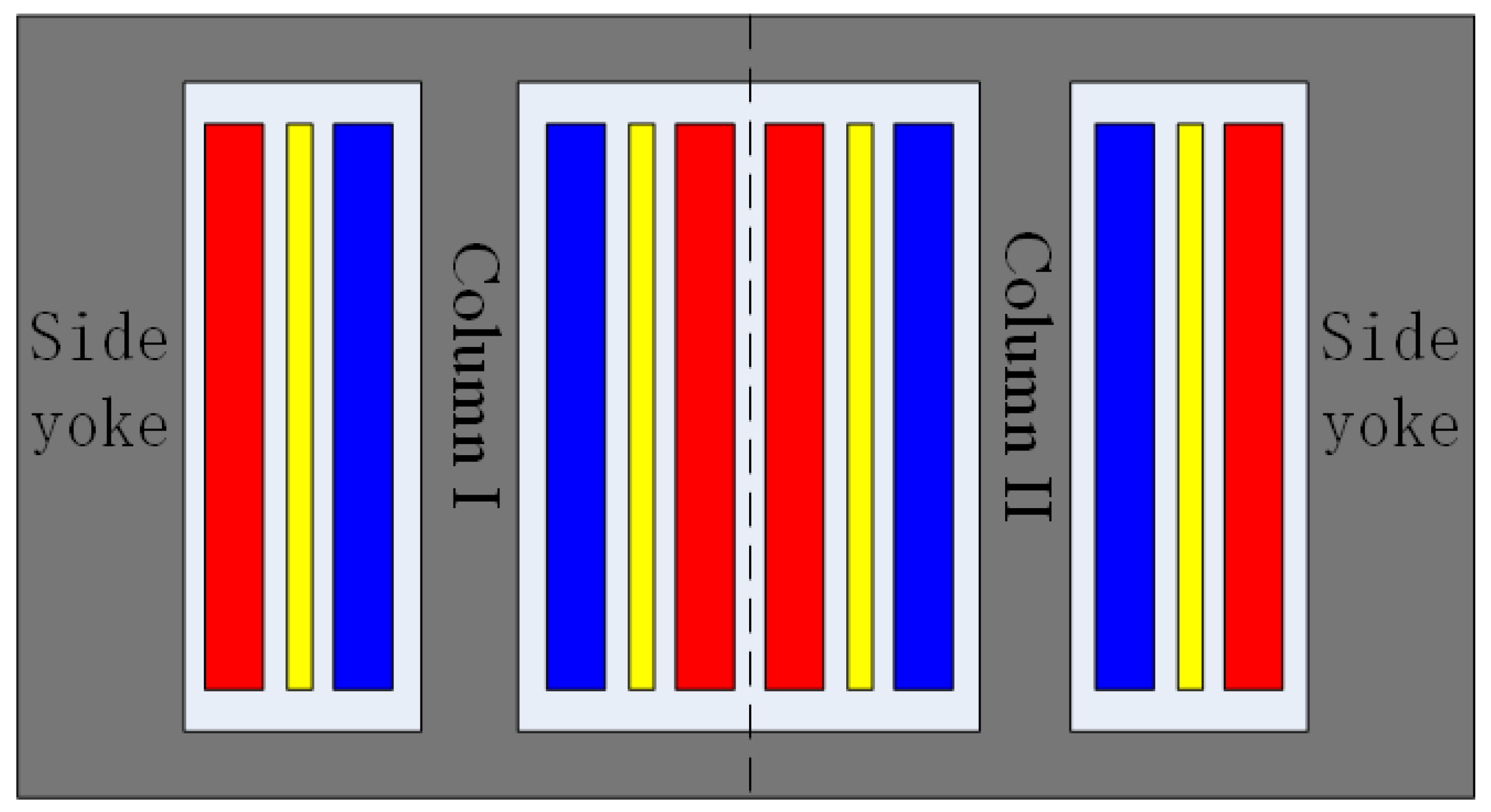
The novel converter transformer is mainly used in back-to-back converter stations. The converter transformer is generally divided into group structures for convenient transportation in HVDC. Therefore, the prototype of the small-capacity inductive filter converter transformer designed in the laboratory adopts a single-phase four-column structure, as shown in Figure 2. On this basis, the three-phase system is composed of three single-phase inductive filter converter transformers.
The iron core of the novel converter transformer has a single-phase dual-column yoke-type structure. There are three windings on the left and right core columns, which are the grid-side winding, filter-side winding, and valve-side winding, respectively. In Figure 2, the grid-side, valve-side, and filter-side windings are presented in red, yellow, and blue, and it can be seen that the distance between the three windings and the iron core decreases in turn. When a single-phase converter transformer is combined into a three-phase one and applied to a 12-pulse converter for DC transmission, the grid-side windings of the left column are star connected, the valve-side windings use the same connection method, and the filter-side winding adopts a delta connection. This is called a YYD connection structure. Similarly, a YDD connection structure means the windings of the grid side, valve side, and filter side of the right column adopt a star connection, delta connection, and delta connection, respectively. Figure 3 is an image of the physical wiring of the novel converter transformer.
Table 1 shows the specific parameters for the laboratory prototype of the single-phase novel converter transformer and Table 2 shows the corresponding structural parameters. To compare the characteristics, the field-circuit coupling finite element model of the converter transformer is modeled completely according to the actual parameters of the prototype. The grid-side windings are high-voltage windings, the valve-side windings are low voltage, and the windings of the filter side are medium-voltage windings. Accordingly, their distances from the iron core are consistent with those shown in Figure 2.

3.3. Finite Element Model of Converter Transformer

When using Ansoft for the physical modeling and finite element analysis of the novel converter transformer, to avoid the large calculations of the leakage of the magnetic field and electrodynamic force caused by the complex transformer structure and its many accessories, the transformer entity should be properly simplified as follows:
  • This paper focuses on the winding electromagnetic force and does not involve the research on the transformer’s eddy current loss. Therefore, the additional components, such as the transformer oil tank, bushing, and clamp, can be ignored in the modeling, whereas the physical model only considers the transformer core and winding;
  • The actual winding coil body includes wires, insulating materials, supporting parts, etc. When modeling the transformer winding coil, the solid layer is used to replace the winding coil body and the winding body is regarded as one. The winding structure and insulation between the sections are ignored but the supporting parts between the windings are retained.
In addition, the following assumptions are made in order to facilitate the analysis and calculations:
  • Ignore the influence of the displacement current and the conductivity of the metal conductor is set as a constant;
  • Assume that the total ampere turns of each winding are balanced and the current density in each sub-area of the winding is evenly distributed.
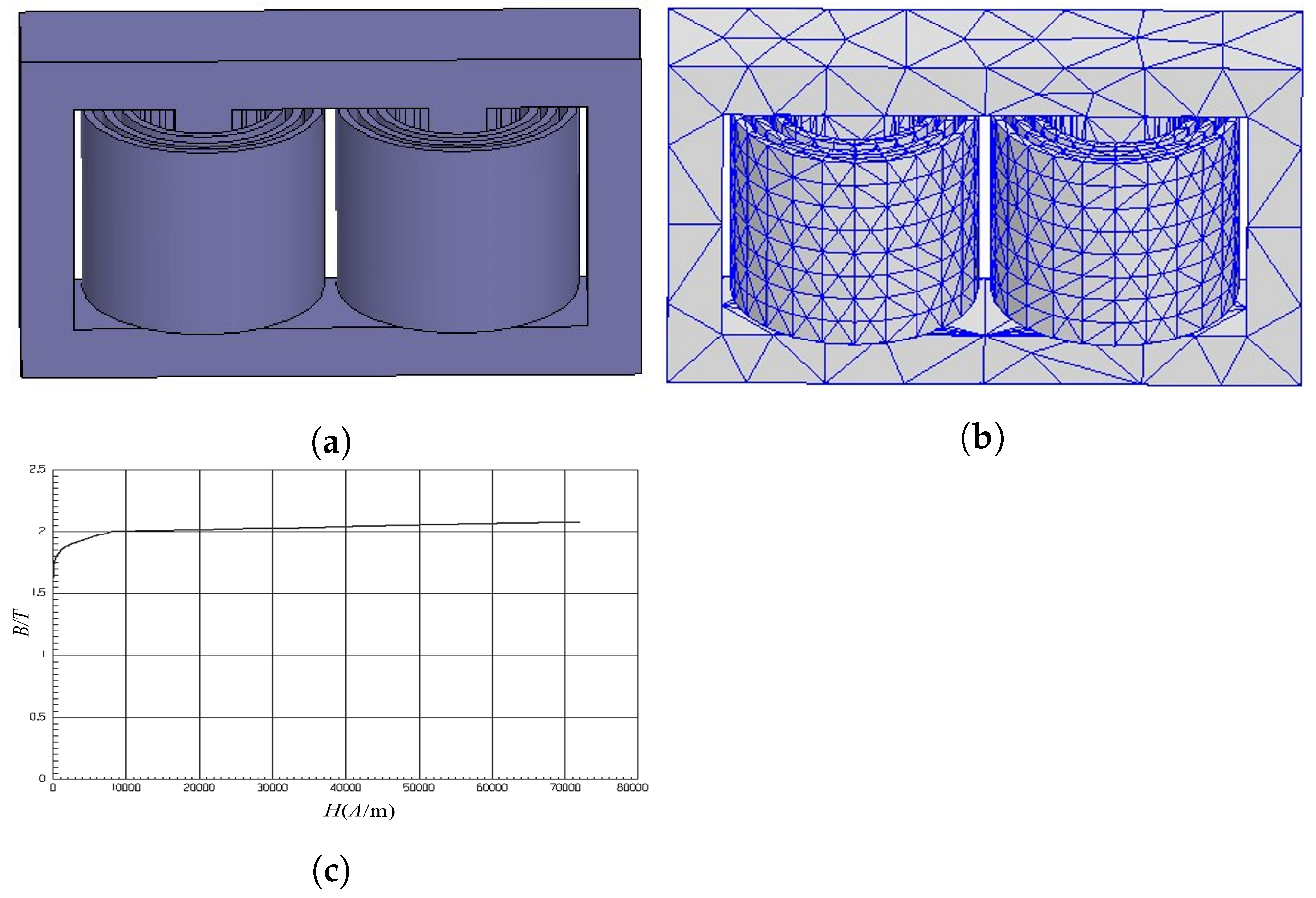
Next, the internal electromagnetic characteristics are analyzed and the magnetic field distribution and winding force of the converter transformer are calculated. According to the actual structural parameters and material parameters of the laboratory prototype combined with the model’s simplifications and assumptions discussed above, the 3D finite element geometric model of the single-phase converter transformer is established, as shown in Figure 4a.
In order to make the finite element calculation results more stable and realistic, tetrahedral elements are used to mesh the transformer model in this paper. The 3D FEM model of the split single-phase converter transformer is shown in Figure 4b. Figure 4c shows the magnetization characteristic curve of the silicon steel sheet used in the core modeling.

3.4. Field-Circuit Coupling Model

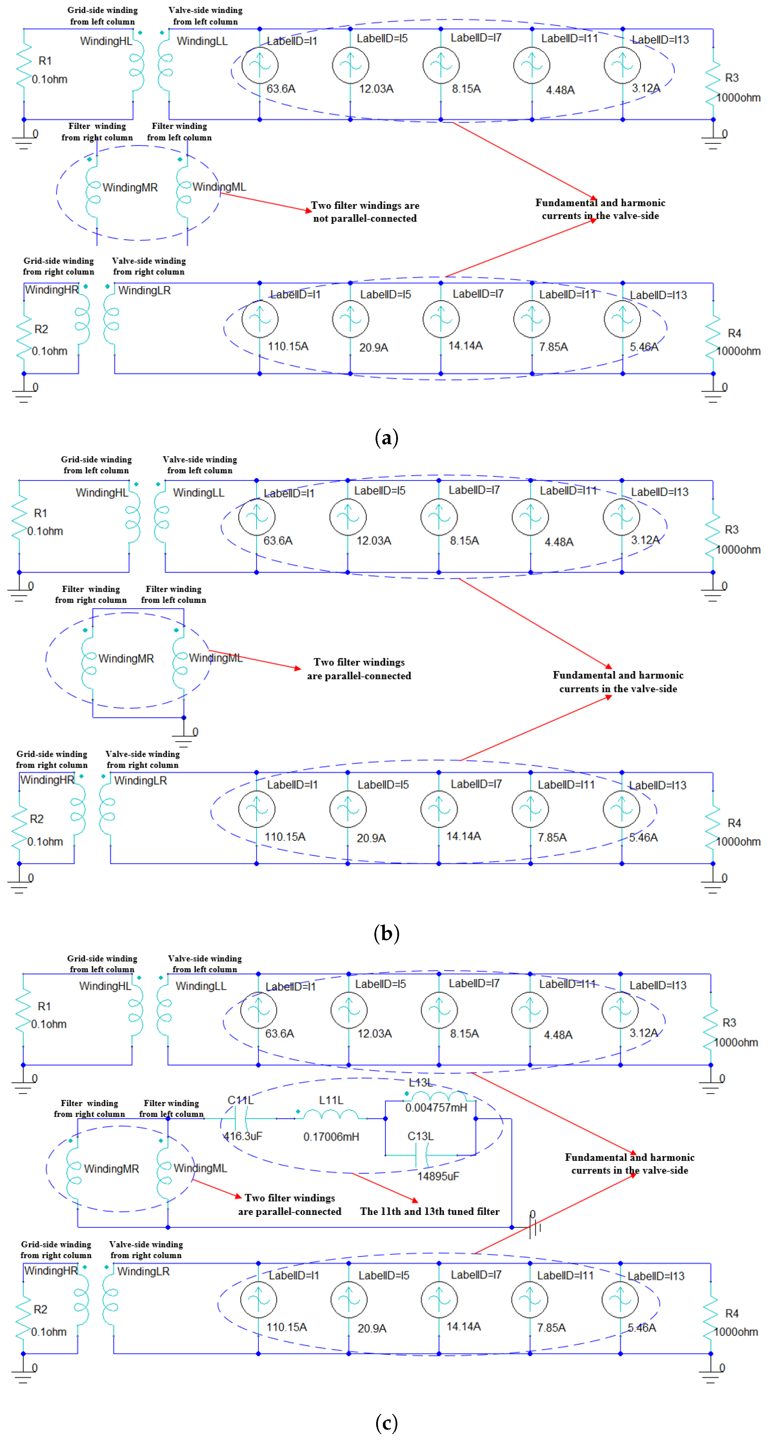
Based on the finite element model of the single-phase transformer established in Section 3.3, the field-circuit coupling models of the single-phase converter transformer under three working conditions are established, as shown in Figure 5. Working condition 1: two delta filter windings are not parallel-connected and the filters are not put into use. Working condition 2: two delta filter windings are parallel-connected and the filters are not put into use. Working condition 3: two delta filter windings are parallel-connected and the 11th and 13th filters are put into use.
In Figure 5, the tuned 11th and 13th filters are connected with the filter-side windings as an external circuit. The fundamental and harmonic currents are used as the excitation source to simulate the actual harmonic characteristics of the converter, which is connected with the valve-side winding of the converter transformer, and its values are shown in Table 3 and Table 4.

4. Electromagnetic Characteristic Analysis

4.1. Characteristics of Electric Field

In all figures in this section, red represents the data of the grid-side winding, blue denotes the data of the valve-side winding, and green represents the data of the filter-side winding. Figure 6, Figure 7 and Figure 8 show the current waveforms of the windings from the left and right columns of the converter transformer under three different working conditions, respectively. These figures fully verify the correctness of the finite element analysis model of the inductive filter converter transformer established by Ansoft and the corresponding field-circuit coupling model. Exporting the current waveform data of the grid-side winding from Ansoft to Matlab for FFT analysis, the current waveform spectrum of the left column grid-side winding of the novel converter transformer under three different working conditions, as shown in Figure 9, can be obtained. According to the analysis of Figure 6a and Figure 9a, when the two delta filter windings are not connected in parallel and the filter is not put into use, the harmonic current flows freely from the valve-side winding to the grid-side winding without any suppression. According to the analysis of Figure 7a and Figure 9b, under working condition 2, the 5th, 7th, and other n = 12 k 5 , 12 k 7 ( k = 1 , 2 , 3 , ) th harmonic currents on the valve side form a loop in two parallel filtering windings to prevent their transfer, and the current waveform of the grid-side winding is greatly improved, which is approximately sine wave. Based on the analysis of Figure 8a and Figure 9c, it can be seen that when the two delta filter windings are connected in parallel and connected with the 11th and 13th tuned filters, the main characteristic harmonic currents, such as the 5th, 7th, 11th, and 13th, are drained to the closed circuit composed of the filter-side winding and filter. In addition, the current waveform of the grid-side winding is a sine wave with a low distortion rate.
Based on the field-circuit coupling method, Figure 10, Figure 11 and Figure 12 show the voltage waveforms of grid-side, valve-side, and filter-side windings from the left and right columns of the novel converter transformer under three different working conditions, respectively.
As shown in Figure 10, under working condition 1, when the harmonic current generated by the converter valve flows freely to the grid side, the voltage waveforms of the grid-side and valve-side windings are seriously distorted, and the latter, in particular, have quite high spikes. In Figure 11, the n = 12 k 5 , 12 k 7 ( k = 1 , 2 , 3 , ) th harmonic current is suppressed due to the parallel-connected delta filter windings under working condition 2. Compared to condition 1, the voltage waveforms of the valve-side and grid-side windings have been improved and there is no high-spike wave in the voltage shape of the valve-side winding. It can be seen in Figure 12 that under working condition 3, the voltage waveforms of the three windings of the converter transformer have been further improved due to the suppression of the main characteristic harmonics such as the 5th, 7th, 11th, and 13th. Moreover, the voltage waveform of the winding on the grid side has become an approximate sine wave, the distortion degree of the voltage waveform on the valve side has been further reduced, and there is no spike wave. In summary, the following conclusions can be drawn. First, due to the implementation of inductive filtering, the harmonic current is effectively suppressed to avoid transferring. In addition, the electromagnetic coupling can effectively suppress the harmonic voltage on the transformer winding and it is difficult to form an overvoltage and inrush current, which are conducive to improving the operating environment and reducing the insulation difficulty of the converter transformer.

4.2. Magnetic Field Characteristics

In Figure 13, Figure 14 and Figure 15, according to the field-circuit coupling, the waveforms of the flux linkage on the grid-side, valve-side, and filter-side windings from the left and right columns of the novel converter transformer under three working conditions are displayed, respectively.
Comparing the flux characteristic curves of each winding under the three different working conditions, the flux distortion of the valve-side winding is serious due to the lack of inductive filtering in working condition 1. Then, because of the implementation of inductive filtering under working conditions 2 and 3, the flux linkage passing through each winding is closer to a sine wave. Therefore, the harmonic magnetic potential is effectively suppressed so the magnetic leakage around the transformer winding and core is decreased to reduce the harmonic magnetic leakage resistance and additional loss. The hysteresis loss of the transformer is caused by the repeated magnetization of the core in alternating magnetic fields and the harmonic magnetic potential is suppressed in working conditions 2 and 3, which significantly reduces the hysteresis loss of the transformer core in the high-frequency alternating magnetic field. At the same time, due to the suppression of the harmonic magnetic potential, the induced harmonic electromotive force component on the winding is greatly limited so the winding voltage will not produce a spike wave. Keeping the sinusoidal flux linkage is conducive to improving the internal electromagnetic environment of the converter transformer and reducing the insulation level of the winding.
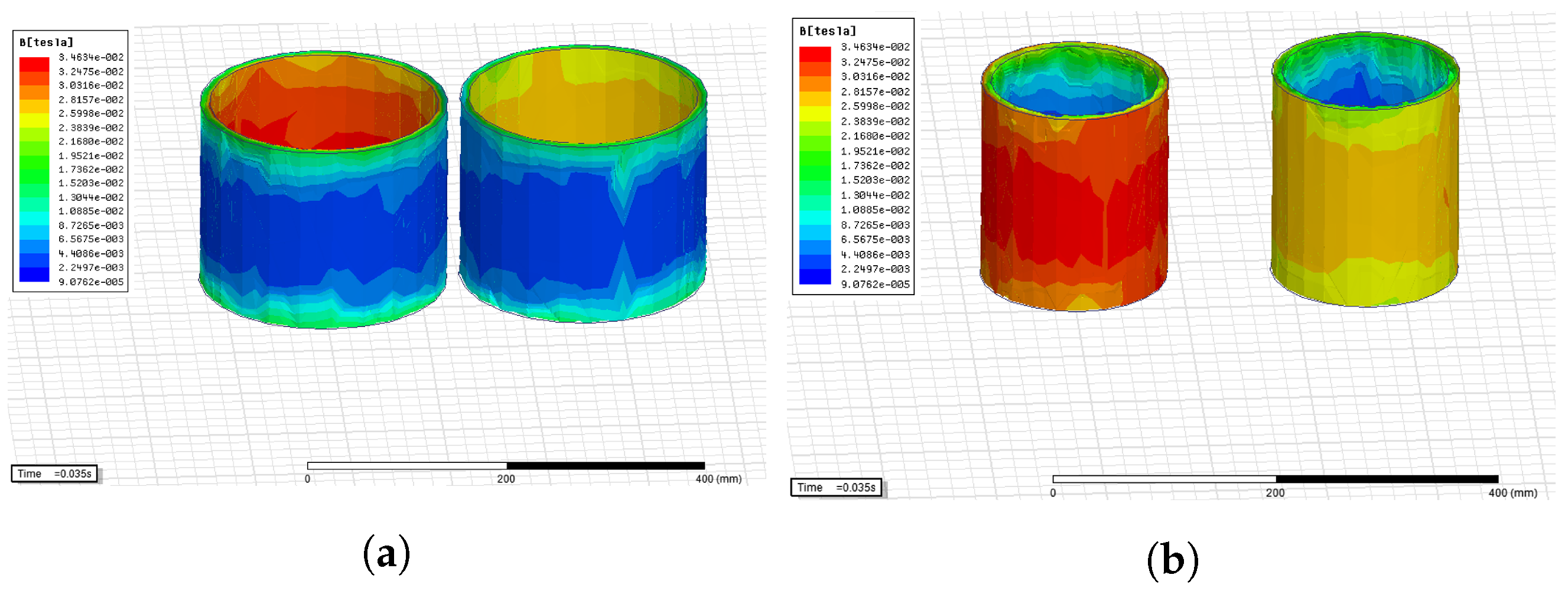
Figure 16, Figure 17 and Figure 18 show cloud diagrams of the magnetic density distribution for the grid-side and valve-side windings of the converter transformer under three different working conditions, respectively.
According to the comparative analysis of Figure 16, Figure 17 and Figure 18, the harmonic magnetic potential is effectively suppressed under conditions 2 and 3 due to the implementation of inductive filtering; thus, the magnetic density distribution of the grid-side and valve-side windings under the latter two working conditions is decreased. This helps to improve the internal electromagnetic environment of the transformer and reduce the insulation and vibration of the transformer winding.
To test the performance of the novel converter transformer under the three working conditions, the dynamic response curves of the electromagnetic force on the grid-side, valve-side, and filter-side windings from the left and right columns were determined and are displayed in Figure 19, Figure 20 and Figure 21.
By looking at Figure 19, Figure 20 and Figure 21, it can be seen that each winding of the inductive converter transformer is under a unidirectional force under any working condition and the pulsation frequency is twice the winding current frequency. Under conditions 2 and 3, there is little difference in the magnitude of the electromagnetic force on the grid-side windings but the high-frequency vibration component is greatly reduced. In addition, compared to working condition 1, the electromagnetic force on the grid-side windings of the transformer under other working conditions is significantly decreased. There are two main reasons for this phenomenon. From the perspective of harmonics, after the implementation of inductive filtering, the harmonic current is effectively suppressed so the electromagnetic force on each winding is suppressed, and the high-frequency component of the electromagnetic force on the winding is greatly reduced. In terms of the input filter, the filter is capacitive under the fundamental wave, which compensates for the fundamental wave current to a certain extent and increases the fundamental wave current on the winding. On this basis, the winding electromagnetic force increases to a certain extent. It can also be seen in the figures that under the latter two working conditions, the stress of the valve-side winding increases slightly compared to that under working condition 1. At the same time, it can be seen that the filter-side windings also bear a certain electromagnetic force but it is very small. In addition, the electromagnetic force on the grid-side winding is much greater than that on the valve-side and filter-side windings, which shows that the winding vibration of the converter transformer mainly comes from the grid-side windings.
Based on the field-circuit coupling method, the curves of the core losses characteristic under the three working conditions were determined and are presented in Figure 22.
According to Figure 22, it can be seen that the core losses under working condition 3 are significantly weakened compared with those under conditions 1 and 2, and the maximum value is reduced from 170 W to about 55 W. The core losses under working condition 2 are also slightly reduced. The reason for the above phenomenon is that the inductive filtering technology is implemented in working condition 3, which can effectively suppress the 5th, 7th, 11th, and 13th harmonic currents. Therefore, the harmonic current cannot be transferred to the grid side so the harmonic magnetic flux and power loss in the core are suppressed and significantly reduced.

5. Conclusions

By using Ansoft, the single-phase 3D FEM model of the converter transformer was first established according to its structural parameters and material characteristics. Then, the external circuit connection based on the 3D FEM model was realized and the field-circuit coupling model was established. On this basis, the electric field characteristics, magnetic field characteristics, winding electromagnetic force characteristics, and core loss characteristics of the converter transformer were analyzed. The research on the internal electromagnetic characteristics of the converter transformer laid the foundation for revealing the mechanism of reducing the vibration and noise of the converter transformer. The conclusions from the analysis of the experimental results are as follows:
  • When two delta filter windings were connected in parallel regardless of whether the filter was connected or not, the implementation of inductive filtering could effectively suppress the harmonic current and make the flux linkage passing through each winding of the inductive filtering converter transformer increasingly closer to a sine wave. On this basis, the harmonic magnetic potential was also effectively suppressed, which significantly reduced the hysteresis loss of the core in the high-frequency alternating magnetic field. In addition, the induced harmonic electromotive force component on the winding was greatly reduced so that the winding voltage would not produce a spike wave.
  • Compared to the structure without the parallel connection of the delta filter windings and the usage of filters, in all cases, the parallel structure not only significantly reduced the electromagnetic force on each winding of the inductive converter transformer but also greatly weakened the high-frequency vibration component. At the same time, the core loss of the converter transformer was also significantly decreased.

Author Contributions

Conceptualization, J.L. (Jianying Li) and J.W.; Data curation, J.L. (Jianying Li), Y.Z., J.W., and X.X.; Formal analysis, J.L. (Jianying Li) and M.Y.; Funding acquisition, J.L. (Jianying Li), Y.Z., and J.L. (Jianqi Li); Investigation, J.L. (Jianying Li), Y.Z., and J.W.; Methodology, J.L. (Jianying Li), M.Y., and X.X.; Software, J.L. (Jianying Li); Writing—original draft, J.L. (Jianying Li); Writing—review and editing, J.L. (Jianying Li), J.L. (Jianqi Li), M.Y., and X.X. All authors have read and agreed to the published version of the manuscript.

Funding

This research was funded by the National Natural Science Foundation of China (Grant No. 62273142); the Program of the Natural Science Foundation of Hunan Province (Grant No. 2021JJ30477 and 2021JJ50023); the Hunan Enterprise Science and Technology Commissioner program (Grant No. 2021GK5074); the science and technology innovation program of Hunan Province (Grant No. 2021GK2010); the Research Foundation of the Education Bureau of Hunan Province, China (Grant No. B08007054 and 22A0490); and the scientific research project of the Hunan University of Arts and Sciences (Grant No. 17BSQD29).

Conflicts of Interest

The authors declare no conflict of interest.

References

  1. Luo, L.; Li, Y.; Xu, J.; Li, J.; Hu, B.; Liu, F. A new converter transformer and a corresponding inductive filtering method for HVDC transmission system. IEEE Trans. Power Deliv. 2008, 23, 1426–1431. [Google Scholar] [CrossRef]
  2. Li, Y.; Luo, L.; Rehtanz, C.; Ruberg, S.; Yang, D.; Xu, J. An industrial DC power supply system based on an inductive filtering method. IEEE Trans. Ind. Electron. 2011, 59, 714–722. [Google Scholar] [CrossRef]
  3. Liu, Q.; Li, Y.; Hu, S.; Luo, L. Power quality improvement using controllable inductive power filtering method for industrial DC supply system. Control Eng. Pract. 2019, 83, 1–10. [Google Scholar] [CrossRef]
  4. Liu, Q.; Li, Y. An inductive filtering-based parallel operating transformer with shared filter for power quality improvement of wind farm. IEEE Trans. Power Electron. 2020, 35, 9281–9290. [Google Scholar] [CrossRef]
  5. Liu, Q.; Li, Y.; Hu, S.; Luo, L. A controllable inductive power filtering system: Modeling, analysis and control design. Int. J. Electr. Power Energy Syst. 2019, 105, 717–728. [Google Scholar] [CrossRef]
  6. Liu, Q.; Li, Y.; Hu, S.; Luo, L. A Transformer Integrated Filtering System for Power Quality Improvement of Industrial DC Supply System. IEEE Trans. Ind. Electron. 2019, 67, 3329–3339. [Google Scholar] [CrossRef]
  7. Liu, Q.; Li, Y.; Hu, S.; Luo, L.; Cao, Y. Study on Filtering Mechanism and Operating Characteristic of the Controllably Inductive Power Filtering System. Diangong Jishu Xuebao/Trans. China Electrotech. Soc. 2018, 33, 3274–3283. [Google Scholar]
  8. Li, Y.; Peng, Y.; Liu, F.; Sidorov, D.; Panasetsky, D.; Liang, C.; Luo, L.; Cao, Y. A Controllably Inductive Filtering Method with Transformer-Integrated Linear Reactor for Power Quality Improvement of Shipboard Power System. IEEE Trans. Power Deliv. 2017, 32, 1817–1827. [Google Scholar] [CrossRef]
  9. Tian, Y.; Luo, L.F.; Li, Y.; Huang, Z.; Liu, Q.Y. Performance Analysis and Port Matrix Model of 220kV Multi-winding Inductively Filtered Transformer. Proc. CSEE 2020, 40, 3042–3051. [Google Scholar]
  10. Huang, Z.; Luo, L.F.; Li, Y.; Shi, S.M.; Tian, Y. Research the Operating Characteristics of Four-winding Inductive Filtering Transformer Based on the Port Model. Proc. CSEE 2019, 39, 6706–6715. [Google Scholar]
  11. Ning, Z.; Luo, L.; Li, Y.; Zhang, Z.; Rehtanz, C.; Zhang, J.; Zhao, Z. Analysis and synthesis energy saving design of large power rectifier system based on inductive filtering technology. Diangong Jishu Xuebao Trans. China Electrotech. Soc. 2012, 27, 223–228. [Google Scholar]
  12. Li, J.Y.; Luo, L.F.; Xu, J.Z.; Zeng, J.H. Novel Rectifier System Using Harmonic Suppression Rectifier Transformer. Gaodianya Jishu/High Volt. Eng. 2011, 37, 3164–3170. [Google Scholar]
  13. Li, J.; Luo, L.; Xu, J. A Harmonic Suppression Rectifier Transformer with Filters for an Industrial Rectifier System. Recent Adv. Electr. Electron. Eng. 2014, 7, 65–74. [Google Scholar]
  14. Li, Y.; Luo, L.; Rehtanz, C.; Nakamura, K.; Xu, J.; Liu, F. Study on Characteristic Parameters of a New Converter Transformer for HVDC Systems. IEEE Trans. Power Deliv. 2009, 24, 2125–2131. [Google Scholar]
  15. Li, J.; Xiao, Y.; Yang, M.; Li, J.; Wan, J. The Research on Harmonic Transfer Characteristics of Integrated Multi-Winding Inductive Filtering Converter Transformer and Its Filter System. Electronics 2022, 11, 2088. [Google Scholar] [CrossRef]
  16. Xu, J.Z.; Luo, L.F.; Li, J. Shielding Windings Analysis of Large Current Transformers Based on Coupled Field-circuit Method. Proc. CSEE 2006, 26, 167–172. [Google Scholar]
  17. Xie, B.R.; Chen, Q.F.; Kang, C.H.; Wang, H.J. Modeling and impedance parameter design for multi-winding transformer based on combined field-circuit coupled method. Proc. CSEE 2009, 29, 104–111. [Google Scholar]
  18. Ostrenko, M.; Andriienko, B. Transformer Impulse Surges Calculation by FEM Coupled to Circuit. IEEE Trans. Magn. 2017, 53, 7401804. [Google Scholar] [CrossRef]
  19. Wu, J.; Wang, J.; Gan, C.; Sun, Q.; Kong, W. Efficiency Optimization of PMSM Drives Using Field-Circuit Coupled FEM for EV/HEV Applications. IEEE Access 2018, 6, 15192–15201. [Google Scholar] [CrossRef]
  20. Huangfu, Y.; Wang, S.; Qiu, J.; Zhang, H.; Wang, G.; Zhu, J. Transient Performance Analysis of Induction Motor Using Field-Circuit Coupled Finite-Element Method. IEEE Trans. Magn. 2014, 50, 873–876. [Google Scholar] [CrossRef]
  21. Pan, C.; Mi, J.; Wang, G.; Cai, G.; Zhang, Y. Electromagnetic Harmonic Response Analysis Method of Inter-Turn Short Circuit in Transformer Winding Based on Field Circuit Coupling. Trans. China Electrotech. Soc. 2019, 34, 673–682. [Google Scholar]
  22. Duan, X.; Tong, Z.; Liu, J.; Li, Z.; Liang, Z. Analysis of Winding Vibration Characteristics of Power Transformers Based on the Finite-Element Method. Energies 2018, 11, 2404. [Google Scholar] [CrossRef] [Green Version]
  23. Li, L.; Liu, X.; Zhu, G.; Chen, H.; Gao, S. Research of Short-Circuit Performance of a Split-Winding Transformer with Stabilizing Windings. IEEE Trans. Appl. Supercond. 2019, 29, 0601106. [Google Scholar] [CrossRef]
  24. Kang, Y.; Bai, B.; Guo, Y. Application of Field-Circuit Coupling Method of 3D Transient Finite Element Analysis for Large Power Transformers. Diangong Jishu Xuebao/Trans. China Electrotech. Soc. 2014, 29, 218–224. [Google Scholar]
  25. Park, K.H.; Lee, H.J.; Hahn, S.C. Finite-Element Modeling and Experimental Verification of Stray-Loss Reduction in Power Transformer Tank with Wall Shunt. IEEE Trans. Magn. 2019, 55, 7502104. [Google Scholar] [CrossRef]
Figure 1. Ansoft Maxwell 3D electromagnetic field solution flow chart.
Electronics 12 00227 g001
Figure 2. Structural model of single-phase transformer.
Electronics 12 00227 g002
Figure 3. Structural model of single-phase transformer.
Electronics 12 00227 g003
Figure 4. Finite element model of single-phase converter transformer. (a) Geometric model. (b) Subdivision model. (c) Magnetization curve of silicon steel sheet.
Electronics 12 00227 g004
Figure 5. Field-circuit coupling models under three different working conditions. (a) Working condition 1. (b) Working condition 2. (c) Working condition 3.
Electronics 12 00227 g005
Figure 6. Current waveforms of grid-side and valve-side windings under working condition 1. (a) The left column. (b) The right column.
Electronics 12 00227 g006
Figure 7. Current waveforms of grid-side and valve-side windings under working condition 2. (a) The left column. (b) The right column.
Electronics 12 00227 g007
Figure 8. Current waveforms of grid-side and valve-side windings under working condition 3. (a) The left column. (b) The right column.
Electronics 12 00227 g008
Figure 9. Current waveform spectra for grid-side winding from the left column under three working conditions. (a) Working condition 1. (b) Working condition 2. (c) Working condition 3.
Electronics 12 00227 g009
Figure 10. Voltage waveforms from grid-side and valve-side windings under working condition 1. (a) The left column. (b) The right column.
Electronics 12 00227 g010
Figure 11. Voltage waveforms from the three windings under working condition 2. (a) The left column. (b) The right column.
Electronics 12 00227 g011
Figure 12. Voltage waveforms from the three windings under working condition 3. (a) The left column. (b) The right column.
Electronics 12 00227 g012
Figure 13. Waveforms of flux linkage from grid-side and valve-side windings under working condition 1. (a) The left column. (b) The right column.
Electronics 12 00227 g013
Figure 14. Waveforms of flux linkage from the three windings under working condition 2. (a) The left column. (b) The right column.
Electronics 12 00227 g014
Figure 15. Waveforms of flux linkage from the three windings under working condition 3. (a) The left column. (b) The right column.
Electronics 12 00227 g015
Figure 16. Cloud diagrams of the magnetic density distribution for the grid-side and valve-side windings under working condition 1. (a) Grid-side windings. (b) Valve-side windings.
Electronics 12 00227 g016
Figure 17. Cloud diagrams of the magnetic density distribution for the three windings under working condition 2. (a) Grid-side windings. (b) Valve-side windings. (c) Filter-side windings.
Electronics 12 00227 g017
Figure 18. Cloud diagrams of the magnetic density distribution for the three windings under working condition 3. (a) Grid-side windings. (b) Valve-side windings. (c) Filter-side windings.
Electronics 12 00227 g018
Figure 19. Dynamic response curves of electromagnetic force on each winding under working condition 1. (a) The left column. (b) The right column.
Electronics 12 00227 g019
Figure 20. Dynamic response curves of electromagnetic force on each winding under working condition 2. (a) The left column. (b) The right column.
Electronics 12 00227 g020
Figure 21. Dynamic response curves of electromagnetic force on each winding under working condition 3. (a) The left column. (b) The right column.
Electronics 12 00227 g021
Figure 22. Curves of core loss characteristics under the three working conditions. (a) Working condition 1. (b) Working condition 2. (c) Working condition 3.
Electronics 12 00227 g022
Table 1. Parameters of single-phase converter transformer prototype.
Rated parametersCapacity20 kVA
Voltage (grid side/filter side/
Y-connection on the valve side)
219.39/380/219.38 V
Voltage (grid side/filter side/
Δ -connection on the valve side)
19.39/380/380 V
(grid side/filter side/
Y-connection on the valve side )
91.16/21.05/91.16 A
Current (grid side/filter side/
Δ -connection on the valve side)
91.16/21.05/52.63 A
Frequency50 Hz
Phase numberOne
CoreMaterial30Q140
Magnetic density1.5204 T
Diameter130 mm
windingtypeConcentric
Table 2. Structural parameters of converter transformer model.
ComponentParameter/MMComponentParameter/MM
CoreLength/width/
height
645/127/360High-voltage
winding on
the left side
Inner/outer
diameter
117/126.5
Thickness
of iron yoke
55Height197
Center distance
of core column
265Height of
end insulation
11.5
Lamination of core11Low-voltage
winding on
the right side
Inner/outer diameter76/85.5
Low-voltage
winding on
the left side
Inner/outer diameter76/85.5Height197
Height192Height of
end insulation
11.5
Height of end insulation14Intermediate-
voltage
winding on
the right side
Inner/outer diameter95.5/105
Intermediate-voltage
winding on
the left side
Inner/outer diameter95.5/105Height192
Height192Height of
end insulation
14
Height of end
insulation
14High-voltage
winding on
the right side
Inner/outer diameter117/126.5
BraceHeight210Height197
Quantity of inner/
middle/outer
2004/10/12Height of
end insulation
11.5
Table 3. Current values from each winding at phase A under the rated operation of the inductive filter converter transformer with the YYD structure.
Sampling PositionNumber of Fundamental or Harmonic1571113Effective Value of Fundamental
Grid sideAmplitude/A109.810.550.410.340.2177.64
Phase angle/°4.7139.4254.440.9185
Value sideAmplitude/A63.612.038.154.483.1244.97
Phase angle/°−13.1−65.7267.9212.1188.8
Filter sideAmplitude/A19.812.327.924.68314
Phase angle/°86.9114.988.332.49
Table 4. Current values from each winding at phase A under the rated operation of the inductive filter converter transformer with the YDD structure.
Sampling PositionNumber of Fundamental or Harmonic1571113Effective Value of Fundamental
Grid sideAmplitude/A109.810.550.410.340.2177.64
Phase angle/°4.7139.4254.440.9185
Value sideAmplitude/A63.612.038.154.483.1244.97
Phase angle/°−13.1−65.7267.9212.1188.8
Filter sideAmplitude/A19.812.327.924.68314
Phase angle/°86.9114.988.332.49
Disclaimer/Publisher’s Note: The statements, opinions and data contained in all publications are solely those of the individual author(s) and contributor(s) and not of MDPI and/or the editor(s). MDPI and/or the editor(s) disclaim responsibility for any injury to people or property resulting from any ideas, methods, instructions or products referred to in the content.