Abstract
High-band allocations in the millimeter-wave (mm-Wave) frequency spectrum offer high-capacity wireless information transmission as required by fifth generation (5G) communication standards. Among different beamforming structures, the Rotman lens (RL) is an attractive passive-microwave-lens-based beamforming network due to its low fabrication cost, reliability, design simplicity and wide-angle scanning capabilities. Conventionally, the RL is implemented using microstrip line (MSL) technology for which there are inherent radiation losses that become severe when operating in mm-Wave 5G frequency bands. In this context, a novel substrate-integrated coaxial line (SICL)-based RL is designed, fabricated and tested, for accurate beamforming with extremely low feed line insertion loss. This article presents a complete design, development and performance analysis of an SICL-based RL beamformer. By using an SICL, isolation of up to 15 dB is achieved between the input beam ports of the RL, while the mutual coupling is kept at less than 20 dB. The SICL design shows a −10 dB insertion loss between the array and beam ports when compared to the same RL developed using MSL technology having an insertion loss of −15 dB. Due to the use of low-loss SICL technology, a realized gain of up to 14.2 dBi is achieved with an excellent scanning capability of −30 to 30 degrees, verifying for the first time the beamforming capabilities associated with SICL technology. The operational frequency band is 20–45 GHz, while the center operating frequency is 26 GHz making it appropriate for above 6-GHz 5G New Radio (NR) operating bands n257 (26.5 GHz to 29.5 GHz), n258 (24.25 GHz to 27.5 GHz), n261 (27.5 GHz to 28.35 GHz) and n260 (37 GHz to 40 GHz). Owing to the low-loss and stable beamforming performance, the SICL RL is suitable for mm-Wave 5G and is extendable to B5G applications.
1. Introduction
During the last few decades, information and communications technology (ICT) is experiencing rapid growth. Recently, the lockdown during the COVID-19 pandemic significantly increased the internet traffic demands of residential users, in particular, for remote working, entertainment, commerce and education []. Applications such as live HD video streaming for law enforcement during emergencies, Internet of Things (IoT)-based healthcare systems for the remote care of patients, beacon-based systems for enhanced marketing in the retail industry, etc., require high-data-rate wireless connectivity with acceptable reliability. Recent studies found that data traffic is expected to experience a 1000-fold capacity increase in the coming decade []. To meet this capacity demand, the millimeter-wave (mm-Wave) frequency band ranging from 3 GHz to 300 GHz is currently being explored [].
The spectrum below 6 GHz is majorly congested due to several existing wireless standards []. To meet the demands of the increased data rates, 5G communication has had to migrate toward the mm-Wave spectrum. Consequently, the 3rd Generation Partnership Project (3GPP) developed 5G New Radio (NR) standards for the usage of different frequency bands including 450 to 960 MHz, 3 to 6 GHz, 24.25 to 52.6 GHz and 66 to 86 GHz []. Above 6 GHz, the first band in 5G resides close to the 25.5 to 27 GHz band which provides sufficient bandwidth for 5G applications []. Wireless transmission at such high frequencies becomes challenging due to inherent free space path losses, high penetration losses and other atmospheric losses []. To overcome these, highly directional transmission is necessary for which multi-beam antennas with efficient beamforming networks (BFNs) are required. The Rotman lens (RL) is an attractive passive-microwave-lens-based BFN that has attractive properties such as reliability, structural/operational simplicity and wide tailorable beam scanning ranges [].
Microwave lenses were first introduced in the 1950s, the earliest known being the Ruze lens []. Rotman and Turner used this concept to introduce the Rotman lens in the 1960s []. A trifocal-lens-based BFN was designed that shows improved phase error performance than bootlace and Ruze lenses. Since then, the Rotman lens has been used for studies, improvements and modifications for specific applications. Major improvements such as an increasing scanning angle [,,], miniaturization [], accurate phase distribution [] and less coupling between ports [] are reported in recent research studies.
In the BFN literature, a significant amount of work on designing RLs using microstrip lines is reported for a variety of applications. A comparatively lower number but still significant number of studies discuss RL development using planar technologies such as substrate-integrated waveguides (SIWs) [], slot lines, etc. []. At the mm-Wave frequency range, realizing communication system radio hardware using conventional planar technologies for commercial use becomes a challenging task due to their inherent insertion losses []. For mm-Wave frequencies, such technologies suffer from radiation losses, conductor losses, dielectric losses and spillover losses []. The path loss at these high frequencies also becomes comparatively high due to a very low wavelength. Additionally, the mutual coupling between ports also presents serious issues.
Coaxial line technology, although non-planar in nature, is a non-dispersive and shielded transmission line technology, which makes it an attractive candidate for mm-Wave radio hardware realization. However, its non-planar nature makes it difficult to integrate with other planar structures. To resolve this, a planar form of coaxial line topology known as a substrate-integrated coaxial line (SICL) was introduced by Gatti []. In addition to the merits similar to the SIW, the SICL exhibits a wide operating bandwidth with a non-dispersive transverse electric and magnetic (TEM) field mode as well as easy integration with other planar circuits. A number of studies based on the SICL include its deployment in filters [,], couplers [,] and antennas [,]. The SICL is displayed to be used for achieving high-data-rate signal transmission, as expected to be a key requirement for 5G and beyond 5G (B5G) applications. A 15 × 3 channel SICL array example prototype is shown in []. The SICL also provides features such as low insertion loss, low radiation loss, wide stopband [] and low crosstalk at higher frequencies [] while supporting high-data-rate signal transmission.
In this work, a low-loss RL-based beamforming network was developed using SICL technology. A 5 × 8 RL was initially designed using the conventional microstrip line (MSL) technology, and then the same design was implemented using SICL technology. The insertion loss of both designs was quantified and compared. The SICL technology achieved low insertion losses of up to −10 dB over a wide frequency band of 20–45 GHz as compared to the same design with the MSL having −15 dB insertion losses. The SICL RL was then integrated with a 1 × 8 antenna array to develop a BFN that has steering capabilities of up to ±30 degrees.
2. Theoretical Analysis and Design Evolution
An RL is a multiport microwave circuit whose design is based on optical theory. The lens consists of input ports known as beam ports from which electromagnetic (EM) energy is fed. The lens cavity is a parallel-plate region that provides a phase shift to the input signal and forwards it to the receiving ports also known as array ports []. The lens is constructed by determining the location of beam ports and array ports and the length of the transmission line connecting array ports to the antenna array [].
2.1. Theoretical Background
A trifocal schematic design of the RL along with an antenna array is shown in Figure 1a. Three focal points F0, F1 and F2 are located on the circular focal arc also known as beam contour B. F1 and F2 are located symmetrically at the focal angle of α from the origin O. Each of these focal points produces a linear phase shift for the array to steer the beam into any known direction at a scanning angle of ψ. The ratio between F2 and F1 is known as a focal ratio and is expressed through the letter β. G is located at the center of the focal arc. The relative permittivity of the lens cavity and transmission line is and , respectively. In the design, the electrical length of transmission lines TL and point A (xA, yA) on the inner lens contour are the unknowns. The length of the transmission line connecting the inner array contour and the outer array contour is obtained using the fundamental level work by Rotman []. For any desired application, the values of ψ, α and β can be optimized which control the contours and the overall structure of the RL.
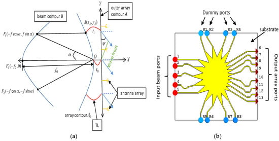
Figure 1.
(a) Typical Rotman lens contours; (b) Rotman lens design with 5 input beam ports and 8 output array ports.
2.2. Microstrip-Line-Based RL
The first step in designing an RL is to specify the operating frequency. As discussed earlier, the wide band above 6 GHz, i.e., 20–45 GHz, is chosen for this study with an operating center frequency of 26 GHz. With minimum path error and optical aberrations, the final parameters of the RL design are the scanning angle and focal angle for the focal ratio. The number of beam and array ports is selected to be five input ports and eight output ports, respectively, such that beam and array contours are of the same height for minimum sidewall reflections. As shown in Figure 1b, four dummy ports with 50 Ω terminations on each sidewall, denoted by R1-R8, are also added to absorb these sidewall reflections. Here, a Rogers RO4003C substrate of 0.406 mm thickness is used for the design. Tapers of 2λ length are then designed on the ports to minimize mismatch and reflections between the ports [,]. The taper angle and aperture width are optimized to minimize the reflections accordingly. The array contour has an inherent curvature due to which it is difficult to mount the connectors. For this purpose, the transmission lines are designed at the center frequency of 26 GHz which phase-align the output array ports for further integration with the antenna array. As the characteristic impedance Zo remains constant, i.e., 50 Ω, the width of the transmission lines would remain unchanged (in this case, 0.908 mm). However, the length of the transmission lines is optimized for perfect phase alignment and the lowest insertion loss [].
2.3. SICL-Based RL
After designing an RL using an MSL, an SICL is implemented on the same design for direct comparison. The SICL is a planar coaxial transmission line that can easily be integrated with dielectric substrates. The structure consists of a feeding conductor sandwiched between two grounded dielectric layers as shown in Figure 2. The via holes are developed along the two sides of the transmission line. This via “wall” limits the feeding conductor and provides lateral shielding to avoid a parallel-plate mode which could cause leakage and interference with other lines [].
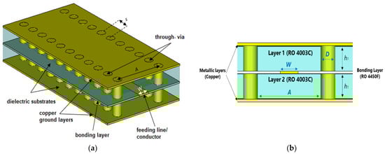
Figure 2.
Designed Substrate-Integrated Coaxial Line (SICL). (a) Top-view diagram; (b) side-view diagram.
2.3.1. Designing an SICL line
Before implementing the SICL technology on an RL, a SICL line is designed and optimized at the center frequency of 26 GHz. Like a coaxial line, the SICL allows quasi-TEM mode propagation having the TE10 mode as its first upper mode. The cut-off frequency of the SICL is the same as that of an SIW line as the inner conductor does not affect the model field structure (for further details on this concept, see []). The cut-off frequency of the first mode is given as
where d is the diameter of through vias in the structure, s represents the separation between vias, and A is the distance between two rows of vias. The diameter (d) of the via typically should be kept within one fifth of the guided wavelength, and the pitch (s) should be selected less than twice the diameter of the via such that the via wall is able to guide the electromagnetic wave through the line.
The SICL line is designed for unimodal operation of up to 26 GHz. The feeding line is sandwiched between two layers of the low-loss Rogers 4003C substrate of an equal height h1 of 0.406 mm having the dielectric constant of 3.55 as shown in Figure 2. The diameter of the via holes is chosen as 0.7 mm and the separation between two holes as 1.2 mm according to the technological constraints for ease of fabrication. The unimodal bandwidth of the line is controlled by adjusting the distance between two rows of vias A by using Equation (1). The width of the inner feeding line W is optimized to achieve a characteristic impedance of Zo = 50 Ω as the characteristic impedance of the SICL is a function of substrate thickness to the width of the inner conductor () ratio.
As shown in Figure 3a, the gap between the two substrates is introduced because of the width of the inner conductor layer which permits the field to propagate between the inner layer and the grounded vias. This reduces the fields propagating from input beam ports to output array ports, i.e., transmission coefficients are reduced at the resonating frequency of 26 GHz. Figure 3b illustrates the electric field leakage due to the introduced gap between two layers. The bonding layer of Rogers 4450B is used in the design to fill the gap providing additional structural rigidity.
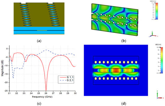
Figure 3.
(a) Introduced gap between two dielectric layers; (b) E-fields at cutting plane to show leakages inside the gap; (c) S-parameters of the optimized SICL line; (d) the magnitude of electric field current distribution of the designed SICL line at 26 GHz frequency.
The SICL line is optimized and S-parameters are obtained with a low reflection coefficient of −24 dB (transmission coefficient of −0.05 dB) at the operating frequency of 26 GHz as shown in Figure 3c. The SICL line is also designed and simulated using empty via holes. However, no significant difference in the S-parameters is found between both filled and empty via-hole cases. The magnitude of the electric field of the designed SICL line is shown in Figure 3d which proves that the electric field is propagating efficiently between the ports with very low leakage from the SICL via holes.
2.3.2. SICL Technology
Once the SICL line is designed, the optimized values are then used to design the SICL-based RL BFN. The RL designed using the method discussed earlier is sandwiched between two grounded substrate layers. The bond layer of RO4450B of thickness 0.101 mm is placed in between the two substrates to avoid reflections and to provide the required structural rigidity. After designing the RL using SICL technology, the layered structure, shown in Figure 4, is simulated and then compared with the same design in the MSL.
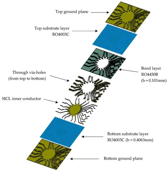
Figure 4.
Layer layout view of the designed SICL Rotman Lens.
In the SICL, the design is sandwiched between two substrate layers which significantly improves the reflection coefficients (at some frequencies up to 15 dB) at the input ports. The simulated insertion losses of the designed RL are compared in Figure 5. Using the SICL, the insertion losses are improved by up to 5 dB as compared with the design of the MSL RL, which means a good transmission of EM energy from the input beam ports to the output array ports. A progressive phase shift is achieved at the output array ports when input beam ports are excited sequentially as can be seen in Figure 6. It can be seen that due to the phase alignment of the transmission lines connecting the connectors to the RL structure, the designed SICL RL shows a phase-aligned distribution across the output array ports.
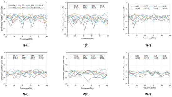
Figure 5.
Simulated insertion losses of (1) SICL- and (2) MSL-based RL at array ports when (a) beam port 1 is excited, (b) beam port 2 is excited, and (c) beam port 3 is excited.
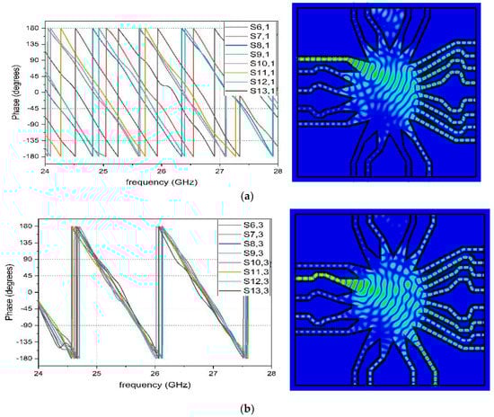
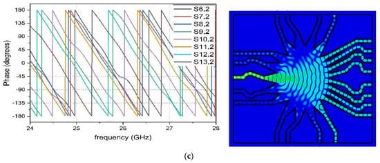
Figure 6.
S-parameters of SICL-based RL at array ports showing linear progressive phase distributions along with electric field distributions when (a) beam port 1 is excited, (b) beam port 2 is excited, and (c) beam port 3 is excited at frequency of 26 GHz.
The current distribution diagrams in Figure 6 highlight a smooth distribution of EM energy across the array ports when beam ports 1, 2 and 3 are excited sequentially. As noted earlier in a single SICL line, the SICL-based RL demonstrates a very low radiation loss along the feed line side walls due to its inherent structure sandwiching the design in two substrate layers. The reflection coefficient of both designs is shown in Figure 7a,b. It can be seen that more reflections up to 5 dB are recorded using MSL technology. Mutual couplings between the input beam ports of the SICL design, as shown in Figure 7c, are less than 20 dB which ensures minimum EM loss between the input ports.
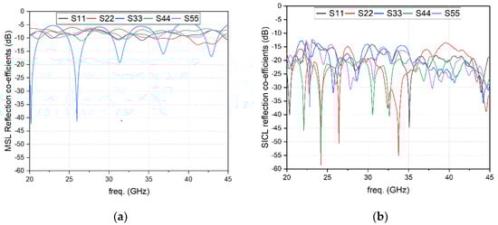
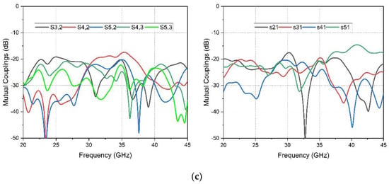
Figure 7.
Reflection coefficients of Rotman lens designed on (a) microstrip line and (b) SICL technology and (c) mutual couplings between the input beam ports of the SICL.
3. SICL-Based RL as Beamforming Network
As discussed in Section 2, the designed SICL-based RL steers the beams into the predefined steering angles at the desired frequencies. The S-parameters of the RL show the ability of the designed lens to give desired phase shifts to the beams from beam ports to the array ports. To form a beamforming network, radiating elements must be connected with the designed RL. Therefore, to examine the lens performance with an optimum antenna load, an antenna array of eight elements is developed and connected to the array ports of the SICL RL.
3.1. The 1 × 8 Antenna Array Design
For a patch antenna design, the resonant frequency (fr) of 26 GHz is chosen to be used for 5G applications. The substrate chosen is Rogers 4003C which is low-loss with high permittivity with a dielectric constant of 3.55 where the height (h) of the dielectric is 0.81 mm. The width of the patch antenna (W) can be calculated by the formulas []. The patch is fed along the y-axis yielding vertical polarization. The spacing between the antenna elements is critical as it controls the overall radiation pattern of the antenna array. For the maximum scan angle of θ, the spacing between the antenna elements d of the antenna array is chosen to fulfill the condition given in Equation (2) [].
The front and bottom views of the fabricated 1 × 8 antenna array with the soldered SMA connectors are shown in Figure 8a,b. The return loss of up to 27 dB for the antenna ports is achieved which proves good impedance matching of the designed antenna array as shown in Figure 8c.
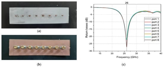
Figure 8.
(a) Front view and (b) bottom view of the fabricated 1 × 8 antenna array with connectors soldered and (c) the return losses at the respective ports of antenna array.
3.2. Integration of RL with Antenna Array
The RL design consisted of five beam ports and eight array ports. At the array ports, the 1 × 8 antenna array can be integrated as radiators for beamforming. For this purpose, the SnP touchstone file comprising the S-parameters of the designed RL is imported in the schematics of CST Studio Suite 2019 and integrated with the block of the 1 × 8 array of the patch antenna (designed in the previous section). Both results are combined using the AC combine function of the CST Studio schematic, and ports 1–5 are added accordingly.
4. Experimental Results and Discussion
The RL design is fabricated using cost-effective PCB techniques. Figure 9a shows the fabricated RL lens before adding the top layer, and Figure 9b shows the integration of the SICL RL along with the 1 × 8 antenna array connected with the cables. An in-house Anritsu ShockLine MS46122B vector network analyzer (VNA) is used for S-parameter measurements to measure both the amplitude and phase properties of the designed RL. Figure 9c shows the measurement setup of the designed prototype. The standard gain horn antenna shown in the inset is used to illuminate the SICL RL beamformer. The entire setup is placed into an anechoic chamber to eliminate the effects of reflections on the results []. The input beam ports are excited sequentially while terminating the remaining ports with the matched load of 50 Ω.
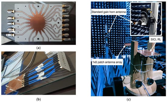
Figure 9.
(a) Fabricated SICL Rotman lens (upper conductor layer removed); (b) integration with 1 × 8 antenna array; (c) test fixture in Anechoic Chamber for radiation pattern measurements.
The measured insertion losses are given in Figure 10 when beam ports 1–3 are excited sequentially while the other ports are terminated to 50 Ω broadband matched loads. Low insertion losses of up to –9 dB are measured at the beam ports which shows good agreement with the simulated predictions. The 3D radiation patterns of the fully integrated SICL RL beamformer are illustrated in Figure 11 for the sequential excitement of the beam ports 1–5. A gain of up to 14.2 dBi is achieved at the resonant frequency of 26 GHz using the SICL RL, confirming its beamforming capabilities.
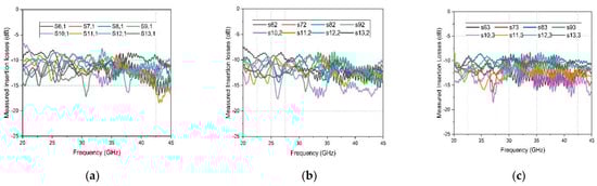
Figure 10.
Measured insertion losses of the fabricated SICL-based RL at array ports when (a) beam port 1 is excited, (b) beam port 2 is excited, and (c) beam port 3 is excited.
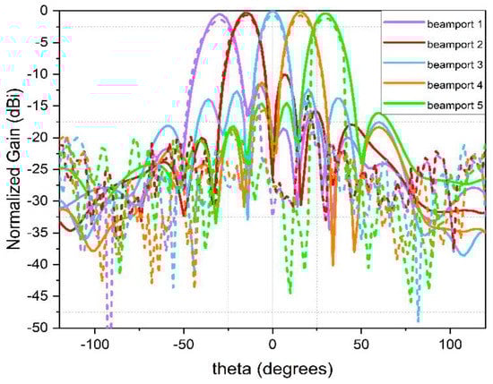
Figure 11.
Measured (represented in dotted lines) and simulated (represented in plain lines) gain plots when beam ports are excited sequentially.
The measured radiation patterns shown in Figure 11 show good agreement with the simulated results. The minor differences in the gain patterns can be associated with cable losses and dielectric losses which are measured separately up to 2.1 dB (not shown here). The beam is successfully steered to the pre-defined angles using the designed SICL RL beamformer. The beam steering angles are −30, −15, 0, +16 and +30 degrees when the input beam ports 1–5 are excited, respectively, as verified through the measurements.
The proposed SICL RL characteristics and performance parameters are compared with RLs fabricated with other fabrication technologies in the existing literature in Table 1. Due to low insertion losses of 10 dB for a wide frequency band of 20–45 dB, the proposed SICL RL beamformer provides an exceptionally high gain of up to 14.2 dBi.

Table 1.
Comparison with RLs developed with other technologies.
5. Conclusions and Future Directions
An efficient and low-loss RL-based beamforming network was designed and implemented for the first time using the SICL technology. First, an RL was developed having five input beam and eight output array ports using SICL technology. The SICL RL was then compared with the same design developed using conventional MSL technology. The results show low-insertion loss and good progressive phase-shifting behavior of the SICL-based RL. A 1 × 8 antenna array was then designed and connected with the RL structure to form a complete beamforming network. The beamformer was experimentally characterized in an anechoic chamber, and a high gain of up to 14.2 dBi was achieved with ±30 degrees of beam scanning capability. Direct applications of this technology include multi-target tracking radars, collision avoidance vehicles and multi-beam high-data-rate wireless communications. Future directions of this work include designing an extended two-stage 16 × 16 SICL-based 2D RL for azimuth and elevation scanning angles.
Author Contributions
M.S.A. and H.N. designed the Rotman lens beamformer, performed the simulations and wrote the initial draft of the manuscript. H.N. edited and modified the manuscript. M.A.B.A. and V.F.F. contributed to the concept. M.A.B.A. wrote the relevant Rotman lens text. N.S. performed the measurements and the validations. N.S., M.A.B.A. and V.F.F. supervised the whole research work. All authors have read and agreed to the published version of the manuscript.
Funding
This research received no external funding.
Institutional Review Board Statement
Not applicable.
Informed Consent Statement
Not applicable.
Data Availability Statement
The datasets generated during and/or analyzed during the current study are available from the corresponding author on reasonable request.
Conflicts of Interest
The authors declare no conflict of interest.
References
- Feldmann, A.; Gasser, O.; Lichtblau, F.; Pujol, E.; Poese, I.; Dietzel, C.; Wagner, D.; Wichtlhuber, M.; Tapiador, J.; Vallina-Rodriguez, N.; et al. The Lockdown Effect: Implications of the COVID-19 Pandemic on Internet Traffic. In Proceedings of the ACM Internet Measurement Conference (IMC ′20), New York, NY, USA, 2–4 November 2021. [Google Scholar]
- Li, Q.C.; Niu, H.T.; Papathanassiou, A.; Wu, G. 5G network capacity: Key elements and technologies. IEEE Veh. Technol. Mag. 2019, 9, 71–78. [Google Scholar] [CrossRef]
- Hemadeh, A.; Satyanarayana, K.; El-Hajjar, M.; Hanzo, L. Millimeter-wave communications: Physical channel models, design considerations, antenna constructions, and link-budget. IEEE Commun. Surv. Tutor. 2018, 20, 870–913. [Google Scholar] [CrossRef]
- 5G Spectrum. GSMA Public Policy Position, GSM Association. Available online: https://www.gsma.com/spectrum/wp-content/uploads/2022/06/5G-Spectrum-Positions.pdf; (accessed on 1 June 2021).
- Guidelines for Evaluation of Radio Interface Technologies for IMT-2020; Revision 1 to Document 5/57-E; ITU: Geneva, Switzerland, 2017.
- Tikhomirov, A.; Omelyanchuk, E.; Semenova, A. Recommended 5G frequency bands evaluation. In Proceedings of the Systems of Signals Generating and Processing, Moscow, Russia, 14–15 March 2018; pp. 1–5. [Google Scholar]
- Chen, W.C. 5G mmWAVE Technology Design Challenges and Development Trends. In Proceedings of the International Symposium on VLSI Design, Automation and Test (VLSI-DAT), Hsinchu, Taiwan, 10–13 August 2020. [Google Scholar]
- Lee, J.; Valentine, G. Multibeam array using Rotman lens and RF heterodyne. In Proceedings of the AP-S International Symposium on Antennas and Propagation Society, Baltimore, MD, USA, 20–26 October 1996. [Google Scholar]
- Ruze, J. Wide-Angle Metal-Plate Optics. Proc. IRE 1950, 38, 53–59. [Google Scholar] [CrossRef]
- Rotman, W.; Turner, R. Wide-angle microwave lens for line source application. IEEE Trans. Antennas Propag. 1963, 11, 623–632. [Google Scholar] [CrossRef]
- Smith, M.S. Design considerations for Ruze and Rotman lens. Radio Electron. Eng. 1982, 52, 181–187. [Google Scholar] [CrossRef]
- Smith, M.S. Amplitude performance of Ruze and Rotman lenses. Radio Electron. Eng. 1983, 53, 329–336. [Google Scholar] [CrossRef]
- Gagnon, D.R. Procedure for correct refocusing of the Rotman lens according to Snell’s law. IEEE Trans. Antennas Propag. 1989, 37, 390–392. [Google Scholar] [CrossRef]
- Archer, D.H.; Maybell, M.J. Rotman lens development at Raytheon ELectronic warfare systems. In Proceedings of the 2005 IEEE Antennas and Propagation Society International Symposium, Washington, DC, USA, 3–8 July 2005. [Google Scholar]
- Dong, J.; Zaghloul, A.I. Non-focal minimum phase-error planar Rotman lens. In Proceedings of the USNC/URSI National Radio Science Meeting, Boulder, CO, USA, 4 January 2008. [Google Scholar]
- Singhal, P.K.; Sharma, P.C.; Gupta, R.D. Rotman lens with equal height of array and feed contours. IEEE Trans. Antennas Propag. 2003, 51, 2048–2056. [Google Scholar]
- Pourahmadazar, J.; Denidni, T. Multi-beam tapered slot antenna array using substrate integrated waveguide Rotman lens. In Proceedings of the European Radar Conference (EuRAD), Paris, France, 9–11 September 2015. [Google Scholar]
- Remez, J.; Zeierman, E.; Zohar, R. Dual-polarized tapered slot-line antenna array fed by rotman lens air-filled ridge-port design. IEEE Antennas Wirel. Propag. Lett. 2009, 8, 47–851. [Google Scholar] [CrossRef]
- Abbasi, M.A.B.; Fusco, V.F.; Matthaiou, M. Millimeter Wave Hybrid Beamforming with Rotman Lens: Performance with Hardware Imperfections. In Proceedings of the 16th International Symposium on Wireless Communication Systems (ISWCS), Oulu, Finland, 27–30 August 2019. [Google Scholar]
- Christie, S. Rotman Lens-Based Retrodirective Array. IEEE Trans. Antennas Propag. 2012, 60, 1343–1351. [Google Scholar] [CrossRef]
- Gatti, F.; Bozzi, M.; Perregrini, L.; Wu, K.; Bosisio, R. A novel substrate integrated coaxial line (SICL) for wide–band applications. In Proceedings of the European Microwave Conference, Manchester UK, 10–15 September 2006. [Google Scholar]
- Cariou, M.; Potelon, B.; Quendo, C.; Cadiou, S.; Schlaffer, E.; Pessl, W.; Le Fevre, A. Compact X -Band Filter Based on Substrate Integrated Coaxial Line Stubs Using Advanced Multilayer PCB Technology. IEEE Trans. Microw. Theory Tech. 2016, 65, 496–503. [Google Scholar] [CrossRef]
- Li, X.; You, C.J.; Shao, Z.; He, Z. A wideband bandpass filter based on stepped impedance stubs and substrate integrated coaxial line. In Proceedings of the AsiaPacific Microwave Conference, Nanjing, China, 6–9 December 2015. [Google Scholar]
- Chen, Z.; Hong, W.; Chen, J. Low cost octave directional coupler based on substrate integrated coaxial line (SICL) technique. In Proceedings of the Asia Pacific Microwave Conference Proceedings, Kaohsiung, Taiwan, 4–7 December 2012. [Google Scholar]
- Junyu, S.; Qiang, L.; Yongle, W. High-directivity single- and dualband directional couplers based on substrate integrated coaxial line technology. In Proceedings of the 2013 IEEE MTT-S International Microwave Symposium Digest (MTT), Seattle, WA, USA, 2–7 June 2013. [Google Scholar]
- Cheng, L.; Fan, K.K.; Hao, Z.C.; Hong, W. Compact and wideband millimetre wave circularly polarised antenna array based on a SICL to waveguide transition. IET Microw. Antennas Propag 2017, 11, 2097–2103. [Google Scholar] [CrossRef]
- Bing, L.; Ke, X.; Lei, W. A novel slot array antenna with a substrateintegrated coaxial line technique. IEEE Antennas Wirel. Propag. Lett. 2017, 16, 1743–1746. [Google Scholar]
- Shao, Y.; Li, X.; Wu, L.; Mao, J. A wideband millimeter-wave substrate integrated coaxial line array for high-speed data transmission. IEEE Trans. Microw. Theory Tech. 2017, 65, 2789–2800. [Google Scholar] [CrossRef]
- Chu, P.; Hong, W.; Dai, L.; Tang, H.; Hao, Z.; Chen, J.; Wu, K. Wide stopband bandpass filter implemented with spur stepped impedance resonator and substrate integrated coaxial line technology. IEEE Microw. Wirel. Compon. Lett. 2014, 4, 218–220. [Google Scholar] [CrossRef]
- Miao, Z.; Hao, Z. A Wideband Reflectarray Antenna Using Substrate Integrated Coaxial True-Time Delay Lines for QLink-Pan Applications. IEEE Antennas Wirel. Propag. Lett. 2017, 16, 2582–2585. [Google Scholar] [CrossRef]
- Abbasi, M.A.B.; Tataria, H.; Fusco, V.F.; Matthaiou, M. On the Impact of Spillover Losses in 28 GHz Rotman Lens Arrays for 5G Applications. In Proceedings of the 2018 IEEE MTT-S International Microwave Workshop Series on 5G Hardware and System Technologies (IMWS-5G), Dublin, Ireland, 30–31 August 2018; pp. 1–3. [Google Scholar] [CrossRef]
- Musa, L.; Smith, M. Microstrip Port Design and Sidewall Absorption for Printed Rotman Lenses. IEEE Proc. 1989, 136, 53–58. [Google Scholar] [CrossRef]
- Ali, M.S.; Abbasi, M.A.B.; Shoaib, N. On the Phase-aligned Transmission Lines of a mmWave 5G Rotman lens Based Beamformer. In Proceedings of the 2021 1st International Conference on Microwave, Antennas & Circuits (ICMAC), Islamabad, Pakistan, 21–22 December 2021. [Google Scholar]
- Balanis, C.A. Antenna Theory: Analysis and Design; Wiley: Hoboken, NJ, USA, 2014. [Google Scholar]
- Shoaib, N. Vector Network Analyzer (VNA) Measurements and Uncertainty Assessment; Springer International Publishing AG: Cham, Switzerland, 2017. [Google Scholar]
- Cheng, Y.J.; Hong, W.; Wu, K.; Kuai, Z.Q.; Yu, C.; Chen, J.X.; Zhou, J.Y.; Tang, H.J. Substrate Integrated Waveguide (SIW) Rotman Lens and Its Ka-Band Multibeam Array Antenna Applications. IEEE Trans. Antennas Propag. 2008, 56, 2504–2513. [Google Scholar] [CrossRef]
- Jastram, N.; Filipovic, D.S. Design of a wideband millimeter wave micromachined Rotman lens. IEEE Trans. Antennas Propag. 2015, 63, 2790–2796. [Google Scholar] [CrossRef]
- Wu, W.-J.; Zhang, Z.-Y.; Zhao, Y.-R.; Liu, Q.-F.; Wang, C.; Zuo, Y. Design of Multi-Beam Antenna Based on Rotman Lens. In Proceedings of the 2019 International Applied Computational Electromagnetics Society Symposium—China (ACES), Nanjing, China, 8–11 August 2019; pp. 1–2. [Google Scholar] [CrossRef]
Disclaimer/Publisher’s Note: The statements, opinions and data contained in all publications are solely those of the individual author(s) and contributor(s) and not of MDPI and/or the editor(s). MDPI and/or the editor(s) disclaim responsibility for any injury to people or property resulting from any ideas, methods, instructions or products referred to in the content. |
© 2022 by the authors. Licensee MDPI, Basel, Switzerland. This article is an open access article distributed under the terms and conditions of the Creative Commons Attribution (CC BY) license (https://creativecommons.org/licenses/by/4.0/).