Abstract
The traditional method of taxiing for civil aircraft, which relies on their engines, may be surpassed by the new method of towing taxi-out due to its superior advantages such as reduced energy consumption, lower emissions, and higher efficiency. However, the towing taxi-out system poses a challenge to lateral stability due to the concentration of mass at the rear, leading to severe instability when turning at high speeds. To address this issue, a nonlinear civil aircraft towing and taxiing system model and a linear four-degree-of-freedom civil aircraft towing and taxiing system reference model were established using TruckSim and Matlab/Simulink software. The fuzzy proportional–integral–derivative controller was utilized, with the braking torque of each wheel serving as the control variable and the real-time yaw rate difference and its rate of change as the fuzzy control input. The controller was compared and validated with a traditional PID controller. The results of the simulation showed that the fuzzy PID control has better nonlinear characteristics and stronger adaptability to operating conditions compared to traditional PID control, providing timely, effective, adaptive, and robust control effects for the vehicle dynamics model. Under the fuzzy PID control, the peak yaw speed of the civil aircraft decreased to 10 degrees per second under double-shift conditions, representing an increase of 23.1%. Furthermore, the lateral stability and safety of the towing taxi-out system were improved, as evidenced by the reduction in the yaw rate of the tractor and civil aircraft under the hook condition. The use of this controller provides valuable technical guidance and support for the practical development and safe application of the towed glide mode.
1. Introduction
During traditional flight departure, the civil aircraft starts its engine after being pulled out of the berth by a tractor and taxis to the runway under its own power. However, this process results in significant fuel consumption, waste discharge, and high risk of foreign object ingestion, as the engines run at inefficient and idle speeds. Moreover, the cooperative effort required across multiple departments results in low departure efficiency, which fails to meet the high standards for quality and healthy development of civil aviation worldwide. As illustrated in Figure 1 [1], a new type of traction departure mode, operated by civil organizations, has emerged as a research hotspot. This mode involves shutting down the civil aircraft engine during departure and relying on the power of the tractor to complete the departure behavior. The traction taxiing system, composed of the civil aircraft and tractor, greatly reduces noise pollution and greenhouse gas emissions by utilizing only the tractor’s power during departure. However, the civil aircraft traction taxiing system is prone to transverse instability phenomena such as wobbling, sideslipping, and jack-knifing (when the longitudinal angle between the tractor and civil aircraft exceeds 90 degrees), which can result in major traffic safety accidents due to the high speed and heavy load. Therefore, research on the mechanism of transverse instability and active control of the civil aircraft traction system is necessary to enhance driving safety and promote the effective application of the traction departure mode.
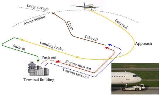
Figure 1.
Schematic diagram of civil aircraft departure and taxiing process.
Currently, the predominant research in this field concentrates on the kinematic and dynamic modeling of the traditional push-out stage system, and only a few nonlinear terms are considered in the modeling process. For instance, Zhou created a nonlinear dynamic model for aircraft traction systems on ships [2,3]. The model was used to investigate the stability of the system during straight running and turning. Meanwhile, Wang et al. formulated a dynamic model for the traction system of Boeing 737–800 aircraft that considers the nonlinearity of the tractor-trailer air suspension. They compared and analyzed the air spring suspension and leaf spring suspension based on their impact on the ride comfort of the system, and concluded that the air suspension meets the requirements of traction ride comfort [4,5,6].
Furthermore, the “fifth wheel”, which serves as the primary connecting component of the tractor-semi-trailer system, exhibits similarities to the load-bearing, longitudinal three-point clamping connection mechanism employed in aircraft traction systems. Additionally, this system’s structural characteristics concentrate its mass towards the rear. Therefore, the current dynamic modeling methods and instability mechanism analysis means used for the tractor-semi-trailer system can serve as a reference for this study.
Brown et al. established a linear 5-degree-of-freedom yaw model for the semi-trailer train and validated it with a nonlinear model developed using Trucksim [7]. Kim aimed to improve the maneuverability and stability of articulated vehicles by establishing a three-degree-of-freedom linear model for a trailer-steered automotive train and identifying key parameters for specific speeds and steering wheel angles using simulated annealing particle swarm optimization [8]. Lei and others used a joint vehicle model based on the kinematics of tractors and trailers, and applied linear and nonlinear methods to analyze the stability of the model. Simulation and experimental validation showed the stability analysis results for the joint vehicle and explored the influence of different parameters on vehicle stability [9].
Currently, due to the short system pushing distance in the traditional sliding mode, its driving safety issues have not attracted widespread attention, and active stabilization control methods have not yet been effectively applied. However, the differential braking instability state vehicle stabilization control technology proposed in this project has been widely applied in many fields. Bai and others introduced a method to improve the lateral stability of semi-trailers using the vehicle’s braking system, controlling the braking torque to introduce additional yaw torque and thereby increasing the lateral stability of the semi-trailer. Simulation and experimental validation showed that the method effectively improved the lateral stability and handling performance of the semi-trailer, reducing accident risk [10]. Xu proposed an active control method for trailer wheel active steering, planning the target path of the trailer through displacement registers, and adjusting the trailer wheel steering angle in real time based on the look ahead deviation of the actual path to reduce the deviation of the trailer’s driving path. Simulation results showed that the method could reduce the lateral force on the articulation point and tires, contributing to improved vehicle stability [11]. Yang established a 14-degree-of-freedom nonlinear model of a semi-trailer train as the control object, and designed a PI controller with the yaw response deviation between the linear 4-degree-of-freedom single-track semi-trailer train model and the nonlinear model as the control variable. Independent yaw stability torque for the tractor and trailer was generated and controlled using a differential braking strategy with single-wheel braking, validating the improvement of the yaw stability of the semi-trailer train under single-shift line simulation operation [12,13,14]. Jin and others proposed using the position of the zero-torque point as a reference index in the rollover warning system in 2017 and controlling the stability of commercial vehicles through differential braking, comparing fuzzy control, traditional PID control, and fuzzy PID control in the test. The experimental results showed that the fuzzy PID control had the best control performance in differential braking [15,16,17]. Li Nan addressed the issue of dangerous phenomena such as jack-knifing during cornering braking of semi-trailer trains by judging the stability of semi-trailer trains during cornering based on the difference between the actual yaw rate and the desired yaw rate. A differential braking controller was designed using fuzzy PID control, and the control strategy was tested in a simulation experiment based on the Trucksim/Simulink joint simulation platform [18,19]. Xu Xing and others studied the towed recreational vehicle, taking the vehicle’s articulation angle and yaw rate as control targets, and adopting a multi-objective PID weighted and coordinated control [20,21].
In summary, the research on the dynamics of civil aircraft towed taxiing systems is still in its infancy, with most studies focusing on low-speed operations and traditional departure modes. There is a need for further exploration and research on the system’s dynamics at high speeds and under new departure modes. The lateral active stabilization control of civil aircraft towed taxiing systems is still in the early stages of exploration, and there is much room for improvement. To address these gaps, this paper uses a multi-body dynamic model and Trucksim-Simulink co-simulation to study and analyze the dynamics of the traction system under various working conditions. The results of this study can provide theoretical support and reference for the safe landing application of the new traction departure mode.
2. Establishment of Dynamic Model of Civil Aircraft Towing Taxi-Out System
2.1. The Trucksim Model
The 2A tractor accompanied by a 1A van trailer, incorporated within Trucksim, has been chosen to correspond with a 4 × 2 tractor and a single-axle van trailer, with the intention of mimicking the genuine civil aircraft traction and taxi system, and exhibiting the authentic operational circumstances. The “fifth wheel” structure of the system corresponds to the wheel clamping mechanism. The model characteristics of the tractor and civil aircraft employed are visibly presented in Table 1 and Table 2. Subsequently, the braking torque of every wheel, estimated by means of the Simulink simulation, is imparted to the Trucksim model, allowing for differential braking via co-simulation.

Table 1.
Model parameters of Weihai Guangtai AM210 rodless aircraft tractor.
Table 2.
Model parameters of the Boeing 737–800 aircraft.
Vehicle configuration and comparison of the fifth wheel and clamping mechanism are shown in Figure 2.
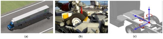
Figure 2.
Vehicle configuration and comparison of the fifth wheel: (a) Trucksim vehicle configuration; (b) traction vehicle clamping mechanism; (c) Trucksim fifth wheel setup.
2.2. The Mathematical Model
The towing taxi-out system of a civil aircraft is a complex multi-degree-of-freedom spatial motion system consisting of two independent and inter-related parts. The motion of the tractor and the civil aircraft is interdependent due to the coupling of the wheel holding mechanism on the tractor. Compared to a single car or a train of cars, the lateral stability of the tractor taxiing system of a civil aircraft is more complex.
Assuming that the positions of the traction point and the centroid point lie on the longitudinal axis of the tractor, a four-degree-of-freedom monorail two-centroid mathematical model is simplified based on the following assumptions, taking into account transverse force and movement. This model is referred to as the monorail civil aircraft’s towing taxi-out model.
- (1)
- The steering wheel angle has a linear relationship with the front wheel angle, with the latter being the direct input.
- (2)
- The longitudinal speed is maintained at a constant value.
- (3)
- The function of tractor suspension is ignored, and the vertical, pitch, and roll motion is disregarded.
- (4)
- The effect of aerodynamic action and changes in pavement adhesion condition is not considered.
- (5)
- The tire’s sidewise characteristics are assumed to be in a linear range.
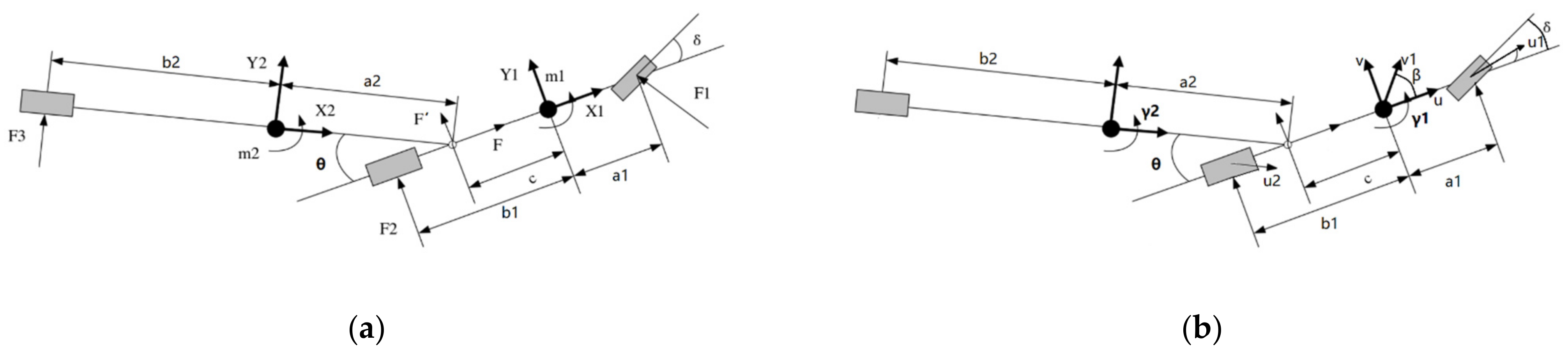
Figure 3 shows the yaw motion diagram of civil aircraft’s towing taxi-out system.
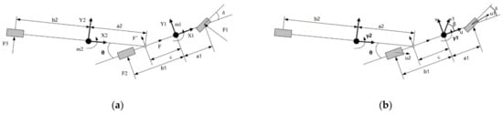
Figure 3.
The yaw motion diagram of civil aircraft’s towing taxi-out system: (a) lateral force analysis; (b) lateral dynamics analysis.
The model for the towing taxi-out system of the monorail civil aircraft, which is simplified in nature, encompasses four degrees of freedom, namely the lateral and yaw motion of the tractor and civil aircraft. As per the principles of Newtonian mechanics, the differential equations for the lateral and yaw motion of both the tractor and civil aircraft have been listed correspondingly.
Equations of tractor as follows:
Equations of civil aircraft as follows:
Based on the linear monorail model properties and the transverse movement constraint that exists between the tractor and civil aircraft at the traction point joint, it can be inferred that:
In a geodetic coordinate system XOY, a1 and b1 represent the distances between the tractor’s center of mass and its front and rear axles, respectively. Similarly, a2 and b2 represent the distances from the civil aircraft’s center of mass to its front and main landing gear, respectively. vx denotes the longitudinal velocity while vy1 and vy2 represent the lateral speeds of the tractor and civil aircraft, respectively. γ1 and γ2 denote the yaw rates of the tractor and civil aircraft, respectively. ay1 and ay2 represent the front and rear lateral acceleration of the tractor, respectively, while ay3 represents the lateral acceleration of the civil aircraft’s main wheel. K1 and K2 denote the lateral stiffness of the tractor’s front and rear wheels, respectively, while K3 represents that of the civil aircraft’s main wheel. α1, α2, α3 denote side angles for front/rear wheels of tractor/main wheel of civil aircraft, respectively, while β1/β2 denote side slip angles for centroid of tractor/civil aircraft, respectively. F1/F2/F3 denote lateral forces for front/rear wheels of tractor/main wheels of civil aircraft.
This simplifies to the following equations:
After organizing the above formula and converting it into matrix form PtXt′ + QtXt = PtUt, we can express it in state-space form:
The matrix in the above equation is:
2.3. Model Verification
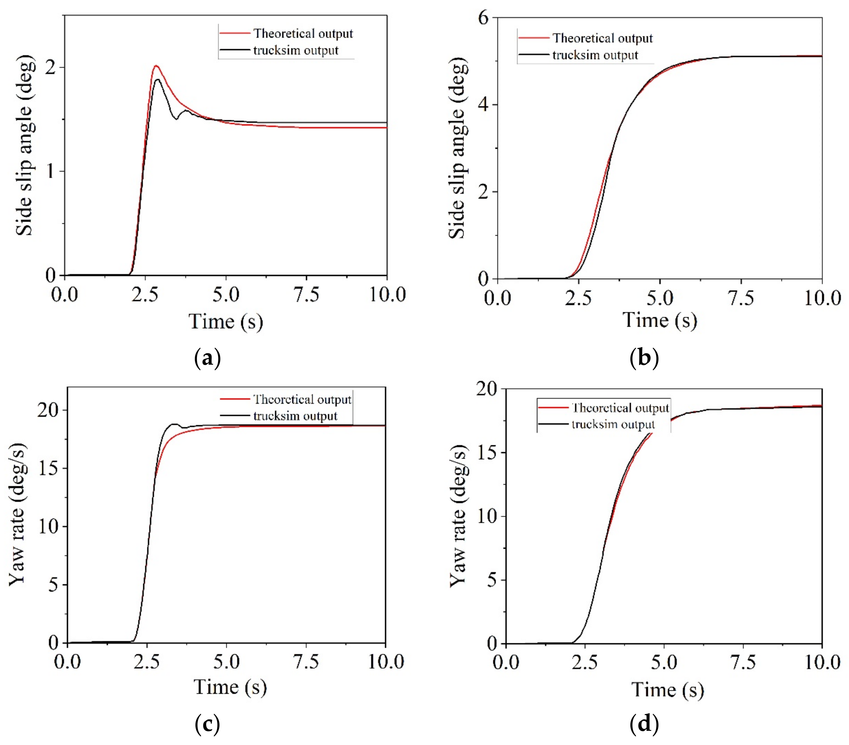
When the velocity reaches 40 km per hour and the steering wheel is rotated 180 degrees, the aforementioned data can be incorporated into a four-degree-of-freedom theoretical model for civil aircraft towing taxi-out. The resulting calculations can then be juxtaposed with those derived from Trucksim real vehicles as depicted in Figure 4.
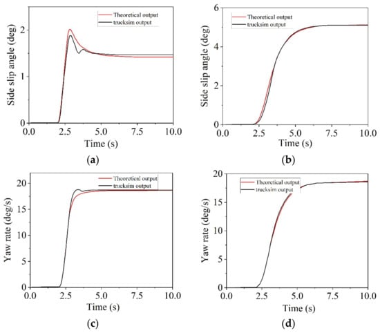
Figure 4.
Comparison diagram of theoretical model and Trucksim simulation: (a) tractor side slip angle; (b) civil aircraft side slip angle; (c) tractor yaw rate; (d) civil aircraft yaw rate.
3. Civil Aircraft Towing Taxi-Out System Stability Control Strategy
There are several active control strategies for stability control in civil aircraft towing taxi-out systems. These can be categorized into active steering, active suspension, differential braking and traction control. Among these strategies, differential braking improves yaw stability by applying different braking forces to the left and right wheels to produce an additional yaw moment.
In this paper, the stability control component of the integrated control algorithm is based on a differential braking control strategy.
Traditional control methods are based on the precise model of the controlled object, resulting in poor flexibility and suitability for solving relatively simple linear and time-invariant control problems. In practical applications, traditional control methods face many challenges, including uncertainty, complexity, time variation, and the lack of precise mathematical models in real systems. Intelligent control involves designing a controller or system with learning, abstraction, reasoning, and decision-making capabilities, capable of responding to environmental information changes, and replacing human tasks to effectively control complex systems.
Based on the analysis above, considering the real-time and complexity characteristics of civil aircraft traction taxi-out systems, this paper employs a fuzzy PID control for the upper-level controller. In situations such as turning and braking or high-speed driving, the vehicle’s structural parameters, front-wheel steering angle, speed, and road adhesion coefficient greatly impact the system, making it a nonlinear problem. Conventional PID control has poor adaptability to operating conditions; fuzzy control algorithms, due to the lack of an integral mechanism, are essentially nonlinear P or PD control algorithms, resulting in a steady-state error, which adversely affects the system’s control accuracy and is unfavorable for vehicle control. Fuzzy PID control, on the other hand, can incorporate human control experience and methods in a standardized manner and automatically adjust the kp, ki, and kd parameters, satisfying nonlinear system control requirements, thereby enabling the vehicle dynamics model to achieve timely, effective, adaptive, and robust control effects.
At the same time, this paper compares traditional PID control with fuzzy PID control to demonstrate the nonlinearity and effectiveness of the fuzzy PID control. By comparing these two methods, the goal is to validate the improved performance of the fuzzy PID control in addressing the complex and nonlinear nature of the civil aircraft towing taxi-out system, ultimately enhancing stability and overall control.
3.1. Control System Architecture
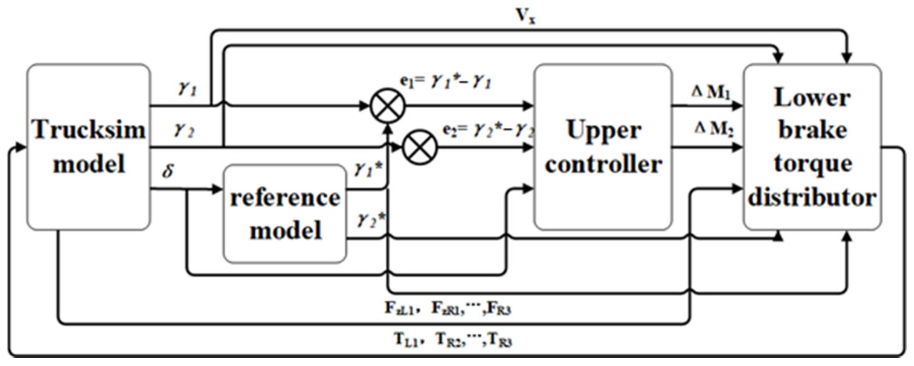
Firstly, the front wheel angle replaces the steering wheel angle as the system input. The yaw rate output by Trucksim represents the actual value while that output by the four-degree-of-freedom theoretical model represents the theoretical value. The difference between these values determines whether there is a risk of instability in the civil aircraft towing taxi-out system. If such a risk exists, stability control is initiated.
The difference between the theoretical and actual yaw rates of both tractor and aircraft (e1 and e2) is derived along with their rates of change (ec1 and ec2). These values serve as inputs to the upper controller which outputs additional pendulum torque for both tractor and aircraft (ΔM1 and ΔM2). These values serve as inputs to the lower controller which calculates braking torque for each wheel based on a brake torque distribution algorithm.
Parameters obtained from Trucksim include front wheel angle, driving speed, yaw speed, wheel speed and vertical load while those input to Trucksim from Simulink include braking torque for six wheels. The structure of this control system is shown in Figure 5.
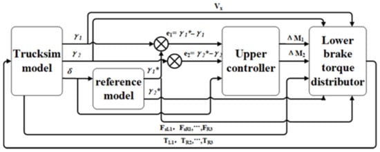
Figure 5.
Structure of lateral stability control system for aircraft towing and taxiing system.
3.2. The Design of the Upper Controller
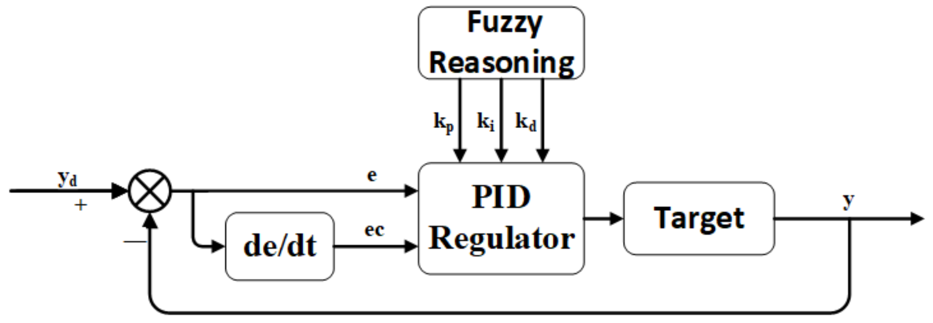
The upper controller employs fuzzy PID control. In the tractor fuzzy PID controller, the difference between theoretical and actual yaw rates (e1) and its rate of change (ec1) serve as inputs to output additional yaw torque for the tractor (ΔM1). Similarly, in the civil aircraft fuzzy PID controller, the difference between theoretical and actual yaw rates (e2) and its rate of change (ec2) serve as inputs to output additional yaw moment for the aircraft (ΔM2). The associated structure is shown in Figure 6.
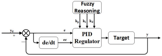
Figure 6.
Fuzzy PID control structure.
The fuzzy controller converts input variables into fuzzy signals for identification rather than reading them directly. These fuzzy signals can be divided into seven levels: negative large (NB), negative medium (NM), negative small (NS), zero (ZO), positive small (PS), positive medium (PM) and positive large (PB).
The knowledge base consists of a database and a rule base. The database provides data required by the inference machine such as input variables and membership functions while the rule base mimics human reasoning and is based on long-term experimental experience. The inference machine performs fuzzy reasoning.
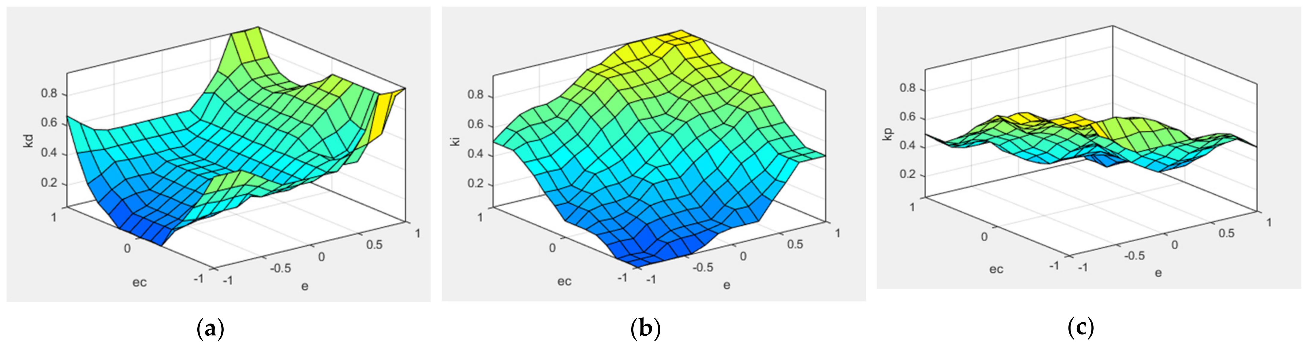
In a PID system, input variables are directly controlled to obtain an optimal control system. Based on simulation experience in different working conditions, the theoretical domain values for inputs e and ec of both tractor and aircraft fuzzy controllers are [−1, 1] while those for outputs kp, ki and kd are all [0, 1]. NB and PB follow a Gaussian distribution while other parts follow a triangular function. With two input fuzzy signals each having 7 levels, a total of 49 fuzzy rules must be written.
The surface relationship between input and output parameters of the fuzzy PID is shown in Figure 7.

Figure 7.
The relation between input and output surface: (a) the relation between input and output surface of kp; (b) the relation between input and output surface of ki; (c) the relation between input and output surface of kd.
A Simulink model for the fuzzy PID controller is constructed utilizing the output parameters kp, ki and kd as the respective parameters for the proportional, integral and derivative components of the PID controller.
3.3. The Design of the Lower Controller
To simplify calculations, the following conventions are established in this paper: the left direction is designated as positive while the right direction is designated as negative. If the yaw rate exceeds zero, the vehicle is turning left; if it falls below zero, the vehicle is deemed to be turning right. The discrepancy between the actual and theoretical yaw rates can then be used to determine whether the vehicle is understeering or oversteering. The additional yaw moment determined by the aforementioned fuzzy PID controller is achieved through differential braking force applied to individual wheels. When the tractor turns left and oversteers, differential braking force is applied to the right wheel. The relationship between additional yaw moment and braking force can be expressed as follows:
where ΔM1 represents the additional yaw moment of the tractor, Fxr1 and Fxr2 denote the longitudinal braking force applied to the front axle and right wheel of the rear axle of the tractor, respectively, and l1 and l2 represent the wheelbase of the front and rear axles of the tractor, respectively. When the steering angle of the tractor is minimal, this equation can be reformulated as follows:
Assuming that the tire does not lock and its braking force is roughly proportional to the tire’s vertical load, the distribution of braking force can be computed using the following equation:
where Fzr1 and Fzr2 denote the vertical forces acting on the front and rear axles of the tractor, respectively. r1 and r2 represent the effective braking radius of each wheel, and the formula for calculating the braking torque Tr1 and Tr2 for each wheel is as follows:
The additional yaw moment for civil aircraft can only be supplied by a single wheel on one side. As such, its additional yaw moment can be directly computed using the following equation:
where Tr3 represents the braking torque applied to the right main wheel of a civil aircraft, l3 denotes the wheelbase of the main wheel of a civil aircraft, and r3 represents the effective rolling radius of the main wheel of a civil aircraft. The process for calculating brake force distribution under other instability conditions is identical to that described above for left-turn oversteering. The distribution rules for target brake wheels under different yaw instability conditions are presented in Table 3.
Table 3.
Target brake wheel allocation rules.
4. Simulation Results
In order to validate the efficacy of the controller designed in this paper, the nonlinear civil aircraft towing taxi-out system model established in Trucksim is exported as an S-function to Matlab/Simulink (Available online: https://www.mathworks.com/products/simulink.html, accessed on 20 March 2023) to construct a co-simulation model. In this model, controller A represents the traditional PID controller, while controller B represents the fuzzy PID controller.
4.1. The Double-Lane Change Test
The adhesion coefficient is set to 0.8, the initial vehicle speed to 70 km/h, the simulation time to 15 s and the simulation step to 0.001 s. The input curve for steering wheel angle is depicted in Figure 8a, while the path diagram is shown in Figure 8b. The results of the simulation are presented in Figure 9.
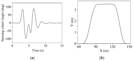
Figure 8.
Input setting: (a) steering wheel angle; (b) route setting.
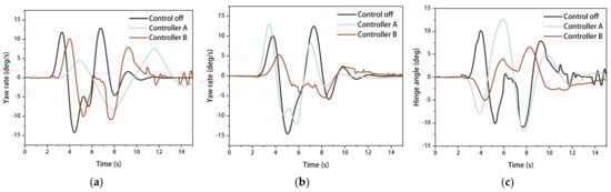
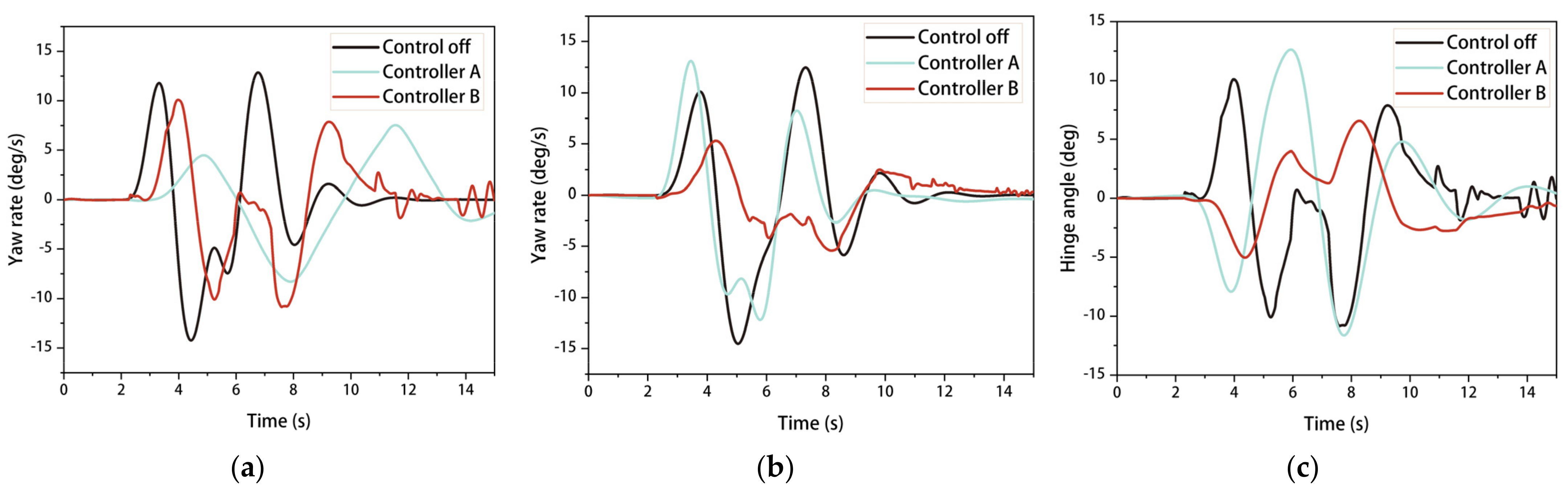
Figure 9.
Simulation results of the double-lane change test: (a) comparison of tractor yaw rate; (b) comparison of civil aircraft yaw rate; (c) comparison of hinge angle.
Figure 9 illustrates that when the control is turned off, the maximum yaw rate of the civil aircraft reaches 13 degrees per second. After controller A is activated, the peak value is reduced to 10 degrees per second, representing an improvement of 23.1%. When controller B is activated, the peak yaw rate of the tractor is also reduced compared to controller A, and the peak articulation angle decreases to approximately 6 degrees, eventually approaching 0. This effectively suppresses the sideslip phenomenon of the civil aircraft.
4.2. Steering Wheel Angle Step Input
The adhesion coefficient is set to 0.8, the initial vehicle speed to 70 km/h, the start time for steering wheel angle step to 1 s, the maximum steering wheel angle to 180 degrees, the simulation time to 8 s and the simulation step to 0.001 s. The results of the simulation are presented in Figure 10.
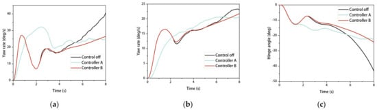
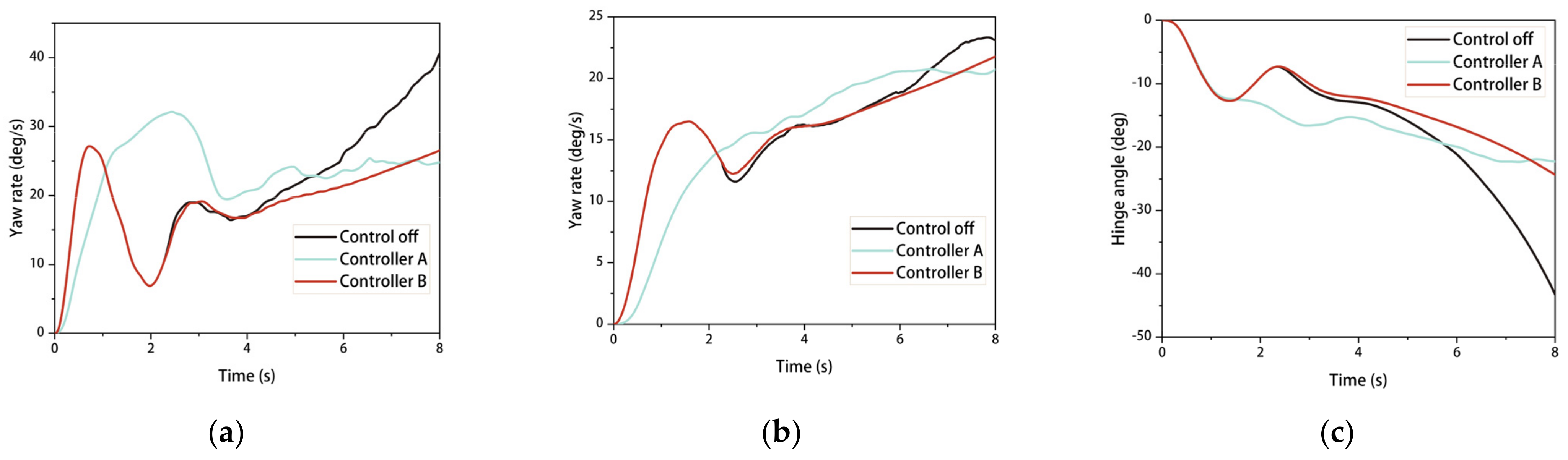
Figure 10.
Simulation results of steering wheel angle step input: (a) comparison of tractor yaw rate; (b) comparison of civil aircraft yaw rate; (c) comparison of hinge angle.
Figure 10 illustrates that when the control is turned off, at 10 s, the tractor’s yaw rate is 40 degrees per second, the civil aircraft’s yaw rate is 24 degrees per second, and the articulation angle is −43 degrees. After controllers A and B are activated, these values are reduced to 24 degrees per second, 20 degrees per second, and around −23 degrees, respectively, representing improvements of 60%, 16.7%, and 46.5%. This effectively suppresses the jack-knifing phenomenon of the civil aircraft.
4.3. The Steady Static Circular Test
The adhesion coefficient is set to 0.8, the initial vehicle speed to 70 km/h, the path to a circular track with a radius of 30 m, the simulation time to 50 s and the simulation step length to 0.001 s. The results of the simulation are presented in Figure 11.
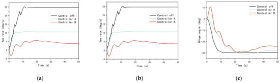
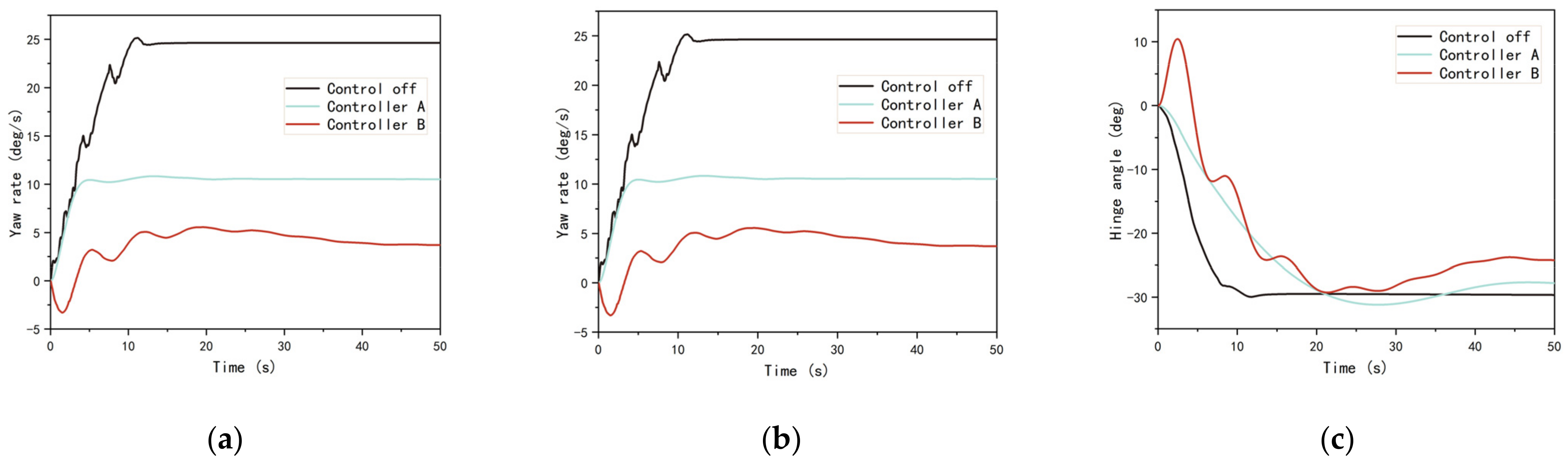
Figure 11.
Simulation results of the double-lane change test: (a) comparison of tractor yaw rate; (b) comparison of civil aircraft yaw rate; (c) comparison of hinge angle.
As shown in Figure 11, when the control is turned off, the tractor’s yaw rate reaches a peak of 25 degrees per second at 12 s. With controller A activated, the yaw rate is reduced to 10 degrees per second, and with controller B activated, it is reduced to 3 degrees per second, representing improvements of 66% and 88%, respectively. When the control is turned off, the civil aircraft’s yaw rate reaches a peak of 26 degrees per second at 11 s, and stabilizes at 25 degrees per second 1 s later. With controller A activated, the yaw rate is reduced to 10 degrees per second, and stabilizes at 10 degrees per second after 5 s, representing a 60% improvement. With controller B activated, the yaw rate stabilizes at 2.4 degrees per second after 20 s, representing a 90.4% improvement. The rate of change in the articulation angle is significantly reduced, and the smoothness of the civil aircraft towing taxi-out system is markedly improved.
4.4. The Hook
Configure the coefficient of adhesion to 0.8, set the initial velocity of the vehicle to 70 km/h, establish a simulation duration of 15 s and a simulation interval of 0.001 s. Refer to Equation (31) for the input curve of the steering wheel angle and observe the simulation outcome in Figure 12.
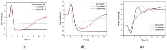
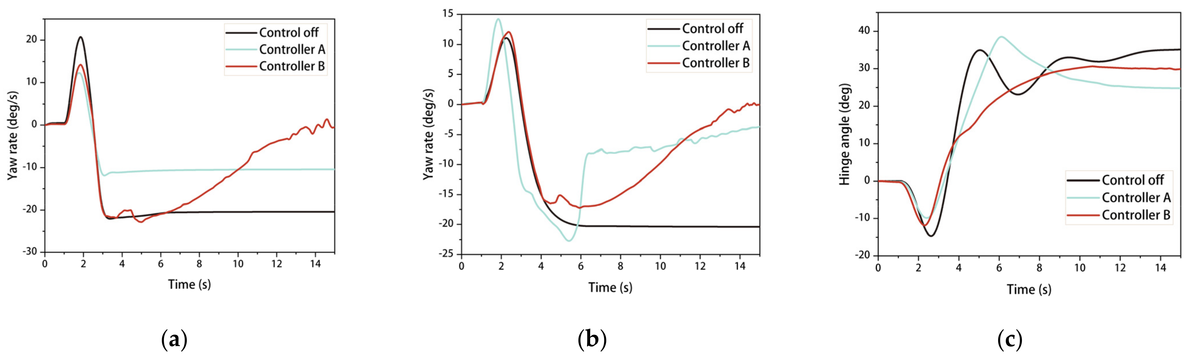
Figure 12.
Simulation results of the hook: (a) comparison of tractor yaw rate; (b) comparison of civil aircraft yaw rate; (c) comparison of hinge angle.
Figure 12 illustrates that when the control is turned off, the yaw rates of the tractor and civil aircraft sharply increase after approximately 2 s. With controller A and controller B activated, the yaw rates of the tractor and civil aircraft begin to decrease after 5 s and eventually reduce to around 0 degrees per second. The change in the articulation angle is also smoother with controller B activated, enabling the towing taxi-out system to travel stably.
5. Conclusions
The towed taxi departure method for civil aircraft has emerged as a favored mode of departure for future civil aircraft. To enhance the lateral stability of the system, Trucksim and Matlab/Simulink software were employed to construct a nonlinear model of the civil aircraft towed taxiing system and a linear reference model with four degrees of freedom. A fuzzy PID control algorithm was chosen as the upper controller, with fuzzy rules and discussion domains designed accordingly and compared with traditional PID control. The yaw rate deviation and its rate of change were used to determine the additional yaw torque required by tractors and civil aircraft. The lower controller distributed the additional yaw moment to the corresponding wheel and calculated the wheel braking moment, achieving active stabilization of the traction taxi system through differential braking technology.
Co-simulation results using Trucksim-Matlab/Simulink demonstrated that with controllers A and B activated, both improved the lateral stability of the civil aircraft towing taxi-out system. However, due to the inherent real-time and complex characteristics of the system, and the significant impact of vehicle structural parameters, front wheel steering angle, vehicle speed, and road adhesion coefficient on it during turning braking or high-speed driving, the system is a nonlinear problem. Traditional PID control has poor adaptability to operating conditions, while fuzzy PID control can incorporate human control experience and methods in a standardized manner, and automatically adjust the kp, ki, and kd parameters, meeting the requirements for controlling nonlinear systems, and thus enabling timely, effective, adaptive, and robust control of the vehicle dynamics model.
Ultimately, with controller B activated under double-layer differential braking control, the peak yaw speed of civil aircraft decreased to 10 degrees per second and stability increased by 23.1%. With steering wheel angle step input, the hinged angle decreased to −23 degrees at 10 s, an increase of 46.5%. Under steady-state stabilization conditions, the yaw rate of both tractor and civil aircraft remained stable below 3 degrees, increasing by 88% and 90.4%, respectively. With hook engagement, the yaw rate of both tractor and civil aircraft was reduced from −20 degrees per second to approximately 0 degrees per second, effectively stabilizing the traction taxi system and improving its operational stability. The double-layer differential braking control strategy proposed in this paper can provide theoretical and methodological support for the safe implementation of the towing taxi-out departure mode.
Author Contributions
Conceptualization, J.Q. and W.Z.; methodology, J.Q.; software, H.W.; validation, J.Q., Q.L. and W.Z.; formal analysis, H.W.; investigation, J.S.; resources, W.Z.; data curation, H.W.; writing—original draft preparation, J.Q. and H.W.; writing—review and editing, J.Q. and W.Z.; visualization, H.W. and J.S.; supervision, W.Z.; project administration, J.Q.; funding acquisition, J.Q. and W.Z. All authors have read and agreed to the published version of the manuscript.
Funding
This research was funded by Fundamental Research Funds for The Central Universities, grant number 3122021050 and Key support project of the Civil Aviation Joint Fund of the National Natural Science Foundation of China, grant number U2033208.
Data Availability Statement
The data are not publicly available due to privacy concerns.
Conflicts of Interest
The authors declare no conflict of interest.
References
- Qin, J.H.; Liu, J.W.; Lin, Q.W.; Zhang, W. Research on Instability and “Jack-Knifing” of Civil Aircraft Towing Taxi-Out System. Appl. Sci. 2023, 13, 3636. [Google Scholar] [CrossRef]
- Zhou, L.J. Stability Study of the Tractor-Aircraft System on Board a Ship. Ph.D. Thesis, Harbin Engineering University, Harbin, China, 2012. [Google Scholar]
- Zhou, L.J.; Wang, N.J.; Zhang, D.F. Adaptive and variable structure control with sliding mode for tractor-aircraft system. Control. Theory Appl. 2012, 29, 529–534. [Google Scholar]
- Zhu, H.; Wang, L.W.; Luo, X.Y. Simulation analysis of air-suspension rodless aircraft tractor dynamics. Mach. Tools Hydraul. 2018, 46, 144–147. [Google Scholar]
- Wang, L.W.; Liu, B.; Sun, Y.K.; Zhang, W. Landing gear load simulation of towbarless traction system on uneven road. J. Civ. Aviat. Univ. China 2019, 37, 33–37, 43. [Google Scholar]
- Wang, L.W.; Wu, Z.H.; Zhang, W. Kinematics Analysis for Clamping and Lifting Mechanism of Tow-bar-less Aircraft Tractor. Mach. Tool Hydraul. 2015, 43, 15, 54–57. [Google Scholar]
- Brown, J.; He, Y.; Lang, H. Modeling and Control Design for Active Trailer Steering of Heavy Vehicles. In Proceedings of the ASME 2017 International Mechanical Engineering Congress and Exposition; American Society of Mechanical Engineers: New York, NY, USA, 2017; p. V012T16A017. [Google Scholar]
- Kim, K.; Guan, H.; Wang, B. Active steering control strategy for articulated vehicles. Front. Inf. Technol. Electron. Eng. 2016, 17, 576–586. [Google Scholar] [CrossRef]
- Lei, T.; Wang, J.; Yao, Z. Modelling and stability analysis of articulated vehicles. Appl. Sci. 2021, 11, 3663. [Google Scholar] [CrossRef]
- Bai, Z.; Lu, Y.; Li, Y. Method of improving lateral stability by using additional yaw moment of semi-trailer. Energies 2020, 13, 6317. [Google Scholar] [CrossRef]
- Xu, X.M.; Zhang, L.; Liu, K.; Chen, N. Research on Active Steering Control of Trailer Wheels for a Tractor-Semitrailer. Automob. Technol. 2018, 11, 36–40. [Google Scholar]
- Yang, X.J.; Yang, C.X.; Zhang, X.; Qu, R. Yaw Stability Control for Tractor-Semitrailer Combination Based on Active Braking. Automot. Eng. 2011, 33, 955–961. [Google Scholar]
- Yang, X.J.; Kang, N.; Liu, M.X.; Zhou, P.; Rong, J.X. Yaw Stability Control for Tractor-semitrailer Combination Based on optimal control allocation Method. China J. Highw. Transp. 2013, 26, 182–190. [Google Scholar]
- Li, H.Q.; Yang, X.J.; Chen, S.Q.; Gao, J. Stability Control of tractor—Semitrailer Vehicle Based on Parameter Estimation. Comput. Digit. Eng. 2014, 42, 1311–1315, 1479. [Google Scholar]
- Jin, L.Q.; Shi, G.N.; Yu, Y.J.; Wang, B.W. Anti-Roll Control for Commercial Vehicles Based on Zero-Moment Point Position and Fuzzy Control. Automot. Eng. 2017, 39, 1062–1067. [Google Scholar]
- Liu, G.; Xu, W.B.; Jin, L.Q. Lateral Stability Control of Vehicle Based on Direct Yaw Torque and Engine Regulation. Sci. Technol. Eng. 2020, 20, 2876–2884. [Google Scholar]
- Liu, G.; Jin, L.Q.; Chen, P.F. Vehicle traction control algorithm based on optimal slip ratio under complicated road conditions. J. Jilin Univ. (Eng. Technol. Ed.) 2016, 46, 1391–1398. [Google Scholar]
- Su, N. Research on Vehicle Cornering Brake Control Strategy. Master’s Thesis, Chang’an University, Xi’an, China, 2017. [Google Scholar]
- He, Y.L.; Ma, J.; Zhao, D.; Liu, X.D.; Zhang, Y.X.; Zhang, K. Lateral control strategy of RBF neural sliding mode for autonomous vehicles. J. Chang. Univ. (Nat. Sci. Ed.) 2018, 38, 238–248. [Google Scholar]
- Xu, X.; Mi, J.; Wang, F.; Ma, S.D.; Tao, T. Design of differential braking control system of travel trailer based on multi-objective PID. J. Jiangsu Univ. (Nat. Sci. Ed.) 2020, 41, 172–180. [Google Scholar]
- Quan, L.; Peng, G.X.; Peng, Y.S.; Chang, H.; Xu, X. Design and Realization of Passenger Bus ECAS based on Neural Network PID Control. Automob. Technol. 2009, 11, 8–11. [Google Scholar]


Disclaimer/Publisher’s Note: The statements, opinions and data contained in all publications are solely those of the individual author(s) and contributor(s) and not of MDPI and/or the editor(s). MDPI and/or the editor(s) disclaim responsibility for any injury to people or property resulting from any ideas, methods, instructions or products referred to in the content. |
© 2023 by the authors. Licensee MDPI, Basel, Switzerland. This article is an open access article distributed under the terms and conditions of the Creative Commons Attribution (CC BY) license (https://creativecommons.org/licenses/by/4.0/).