
Intelligent Geomagnetic Indoor Positioning System
Department of Computer Science and Information Engineering, National Central University, Taoyuan City 320317, Taiwan
*
Author to whom correspondence should be addressed.
Electronics 2023, 12(10), 2227; https://doi.org/10.3390/electronics12102227
Submission received: 14 April 2023
/
Revised: 9 May 2023
/
Accepted: 12 May 2023
/
Published: 13 May 2023
Abstract
:In the past, several firefighters have died in disaster relief operations. Although the firefighters were fully equipped, the scene of the disaster was smoky and disorienting, making the firefighters unable to identify their location. The commander wanted to direct the firefighters outside but could not confirm the correct location of the firefighters, causing delays in rescue. GPS cannot support indoor positioning or preset indoor positioning facilities at the moment of fire extinguishing. However, geomagnetism is everywhere, and it can be used to identify one’s location. Unfortunately, due to the uncertainty of the magnetic field strength, indoor geomagnetism is affected by the building environment, and the existing magnetic positioning methods have difficulty obtaining a location. To solve this problem, we propose a new incremental indoor localization scheme based on the difference in geomagnetic intensity. The proposed method achieves indoor localization in 2D environments successfully. The novelty of our geomagnetic indoor positioning system is that it can perform indoor positioning without adding any indoor positioning facilities, and the accuracy can reach 0.8~1.5 m. This article aims to verify that the geomagnetic turbulence filtering algorithm can filter out abnormal geomagnetic intensity, that the incremental algorithm can estimate the position of human motion, and that geomagnetism can be used for indoor positioning without any preset infrastructure. The contribution of this paper is that we have developed a practical system that can be used without any infrastructure and can be used for indoor positioning with meter-level accuracy. The geomagnetic indoor positioning system can be integrated with a wireless network and applied to disaster relief.
1. Introduction
In terms of global positioning technology, GPS applications are very mature and extensive, but they do not support indoor positioning. The goal of localization is to infer the position of the target node based on known nodes. Localization tasks utilize data collected from the environment as the basis for position inference. The current positioning technology has integrated related facilities such as Wi-Fi, Bluetooth, GPS, and A-GPS into a small chip to save cost and power consumption [1]. In the future, precise indoor positioning can collect information through a variety of technologies, such as satellite systems, Wi-Fi, Bluetooth, ultra-wideband (UWB) [2], cellular, Micro Electro-Mechanical Systems (MEMS) sensors, and 5G [3,4]. According to SPER Market Research, the Global Indoor Location Market is estimated to reach USD 66.56 billion by 2032, with a CAGR of 22.63%. The most willing to plan and deploy indoor positioning systems include airports, hotels, hospitals, and shopping malls. Indoor positioning in smart factories, to guide unmanned vehicles, for example, and indoor positioning on construction sites, can avoid industrial safety accidents. Autonomous driving requires indoor positioning, such as passing through tunnels and indoor automatic parking. It requires the intervention of many indoor positioning technologies. Therefore, industry and academia have invested energy in researching indoor positioning.
1.1. Purpose
Each of the previous technologies has advantages and disadvantages. Most indoor localization relies on specialized infrastructure, such as beacons [5] or wireless access points [6] (e.g., fingerprint-based techniques, Wi-Fi) or antenna arrays [7], requiring exhaustive knowledge of the environment. For indoor and outdoor application scenarios such as smart cities and smart driving, it is necessary to solve the challenge of integrating indoor and outdoor positioning technologies. Most positioning systems using wireless communication technology use the signal transmission time and direction to estimate the position.
In the absence of power at a fire scene, any preset indoor positioning facilities will not work. All disaster relief command systems can only use fire engine power or batteries. There is no indoor positioning infrastructure at the fire scene, and indoor positioning facilities cannot be preset. Firefighters cannot obtain GPS information indoors. After the firefighters enter the building, the positioning information disappears, and the commander has no way of knowing the firefighters’ movements. In an emergency, the commander will want to instruct the firefighters to go somewhere safe. However, it is impossible to know the location of the firefighters, which makes directing them to safety almost impossible. Unfortunately, most indoor positioning relies on specialized infrastructure such as beacons, magnetic landmarks, or wireless access points, and previous path history databases or indoor maps. However, these hardware and software tools cannot be obtained at the fire scene or provide indoor positioning during disaster relief. Geomagnetism is everywhere, so, in this paper, we adopt the geomagnetic positioning scheme [8]. We use the ubiquitous geomagnetic positioning method to provide emergency fire rescue positioning information without adding any positioning software and hardware facilities. As we all know, geomagnetism is affected by surrounding magnetic equipment or iron objects [9]. These objects may be encountered during indoor movements and affect the sensor readings. According to the recent literature on the application of geomagnetic positioning, the tasks of the geomagnetic positioning system include: (1) the calibration of the geomagnetic sensor, which needs to be calibrated frequently; (2) the establishment of the geomagnetic database, where its construction and maintenance is time-consuming and laborious work; (3) prediction model establishment, an important basis for position estimation; and (4) position estimation.
In this paper, we develop a practical geomagnetic indoor positioning system, where the main purpose is to (1) verify that the geomagnetic indoor positioning method does not require frequent calibration of geomagnetic sensors, the prior establishment of geomagnetic databases, or additional infrastructure; (2) verify that the turbulence-filtering algorithm can resist geomagnetic turbulence to obtain a stable geomagnetic intensity to estimate the position; and (3) integrate Google Maps to display the current location and trajectory of subjects. The contributions of this paper are:
- We developed a practical algorithm to resist geomagnetic turbulence.
- We designed a geomagnetic indoor positioning system without any infrastructure assistance.
- We integrated Google Maps to display subjects’ current location and trajectory.
- The indoor positioning system can be applied to disaster relief.
1.2. Challenges of Using Geomagnetic Positioning
There are many challenges in utilizing geomagnetic positioning, including sensor directions and geomagnetic turbulence. Such characteristics make the localization process very challenging and affect the accuracy and performance of localization methods.
- (1)
- The geomagnetic triaxial strength measured in different directions at the same position differs.
- (2)
- Occasionally, there is turbulence in the geomagnetic field, and the system must be able to filter out the geomagnetic turbulence.
- (3)
- Building materials, including ferromagnetic materials such as iron, nickel, and cobalt, cause magnetic field data interference.
- (4)
- A geomagnetic variation–displacement relationship model is required to estimate position, and the model needs to be trained to obtain accurate data.
- (5)
- When the system is used in disaster relief, a wireless communication module with high penetration is required.
2. Related Work and Background Knowledge
The traditional way to enable indoor positioning is through localization and maps. There are many solutions proposed based on the deployment facility approach using inertial sensors, and there are many solutions for indoor positioning in industry and academia. In this section, we explore the literature relevant to the core contributions of this study.
- (1)
- In an end-to-end localization system using inertial sensors on mobile phones, the sensor module continuously provides the inertial measurement unit (IMU) readings to the estimator and takes the initial position input from the user to provide the current position estimate for the indoor map. A heading estimator incorporates data from sensors. Reliable user heading inference can be an extremely difficult task since the phone’s orientation may change during walking, and the heading inference is still an open problem due to magnetic interference [10]. This system relies on smartphones with inertial sensors (e.g., accelerometers, gyroscopes) to provide indoor positioning. The positioning system needs to integrate step size estimates, along with heading information, to produce displacement. The system needs indoor maps to cooperate with algorithms to provide positioning; the source of constraints is the interior floor plan.
- (2)
- Follow Us, Travi-Navi, and FollowMe [11,12] are indoor positioning systems, peer-to-peer (P2P) navigation systems that follow the leader–follower paradigm. They avoid the extensive setup work and precision requirements of localization. A leader captures the path trajectory, and followers can then navigate the same path. FollowUs can split and join tracks, and generate new tracks from different contributors. FollowUs incrementally provides large-scale indoor navigation without prior knowledge of the floor plan, does not require any infrastructure, and can automatically generate more possible paths. There is also the ability to utilize any available floor plan to speed up the process and build trace/segmented diagrams, further improving navigation efficiency. FollowMe only allows navigation along a route created by one specific leader; Travi-Navi is capable of finding shortcuts and planning trips for users. FollowUs is the only system that constructs graphs based on user traces. Such navigation systems build the historical database first and then integrate the room’s map to support navigation.
- (3)
- There are many reports in the literature about the advantages of magnetic-field positioning with time stability or slow variation and the uniqueness of ferromagnetic interference, which can be used as an indoor localization application [13,14]. In the recent literature on the use of geomagnetic positioning, it was found that the usual practice of geomagnetic positioning includes the following tasks: geomagnetic sensor calibration, the establishment of a geomagnetic database, prediction model establishment [15], and position estimation.
- Geomagnetic sensor calibration: Geomagnetic sensors are inexpensive, low-power sensors that estimate coordinate positions by comparing magnetic field vectors [16,17]. Geomagnetic sensors require calibration for environmental changes [18]. The goal of calibration is to estimate the calibration parameter. Geomagnetic sensor calibration methods use geomagnetic sensing field measurements to estimate unknown calibration parameters [19]. Calibration is considered a parameter optimization problem via maximum likelihood estimation (MLE) and an optimization algorithm [20], derived using gradient and Newton descent methods. The optimal MLE geomagnetic sensor calibration algorithm is based on the quadratic method [21]. Optimal MLE calibration has advantages in accuracy and stability, and the computational cost of optimal MLE calibration is relatively high.
- Establishment of a geomagnetic database: Various indoor buildings generate unique magnetic fields that can be used for indoor localization to identify specific buildings [22]. Magnetic field data show different values for indoor locations and can be used for indoor positioning. The main purpose of establishing geomagnetic data is to use geomagnetic comparison for indoor positioning to confirm the correctness of positioning. There are geomagnetic databases that can be used by researchers. (1) MagPIE is a publicly available dataset for evaluating indoor localization algorithms using magnetic anomalies. The dataset contains geomagnetic sensor measurements and ground truth position measurements with centimeter-level accuracy. This dataset was collected from three different buildings and measured in environments with varying and unchanged object placement affecting the magnetometer [23]. (2) UJI IndoorLoc-Mag is the first geomagnetic dataset for evaluation purposes based on the location of magnetic anomalies. The database was collected in a laboratory of approximately 15 × 20 m [24]. Both of the above require registration. (3) Miskolc IIS Hybrid IPS [25]. This dataset is available without registration (accessed date: 5 May 2023). (4) Magnetic Indoor Positioning System Using Deep Neural Network [17] constructs magnetic landmarks as a magnetic map, and the position of these landmarks is pre-localized during magnetic map construction. The construction and maintenance of a geomagnetic database is a time-consuming and labor-intensive task.
- Prediction model establishment: In a typical Pedestrian Navigation System (PNS) [26], position displacement is determined by aggregating the individual steps. Therefore, the key is to accurately and reliably estimate the step size of each step, which requires the establishment of a length model for estimation [27].
- Position estimation: The indoor positioning method using magnetic fingerprints is a common positioning method, and the location is estimated by comparing the on-site geomagnetic data with the geomagnetic data in the database. The accuracy of geomagnetic positioning depends on the density of fingerprints and high-quality magnetic maps. Fingerprint databases introduce machine learning methods to obtain predictive models. Machine learning methods provide effective data preservation for future use and improve system performance, and can effectively solve many limitations of traditional positioning techniques in indoor environments. Most of the indoor positioning methods studied in the past need to preset positioning facilities or pre-establish map databases before positioning.
3. Materials and Methods
The goal of localization is to infer the position of the target location based on a known location. Localization tasks involve the use of sensing devices to collect data from the environment as the basis for position inference. PNS is a dead-reckoning method, and most PNS methods rely on dedicated sensor devices to track the user’s indoor location. In a typical PNS system, position displacement is determined by aggregating the individual steps. Therefore, the key is to accurately and reliably estimate the size of each step, which requires the establishment of a length model to estimate. This research developed a practical indoor localization system which relies on geomagnetic sensors only. The system is based on geomagnetic sensing and does not require the construction of other auxiliary facilities. The system integrates a GY-273 geomagnetic sensor with a Hecha HMC5883L driver [28] and microcontroller module to sense the geomagnetic intensity as a wearable device. Although the GY-273 geomagnetic sensor can read the x, y, and z three-axis component strength of the geomagnetism, it uses only the x- and y-axis component strength to calculate the direction. We designed an incremental algorithm to estimate the moving distance and position by using the difference in the x- and y-axis components between two points. One possible solution is to use a smartphone’s built-in magnetometer and implement the system on the device, which could be suitable for indoor use with Wi-Fi or other wireless communication. However, if it is to be used in indoor disaster relief places without preset wireless communication, the communication ability of smartphones is limited. As we all know, geomagnetism is affected by surrounding magnetic equipment or iron objects. These objects can be encountered during indoor movements and affect the sensor readings. Localization in the interfering geomagnetic field is a major challenge, and geomagnetic interference must be filtered out for reliable geomagnetic data. When the geomagnetic sensor moves, the geomagnetic intensity changes. This system uses the difference in geomagnetic strength between two points to estimate displacement, which also requires a geomagnetic-strength-vs.-coordinate model for estimation—the GeoMag-Coordinate model for short. This geomagnetic variation versus displacement model can be trained using data collected offline.
3.1. System Overview
This system uses geomagnetism for positioning. Let us explain the expression method of geomagnetic intensity first. Geomagnetism at any point in space can be described by a three-dimensional vector. The most basic way to measure the direction of a vector is to use a compass to determine the direction of the magnetic north pole. The strength of geomagnetism (G) is proportional to the magnetic force that the magnet is subjected to. A description method can use the north (x), east (y), and lower (z) coordinates [29,30]. The geomagnetic sensing module can sense the strength of the earth’s geomagnetism along the x, y, and z-axes, and the unit is the milligauss. The description is shown in Figure 1.
The geomagnetic intensity has three-axis components. If the geomagnetic field is stable, there should be different three-axis x-, y-, and z-intensity values at different locations. This is the basis for the application of this system. The system has a geomagnetic sensor connected to an Arduino module [31], and the Arduino module is connected to a PC; the system overview of this model is shown in Figure 2.
The geomagnetic sensor ① reads the geomagnetic data G(x1, y1, z1) of the current position. Some geomagnetic turbulence must be filtered ② when the person with a geomagnetic sensor moves one step to obtain more geomagnetic data G(x2, y2, z2). However, the three-axis intensity sensed by the geomagnetism in different directions is different, and we do not know the direction of the person, so we need to use software to adjust the geomagnetic direction to the same direction, to have a consistent basis for comparison ③. There are magnetic strength differences between two points, and Δx, Δy, Δz represent the three-axis geomagnetic difference ④. To estimate the displacement of a person, the direction of the person’s movement must be known. The system uses the geomagnetic strength of the geomagnetic x-axis and y-axis to estimate the direction ⑤. To estimate the coordinates of a person, it is necessary to refer to the geomagnetic- vs. coordinate-related data, use these data and the data from the intensity difference detector ④, and then use the known reference coordinates ⑧ to estimate the new coordinates of the person ⑦. The system displays the person’s estimated location on Google Maps ⑨. To conveniently obtain the latitude and longitude of the reference point, we have designed a simple method: clicking the right mouse button on the desired location on Google Maps to obtain the latitude and longitude of the location without manually inputting the data of the coordinate reference point. The coordinate estimator estimates the person’s position C(longitude2, latitude2) and refreshes the map. The geomagnetic sensor module continuously provides geomagnetic data G(x, y, z) to the position estimator. The heading estimator uses the geomagnetic strength of the geomagnetic x-axis and y-axis to estimate the heading:
3.2. Geomagnetic Turbulence Filtering
The key to indoor geomagnetic positioning is the difference in geomagnetic intensity between the target point and the reference point. Geomagnetism is easily affected by external electromagnetic or iron objects. We cleared the debris on a desktop, eliminated interference sources such as magnets and iron objects as much as possible, and tested the geomagnetic sensor on the desktop. First, we put the sensor on the desktop and fixed it, and read the geomagnetic data once a second. We collected 5 min of data for different directions. The results are shown in the respective graphs of Figure 3.
Figure 3a: Azimuth: 33 degrees, x-axis geomagnetic strength. Figure 3b: Azimuth: 33 degrees, y-axis geomagnetic strength. Figure 3c: Azimuth: 33 degrees, z-axis geomagnetic strength. Figure 3d: Azimuth: 96 degrees, x-axis geomagnetic strength. Figure 3e: Azimuth: 96 degrees, y-axis geomagnetic strength. Figure 3f: Azimuth: 96 degrees, z-axis geomagnetic strength. In the diagrams in Figure 3, it can be seen that the geomagnetic triaxial data change when the sensor is in a static state. The strength of the earth’s magnetism is affected by magnets. We tested a magnet’s proximity to the sensor, as shown in Figure 4.
In Figure 4, it is obvious that when a magnet is close to the sensor, there is a strong change in the geomagnetic field. After the magnet leaves, the field returns to its normal state.
We know that the readings of the geomagnetic sensor are different in different directions, so we collected 360-degree geomagnetic data. In our experiment, before filtering out the geomagnetic noise, the geomagnetic data collected by the geomagnetic sensor rotated 360 degrees at the same position are shown in Figure 5.
In Figure 5a,b, x represents the geomagnetic x-axis geomagnetic strength, y represents the geomagnetic y-axis geomagnetic strength, and z represents the geomagnetic y-axis geomagnetic strength. Figure 5a is the geomagnetic data sensed on the second floor, and Figure 5b is the geomagnetic data sensed on the seventh floor. It can be seen that there are many random spikes in the geomagnetic triaxial data before filtering, indicating that its randomness is unrelated to the angle. The geomagnetic data are very unstable and fluctuate up and down. This geomagnetic turbulence affects the positioning accuracy. The system must filter out the unstable data caused by geomagnetic turbulence to read stable geomagnetic data. Considering the system’s response time, the geomagnetic intensity data are read every 1 millisecond and sorted after reading 25 pieces of data. We tested the removal of 5%, 15%, and 30% of possible abnormal data at the top and the bottom of the sorted list, respectively, and the data interval difference comparison results are shown in Figure 6.
Figure 6a shows the removal of 5% of possible abnormal data at the top and the bottom of the sorted list, and the maximum difference in geomagnetic intensity between 2 adjacent items is −18. Figure 6b shows the removal of 15% of possible abnormal data at the top and bottom of the sorted list, and the maximum difference between the 2 adjacent geomagnetic intensities is −15. Figure 6c shows the removal of 30% of possible abnormal data at the top and the bottom of the sorted list, and the maximum difference between the geomagnetic intensity between 2 adjacent items is −21. This system extracts the average of the middle 17 pieces of data that remove 15% of possible abnormal data at the top and the bottom of the sorted list.
The system returns geomagnetic data every 1 s. We developed a geomagnetic noise filter to remove the noise, as shown in Figure 7.
We continuously read ② n (for example, 25) pieces of geomagnetic data for sorting ③; the sort key is Sqrt(x² + y² + z²). The Sqrt value is the geomagnetic 3D magnetic field strength. The system eliminates the first 15% of data and the last 15% of data ④, calculates the average geomagnetic intensity of the x, y, and z-axes, and then outputs ⑤. Here, we show an example of sorted data, as shown in Table 1.
In the above table on the x-axis, for example, the raw data vary from 885 to 922; after applying the filter we designed, taking only 17 pieces of data from the 5th to the 21st item, as shown in the gray part in Table 1, the system obtained an average of 913, −778, and 98 for x, y, and z, and eliminated some noise data. After the filter excludes the turbulence data, the system can obtain stable geomagnetic data.
3.3. Unified Azimuth
The three axes of geomagnetism are represented by x, y, and z. The 3-D magnetic intensity is Sqrt(x² + y² + z²), and the horizontal magnetic intensity is Sqrt(x² + y²). This system adjusts the horizontal magnetic strength to a consistent azimuth (30 degrees in this system).
We use the same azimuth to calculate the x and y magnetic strength between two points. Only in this way can we have the same basis for comparison.
It is found in Figure 3 that when the geomagnetic sensor rotates at the same place, the geomagnetic data will change. If the geomagnetic difference is misused at this time, the displacement and position of the person will be misjudged. Thus, this system adjusts the horizontal magnetic strength to a consistent azimuth. The geomagnetic intensity differences Δx and Δy between two points are calculated as follows:
3.4. GeoMag-Coordinate Model Building and Learning
The GeoMag-Coordinate model is built by learning latitude and longitude changes based on the difference in geomagnetic strength between two points. We first obtain the geomagnetic difference between two points, input a reference value associated with coordinates and geomagnetic difference, and calculate the latitude and longitude of the target point; then we calculate the distance between the two points, check the distance difference, and obtain the optimal parameters through repeated corrections. The system is tested indoors, outdoors, in different locations, and on different floors to establish a GeoMag-Coordinate model. This system hopes to achieve precise positioning, and the model’s accuracy is based on centimeters. We know that geomagnetism is affected by the surrounding environment, which causes geomagnetism changes locally; that is, the geomagnetism in the affected area will suddenly change from small to large or vice versa. After we built the GeoMag-Coordinate model, we removed sudden changes based on the inertia of people’s motion.
3.5. Coordinate Estimator
Since the magnetic field changes when moving between two points, we use this change to estimate the change in position step-by-step. The coordinate estimator uses the geomagnetic intensity differences ∆x, ∆y, and ∆z between the two points to calculate the coordinate inference. In the static state, the variation in the geomagnetic sensor’s variation per second is very small; the change of geomagnetism is shown in the gray columns of Δx, Δy, and Δz in Table 2.
The values of x, y, and z are the values of the three geomagnetic axes, respectively. Δx in the 1st row is the x value in the 2nd row minus the x value in the first row (2 = 749 − 747), and so on for ∆y (−7 = (−2264) − (−2257)) and ∆z (3 = (−159) − (−162)). When the geomagnetic sensor is moving, the variation in the geomagnetic sensor changes significantly; the change in geomagnetism is shown in the gray columns of Δx, Δy, and Δz in Table 3.
The system uses the variation in geomagnetic intensity at two points as the basis for positioning. Conceptually, it is calculated as follows:
Longitude_par and latitude_par are from the GeoMag-Coordinate model.
The system tracks the movement inertia of the person at any time. Our system transmits geomagnetic data every second and estimates the position of the person if the person suddenly moves more than 6 m in 1 s. The system judges such a situation as abnormal because people’s moving speed rarely exceeds this speed under normal circumstances. If there is an abnormal movement, the system uses a similar moving average convergence/divergence MACD [32] algorithm to correct the movement distance. The system tracks the distance that the person moves n times (such as 5 times) to find out the moment of inertia of the person. The system uses this inertia to set the movement speed of the person. In an abnormal situation, the system can use the person’s inertial movement distance to estimate the person’s position.
3.6. Position Display
This system integrates Google Maps to display the position of a person [33]. After the system is started, it automatically loads Google Maps. This system is designed to be operated simply. As long as the person monitoring the system clicks on the position to be displayed, the system will automatically capture the latitude and longitude of the position as the starting point. Subsequent location changes are displayed on Google Maps based on the latitude and longitude calculated by the Coordinate Estimator algorithm. One advantage of Google Maps is that it can still display an electronic map to indicate the location when offline. As long as the electronic map has been displayed before, it will remain in the system’s cache. For subsequent use, even if the system is temporarily offline and no network is available, the system can still operate normally. The indoor positioning tracking diagrams of this system are shown in Figure 8.
Figure 8a shows the online tracking mode, where the yellow point represents the starting point of the person, and the green point is the movement of the person to the current position. Figure 8b shows the offline tracking mode; in the offline tracking mode, you can select the person to track, and you can set the start and end times of the tracking. The big red anchor is the position of the person at the start time, and the small red anchor is the position of the person at the end time. The system displays an anchor every second from the start time to the end time. You can move the cursor to any anchor to display the time and latitude and longitude coordinates of the person at that position as a black box. The system will display the sensor ID and position information of the personnel in a black box to remind the commander to contact the person if the person has not changed position for more than five minutes.
3.7. Super TaiRa Wireless Communication
The system is applied to fire rescue, so it must be integrated with wireless facilities with high penetration. According to our experience of using Super TaiRa products, its sensitivity and penetrability are good. We applied it to remote mountainous area bus information services, which can reach more than 10 km. Super TaiRa can communicate from the B4 floor of the basement to the 10th floor. It has superior penetrating power and is suitable for indoor wireless transmission. Its superior penetration is suitable for indoor wireless transmission and can be integrated with magnetic sensors for firefighters. It can transmit the geomagnetic data of firefighters indoors. The command system can estimate the location of firefighters indoors after receiving the geomagnetic data of the firefighters. The Hybrid MassLink Bus Stop we developed using this wireless communication technology won one of the 2018 R&D 100 Awards. The practical application of Super TaiRa wireless communication in mountain environments is shown in Figure 9.
We deployed Super TaiRa wireless communication in the mountainous environment and applied it to smart bus stop signs. The transmission distance between the stop signs and the Super TaiRa base station exceeds 6 km. There are many forests in the mountainous areas that block wireless communication, but Super TaiRa can still operate normally. We also tested whether Super TaiRa could communicate from B4 to the 10th floor indoors, fully verifying its penetration power. It can be integrated with the Super TaiRa [34] wireless communication module for fire scene rescue applications. We can integrate the geomagnetic sensing module with the Super TaiRa terminal module and transmit the data to the host computer through the Super TaiRa communication to display the location of the firefighters. The major features of Super TaiRa are shown in Table 4.
dBm means milli-decibels. dB represents a relative value. The calculation of how much greater (in dBs) the power of A is compared to B can be performed according to the formula 10 log A/B. For example: if A’s power is twice as large as B’s power, then 10 log A/B = 10 log 2 = 3 dB. That is, the power of A is 3 dB greater than the power of B. The communication between terminal devices and gateways is distributed over different channels and data rates, on any channel that is available to the Super TaiRa terminal device. End devices change channels in a pseudo-random fashion for each transmission. The frequency diversity produced by Super TaiRa makes the system more robust against interference. Its anti-interference technology, time division multiple access (TDMA), and high penetration are suitable for disaster relief. The main feature of Super TaiRa wireless technology is its strong penetrating power. Its penetrating power is four times stronger than that of LoRa. Therefore, it is suitable for indoor and outdoor communication. Usually, firefighters are indoors during disaster relief, while commanders are outdoors. Therefore, it is necessary to have high-penetration wireless communication facilities. The system integration is shown in Figure 10.
The geomagnetic sensor ① is connected to the Super TaiRa terminal module ②, and the sensing data are transmitted to the Super TaiRa base station ③ through the Super TaiRa terminal module. The Super TaiRa base station can be set up on the disaster relief command vehicle. Wherever the command vehicle goes, there is a network that can be used by firefighters and command systems. The base station is physically connected with the host of the indoor positioning system ④ through RS232, and the geomagnetic data are sent to the indoor positioning system to display the person’s position. Since the temperature around the fire site is very high, firefighters tie the geomagnetic sensing device around their waist in a fireproof suit to protect the sensor from burning.
4. Results
The geomagnetic indoor positioning system can be divided into two parts. The first part is sensing and filtering, composed of the Arduino and geomagnetic sensors; the sensing data are filtered and sent to the host for positioning display. The second part is the coordinate estimation and display system.
4.1. Geomagnetic Turbulence Filter Test Results
After applying the turbulence filter algorithm, the data rotated 360 degrees are collected at the same position, as shown in Figure 11. It can be seen that the geomagnetic data after noise filtering are much smoother than those before filtering in Figure 5, and the system can obtain more stable magnetic data.
In Figure 6, the three axes of geomagnetism are represented by x, y, and z, among which blue is the x-axis, red is the y-axis, and green is the z-axis. X represents the geomagnetic x-axis geomagnetic strength, y represents the geomagnetic y-axis geomagnetic strength, and z represents the geomagnetic y-axis geomagnetic strength. The three-axis curve has no megatooth phenomenon, indicating that the data are stable.
4.2. Coordinate Estimator Test Results
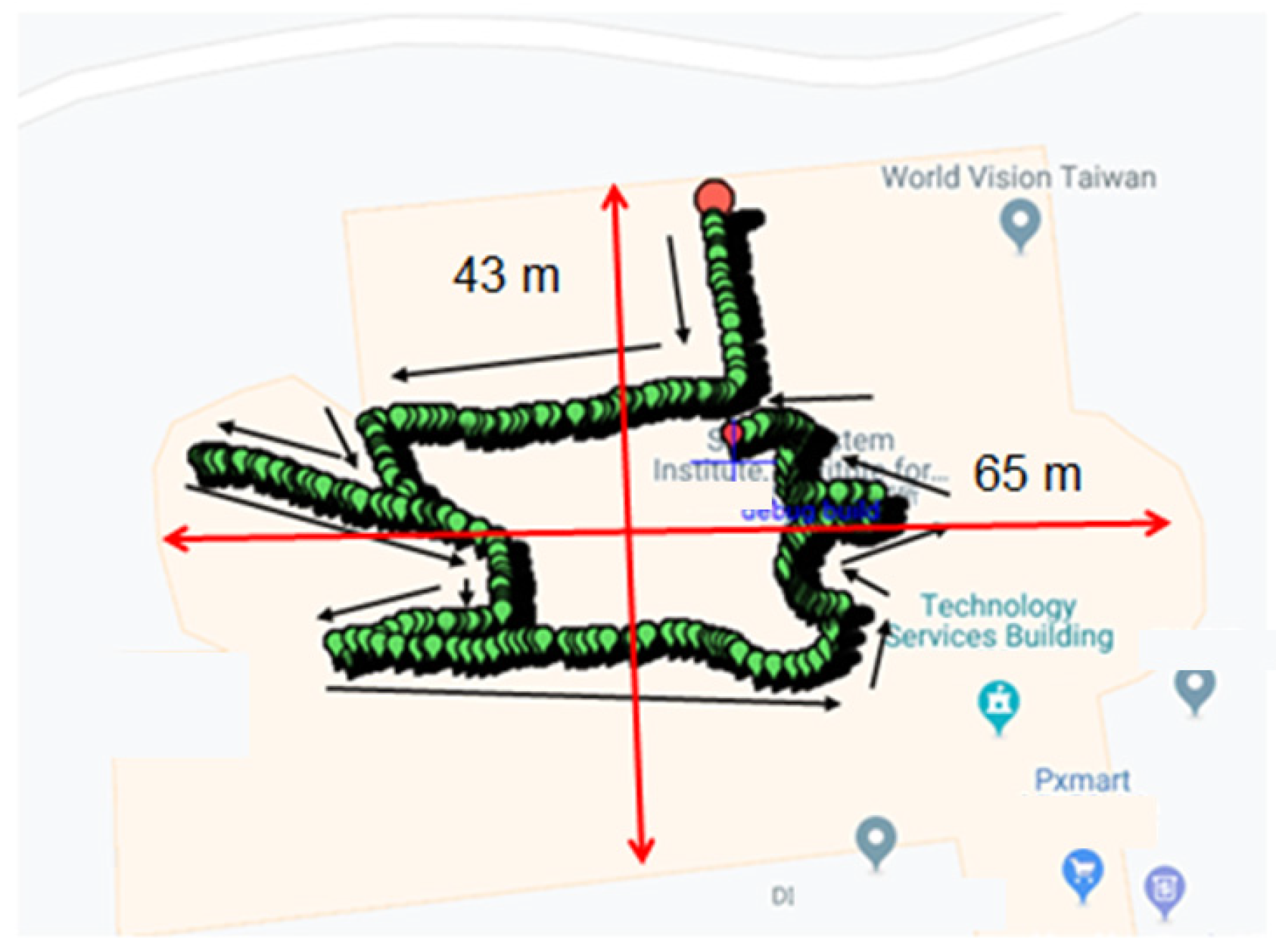
The relationship parameters between geomagnetism and coordinates collected by the GeoMag-Coordinate model are used to calculate the target latitude and longitude through the coordinate estimator. We conducted tests in different locations and on different floors, and the results showed that the location latitude and longitude could be estimated incrementally by using the change in the geomagnetic field when moving. We tested in an office of 43 × 65 m, in which the length of the aisle circle was about 188 m. System accuracy can reach 0.8~1.5 m. The results are displayed on Google Maps, as shown in Figure 12.
In Figure 7, the person starts to move from the big red anchor, where the movement direction is indicated by the black arrow, and continues to move to the small red anchor, where they stop. The trajectory map of our walk around the aisle in the office is consistent with the aisle layout of the office.
In this paper, the system uses Google Maps to verify that personnel locations can be displayed during emergencies without indoor maps. If there is an indoor map, the indoor map can also be used for location display in the future.
4.3. Comparison with Other Systems
In this paper, we compared two systems that use geomagnetic strength positioning with smartphones: (1) dynamic route prediction with the magnetic field strength for indoor positioning [35]; for convenience, we refer to this as DRP. This paper introduces a novel feature that allows the positioning system to predict in advance the walking route. (2) Smartphone-Based Indoor Localization with Integrated Fingerprint Signal [36]; for convenience, we call this CSMS. This study proposes an integrated channel state information (CSI) and magnetic field strength (MFS) localization method (CSMS). Furthermore, this paper presents a smartphone-based sub-meter-accuracy indoor localization method that integrates CSI and MFS. Our system Intelligent Geomagnetic Indoor Positioning System is referred to as IGIPS for convenience; the system integrates a GY-273 geomagnetic sensor with a Hecha HMC5883L. The comparison is shown in Table 5.
Although DRP and CSMS do not require additional facilities, they need pre-build fingerprinting databases for position estimation, and establishing and maintaining a fingerprinting database is time-consuming and laborious work.
In terms of the system’s test results, our technique can be applied to indoor positioning. Several aspects of this approach are worth exploring.
- (1)
- System Availability: The system does not need to preset any positioning facilities to perform indoor positioning, nor does it need to pre-establish any positioning map. System introduction is easy. Especially in disaster relief, as long as it is within the communication range of the command vehicle (LOS 100 km), the commander can monitor the position of the person wearing the sensor.
- (2)
- Critical time limit: Timeliness is the first priority for disaster relief tasks, and the system must be ready. The wireless base station of this system is set up on the command vehicle, and it is very convenient to have communication available as soon as the command vehicle arrives at the scene.
5. Conclusions
In the past, there has been varying indoor positioning research, but most require knowledge of building infrastructure in advance or the establishment of complex and huge databases to assist in positioning. This experiment verifies that it is possible to use the difference in magnetic strength between two points for indoor positioning, which is different from previous applications using various localization facilities for positioning. Using localization facilities for indoor positioning not only requires money and time to set up facilities but also requires manpower. Creating image databases for positioning is also time-consuming and labor-intensive. In this paper, we discovered geomagnetic properties and developed algorithms for indoor positioning to solve indoor positioning needs.
- (1)
- Problems solved:
- We developed a practical algorithm that resists the influence of the external environment on geomagnetism and estimates latitude and longitude successfully.
- Based on ubiquitous geomagnetic properties, the indoor position system does not require any infrastructure assistance.
- The indoor positioning accuracy of this system is about 0.8~1.5 m.
- (2)
- Benefits:
- We designed a geomagnetic indoor positioning system without any infrastructure assistance.
- We integrate Google Maps to display subjects’ current location and trajectory.
- The indoor positioning system can be applied to disaster relief.
- The geomagnetic indoor positioning system can be integrated with automatic guided vehicle systems (AGVs) in factories and location-based service (LBS) in shopping malls and underground streets.
We believe this is the beginning of another option for indoor positioning applications, and there is no need to preset any positioning facilities. In the future, this tool should be able to be integrated with more application systems and provide more services.
Author Contributions
Conceptualization, Y.-H.K. and E.H.-K.W.; methodology, Y.-H.K. and E.H.-K.W.; software, Y.-H.K.; validation, E.H.-K.W.; formal analysis, E.H.-K.W.; investigation, Y.-H.K.; resources, Y.-H.K.; data curation, Y.-H.K.; writing—original draft preparation, Y.-H.K.; writing—review and editing, Y.-H.K. and Eric Hsiao-Kuang; visualization, Y.-H.K.; supervision, E.H.-K.W.; project administration, E.H.-K.W. All authors have read and agreed to the published version of the manuscript.
Funding
This research received no external funding.
Data Availability Statement
The datasets generated and/or analyzed during the current study are available at the following drive.google.com repository: https://drive.google.com/drive/folders/1FVCnNC19OGQ6NSfjBT9rfL_85JZTU48E (accessed on 1 April 2023).
Acknowledgments
This work was supported by the Institute for Information Industry and K-BEST Technology INC.
Conflicts of Interest
The authors declare no conflict of interest.
References
- Basiri, A.; Lohan, E.S.; Moore, T.; Winstanley, A.; Peltola, P.; Hill, C.; Amirian, P.; Silva, P.F. Indoor Location Based Services challenges, requirements and usability of current solutions. Comput. Sci. Rev. 2017, 24, 1–12. [Google Scholar] [CrossRef]
- Kok, M.; Hol, J.D.; Schön, T.B. Indoor Positioning Using Ultrawideband and Inertial Measurements. IEEE Trans. Veh. Technol. 2015, 64, 1293–1303. [Google Scholar] [CrossRef]
- Wang, H.; Gao, K.; Lyu, H. Survey of high-precision localization and the prospect of future evolution. J. Commun. 2021, 42, 198–210. [Google Scholar]
- Oyekanlu, E.A.; Smith, A.C.; Thomas, W.P.; Mulroy, G.; Hitesh, D.; Ramsey, M.; Kuhn, D.J.; Mcghinnis, J.D.; Buonavita, S.C.; Looper, N.A.; et al. A Review of Recent Advances in Automated Guided Vehicle Technologies: Integration Challenges and Research Areas for 5G-Based Smart Manufacturing Applications. IEEE Access 2020, 8, 202312–202353. [Google Scholar] [CrossRef]
- Liu, K.; Liu, X.; Li, X. Guoguo: Enabling fine-grained indoor localization via smartphone. In Proceedings of the MobiSys ‘13: Proceeding of the 11th Annual International Conference on Mobile Systems, Applications, and Services, Taipei, Taiwan, 25–28 June 2013; pp. 235–248. [Google Scholar] [CrossRef]
- Joshi, K.; Hong, S.; Katti, S. PinPoint: Localizing Interfering Radios. NSDI 2013, 10, 2482626–2482651. [Google Scholar]
- Xiong, J.; Jamieson, K. Arraytrack: A fine-grained indoor location system. In Proceedings of the 10th USENIX Symposium on Networked Systems Design and Implementation (NSDI ’13), Lombard, IL, USA, 2–5 April 2013. [Google Scholar]
- Ouyang, G.; Abed-Meraim, K. A Survey of Magnetic-Field-Based Indoor Localization. Electronics 2022, 11, 864. [Google Scholar] [CrossRef]
- Ashraf, I.; Bin Zikria, Y.; Hur, S.; Park, Y. A Comprehensive Analysis of Magnetic Field Based Indoor Positioning With Smartphones: Opportunities, Challenges and Practical Limitations. IEEE Access 2020, 8, 228548–228571. [Google Scholar] [CrossRef]
- Li, F.; Zhao, C.; Ding, G.; Gong, J.; Liu, C.; Zhao, F. A reliable and accurate indoor localization method using phone inertial sensors. In Proceedings of the UbiComp ‘12: Proceedings of the 2012 ACM Conference on Ubiquitous Computing, Pittsburgh, PA, USA, 5–8 September 2012; pp. 421–430. [Google Scholar]
- Shu, Y.; Li, Z.; Karlsson, B.; Lin, Y.; Moscibroda, T.; Shin, K. Incrementally-deployable Indoor Navigation with Automatic Trace Generation. In Proceedings of the IEEE INFOCOM 2019–IEEE Conference on Computer Communications, Paris, France, 29 April–2 May 2019; pp. 2395–2403. [Google Scholar] [CrossRef]
- Shu, Y.; Shin, K.G.; He, T.; Chen, J. Last-Mile Navigation Using Smartphones. In Proceedigns of the MobiCom ‘15: Proceedings of the 21st Annual International Conference on Mobile Computing and Networking, Paris, France, 7–11 September 2015. [Google Scholar] [CrossRef]
- Ashraf, I.; Hur, S.; Park, Y. mPILOT-magnetic field strength based pedestrian indoor localization. Sensors 2018, 18, 2283. [Google Scholar] [CrossRef] [PubMed]
- Zou, Y.; Wang, G.; Wu, K.; Ni, L.M. Smartscanner: Know more in walls with your smartphone! IEEE Trans. Mob. Comput. 2015, 15, 2865–2877. [Google Scholar] [CrossRef]
- Xiao, L.; Behboodi, A.; Mathar, R. A Deep Learning Approach to Fingerprinting Indoor Localization Solutions. In Proceedings of the 2017 27th International Telecommunication Networks and Applications Conference (ITNAC), Melbourne, VIC, Australia, 22–24 November 2017. [Google Scholar]
- Wu, J.; Zhou, Z.; Chen, J.; Fourati, H.; Li, R. Fast complementary filter for attitude estimation using low-cost MARG sensors. IEEE Sens. J. 2016, 16, 6997–7007. [Google Scholar] [CrossRef]
- Lee, N.; Han, D. Magnetic indoor positioning system using deep neural network. In Proceedings of the 2017 International Conference on Indoor Positioning and Indoor Navigation (IPIN), Sapporo, Japan, 18–21 September 2017. [Google Scholar]
- Kok, M.; Schon, T.B. Magnetometer Calibration Using Inertial Sensors. IEEE Sens. J. 2016, 16, 5679–5689. [Google Scholar] [CrossRef]
- Soken, H.E. A survey of calibration algorithms for small satellite magnetometers. Measurement 2018, 122, 417–423. [Google Scholar] [CrossRef]
- Vasconcelos, J.F.; Elkaim, G.; Silvestre, C.; Oliveira, P.; Cardeira, B. Geometric Approach to Strapdown Magnetometer Calibration in Sensor Frame. IEEE Trans. Aerosp. Electron. Syst. 2011, 47, 1293–1306. [Google Scholar] [CrossRef]
- Wu, Y.; Shi, W. On calibration of three-axis magnetometer. IEEE Sens. J. 2015, 15, 6424–6431. [Google Scholar] [CrossRef]
- Ashraf, I.; Hur, S.; Park, Y. BLocate: A Building Identification Scheme in GPS Denied Environments Using Smartphone Sensors. Sensors 2018, 18, 3862. [Google Scholar] [CrossRef] [PubMed]
- Hanley, D.; Faustino, A.B.; Zelman, S.D.; Degenhardt, D.A.; Bret, T. MagPIE: A Dataset for Indoor Positioning with Magnetic Anomalies. In Proceedings of the 2017 International Conference on Indoor Positioning and Indoor Navigation, Sapporo, Japan, 18–21 September 2017. [Google Scholar]
- Torres-Sospedra, J.; Rambla, D.; Montoliu, R.; Belmonte, O.; Huerta, J. UJIIndoorLoc-Mag: A New Database for Magnetic Field-Based Localization Problems. In Proceedings of the International Conference on Indoor Positioning and Indoor Navigation (IPIN), Banff, AB, Canada, 13–16 October 2015; pp. 1–10. [Google Scholar]
- Tóth, Z.; Tamás, J. Miskolc IIS hybrid IPS: Dataset for hybrid indoor positioning. In Proceedings of the 2016 26th International Conference Radioelektronika (RADIOELEKTRONIKA), Kosice, Slovakia, 19–20 April 2016; pp. 408–412. [Google Scholar]
- Wang, Q.; Luo, H.; Wang, J.; Sun, L.; MaRecent, Z.; Fu, M.; Zhang, C.; Zhao, F. Recent Advances in Pedestrian Navigation Activity Recognition: A Review. IEEE Sens. J. 2022, 22, 7499–7518. [Google Scholar] [CrossRef]
- Nessa, A.; Adhikari, B.; Hussain, F.; Fernando, X.N. A Survey of Machine Learning for Indoor Positioning. IEEE Access 2020, 8, 214945–214965. [Google Scholar] [CrossRef]
- Honeywell. 3-Axis Digital Compass IC HMC5883L. Available online: https://cdn-shop.adafruit.com/datasheets/HMC5883L_3-Axis_Digital_Compass_IC.pdf (accessed on 1 April 2023).
- Xu, X.; Lin, L. Geomagnetic Fingerprint Maps for Indoor Positioning. In Proceedings of the 2017 International Conference on Cyber-Enabled Distributed Computing and Knowledge Discovery, Nanjing, China, 12–14 October 2017. [Google Scholar]
- Cao, W. Geomagnetic Signal Detecting based on Magnetoresistive Sensor. Master’s Thesis, Huazhong University of Science & Technology, Wuhan, China, 2007. [Google Scholar]
- Bowen, K. Arduino Interactive Design; Acer Peak Information Co., Ltd.: Hong Kong, 2014; ISBN 9789863471004. [Google Scholar]
- Waheed, A. Analysis of Moving Average Convergence Divergence (MACD) as a Tool of Equity Trading at the Karachi Stock Exchange. Master’s Thesis, Blekinge Tekniska Högskola, Karlskrona, Sweden, 2013. [Google Scholar]
- C# Corner. Available online: https://www.c-sharpcorner.com/blogs/integrate-google-map-in-c-sharp (accessed on 1 April 2023).
- Asmag. Safety Monitoring and Alarm System for Firefighters. Available online: https://www.asmag.com.tw/suppliers/productcontent.aspx?co=k-best&id=1788 (accessed on 1 April 2023).
- Nguyen, K.A.; Luo, Z. Dynamic route prediction with the magnetic field strength for indoor positioning. Int. J. Wirel. Mob. Comput. 2017, 12, 16. [Google Scholar] [CrossRef]
- Li, P.; Yang, X.; Yin, Y.; Gao, S.; Niu, Q. Smartphone-Based Indoor Localization with Integrated Fingerprint Signal. IEEE Access 2020, 8, 33178–33187. [Google Scholar] [CrossRef]
Figure 1.
The three axes of geomagnetism.
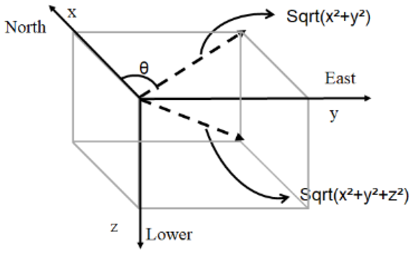
Figure 2.
System overview.

Figure 3.
Geomagnetic strength.
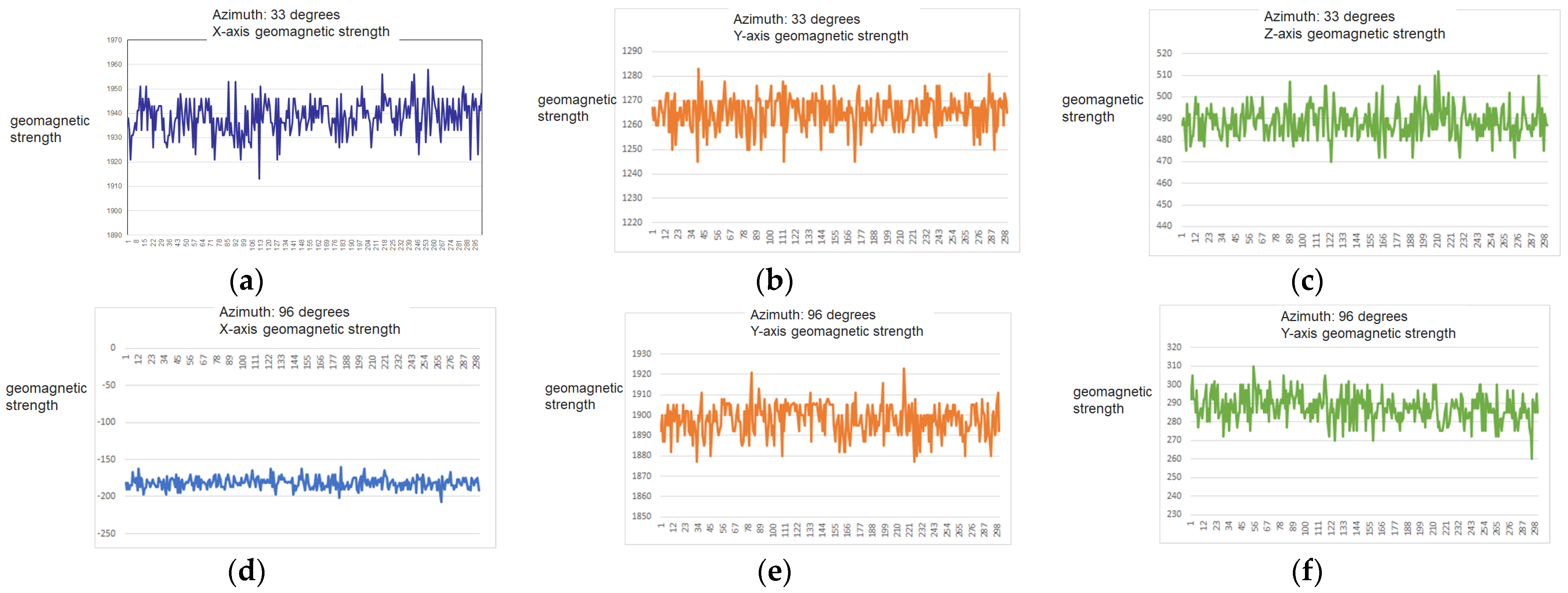
Figure 4.
Magnetic interference.
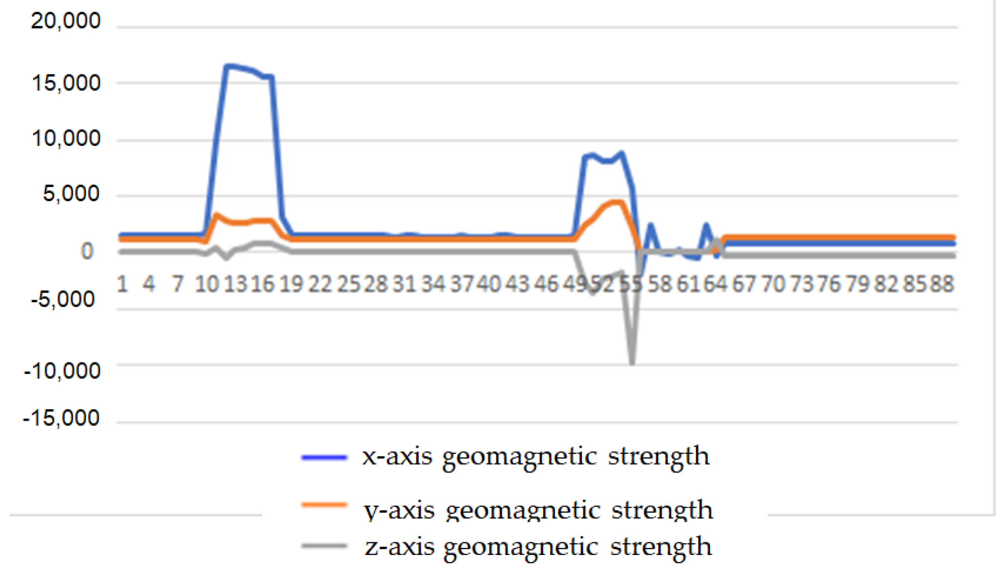
Figure 5.
(a) 2nd floor magnetism. (b) 7th floor magnetism.

Figure 6.
(a) removal of 5% of data (b) removal of 15% of data (c) removal of 30% of data.
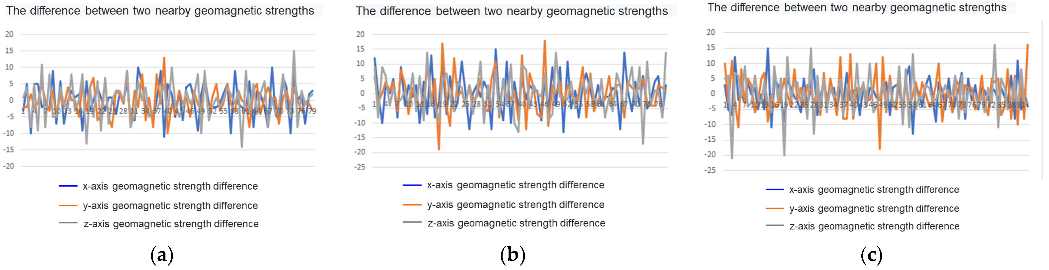
Figure 7.
Geomagnetic noise filter.
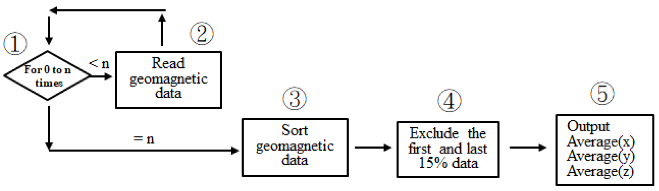
Figure 8.
Indoor positioning tracking.
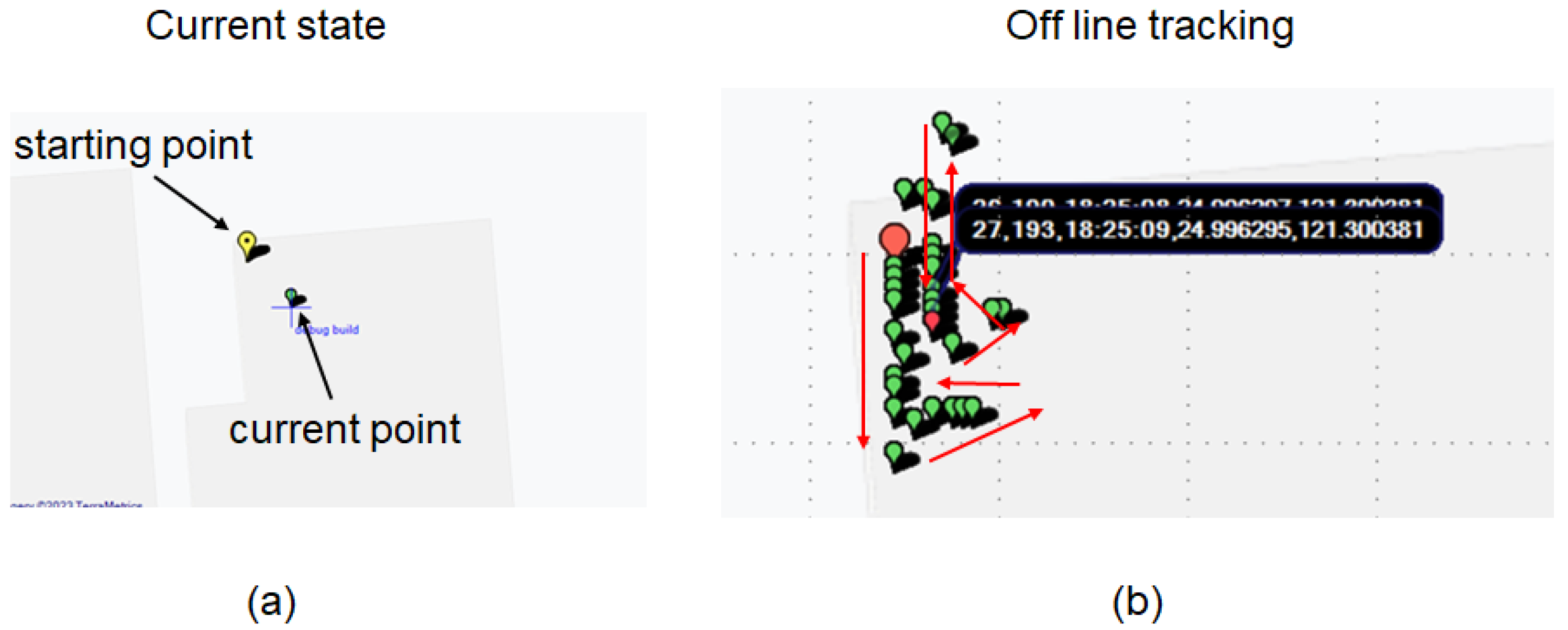
Figure 9.
Super TaiRa wireless communication in mountain environment.

Figure 10.
Geomagnetic sensing integrated with Super TaiRa.
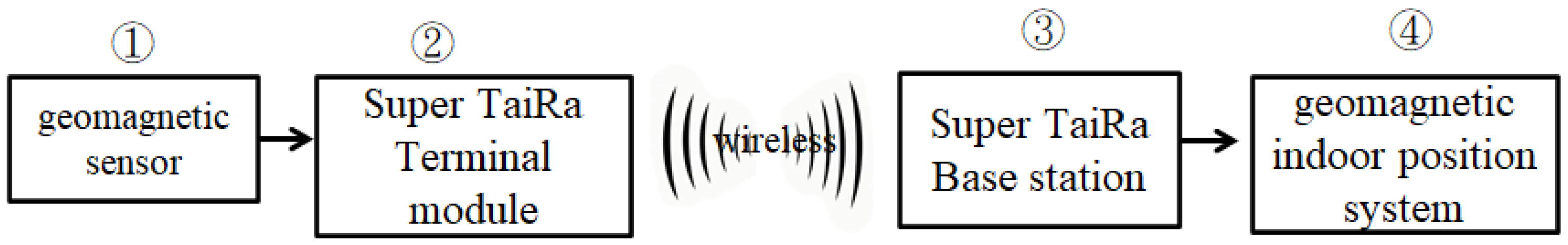
Figure 11.
Filtered turbulence.

Figure 12.
Trajectory diagram.

Table 1.
Take 17 pieces of gray background data.
| No | x | y | z | Sqrt(x² + y² + z²) |
|---|---|---|---|---|
| 1 | 885 | −793 | 92 | 1191 |
| 2 | 907 | −773 | 92 | 1195 |
| 3 | 907 | −776 | 92 | 1197 |
| 4 | 905 | −778 | 105 | 1198 |
| 5 | 915 | −768 | 102 | 1198 |
| 6 | 910 | −773 | 112 | 1199 |
| 7 | 905 | −783 | 85 | 1199 |
| 8 | 912 | −776 | 87 | 1200 |
| 9 | 907 | −781 | 97 | 1200 |
| 10 | 905 | −783 | 105 | 1201 |
| 11 | 915 | −773 | 92 | 1201 |
| 12 | 920 | −768 | 90 | 1201 |
| 13 | 910 | −783 | 82 | 1203 |
| 14 | 917 | −773 | 110 | 1204 |
| 15 | 920 | −771 | 100 | 1204 |
| 16 | 907 | −786 | 105 | 1204 |
| 17 | 915 | −778 | 95 | 1204 |
| 18 | 912 | −781 | 102 | 1205 |
| 19 | 917 | −776 | 102 | 1205 |
| 20 | 922 | −773 | 107 | 1207 |
| 21 | 915 | −783 | 95 | 1208 |
| 22 | 910 | −791 | 92 | 1209 |
| 23 | 920 | −781 | 87 | 1209 |
| 24 | 920 | −781 | 90 | 1210 |
| 25 | 917 | −793 | 92 | 1215 |
Table 2.
Static state geomagnetism variation.
| θ | x | y | z | ∆x | ∆y | ∆z |
|---|---|---|---|---|---|---|
| 288 | 747 | −2257 | −162 | 2 | −7 | 3 |
| 288 | 749 | −2264 | −159 | 5 | 2 | 5 |
| 288 | 754 | −2262 | −154 | −6 | −3 | −1 |
| 288 | 748 | −2265 | −155 | 0 | 1 | −3 |
| 288 | 748 | −2264 | −158 | 3 | 0 | 4 |
| 288 | 751 | −2264 | −154 | −1 | −2 | 7 |
Table 3.
Moving state geomagnetism variation.
| θ | x | y | z | ∆x | ∆y | ∆z |
|---|---|---|---|---|---|---|
| 346 | 1231 | −315 | −357 | 178 | −294 | 151 |
| 337 | 1409 | −609 | −206 | −673 | −924 | −35 |
| 296 | 736 | −1533 | −241 | −866 | 84 | −393 |
| 265 | −130 | −1449 | −634 | −284 | 262 | −111 |
| 251 | −414 | −1187 | −745 | −133 | 336 | −45 |
| 237 | −547 | −851 | −790 | 832 | −546 | 856 |
| 282 | 285 | −1397 | 66 | 834 | 1325 | −97 |
Table 4.
Super TaiRa features.
| Item | Super TaiRa | LoRa |
|---|---|---|
| Frequency Range | 410~990 MHz | EU 868,433 MHz US 915 MHz AS 430 MHz |
| Modulation | GFSK + CSS | GFSK + CSS |
| Data Rate | DSSS: 10 bps~10 Kbps GMSK: 1 Kbps~250 Kbps | 0.3 kbps to 50 kbps |
| Spreading factor | 6 dB~12 dB | 7 dB~12 dB |
| Tx Power output | Up to 20 dBm | Up to 14 dBm |
| Rx Sensitivity | −118~−136 dBm @ Channel BW = 125 KHz −115~−133 dBm @ Channel BW = 250 KHz −112~−130 dBm @ Channel BW = 500 KHz @ 1% PER | −123~−136 dBm@ Channel BW = 125 KHz −120~−133 dBm@ Channel BW = 250 KHz −116~−130 dBm @ Channel BW = 500 KHz |
| Transmission | Up to 100 km @LOS | Up to 20 km @LOS |
GFSK: Gaussian Frequency Shift Keying. CSS: Carrier Signal Strength. DSSS: Direct Sequence Spread Spectrum. GMSK: Gaussian Minimum Shift Keying. BW: Bandwidth. PER: Packet Error Rate. LOS: Line of Sight. Tx: Transmit. Rx: Receive.
Table 5.
Comparison with other systems.
| System | Sensing Device | Additional Facilities | Pre-Built Fingerprinting Database | Construction/Maintenance Costs | Positioning Accuracy |
|---|---|---|---|---|---|
| DRP | Smartphone | No | Yes | High | 2.2 m |
| CSMS | Smartphone | No | Yes | High | 0.5 m |
| IGIPS | GY-273 geomagnetic sensor | No | No | Low | 0.8~1.5 m |
Disclaimer/Publisher’s Note: The statements, opinions and data contained in all publications are solely those of the individual author(s) and contributor(s) and not of MDPI and/or the editor(s). MDPI and/or the editor(s) disclaim responsibility for any injury to people or property resulting from any ideas, methods, instructions or products referred to in the content. |
© 2023 by the authors. Licensee MDPI, Basel, Switzerland. This article is an open access article distributed under the terms and conditions of the Creative Commons Attribution (CC BY) license (https://creativecommons.org/licenses/by/4.0/).
Share and Cite
MDPI and ACS Style
Kuo, Y.-H.; Wu, E.H.-K. Intelligent Geomagnetic Indoor Positioning System. Electronics 2023, 12, 2227. https://doi.org/10.3390/electronics12102227
AMA Style
Kuo Y-H, Wu EH-K. Intelligent Geomagnetic Indoor Positioning System. Electronics. 2023; 12(10):2227. https://doi.org/10.3390/electronics12102227
Chicago/Turabian StyleKuo, Yen-Hui, and Eric Hsiao-Kuang Wu. 2023. "Intelligent Geomagnetic Indoor Positioning System" Electronics 12, no. 10: 2227. https://doi.org/10.3390/electronics12102227
Note that from the first issue of 2016, this journal uses article numbers instead of page numbers. See further details here.