Article

Enhancing Photovoltaic Efficiency with the Optimized Steepest Gradient Method and Serial Multi-Cellular Converters

1
Department of Electrical Engineering, University Akli Mohand Oulhadj-Bouria, Rue Drissi Yahia Bouira, Bouïra 10000, Algeria
2
Electrical Engineering Advanced Technology Laboratory (LATAGE), Tizi Ouzou 15000, Algeria
3
Automated Systems & Soft Computing Lab (ASSCL), Prince Sultan University, Riyadh 11586, Saudi Arabia
4
College of Computer & Information Sciences, Prince Sultan University, Riyadh 11586, Saudi Arabia
5
Faculty of Computers and Artificial Intelligence, Benha University, Benha 13518, Egypt
6
Department of ICT and Natural Sciences, Norwegian University of Science and Technology, Larsgårdsve-gen, 2, 6009 Ålesund, Norway
7
Faculty of Engineering, Cairo University, Giza 12613, Egypt
*
Authors to whom correspondence should be addressed.
Electronics 2023, 12(10), 2283; https://doi.org/10.3390/electronics12102283
Submission received: 15 April 2023 / Revised: 11 May 2023 / Accepted: 16 May 2023 / Published: 18 May 2023
(This article belongs to the Special Issue Solar-Forecasting-Assisted Photovoltaic Power System Control)

Abstract

:
Many methods have been developed to aid in achieving the maximum power point (MPP) generated by PV fields in order to improve photovoltaic (PV) production. The optimized steepest gradient technique (OSGM), which is used to extract the maximum power produced by a PV field coupled to a multicell series converter, is one such promising methodology. The OSGM uses the power function’s first and second derivatives to find the optimal voltage ( V p v ) and converge to the voltage ( V r e f ) that secures the MPP. The mathematical model was developed in Matlab/Simulink, and the MPPT algorithm’s performance was evaluated in terms of reaction time, oscillations, overshoots, and stability. The OSGM has a faster response time, fewer oscillations around the MPP, and minimal energy loss. Furthermore, the numerical calculation of the gradient and Hessian of the power function enables accurate modeling, improving the system’s precision. These findings imply that the OSGM strategy may be a more efficient way of obtaining MPP for PV fields. Future research can look into the suitability of this method for different types of PV systems, as well as ways to improve the algorithm’s performance for specific applications.

1. Introduction

Over three-quarters of the world’s energy consumption is derived from fossil fuels. However, these energy sources—gas, oil, and coal, which will run out in the coming decades—are now known to cause air pollution and an increase in the greenhouse effect, resulting in global warming. Organizations are pushing for the development of greener energy sources in response to rising global demand. Alternative energy sources for power include solar, wind, and hydroelectric sources. Furthermore, distribution networks cannot serve the entire global population; whether in the mountains or on an island, in the least populated areas or in the middle of the desert, difficult-to-access or very isolated sites cannot always be connected to the grid due to technical constraints or a lack of economic viability. Renewable energy sources, which may be scaled for residential use, are ideal for providing power in remote or micro-grid locations. They are frequently paired with batteries, which store excess energy output or compensate for transient power shortages during peak consumption periods. The worldwide need for energy is continuously expanding, and as traditional energy sources, such as gas, oil, and coal, deplete, the need for cleaner and renewable energy sources will grow [1,2,3]. Solar energy is one of the most effective and least polluting renewable energy sources available. PV systems, which convert solar energy into electrical energy, are extensively employed in a variety of applications, ranging from modest household systems to large-scale power plants [4,5,6,7,8]. However, the non-linearity of the photovoltaic generator results in a low energy conversion rate, which is a major disadvantage of the PV system. To address this issue, researchers are working on maximum power point tracking (MPPT) algorithms that aid in maintaining maximum power output despite fluctuations in sunshine and temperature. MPPT algorithms are critical for increasing the amount of energy generated by solar systems [9,10,11,12,13,14,15]. MPPT algorithms are classified into two types: dependent and independent. Dependent algorithms make use of parameter databases to maximize the power of the photovoltaic system [16]. These methods make use of intelligent controllers, such as artificial neural networks (ANNs) [17], adaptive neuro-fuzzy inference systems (ANFISs) [18,19], and fuzzy logic controllers (FLCs). FLC is the easiest to construct among these controllers, but it has several drawbacks, such as rule definition, algorithm complexity, and reaction time to reach the maximum power point [20,21,22,23]. On the other hand, independent MPPT algorithms do not require knowledge of the PV system model and can be implemented without any prior knowledge of the system. These algorithms are based on mathematical models and are often classified as perturb and observe (P&O), incremental conductance (INC), or hill climbing (HC) methods. These algorithms use the voltage and current measurements to estimate the PV system’s maximum power point.
Recent energy research intends to build better MPPT algorithms to improve the performance of solar systems [24,25,26]. These algorithms provide faster reaction, fewer oscillations around the maximum power point, and reduced energy loss. The development of these algorithms is critical in order to fulfill the rising demand for energy while lowering prices and creating a sustainable environment. MPPT (maximum power point tracking) is a technique for optimizing the power output of a photovoltaic (PV) system under different conditions by continually adjusting the operating point of the PV panels to the maximum power point (MPP). This allows the system to harvest the greatest amount of electricity from the solar panels, enhancing the system’s total efficiency. MPPT algorithms are divided into two types: open-loop and closed-loop approaches. Open-loop approaches, such as the perturb and observe (P&O) method, are based on the observation of the solar panel’s output current and voltage and alter the operating point correspondingly. Closed-loop approaches, such as the incremental conductance (IC) method, employ a feedback loop to change the operating point continuously until the maximum power point is attained [23,27,28]. The study in [29] compares several MPPT approaches, such as perturb and observe, incremental conductance, and fractional open circuit voltage. The authors rate each technique’s performance based on parameters such as convergence time, steady-state oscillation, and tracking efficiency. Ref. [30] presents a thorough examination of two common MPPT strategies, perturb and observe and incremental conductance, covering their fundamental concepts, benefits, and drawbacks. The authors also address current advancements and changes to these strategies. The authors in [31] provide a detailed discussion of several MPPT strategies, including old methods, such as perturb and observe, incremental conductance, and hill climbing, as well as modern techniques like artificial neural networks and fuzzy logic. Each approach is evaluated by the authors based on variables such as convergence speed, steady-state oscillation, and efficacy in dealing with partial shading. The work in [32] reviews many MPPT strategies for PV systems, such as perturb and observe, incremental conductance, and other advanced techniques, such as model reference adaptive control and sliding mode control. Each approach is evaluated by the authors based on variables such as convergence speed, steady-state oscillation, and efficacy in dealing with partial shading. In [33], the authors offered an MPPT technique based on an artificial neural network (ANN) for solar applications. The suggested technique estimates the ideal duty cycle that maximizes PV output power using a neural network model. A dataset of PV power and voltage values recorded under various climatic circumstances is used to train the ANN model.
The study [34] describes an MPPT control technique for solar systems based on an adaptive neuro-fuzzy inference system (ANFIS). The ANFIS model is trained to predict the ideal voltage for maximizing PV output power. To increase the performance of the ANFIS controller, the suggested technique additionally employs an updated antlion optimizer (ALO) algorithm. In the study [35], an enhanced maximum power point tracking (EMPPT) method for solar systems is proposed. To estimate the best voltage that maximizes PV output power, the suggested technique employs an artificial bee colony (ABC) optimization algorithm. To increase the performance of the EMPPT controller, the ABC algorithm is integrated with a neural network. The hybrid fuzzy logic and artificial neural network based maximum power point tracking for photovoltaic systems is proposed in [36] to predict the ideal duty cycle that maximizes the PV output power. To increase the performance of the MPPT controller, the fuzzy logic controller is paired with an ANN. The study [37] offers a novel MPPT approach for solar power systems based on the cuckoo search algorithm (CSA) and ANFIS in the study. The suggested technique estimates the best voltage that maximizes the PV output power using the CSA algorithm. To increase the performance of the MPPT controller, the CSA algorithm is integrated with an ANFIS model.
This paper describes how to use the optimized steepest gradient technique (OSGM) in conjunction with a multicellular series converter to maximize the power output of a photovoltaic (PV) field. The OSGM is an independent approach for tracking the maximum power point (MPP) that allows for precise and efficient PV system operation. Unlike other MPPT methods that utilize a constant or variable step to update the voltage or duty cycle, the OSGM uses an optimized step value based on the power function’s second-order approximation with regard to the voltage Vpv to update the voltage value to achieve the reference voltage (Vref). The suggested OSGM technique is evaluated using MATLAB/SIMULINK simulation under varied solar radiation conditions. The findings reveal that the OSGM algorithm is more effective and precise than other approaches for obtaining MPP. The reaction time is faster, and there are fewer oscillations around the MPP, which result in less energy waste. Furthermore, the numerical calculation of the gradient and Hessian of the power function allows for accurate modeling, which improves system precision.
The MPPT approach is critical for sustaining maximum power production regardless of changes in sunshine and temperature. The OSGM approach provides a viable alternative for improving the energy quality delivered by solar fields. This strategy is especially appropriate for isolated or micro-grid places when distribution networks are unable to offer energy to the full world population, owing to technical constraints or a lack of economic feasibility.
The following is the paper’s structure: Section 1 discusses the related work. Section 2 shows the proposed system’s presentation and modeling. Section 3 discusses the proposed MPPT algorithm (OSGM), and Section 4 offers the research work’s conclusion.

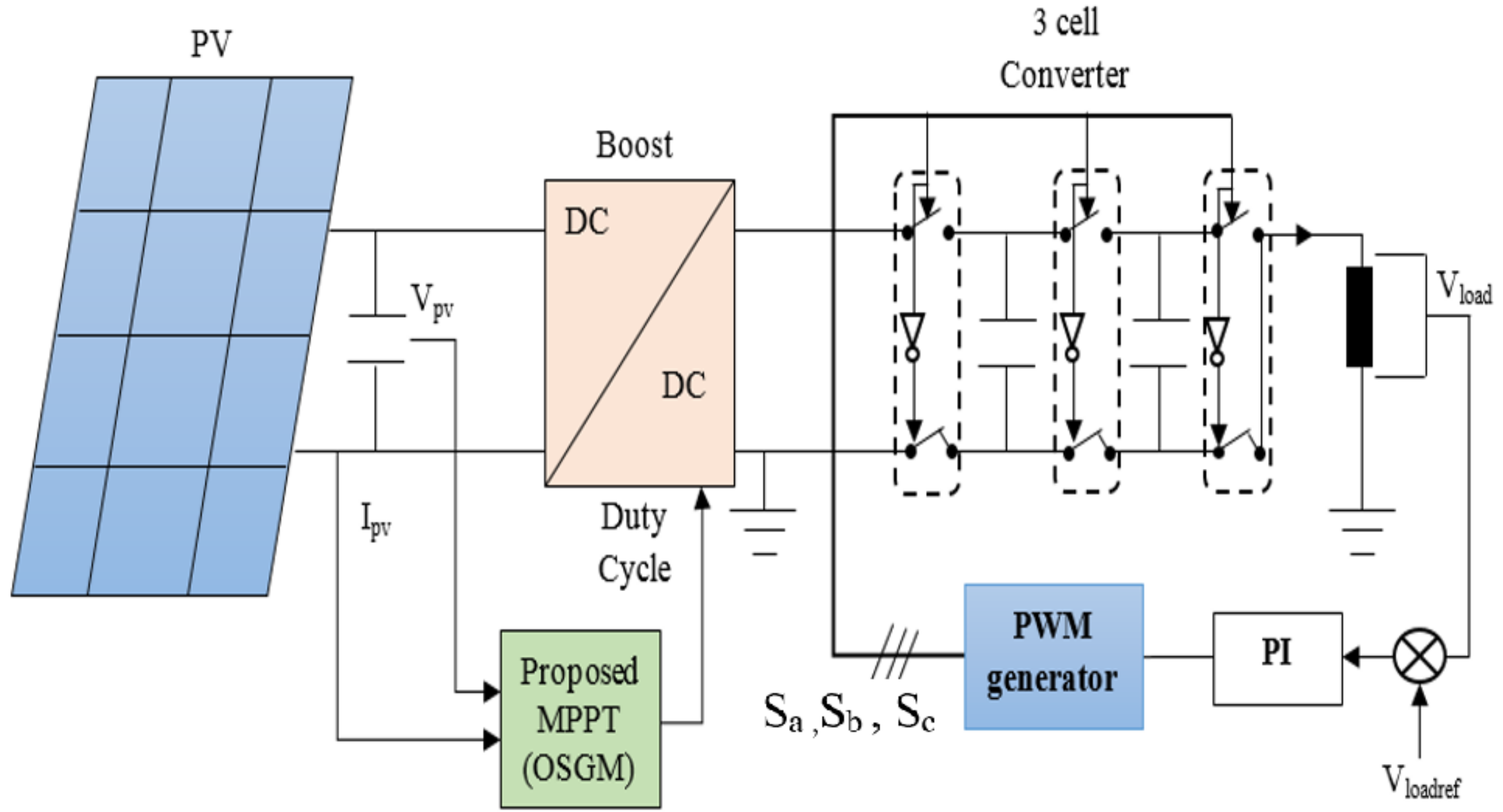
2. Presentation and Modeling of the Proposed System

As shown in Figure 1, the proposed system comprises a SHELL SP75 PV generator coupled to a DC load via a multicellular series converter made up of three cells. This converter increases the quality of energy sent to the load, whereas a boost converter extracts the highest power. A multicellular inverter is required between the boost converter and the load for AC loads, resulting in a two-stage power conversion process. If the energy generated by the solar system exceeds the demand of the load, the extra energy is sent back into the electrical network and consumed by grid users.

2.1. Mathematical Model of the Photovoltaic System

The single-diode photovoltaic cell model was used for this study because it is a widely used and simple model that accurately reflects the behavior of a solar cell under varied operational conditions. The following equations reflect the conventional I-V characteristic of a solar array:
V = V o c + I s c R s I R s h
I = I p h I 0 ( e ( V + I R s h ) / ( n V t ) )
The widely used and basic single-diode model of the solar cell was used for this study because it properly captures the cell’s behavior under varied operating situations. The conventional I-V characteristic equation of a solar array includes the following variables: V for the terminal voltage of the cell, I for the current through the cell, V o c for the open circuit voltage, I s c for the short circuit current, R s for the series resistance, R s h for the shunt resistance, I p h for the photocurrent, I 0 for the reverse saturation current, n for the ideality factor, and V t for the thermal voltage. By utilizing this model, important parameters (as shown in Table 1) affecting the photovoltaic cell’s performance, such as temperature, radiation, load resistance, and internal resistance of the cell, can be represented. This model can provide predictions of the solar cell’s performance under different conditions and can optimize the system performance by adjusting various parameters.

2.2. Mathematical Model of Boost Converter

The boost converter shown in Figure 2 is a popular form of converter made up of two energy storage components, the inductor L and the capacitor C. The inductor stores energy in a magnetic field during switch closure, and when the switch opens, it distributes energy to the load. The capacitor contributes to smoothing the output voltage and reducing ripple. The switch state changes between on and off states in response to the control signal u. The on state is in the time interval of t ϵ [ 0 , D T ] , while the off state is in t ϵ [ D T , ( 1 D ) T ] , where D is the duty cycle. The duty cycle represents the ratio of time that the switch is closed to the entire switching period [38].
  • Switch On (u = 1)
    V p v = L d I L d t
    0 = C d V d c d t + I d c
  • Switch Off (u = 0)
    V p v = L d I L d t + V d c
    I L = C d V d c d t + I d c
The two above-mentioned models of the converter, the continuous conduction mode (CCM) and the discontinuous conduction mode (DCM), can be gathered and represented in a single set of equations that describes the behavior of the converter under different operating conditions:
V p v = L d I L d t + ( 1 u ) V d c
I L ( 1 u ) = C d V d c d t + I d c
By substituting variable u with its average value D (duty cycle) over a period T = 1 / f , where D is defined as the ratio of the time the switch is on ( T O N ) to the total period (T), we can obtain the average model of the converter:
V p v m = 1 L d I L m d t + ( 1 D ) V d c m
I L m ( 1 D ) = 1 C d V d c m d t + I d c m
The relationship between the average input voltage ( V p v m ) and the average output voltage ( V d c m ) is represented by the average inductor current ( I L m ) and the average output current ( I d c m ). This relationship is important in understanding the performance of the system and making adjustments to optimize it. It can also be used to predict the behavior of the system under different conditions and to design new systems with improved performance:
V d c m = 1 1 D V p v m

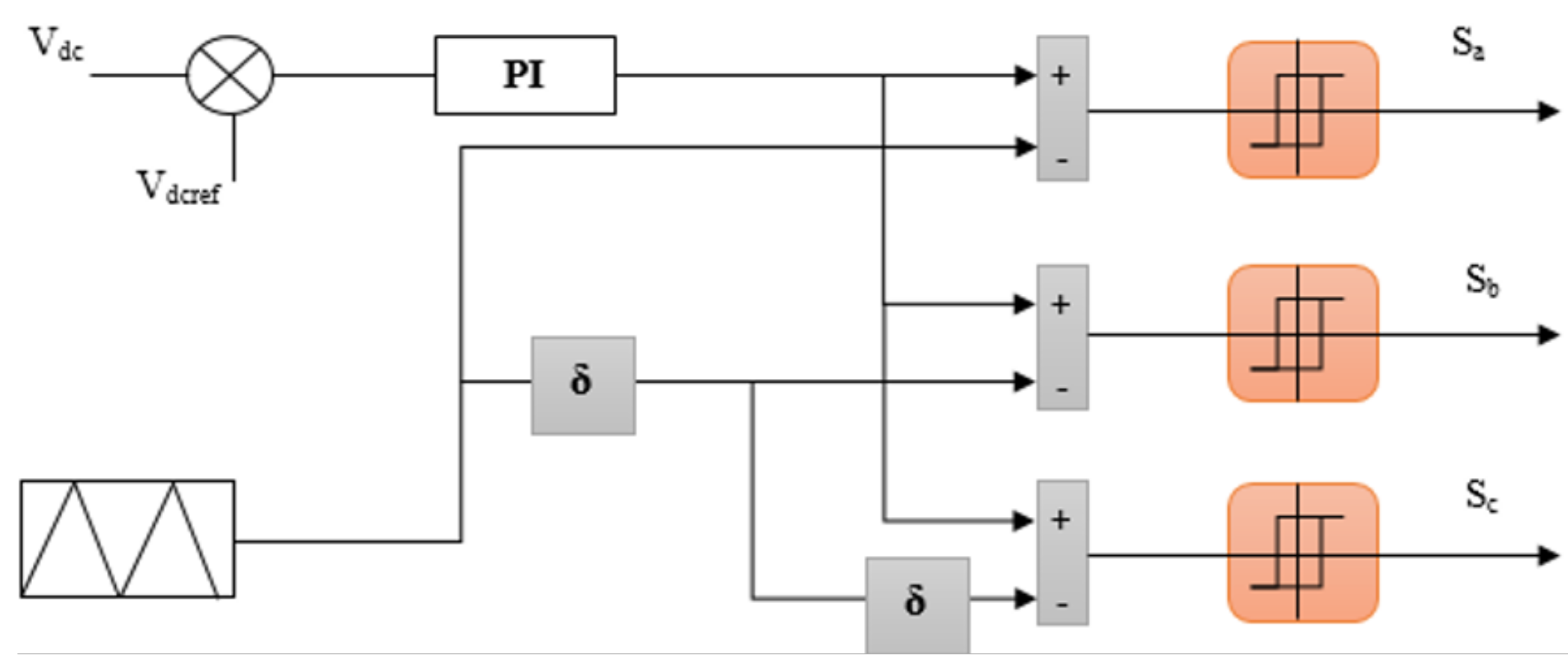
2.3. Multi-Cell Converter

The multicellular converter array is made up of a number of separate capacitor cells, each with two complementary switches [39]. Accurate voltage specifications for each cell’s terminals are necessary to ensure appropriate functioning. The eight alternative modes of operation for a three-cell converter are depicted in Figure 3. It is critical to recognize that the multicellular converter array is used in a variety of electronic systems, including inverters, voltage converters, and energy storage devices. It transforms voltage or current energy sources into usable types of energy for powering electrical equipment. The use of complementary switches for each cell increases the conversion efficiency while decreasing energy loss. Furthermore, precise voltage specifications for each cell’s terminals are required to ensure system stability and reliability.
The equation for the three-cell converter system is as follows:
I C k = ( S k + 1 S k ) I l o a d
I C k = C k d V C k d t
by combining the two previous equations, we will have:
d V C k = S k + 1 S k C k I l o a d
The voltage equations for the two floating capacitors in the converter are represented by the following differential equations:
d V C 1 d t = S 2 S 1 C 1 I l o a d d V C 2 d t = S 3 S 2 C 2 I l o a d
Based on the mesh theorem, the voltage V l o a d is determined by the sum of the voltages at the interrupt terminals:
V l o a d = k = 0 p ( V C k V C k 1 ) S k
With V C 0 = 0 V and V C p = E (in this case, V C p = V b u s ), V b u s is the output voltage of the boost converter powered by the solar field. The load current is represented by
d I l o a d d t = V o u t L R L I C
The variation of the load current is given by the following relationship:
d I l o a d d t = R L I C S 2 S 1 L V C 1 S 3 S 2 L V C 2 + E L S 3
The switches are controlled by pulses that are generated by the intersection between a modulating carrier signal and a triangular waveform as illustrated in Figure 4. The duty cycle is determined by the output voltage regulation algorithm of the serial multicellular converter.
The triangular signals are defined by the following equations:
f 1 ( u ) = arcsin sin 2 π f p t ϕ + π / 2 π f 2 ( u ) = arcsin sin 2 π f p t ϕ σ + π / 2 π . . . f p ( u ) = arcsin sin 2 π f p t ϕ ( p 1 ) σ + π / 2 π
The output signal’s harmonics would be reduced by a phase shift of 2 π / p .

3. MPPT-Optimized Steepest Gradient Method

The proposed MPPT method involves utilizing the first- and second-order Taylor approximations to optimize the cost function F ( X k ) in each iteration k. The first-order Taylor approximation is used to determine the gradient direction, while the second-order Taylor approximation determines the optimal step size in the gradient direction [40]. In each iteration k, the cost function is assessed, and the function’s gradient is computed. The gradient directs towards the steepest descent, and it is used to update the parameter vector X k . The updated parameter vector X k is then utilized to assess the cost function F ( X k ) in the next iteration. This process is repeated until the cost function reaches its minimum or maximum value, depending on the case.
In summary, the suggested MPPT method is an effective and efficient methodology for optimizing the power output of a solar panel by shifting the operating point to the maximum power point. The approach includes modifying the operating point iteratively using first- and second-order Taylor approximations until the maximum power point is reached.
The first-order approximation of the function F ( X k ) in the proximity of X k is
F ( X k ) + Δ F ( X k ) = F ( X k + σ k )
F ( X k + 1 ) = F ( X k ) + g T ( X k ) σ k = F ( X k ) + σ k F ( X k )
with
g k = g ( X k ) = F ( X k )
X k R n x 1 , g ( X k ) R n x 1 , σ k R n x 1
Then, the variation of the cost function ( Δ F ( X k ) ) is defined as the sum of the products of the gradients of the variables of the cost function by the corresponding normal vectors ( g i ) and the unit variation vectors ( σ i ) that define the search direction. The final formula given by Equation (24) is then obtained by calculating the dot product between the gradient vector of the cost function ( g k ) and the corresponding unit variation vector ( σ k ) multiplied by the cosine of the angle between these two vectors ( θ k ):
Δ F X k = i = 0 n g i σ i = g k σ k cos θ k
To maximize F ( X k ) , the greatest increase in F ( X k ) is achieved when
θ k = 0 σ k = g k
where σ k is the steepest descent direction.
In numerical computation, the solution does not always converge to X (the optimal value of X k . A tuning parameter α (a positive value) is required to ensure that the algorithm converges to the X solution. When maximizing F ( X k ) , this is the case:
X k + 1 = X k + α g k , α 0
Choosing the optimal α can be determined by using the second-order approximation of F ( X k + 1 ) :
F ( X k + 1 ) F ( X k ) + α g k T g k + 1 2 α 2 g k T H k g k
where
H k = 2 F ( X k )
If the Hessian of F ( X k ) is available, the α * that minimizes F ( X k ) can be calculated analytically by using the second-order approximation of F ( X k + 1 ) . By evaluating the Hessian at the current iterate, it can be used to approximate the local behavior of the function in the vicinity of X k . This approximation can be used to determine the step size α that will minimize F ( X k + 1 ) and, therefore, converge to the optimal solution X :
d F ( X k + α g k ) d α = g k T g k + α g k T H k σ k
d F ( X k + α g k ) d α = 0 α x = g k T g k g k T H k g k
Then,
X k + 1 = X k g k T g k g k T H k X k g k g k
In this particular case, the parameter X k , represented as V p v k (voltage), is a scalar value (a single parameter). The power function, represented as P p v k = F ( V r e f k ) , is a concave function that has a maximum value at the maximum power point (MPP). The first and second derivatives of this power function, represented as g k and H k , respectively, can be calculated using the expression of P p v k in terms of current and voltage values. These derivatives are essential in determining the optimal value of V p v k through the use of numerical optimization techniques, such as the Newton–Raphson method.
To better understand the proposed method, here are the steps of the complete mathematical modeling for the MPPT-optimized steepest gradient method control technique:
1.
Solar panel model:
The solar panel model can be represented by the following equivalent circuit equation:
I p v k = I p h I 0 ( e ( V p v k + I p v k R ) / ( α V t ) 1 )
where I p v k is the output current of the solar panel at point k; I p h is the current photo-generated by the solar panel; I 0 is the reverse saturation current of the diode; V p v k is the solar panel output voltage at point k; R is the load resistor connected to the solar panel; a is the voltage temperature coefficient; and V t is the thermal voltage.
The output power of the solar panel can be calculated as follows:
P p v k = V p v k I p v k
2.
Calculation of the power function: The power function can be represented by the following expression:
P p v k = F ( V r e f k ) = V r e f k I p h I 0 α V t 2 R e ( V r e f k α V t 1 )
where V r e f k is the solar panel reference voltage at point k.
3.
Calculation of the first and second derivatives of the power function: The first derivative of the power function with respect to the reference voltage can be calculated as follows:
g k = d F ( V r e f k ) d ( V r e f k ) = I p h 2 I 0 α V t R e ( V r e f k α V t 1 ) e V r e f k α V t
The second derivative of the power function with respect to the reference voltage can be calculated as follows:
H k = d 2 F ( V r e f k ) d ( V r e f k 2 ) = 2 I 0 α V t R [ e V r e f k α V t α V t + e ( V r e f k α V t 1 ) e V r e f k α V t ]
The algorithm of the MPPT-optimized steepest gradient method technique can be described as follows:
  • Initialize the reference voltage V r e f k to a known value;
  • Calculate the quantities of the algorithm.

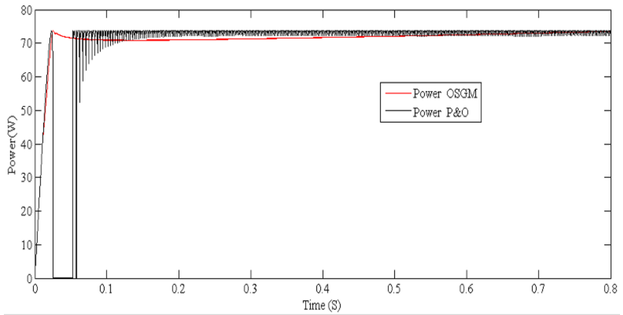
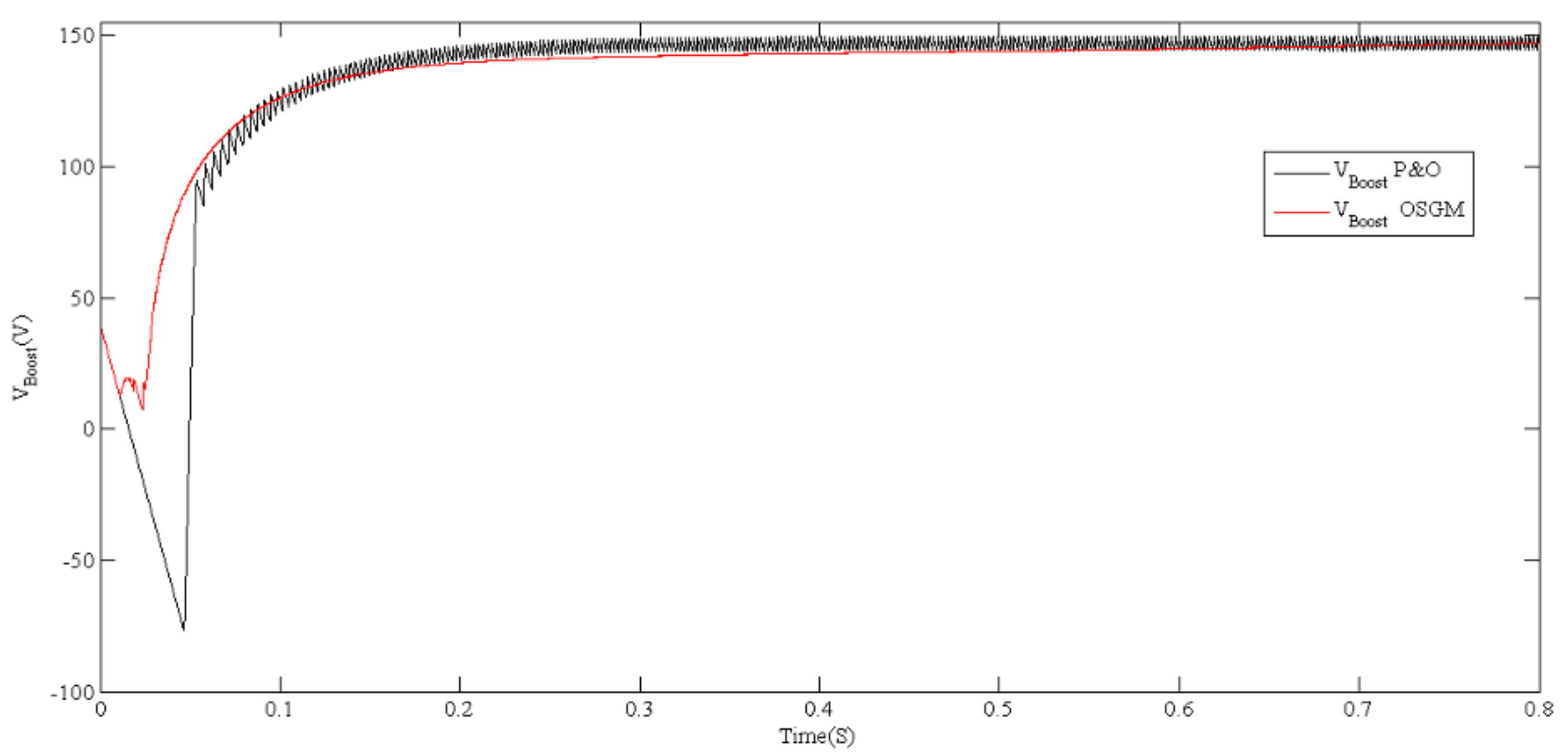
4. Results and Discussion

The simulation procedure entails modeling the system with MATLAB software tools and performing simulations to evaluate the performance of the suggested control mechanism and structure. The MPPT OSGM, an optimization technique used to maximize the power output of a photovoltaic (PV) system, is the focus of the first half of the simulation. Three tests are carried out to validate the efficiency and effectiveness of the proposed control technique and structure.
The global system parameters are summarized in Table 2 as follows.

4.1. Test 1

One of the tests conducted is Test 1, where the system is subjected to constant lighting conditions of G = 1000 W/m 2 .
Apart from the previously mentioned results, it is worth noting that the OSGM technique also achieved a higher efficiency rate when compared to the P&O method. The higher output power and fewer oscillations produced with the OSGM technique demonstrate this. Furthermore, the OSGM method is well known for its robustness and adaptability to changing environmental conditions, which is an important factor to consider when choosing an MPPT algorithm for a solar power system. Overall, the simulation results presented in Figure 5 provide clear evidence of the advantages of utilizing the OSGM method over the P&O method in terms of performance and efficiency.
The OSGM approach not only improves response time and signal quality, but it also improves the system’s overall efficiency and stability. It tracks the maximum power point precisely and quickly, resulting in increased power production from the solar system. Reduced chattering ensures system stability and reduces the risk of system failure. Furthermore, the OSGM method is a more robust choice for MPPT control in solar systems due to its adaptability to changing environmental conditions and a wider range of operating conditions. The results presented in Figure 6 confirm the superiority of the OSGM method over the traditional P&O control method.
The OSGM control approach, in addition to its capacity to eliminate disturbances, provides a more steady and constant charging current, which is critical for assuring the appropriate working and lifetime of the battery or load being charged. This is owing to its capacity to identify the maximum power point precisely and promptly, resulting in a higher power output from the solar system and effective charging of the load. Furthermore, the OSGM method is a more robust choice for MPPT control in solar systems due to its adaptability to changing environmental conditions and ability to handle a wider range of operating conditions. Overall, the results presented in Figure 7 further highlight the benefits of using the OSGM method over the traditional P&O technique for charging applications.
It is important to note that the OSGM-MPPT method also exhibits better steady-state performance as evidenced by the smaller V c 1 and V c 2 voltage oscillations when compared to the P&O method. This is a significant advantage, as it reduces the risk of converter failures and increases the overall lifespan of the system. Overall, the findings in Figure 8 underscore the superiority of the OSGM-MPPT method over the P&O method in terms of performance and efficiency in solar systems.

4.2. Test 2

The second test evaluates the OSGM method’s adaptability and effectiveness in MPPT control for solar systems by changing the lighting conditions from 600 to 1000 W/m2.
The simulation results in Figure 9 illustrate the superiority of the OSGM algorithm over the conventional P&O MPPT control method in terms of power value and stability during a test where the irradiance is varied from 600 W/m2 to G = 1000 W/m2. The output power tracked by the OSGM algorithm reaches the highest value with minimal oscillations, highlighting its capability to optimize power output in a photovoltaic system. These results are consistent with the anticipated outcomes and demonstrate the effectiveness of the proposed OSGM algorithm.
The results of the simulation in Figure 10 are clear in their demonstration of the superiority of the OSGM method over the P&O method when there is a change in the irradiance from 600 W/m2 to G = 1000 W/m2. The figure highlights the better energy quality and stability of the output voltage produced by the proposed boost method as compared to that of the P&O control.
The OSGM control method also provides a more stable charging current during a change in irradiance from 600 W/m2 to G = 1000 W/m2 as shown in Figure 11. This is important for ensuring the proper functioning and longevity of the battery or load being charged.
Figure 12 illustrates that the OSGM-MPPT method has superior performance compared to the P&O method, with smaller V c 1 and V c 2 voltage oscillations, even under changing irradiance conditions.

4.3. Test 3

Two tests for variable climatic conditions were added to assess the robustness of the proposed structure. The variations were made on the TFT site in Illizi in Algeria as part of the national research project “Design of a Cathodic Protection System with Photovoltaic Panels”. In the first case, the temperature is set at a value of 298 K, while the illumination is varied according to Figure 13.
Three cases of illumination variation are shown in Figure 13, including the most critical case “month of December”, the annual average of illumination in the TFT zone in Illizi, Algeria, and the last most favorable case.
The power and stability during the test where the site’s actual irradiance was used are illustrated by the simulation results in Figure 14. The proposed structure achieved the highest output power with minimal oscillations, demonstrating its ability to optimize the output power in a photovoltaic system and reduce loss due to switching effects.
The results of the simulation of Figure 15 are clear in their demonstration during a change of illumination in the real case. The figure highlights the better power quality and the stability of the output voltage produced by the proposed boosting method.
Better transient performance of the structure is demonstrated by the smaller Vc1 and Vc2 voltage oscillations, even during changes in illuminance as shown in Figure 16. This is a notable advantage, as it lowers the likelihood of converter failures and extends the overall lifespan of the system.
In the second case, the illumination is fixed at a value of W/m2, while the temperature is varied according to Figure 17.
Three cases of temperature variation are shown in Figure 17, including the most critical case “month of August”, the annual average of illumination in the TFT zone in Illizi, Algeria, and the last most favorable case.
Figure 18, Figure 19 and Figure 20 show the results of the proposed system during temperature variations in the Saharan environment: the output power, the boost voltage, and the floating capacitors’ voltages, respectively.
The MPPT (maximum power point tracking) control is crucial for optimizing the energy production of solar panels. It regulates the voltage and current output of the panel to maximize the supplied electrical power. However, the temperature of the photovoltaic panel can influence the performance of the MPPT control.
Indeed, an increase in the panel temperature leads to a decrease in the output voltage, which can impact energy production. This is explained by the effect of temperature on the electrical characteristics of solar cells.
However, the proposed structure for the MPPT control seems to be effective, as it does not generate energy losses due to switching, even during temperature variations. Thus, the cathodic protection system applied in Saharan areas can operate at lower temperatures without any negative effects on the performance of the MPPT control.

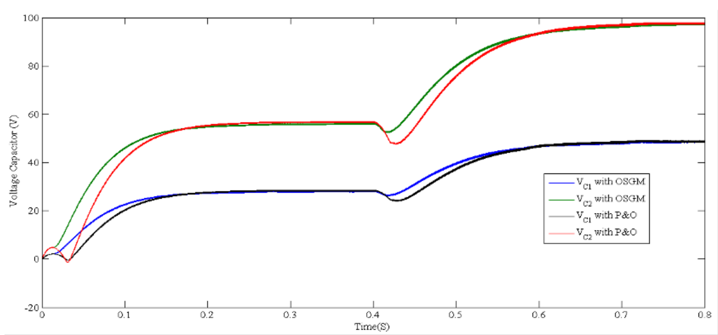
4.4. Comparative Study

The study conducted a comparative analysis of two techniques proposed by [41,42], with respect to the technique investigated in this work. The comparison criteria included P m p p (watts), current (A), V m p p (volts), time response (seconds), and the larger oscillations. The results of the comparison are presented in Table 3. The suggested approach outperformed the other two strategies in terms of response time and oscillations around the highest power point, according to the data. This performance enhancement enables the series multicellular converter to have a more steady voltage with less disturbance. These findings imply that the suggested approach is a superior choice for systems requiring higher levels of stability and efficiency. Further research can be conducted to investigate the technique’s applicability in other systems and to optimize its performance in specific applications.

5. Conclusions

The results of the simulation studies clearly demonstrate the superiority of the OSGM-MPPT method over the conventional P&O method. The OSGM method provides higher output power, more stability, better efficiency, and improved steady-state performance compared to the P&O method. It is also more resilient and flexible to changing climatic circumstances, which is critical for maintaining the solar system’s correct operation. These advantages make the OSGM-MPPT approach a viable option for MPPT control in solar energy systems. Future research might concentrate on increasing the performance of the OSGM-MPPT approach by the incorporation of additional algorithms and control strategies. Furthermore, implementing the OSGM-MPPT method in real-world solar systems and evaluating its performance under different environmental conditions would provide valuable insights for further improving the method. Simulation study, experimental analysis, and investigating the application of the OSGM-MPPT method in other renewable energy systems, such as wind or hydro-power systems, may open up new avenues for improving the efficiency and performance of these systems, which are considered future directions.

Author Contributions

Conceptualization, A.F., A.T.A. and I.A.H.; Methodology, A.F., A.T.A., I.A.H., M.L.H., K.A., H.D. and N.A.K.; Software, A.F., M.L.H., K.A., H.D., K.A. and N.A.K.; Validation, A.T.A., I.A.H., M.L.H., K.A., H.D. and N.A.K.; Formal analysis, A.F., A.T.A., I.A.H., M.L.H., K.A., H.D. and N.A.K.; Investigation, A.T.A., I.A.H., H.D., M.L.H. and N.A.K.; Resources, A.F., I.A.H., M.L.H., K.A., H.D. and N.A.K.; Data curation, M.L.H., K.A. and H.D.; Writing—original draft, A.F., A.T.A. and H.D.; Writing—review&editing, A.F., A.T.A., I.A.H., M.L.H., K.A. and N.A.K.; Visualization, A.F., A.T.A., I.A.H. and N.A.K.; Funding acquisition, I.A.H. All authors have read and agreed to the published version of the manuscript.

Funding

This research was funded by the Norwegian University of Science and Technology.

Data Availability Statement

Not applicable.

Acknowledgments

The authors would like to acknowledge the support of the Norwegian University of Science and Technology for paying the Article Processing Charges (APC) of this publication. The authors would like to thank Prince Sultan University, Riyadh, Saudi Arabia for their support. Special acknowledgement to Automated Systems & Soft Computing Lab (ASSCL), Prince Sultan University, Riyadh, Saudi Arabia. In addition, the authors wish to acknowledge the editor and anonymous reviewers for their insightful comments, which have improved the quality of this publication.

Conflicts of Interest

The authors declare that there is no conflict of interest.

References

  1. Meghni, B.; Dib, D.; Azar, A.T.; Ghoudelbourk, S.; Saadoun, A. Robust Adaptive Supervisory Fractional Order Controller for Optimal Energy Management in Wind Turbine with Battery Storage. In Studies in Computational Intelligence; Springer: Cham, Switzerland, 2017; Volume 688, pp. 165–202. [Google Scholar]
  2. Meghni, B.; Dib, D.; Azar, A.T.; Saadoun, A. Effective supervisory controller to extend optimal energy management in hybrid wind turbine under energy and reliability constraints. Int. J. Dyn. Control 2018, 6, 369–383. [Google Scholar] [CrossRef]
  3. Gorripotu, T.S.; Samalla, H.; Jagan Mohana Rao, C.; Azar, A.T.; Pelusi, D. TLBO Algorithm Optimized Fractional-Order PID Controller for AGC of Interconnected Power System. Adv. Intell. Syst. Comput. 2019, 758, 847–855. [Google Scholar]
  4. Lior, N. Sustainable energy development: The present (2009) situation and possible paths to the future. Energy 2010, 35, 39763994. [Google Scholar] [CrossRef]
  5. Antonopoulos, I.; Robu, V.; Couraud, B. Artificial intelligence and machine learning approaches to energy demand-side response: A systematic review. Renew. Sustain. Energy Rev. 2020, 130, 109899. [Google Scholar] [CrossRef]
  6. Bharany, S.; Sharma, S.; Khalaf, O.I.; Abdulsahib, G.M.; Al Humaimeedy, A.S.; Aldhyani, T.H.H.; Maashi, M.; Alkahtani, H. A Systematic Survey on Energy-Efficient Techniques in Sustainable Cloud Computing. Sustainability 2022, 14, 6256. [Google Scholar] [CrossRef]
  7. Liming, H.; Haque, E.; Barg, S. Public policy discourse, planning and measures toward sustainable energy strategies in Canada. Renew. Sustain. Energy Rev. 2008, 12, 91115. [Google Scholar] [CrossRef]
  8. Mahi, M.; Ismail, I.; Phoong, S.W. Mapping trends and knowledge structure of energy efficiency research: What we know and where we are going. Environ. Sci. Pollut. Res. 2021, 28, 35327–35345. [Google Scholar] [CrossRef]
  9. Fan, S.; Wang, Y.; Cao, S. A novel method for analyzing the effect of dust accumulation on energy efficiency loss in photovoltaic (PV) system. Energy 2021, 234, 121112. [Google Scholar] [CrossRef]
  10. Ridha, H.M.; Gomes, C.; Hizam, H. Multi-objective optimization and multi-criteria decision-making methods for optimal design of standalone photovoltaic system: A comprehensive review. Renew. Sustain. Energy Rev. 2021, 135, 110202. [Google Scholar] [CrossRef]
  11. Nassef, A.M.; Houssein, E.H.; Helmy, B.E. Modified honey badger algorithm based global MPPT for triple-junction solar photovoltaic system under partial shading condition and global optimization. Energy 2021, 254, 124363. [Google Scholar] [CrossRef]
  12. El Hammoumi, A.; Chtita, S.; Motahhir, S. Solar PV energy: From material to use, and the most commonly used techniques to maximize the power output of PV systems: A focus on solar trackers and floating solar panels. Energy Rep. 2022, 8, 11992–12010. [Google Scholar] [CrossRef]
  13. Zhu, F.; Zhong, P.; Sun, Y. A coordinated optimization framework for long-term complementary operation of a large-scale hydro-photovoltaic hybrid system: Nonlinear modeling, multi-objective optimization and robust decision-making. Energy Convers. Manag. 2020, 226, 113543. [Google Scholar] [CrossRef]
  14. Bhukya, L.; Kedika, N.R.; Salkuti, S.R. Enhanced Maximum Power Point Techniques for Solar Photovoltaic System under Uniform Insolation and Partial Shading Conditions: A Review. Algorithms 2022, 15, 365. [Google Scholar] [CrossRef]
  15. Aguila-Leon, J.; Vargas-Salgado, C.; CHIÑAS-PALACIOS, C. Solar photovoltaic Maximum Power Point Tracking controller optimization using Grey Wolf Optimizer: A performance comparison between bio-inspired and traditional algorithms. Expert Syst. Appl. 2023, 211, 118700. [Google Scholar] [CrossRef]
  16. Ndiaye, A.; Tankari, M.A.; Lefebvre, G. Adaptive neuro-fuzzy inference system application for the identification of a photovoltaic system and the forecasting of its maximum power point. In Proceedings of the 7th International Conference on Renewable Energy Research and Applications (ICRERA), Paris, France, 14–17 October 2018; pp. 1061–1067. [Google Scholar]
  17. Kuate, N.; Pascal, N.; Kenmeugne, B. Artificial neural network (ANN) and adaptive neuro-fuzzy inference system (ANFIS): Application for a photovoltaic system under unstable environmental conditions. Int. J. Energy Environ. Eng. 2022, 13, 821–829. [Google Scholar] [CrossRef]
  18. Belhachat, F.; Larbes, C. Global maximum power point tracking based on ANFIS approach for PV array configurations under partial shading conditions. Renew. Sustain. Energy Rev. 2017, 77, 875–889. [Google Scholar] [CrossRef]
  19. Walia, N.; Singh, H.; Sharma, A. ANFIS: Adaptive neuro-fuzzy inference system—A survey. Int. J. Comput. Appl. 2015, 123, 32–38. [Google Scholar] [CrossRef]
  20. Bataineh, K.; Eid, N. A Hybrid Maximum Power Point Tracking Method for Photovoltaic Systems for Dynamic Weather Conditions. Resources 2018, 7, 68. [Google Scholar] [CrossRef] [Green Version]
  21. Alabedin, A.Z.; El-Saadany, E.F.; Salama, M. Maximum power point tracking for Photovoltaic systems using fuzzy logic and artificial neural networks. In Proceedings of the IEEE Power and Energy Society General Meeting, Detroit, MI, USA, 24–28 July 2011; pp. 1–9. [Google Scholar]
  22. Kulaksiz, A. ANFIS-based estimation of PV module equivalent parameters: Application to a stand-alone PV system with MPPT controller. Turk. J. Electr. Eng. Comput. Sci. 2013, 21, 2127–2140. [Google Scholar] [CrossRef]
  23. Ndiaye, A.; Faye, M. Experimental Validation of PSO and Neuro-Fuzzy Soft-Computing Methods for Power Optimization of PV installations. In Proceedings of the 8th International Conference on Smart Grid (icSmartGrid), Paris, France, 17–19 June 2020; pp. 189–197. [Google Scholar]
  24. Manoharan, P.; Subramaniam, U.; Babu, T.S.; Padmanaban, S.; Holm-Nielsen, J.B.; Mitolo, M.; Ravichandran, S. Improved Perturb and Observation Maximum Power Point Tracking Technique for Solar Photovoltaic Power Generation Systems. IEEE Syst. J. 2021, 15, 3024–3035. [Google Scholar] [CrossRef]
  25. Patel, A.; Gnana Swathika, O.V.; Subramaniam, U.; Babu, T.S.; Tripathi, A.; Nag, S.; Karthick, A.; Muhibbullah, M. A Practical Approach for Predicting Power in a Small-Scale Off-Grid Photovoltaic System Using Machine Learning Algorithms. Int. J. Photoenergy 2022, 2022, 9194537. [Google Scholar] [CrossRef]
  26. Hmidet, A.; Subramaniam, U.; Elavarasan, R.M.; Raju, K.; Diaz, M.; Das, N.; Mehmood, K.; Karthick, A.; Muhibbullah, M.; Boubaker, O. Design of Efficient Off-Grid Solar Photovoltaic Water Pumping System Based on Improved Fractional Open Circuit Voltage MPPT Technique Available. Int. J. Photoenergy 2021, 2021, 4925433. [Google Scholar] [CrossRef]
  27. Inthamoussou, F.; Valenciaga, F. A fast and robust closed-loop photovoltaic MPPT approach based on sliding mode techniques. Sustain. Energy Technol. Assess. 2021, 47, 101499. [Google Scholar] [CrossRef]
  28. Eltawil, M.; Zhao, Z. MPPT techniques for photovoltaic applications. Renew. Sustain. Energy Rev. 2013, 25, 793–813. [Google Scholar] [CrossRef]
  29. Hassan, A.; Bass, O.; Masoum, M. An improved genetic algorithm based fractional open circuit voltage MPPT for solar PV systems. Energy Rep. 2023, 9, 1535–1548. [Google Scholar] [CrossRef]
  30. Sera, D.; Mathe, L.; Kerekes, T. On the perturb-and-observe and incremental conductance MPPT methods for PV systems. IEEE J. Photovolt. 2013, 3, 1070–1078. [Google Scholar] [CrossRef]
  31. Lyden, S.; Haque, E. Maximum Power Point Tracking techniques for photovoltaicsystems: A comprehensive review and comparative analysis. Renew. Sustain. Energy Rev. 2015, 52, 1504–1518. [Google Scholar] [CrossRef]
  32. Jordehi, A.R. Maximum power point tracking in photovoltaic (PV) systems: A review of different approaches. Renew. Sustain. Energy Rev. 2016, 65, 1127–1138. [Google Scholar] [CrossRef]
  33. Khan, M.J.; Mathew, L. Artificial neural network-based maximum power point trackingcontroller for real-time hybrid renewable energy system. Soft Comput. 2021, 25, 6557–6575. [Google Scholar] [CrossRef]
  34. Hai, T.; Wang, D.; Muranaka, T. An improved MPPT control-based ANFIS method to maximize power tracking of PEM fuel cell system. Sustain. Energy Technol. Assess. 2022, 54, 102629. [Google Scholar] [CrossRef]
  35. Gong, L.; Hou, G.; Huang, C. A two-stage MPPT controller for PV system based on the improved artificial bee colony and simultaneous heat transfer search algorithm. ISA Trans. 2023, 132, 428–443. [Google Scholar] [CrossRef]
  36. Rahman, M.; Islam, S. Artificial Neural Network Based Maximum Power Point Tracking of a Photovoltaic System. In Proceedings of the 3rd International Conference on Electrical, Computer &Telecommunication Engineering (ICECTE), Rajshahi, Bangladesh, 26–28 December 2019; pp. 117–120. [Google Scholar]
  37. Priyadarshi, N.; Padmanaban, S.; Mihet-Popa, L.; Blaabjerg, F.; Azam, F. Maximum Power Point Tracking for Brushless DC Motor-Driven Photovoltaic Pumping Systems Using a Hybrid ANFIS-FLOWER Pollination Optimization Algorithm. Energies 2018, 11, 1067. [Google Scholar] [CrossRef] [Green Version]
  38. Sanghavi, B.M.; Tejaswini, C.; Venkareshappa, V. DC/DC boost converter using DSP controller for fuel cell. Perspect. Commun. Embed. Syst. Signal-Process. Pices 2019, 2, 248–251. [Google Scholar]
  39. Hamida, M.L.; Denoun, H.; Fekik, A.; Benyahia, N.; Benamrouche, N. Cyclic reports modulation control strategy for a five cells inverter. In Proceedings of the International Conference on Electrical Sciences and Technologies in Maghreb (CISTEM), Algiers, Algeria, 28–31 October 2018; pp. 1–5. [Google Scholar]
  40. Amara, K.; Bakir, T.; Malek, A.; Hocine, D.; Bourennane, E.B.; Fekik, A.; Zaouia, M. An optimized steepest gradient based maximum power point tracking for PV control systems. Int. J. Electr. Eng. Inform. 2019, 11, 662–683. [Google Scholar] [CrossRef]
  41. Amara, K.; Fekik, A.; Hocine, D. Improved performance of a PV solar panel with adaptive neuro fuzzy inference system ANFIS based MPPT. In Proceedings of the 7th International Conference on Renewable Energy Research and Applications (ICRERA), Paris, France, 14–17 October 2018; pp. 1098–1101. [Google Scholar]
  42. Amara, K.; Malek, A.; Bakir, T.; Fekik, A.; Azar, A.T.; Almustafa, K.M.; Bourennane, E.B.; Hocine, D. Adaptive neuro-fuzzy inference system based maximum power point tracking for stand-alone photovoltaic system. Int. J. Model. Identif. Control 2019, 33, 311–321. [Google Scholar] [CrossRef]
Figure 1. The proposed structure.
Electronics 12 02283 g001
Figure 2. Boost structure.
Electronics 12 02283 g002
Figure 3. Three-cell converter.
Electronics 12 02283 g003
Figure 4. PWM with PI Control.
Electronics 12 02283 g004
Figure 5. PV output power.
Electronics 12 02283 g005
Figure 6. Output boost voltage.
Electronics 12 02283 g006
Figure 7. Current load.
Electronics 12 02283 g007
Figure 8. Floating voltage.
Electronics 12 02283 g008
Figure 9. PV power output.
Electronics 12 02283 g009
Figure 10. Output boost voltage.
Electronics 12 02283 g010
Figure 11. Current load.
Electronics 12 02283 g011
Figure 12. Floating voltage.
Electronics 12 02283 g012
Figure 13. Illumination variation.
Electronics 12 02283 g013
Figure 14. Power with illumination variation.
Electronics 12 02283 g014
Figure 15. Output voltage with illumination variation.
Electronics 12 02283 g015
Figure 16. Voltage capacitors with illumination variation.
Electronics 12 02283 g016
Figure 17. Temperature variation.
Electronics 12 02283 g017
Figure 18. Power with temperature variation.
Electronics 12 02283 g018
Figure 19. Output voltage with temperature variation.
Electronics 12 02283 g019
Figure 20. Floating voltage with temperature variation.
Electronics 12 02283 g020
Table 1. The main parameters of PV.
Module ParametersValues
Power at MPP: P m a x P m a x = 75 W
Open circuit voltage: V o c V o c = 21.7 V
Short current circuit: I s c I s c = 4.8 A
Voltage at MPP: V m p p V m p p = 17 V
Current at MPP: I m p p I m p p = 4.4 A
Table 2. System parameters.
ParametersValues (Unit)
Boost Capacitor2200 µF
Floating Capacitor (multicell converter)33 µF
Inductance (Multicell converter)15 mH
Inductance boost100 mH
DC Voltage reference (Multicell converter)145 V
Commutation frequency1.5 KHz
PI Gains (Multi cell voltage regulation) K p = 40; & K i = 0.001
Table 3. Comparative study.
MPPT Techniques P m p p (Watts)Current (A) V m p p (Volts)Time Response (Seconds)The Larger of OscillationsReferences
P&O72.804.6715.600.40 (Slow)Very large [42]
ANFIS74.454.4316.780.05 (Fast)Small [41]
Proposed Method74.754.4216.880.025 (very Fast)Small———
Disclaimer/Publisher’s Note: The statements, opinions and data contained in all publications are solely those of the individual author(s) and contributor(s) and not of MDPI and/or the editor(s). MDPI and/or the editor(s) disclaim responsibility for any injury to people or property resulting from any ideas, methods, instructions or products referred to in the content.

