Abstract
The distributed Goppa-coded generalized spatial modulation (DGC-GSM) scheme with the source, relay, and destination in cooperative communications is proposed, where the source and relay adopt different Goppa codes. Goppa codes have many advantages such as the flexible codeword length, excellent code construction, and easy encoding and decoding complexity. At the relay, we select portions of the source information bits for further encoding. For each selection, the destination constructs a channel code. To obtain the best code in the destination, we propose the optimal information bit selection algorithm at the relay to choose the source information. However, Goppa codes with a large block length will impose high complexity on the optimal algorithm. Thus, the locally optimized selection algorithm is further proposed. At the destination, the joint decoding algorithm is adopted to recover the source information. Our simulated results indicate that the two selection algorithms proposed achieve better performance than the random selection method. This is because the optimized algorithms can generate the code with a larger minimum distance at the destination. Moreover, the proposed DGC-GSM scheme outperforms the non-cooperative system. Moreover, the DGC-GSM scheme can obtain the approximate performance with the distributed Goppa-coded spatial modulation (DGC-SM) scheme but has a significantly reduced transmit antenna number.
1. Introduction
Multiple-input–multiple-output (MIMO) is a key technique that effectively enhances system reliability [1]. A recently developed MIMO technology, i.e., spatial modulation (SM) [2], only uses a single active transmit antenna for signal transmission in each time instant, which completely avoids inter-channel interference (ICI). The active antenna index also carries information, so the spectral efficiency is boosted. Nevertheless, SM has the limitation that the transmit antenna number is the power of two. To overcome the shortcoming in SM, the literature [3] presented the fractional bit encoded SM scheme with an arbitrary transmit antenna number allowed. However, error propagation resulted in the system. An alternative method of circumventing the constraint on the antenna number is generalized SM (GSM) [4]. In GSM, using multiple active antennas to transmit the same constellation symbol causes the system to retain the advantage of SM (i.e., avoiding the ICI) and have higher spectral efficiency than SM. Moreover, the transmit antenna number in GSM is significantly reduced over SM under an identical spectral efficiency. Moreover, in GSM, transmitting the replicas of the symbol enhances the channel reliability.
Another technology that can effectively improve the system reliability is coded cooperation (CC) (i.e., distributed channel codes) [5] with the integration of channel coding and cooperative technologies such as amplify-and-forward (AF) [6] and decode-and-forward (DF) [7]. The typical CC usually has three terminals called the source, relay, and destination, where the source and relay cooperate with each other so that a channel code is yielded in the destination. Many binary distributed channel coding schemes utilizing channel codes such as Reed–Muller codes, turbo codes, low-density parity-check codes, and polar codes have been widely studied in many studies such as [8,9,10,11]. It can be observed that the distributed channel coding scheme is able to obtain the coded cooperative diversity gains and achieve better performance than the direct non-cooperative counterpart. However, there are few reports in the literature of distributed coding systema adopting non-binary codes, especially non-binary maximum-distance separable (MDS) codes.
As special non-binary MDS codes, Reed–Solomon (RS) codes [12] have a strong ability to correct random and burst errors, which attracts attention. For example, previous research [13,14,15] designed a distributed RS coding system and investigated the system’s error performance. However, the system’s design flexibility was reduced due to the fact that RS codes over the field GF(qm) have a limited codeword length of with q being the prime and m being the positive integer. Interestingly, another class of non-binary MDS codes, i.e., generalized RS (GRS) codes [16,17,18], as the extension of RS codes, has more flexible and variable codeword lengths. Since the subcodes of the original channel codes have a minimum distance of no less than that of the original channel codes, this inspires us to apply the subfield subcodes of GRS codes in CC. Goppa codes [19], as the famous subfield subcodes of GRS codes, can obtain a significantly larger minimum distance than GRS codes. Additionally, Goppa codes possess many benefits such as the flexible codeword length, excellent code construction, and easy encoding and decoding complexity. Thus, many scholars have performed wide research on Goppa codes in many studies such as [19,20,21,22,23]. However, these studies primarily focus on the introduction of basic principles and characteristics. Thus, they do not fully use the advantages of MIMO and cooperative technologies and cannot meet the demands of highly reliable and effective communications.
In order to address the gap to achieve high reliability and effectiveness of communication, we study the integration of distributed Goppa coding (DGC) and GSM and propose the distributed Goppa-coded GSM (DGC-GSM) scheme. The high reliability and effectiveness of the DGC-GSM scheme can be achieved through the following methods: (1) The relay carries out the optimized selection of the source information bits to ensure the destination generates a code with a larger minimum distance and the destination uses a joint decoding algorithm for effective recovery of source information, which improves the reliability of the DGC system. (2) At the source and relay, the introduction of GSM improves the effectiveness of the DGC-GSM scheme while enhancing reliability. The key contributions are listed below:
- The DGC-GSM scheme utilizing information selection in the relay is proposed, where the source and relay use different Goppa codes. The encoded codeword at the source is sent to the relay and destination. The relay first decodes the source signal to obtain the estimated source message bits and then chooses partial bits from the decoded message bits to encode them. By combining the codewords transmitted from the source and relay, a channel code is constructed in the destination under the assumption of the error-free decoding in the relay. In the relay, any decoding strategy will result in erroneous decoding and therefore cannot ensure error-free transmission.
- Through the relay’s proper selection of partial bits from the decoded source message bits, a channel code with a larger minimum distance can be constructed at the destination. To construct the best code in the destination, the optimal information bit selection algorithm in the relay is proposed to effectively choose the source information bits.
- Since the optimal algorithm considers all selection methods and source information sequences, it has relatively high computational complexity for the case of Goppa codes with large block lengths. To reduce the complexity, the locally optimized information bit selection algorithm considering partial selection and source information sequences is proposed.
- To effectively recover the source information, we adopt the joint decoding algorithm in the destination to decode the signals from the source-to-destination and relay-to-destination wireless channels.
The reminder of this manuscript is as follows: Section 2 introduces the related work. The DGC-GSM scheme with the information selection in the relay is proposed in Section 3. Section 4 introduces two optimized information bit selection algorithms. Section 5 describes the joint decoding algorithm. Section 6 outlines the performance analysis for the proposed system. The simulated results are discussed in Section 7. Finally, we conclude this paper.
Notations: Bold italic capital and lowercase letters represent the matrix and vector, respectively. and represent the inverse and transpose operations, respectively. We use and to denote the largest value no greater than x and the smallest value no less than x, respectively. represents the complex domain. is the binomial coefficient. Additionally, is the complex distribution with x mean and y variance. |a|b| denotes the series connection of a and b. denotes the complex conjugate and represents the real part of a complex value.
2. Related Work
In [13], the authors studied the error performance of an RS-coded cooperative system and presented a novel approach to deal with the selection of a cooperative level between two users. Another study in the literature [14] designed a coded cooperative scheme on the basis of RS codes and confirmed the performance superiority of the designed system over the existing punctured convolutional-coded cooperative scheme. Nevertheless, they did not fully utilize the advantages of cooperative diversity and MIMO technology. Thus, Zhao et al. [24] presented a novel distributed RS coding scheme with the MIMO technique, i.e., SM. Unfortunately, the limited codeword length of RS codes affects the system’s design flexibility of the RS-coded cooperative schemes.
Interestingly, as the extension of RS codes, GRS codes can circumvent the limitation of the codeword length. A detailed introduction to the basic knowledge of GRS codes was provided in [16,17,18]. Due to the fact that the subfield subcodes of the original codes can further enhance the minimum distance of the original codes, more and more scholars are focusing on the study of the subfield subcodes of GRS codes. Since Goppa codes as the subfield subcodes of GRS codes have a flexible codeword length and excellent construction, they have been widely investigated. For example, in [19], the dimensions and structure of the square of dual Goppa codes was studied, and a corresponding rigorous upper bound was also provided. In [20], the authors discussed cyclic extended Goppa codes with double-error-correcting capability. The authors in [21] used the concept of dihedral automorphism groups and constructed expurgated and extended Goppa codes. The literature [23] discussed the completely decomposed cumulative Goppa codes and the enhanced bound of the minimum distance. These studies on Goppa codes did not incorporate MIMO-based cooperative technology and therefore cannot meet the high demands for effective and reliable communication services. Motivated by this, we apply Goppa codes to the cooperative system based on MIMO and propose the DGC-GSM system.
Different from the existing strategies, the proposed system has made much progress: (1) Goppa codes are first integrated into the MIMO-based cooperative communication system to effectively improve the reliability and effectiveness. (2) At the relay, we suitably select the partial message from the estimated source information and re-encode the selected information, which causes the code generated in the destination to possess a larger minimum distance. (3) At the destination, we perform excellent joint decoding on the received source-to-destination and relay-to-destination signals, which contributes to the correct decoding. Table 1 clearly compares the proposed work with the state-of-the-art literature.

Table 1.
Comparison between the proposed work and the state-of-the-art literature.
3. GSM-Based Goppa-Coded Cooperative System Design
This section discusses the DGC-GSM scheme that combines the DGC and GSM, where the relay adopts the idea of information selection.
3.1. Fundamentals of Goppa Codes
We assume that G(z) is a degree-r Goppa polynomial and its coefficients belong to the field , and with for , where and q are the positive integer and prime number, respectively. For the two arbitrary vectors and with and , the rational function is expressed as follows [20]:
The set of all the vectors satisfying the condition constructs the Goppa code with the codeword length n. has the parity-check matrix given by [21]:
Then, we obtain the matrix over GF(q) by converting each element in Equation (2) into an m-dimensional column vector in GF(q). Through the linear transformation of , the systematic parity-check matrix is obtained. Then, we acquire the systematic generator matrix G based on .
Example 1.
Let the field with being the root of over GF(2). Let and . By using Equation (2), the parity-check matrix H is written as:
By converting each element in Equation (3) into a three-dimensional column vector, we obtain the following matrix :
Then, we obtain the systematic form of , where is shown as follows:
Based on Equation (5), the generator matrix G is directly expressed as:
3.2. System Model in Cooperative Scenarios
The system diagram of the proposed DGC-GSM is depicted in Figure 1. NT, NT, and NR antennas are deployed in the source S, relay R, and destination D, respectively. Realizing an overall system transmission needs two time slots.
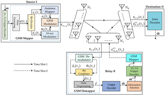
Figure 1.
System model of the DGC-GSM scheme.
In time slot-1, the information bit sequence m of length k1 is encoded into the systematic codeword bit sequence of length using the Goppa encoder, where is the parity-check part. Through the GSM mapper, the yielded codeword bit sequence c is mapped to the GSM transmission vector. Specifically, the data grouping first accepts c and partitions it into multiple short sequences with the same length , where is the time instant with being the added zero bits in the end of to make be an integer, is the activated transmit antenna number and M is the modulation order. The bit divider splits into two parts, where the first bits and the remaining bits separately constitute the first and second parts. Through the antenna mapper and M-ary modulator, is mapped to an active transmit antenna combination (TAC) from the TACs used and is mapped to a modulated symbol from the total M modulated symbols, where is the j-th active transmit antenna index. Through the GSM modulator, the modulated symbol is transmitted via the TAC , and we obtain the GSM transmission vector :
The vector is separately sent to the R and D through slow Rayleigh fading channels and to yield the signal vectors and :
where each element of is independent and obeys the distribution . with being the column of . is the noise vector with each element having the independent and identical distribution . , , and have similar definitions to , , and , respectively.
In time slot-2, the GSM demodulator first performs demodulation for by utilizing maximum-likelihood detection (MLD) to obtain the estimate of and , i.e., and . Through the bit combiner (the execution process of the bit combiner is in contrast to the execution process of the bit divider), we obtain the estimated sequence of . After the data ungrouping, the estimate of c is generated. Next, the Goppa decoder is used for decoding to obtain the estimated of m by using the Euclidean decoding algorithm [22]. The k2 (k2 < k1) information bits are selected from and the Goppa encoder encodes into the systematic codeword bit sequence of length , where is the selection order and is the parity-check part. Because the proper information selection at R plays a key role in improving the whole system performance, it is extremely necessary to design the optimized information bit selection algorithm. The details will be introduced in Section 4. After the sequence is inserted into the GSM mapper, we obtain the transmission vector :
where is defined as . The modulated symbol is transmitted via the TAC with . Through the slow Rayleigh fading channel , the vector is sent to the D, which obtains the signal vector :
where , , and are defined as , and , respectively. Eventually, the joint decoder performs joint decoding for the signal vectors and during two respective time slots to obtain the estimated source information bits. The detailed process of recovering the source message bits is discussed in Section 5.
Example 2.
Let be the length Goppa codeword at the S. Furthermore, , , and 32-QAM (M = 32) are assumed. Thus, and with . Then, we have , and , where the sequence is mapped to the active TAC and the sequence is mapped to the modulated symbol . The GSM transmission vector has the following expression form:
We assume that , , , and have the mathematical expressions written as follows:
Then, we obtain:
Furthermore, we assume that the Goppa codeword with a length of is at the R. The GSM transmission vector can be directly written as:
where and . We assume that and have the following expressions:
Then, we obtain:
4. Design Algorithms of Optimized Selection at the Relay
At S and R, the Goppa codes and are separately used with being the minimum distance. The R selects bits from the estimated source message sequence of length for further encoding by the use of the Goppa code , and there are a total of selections, where . Each selection order i corresponds to a -dimensional vector , and the set of all L selection patterns is expressed as:
where refers to the position of the selected element in . Under the correct decoding (i.e., ) at the R, the i-th selection pattern makes the D generate a channel code expressed as:
where and are separately the Goppa codes at the S and R with being the minimum distance. It is worth mentioning that the condition is assumed in this paper. To obtain the code with a better codeword weight distribution, we propose two effective information selection algorithms to determine the corresponding optimized selection pattern and then perform proper information selection by the determined optimized pattern.
4.1. Optimal-Based Selection Design Algorithm
4.1.1. Design Steps
The proposed optimal information bit selection algorithm in this section aims to find a selection pattern that produces the best codeword weight distribution at the D among all L selection patterns. During the procedure of the search, all information sequences at the S are taken into account. Algorithm 1 explicitly shows the search process of the optimal pattern .
| Algorithm 1: Optimal Selection Algorithm |
| Input: , , , , L, Output: The optimal selection pattern Step 1: Determine all source information sequences. Step 2: Determine the sets I and at the R. Step 3: For each and , we get all the codeword sets resulted by source information sequences, and find out the minimum codeword weight . Then, we determine . Step 4: Obtain and . Step 5: For , we end the algorithm and the only element in is determined as the optimal selection pattern , i.e., . Step 6: For ,
|
4.1.2. Complexity Analysis
Here, we analyze the encoding complexity of the optimal algorithm under addition and multiplication operations. In the S, addition operations and multiplication operations are required to encode one message sequence of length k1. Thus, completing the encoding of all information sequences in the S requires the overall computational complexity denoted as:
Similarly, the corresponding complexity of encoding our obtained information bit sequences in the R is when considering one selection pattern. We allow the number of considered selection patterns to be in determining the number of , ) in the D. Provided that is obtained when determining the number of (), the overall complexity at the R is:
Therefore, the total computational complexity of the optimal algorithm is:
4.2. Locally Optimized-Based Selection Design Algorithm
4.2.1. Design Steps
For Goppa codes with large block lengths, the optimal algorithm has relatively high complexity when considering all source information sequences and all L selection patterns. To reduce the complexity of the best algorithm, the locally optimized information bit selection algorithm is presented to determine the optimized one from partial selection patterns of L selection patterns, during which partial source information sequences of source information sequences are considered. The search process of the locally optimized pattern is shown in Algorithm 2.


| Algorithm 2: Locally Optimized Selection Algorithm |
| Input: , , , Output: The locally optimized selection pattern Step 1: At the S, we determine K source information bit sequences m. Because the source information sequences m yielding codeword weight wt(c) = q () can be selected from those sequences m of weight 1 , this implies the corresponding message sequences m possess, at most, q bits 1, i.e., the realistic number of bits 1 is 1 . The generation process of K source message sequences is as follows:
Step 4: Other steps are similar to steps 3–6 of Algorithm 1. Finally, we obtain . |
Figure 2.
Illustrated diagram of k1 source information bit positions (a) more information bit positions are in the 1st part (b) more information bit positions are in the 2nd part.
Figure 2.
Illustrated diagram of k1 source information bit positions (a) more information bit positions are in the 1st part (b) more information bit positions are in the 2nd part.
4.2.2. Complexity Analysis
Now, we analyze the complexity of the locally optimized algorithm regarding addition and multiplication operations. Since K information sequences are considered in the S, the total encoding complexity of the S is:
In the R, the complexity of encoding K selected information bits for one selection pattern is . When determining the number of , ) in the D, selection patterns are considered, where is similar to in Algorithm 1. Suppose that we can obtain the optimized pattern when finding out the number of (), Then, the total complexity at the R is computed as:
Thus, the locally optimized algorithm has the overall computational complexity denoted as follows:
4.3. Design Examples and Computation of Complexity of the Two Algorithms
4.3.1. Design Examples
To facilitate the understanding for the proposed two algorithms, we give the following examples.
Example 3.
At the S and R, we consider the Goppa codes and , respectively. Table 2 lists the related parameters and over with being the root of over GF(2). By using the optimal algorithm, the process of determining is as follows:
Step 1: Determine all source information sequences.
Step 2: Determine the set and the set with 70 selection patterns, where is denoted as follows:
Step 3: For each and , we obtain all codeword sets resulting in source information sequences, and determine .
Step 4: Obtain and .
Step 5: Because of , we end the algorithm and finally obtain .
Table 2.
Parameters and corresponding to the Goppa codes at the S and R.
Table 2.
Parameters and corresponding to the Goppa codes at the S and R.
| Goppa Codes | ||
|---|---|---|
Example 4.
We adopt the coding parameters in Example 3. The process of determining by using the locally optimized algorithm is as follows:
Step 1: Determine K source information bit sequences at the S:
- (a)
- Divide the bit positions of the information sequence m into two parts based on Figure 2.
- (b)
- For each wt(c) = q (5), we determine the positions of (1) bits 1 of m: ① In Figure 2a, we randomly choose ()) positions in the 1st part to put bits 1, and fixedly choose positions to put bits 1 in the 2nd part, which yields cases. ② In Figure 2b, cases are also yielded by randomly choosing positions in the 2nd part to put bits 1, and fixedly choosing positions in the 1st part to put bits 1.
- (c)
- By considering all cases for each wt(c) = q, we obtain K = 189 < source information bit sequences.
Step 2: Determine Q selection patterns:
- (a)
- Choose bit positions from the bit positions: ① In Figure 2a, (3) bit positions are randomly chosen from the 1st part, and bit positions are fixedly chosen from the 2nd part, which generates cases. ② In Figure 2b, cases are also generated by randomly choosing bit positions from the 2nd part and fixedly choosing bit positions from the 1st part.
- (b)
- By considering all cases, we obtain Q = 24 70 selection patterns .
Step 3: Determine the set and the set , where is denoted as:
Step 4: For each and , we obtain all codeword sets yielded by 189 source message sequences and determine .
Step 5: Obtain and .
Step 6: Because of , we end the algorithm, and the locally optimized pattern is
4.3.2. Computation of Complexity
We can compute the complexities of the proposed algorithms using Equations (27) and (30). In Example 3, the complexity of the optimal algorithm is mathematically computed as:
In Example 4, the complexity of the locally optimized algorithm is computed as:
It can be found that the calculation operations of the locally optimized algorithm have a 73% complexity reduction compared with the optimal algorithm. Thus, this phenomenon reveals the low-complexity characteristic of the proposed locally optimized algorithm.
5. Joint Decoding in the Destination
In our proposed DGC-GSM system, the effective joint decoding helps to obtain the correct source information bits. Since the Goppa code in the R has a larger minimum distance than that in the S (i.e., ) as mentioned in Section 4, it is beneficial to enhance the entire performance of the cooperative system by using the reliable relay information bits to replace the selected source information bits. Algorithm 3 illustrates the detailed decoding process of the joint decoding algorithm.
| Algorithm 3: Joint Decoding Algorithm |
| Input: The signal vectors and Output: The estimated source information sequence Step 1: The D uses the GSM demapper using MLD to separately demodulate the signal vectors and and obtains the estimated codeword bit sequences and of c and , respectively. Step 2: By using the Euclidean decoding algorithm, the Goppa decoder decodes to obtain the estimate of relay information sequence with length. Step 3: We utilize the estimated sequence to replace those selected bits in the demodulated codeword sequence and the update of is yielded. Step 4: Finally, we adopt the Goppa decoder to perform decoding for to generate the estimated source information . |
6. Performance Analysis
This section analyzes the theoretical performance of the proposed DGC-GSM system. In the source-to-destination (S-D) and relay-to-destination (R-D) links, the bit error rate (BER) performances are separately represented as:
where t is the error correction capability of the code generated in the D with being the minimum distance. Additionally, and are the BER performances of GSM and are expressed as:
In Equation (37), is the number of error bits between the GSM transmission vectors and with and separately being the modulated symbol set and active TAC set, where . is the regularised incomplete beta function [25]. (dB) is the signal-to-noise ratio (SNR) of the S-D link and , where is the number of different bits between and . In Equation (38), , , and are defined as , , and , respectively. Under the case of the noiseless S-R link, the average BER of the cooperative system is denoted as:
In the case of the noisy S-R link, the theoretical BER can also be calculated according to Equation (39). In this case, is viewed as the equivalent SNR based on the quality of the S-R link, where the improvement and deterioration of the S-R link correspond to the increase and decrease in the equivalent SNR.
7. Simulations and Discussions
In this section, we discuss the BER performance of the proposed DGC-GSM scheme under various simulation conditions such as different information bit selection algorithms and different transmit and receive antenna numbers. The proposed coded cooperative scheme is also compared with the non-cooperative system, the current strategies, and the distributed Goppa-coded SM (DGC-SM) scheme to exhibit its advantages. We use two different distributed Goppa codes as illustrated in Table 3, where the set and the Goppa polynomial G(z) are used to construct the Goppa codes. In and G(z), the parameters and are the roots of polynomials and over GF(2), respectively. Moreover, Table 3 lists the optimal selection pattern and the locally optimized selection pattern .
Table 3.
Parameters and selection patterns corresponding to different distributed Goppa codes.
The SNRs of the S-D, S-R and R-D links are denoted as , , and , respectively. When , the S-R link is considered to be ideal. Otherwise, the S-R link is non-ideal (i.e., practical). Additionally, the simulation condition is assumed in the cooperative scenarios. The basic parameters used in the simulations are shown in Table 4, where the MLD approach is used by the GSM demapper to demodulate the received signals, and the Euclidean decoding algorithm is utilized by the Goppa decoder to decode the codeword.
Table 4.
Simulation parameters.
7.1. Performance of the Proposed Scheme under Various Selection Algorithms
First, we compare the performance of the proposed system () under different information bit selection algorithms to illustrate the effectiveness of the proposed optimized algorithms. The simulation results in Figure 3 show the advantages of the proposed optimized algorithms over the random selection method. For example, at BER , the optimal algorithm and the locally optimized algorithm are separately 2 dB and 1.8 dB better than the random method because the two optimized algorithms can construct a code with a larger minimum distance at the destination.
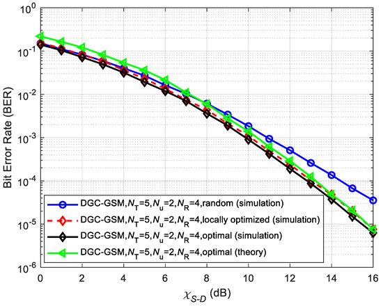
Figure 3.
Performance of our proposed system utilizing and with different selection algorithms.
From the simulation results in Figure 3, it can also be observed that the locally optimized algorithm can achieve almost equal performance with the optimal algorithm in the whole SNR. Furthermore, the locally optimized algorithm has a 73% complexity reduction over the optimal algorithm (as shown in Section 4.3), which reveals the effectiveness of the locally optimized algorithm. Based on this, for the Goppa codes with the large block length, we only consider the system performance ( under the locally optimized algorithm, as illustrated in Figure 4. From the results, superior performance of our proposed optimized algorithm compared to the random selection method is found again. Furthermore, Figure 3 shows the theoretical performance curves under the optimal selection algorithm. It is observed that the theoretical performance is very close to the simulation results at high SNR, which demonstrates the rationality of the theoretical analysis method. Figure 4 compares the theoretical and simulation performances under the locally optimized selection algorithm, and the close match at high SNR again demonstrates the effectiveness of the theoretical analysis approach.
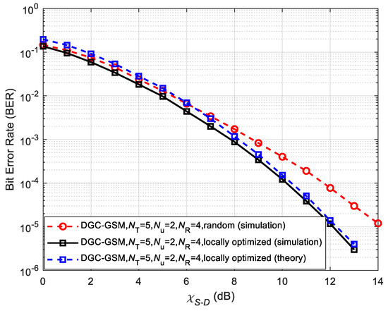
Figure 4.
Performance of our proposed system utilizing and with different selection algorithms.
7.2. Performance of the Proposed Scheme with Different Transmit and Receive Antenna Numbers
To illustrate the effect of the transmit antenna number NT and receive antenna number NR on the system performance, we depict the system performance under different antenna numbers as depicted in Figure 5, Figure 6, Figure 7 and Figure 8. During simulations, the ideal S-R link () is assumed.
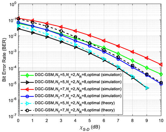
Figure 5.
Performance of our proposed system utilizing and with the optimal algorithm in the case of different NT and NR.
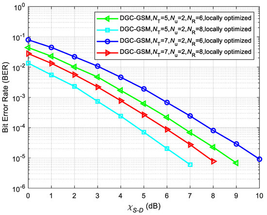
Figure 6.
Performance of our proposed system utilizing and with the locally optimized algorithm in the case of different NT and NR.
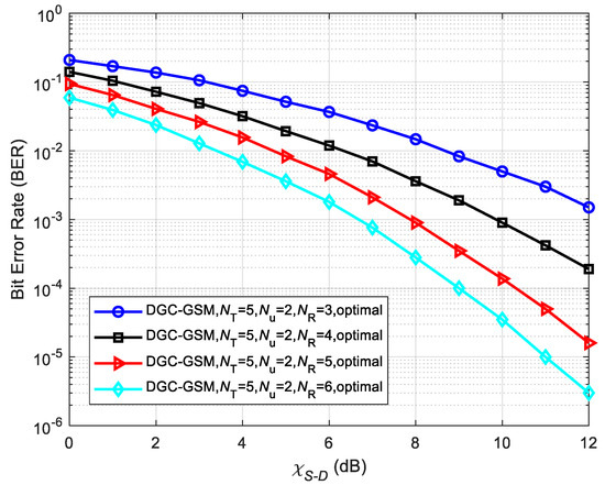
Figure 7.
Performance of our proposed system utilizing and with the optimal algorithm in the case of different NR.
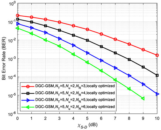
Figure 8.
Performance of our proposed system utilizing and with the locally optimized algorithm in the case of different NR.
The simulation curves in Figure 5 and Figure 6 show the system performance in the case of different transmit antenna numbers NT. We note that reducing NT will help to enhance the overall system performance. For example, at SNR = 10 dB in Figure 5, the performance of achieved under NT = 5 is better than the performance of achieved under NT = 7 for the case of NR = 6. This is because when the modulation order is the same, the system performance is dominated by the transmit antenna number NT, and the error probability is reduced as NT decreases. Furthermore, Figure 5 shows the high match between the theoretical and simulated results at high SNR. Moreover, the theoretical performance is enhanced with the decrease in NT.
From the simulation curves in Figure 7 and Figure 8, it can be clearly observed that increasing NR will greatly improve the system performance. For example, at BER = in Figure 7, the system under NR = 6 has approximately 6 dB, 3 dB, and 1.1 dB SNR gains compared to the system under NR = 3, 4, and 5, respectively. At BER = in Figure 8, the system under NR = 6 obtains approximately 6 dB, 3.2 dB, and 1 dB SNR gains compared to the system under NR = 3, 4, and 5, respectively. This is primarily because the increase in the receive antenna improves the spatial diversity to ensure the performance of the entire system is enhanced.
7.3. Performance of the Proposed Scheme under Different S-R Links and Non-Cooperative Counterpart
Because the practical cooperative communication transmission requires the non-ideal S-R channel, the performance analysis under the non-ideal link is carried out, as shown in Figure 9. We find that the system performance enhances as the S-R link ameliorates. As exhibited in the simulated results, the system performance is poor under the case of the bad S-R link (i.e., , 10 dB, and 11 dB). However, the performance under the better S-R link (i.e., and 13 dB) is very close to that under the ideal link (). Thus, it indicates that the system is relatively sensitive to the noise when 11 dB. However, when , the system is robust. By adopting the cyclic redundancy check (CRC) technology [26], the sensitivity of the system can be further reduced. Additionally, it should be noted that the system performance degradation is primarily due to the fact that wrong decoding at the R leads to error diffusion of the entire cooperative system.
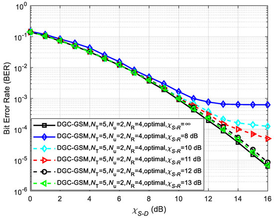
Figure 9.
Performance of the proposed system utilizing and with the optimal algorithm under different S-R links.
Figure 10 shows the performance comparison between the proposed DGC-GSM scheme () and the non-cooperative counterpart under different receiving antenna numbers NR. The non-cooperative scheme denotes the DGC-GSM () with . From Figure 10, it is noted that the proposed coded cooperative scheme exhibits better performance compared to its counterpart under the same NR, which is because the R-D link in the cooperative scenarios has a larger SNR gain than the S-D link. For example, for the case of NR = 6, the coded cooperative system outperforms the non-cooperative system by approximately 0.8 dB at BER .
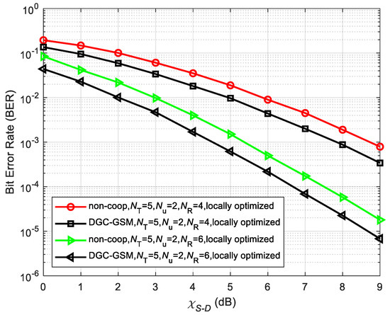
Figure 10.
Performance of the proposed scheme and the non-cooperative system using and with the locally optimized algorithm.
7.4. Performance Comparison between the Proposed Scheme and Existing Strategies
Figure 11 shows the performance comparison between the proposed system (employing and ) and the current system called nested polar-coded cooperative SM (NPCC-SM) [5] under for identical conditions such as an identical equivalent code rate 17/64 (in the D) and the same spectral efficiency of 5 bits/s/Hz. To achieve 5 bits/s/Hz spectral efficiency, the DGC-GSM and NPCC-SM schemes adopt the configurations (NT = 8 and 4-QAM) and (NT = 5, Nu = 2 and 4-QAM), respectively. In [5], the NPCC-SM system does not adopt an optimized encoding method in the relay. In contrast to the literature [5], the proposed system utilizes the locally optimized algorithm to perform effective message selection in the relay to ensure the destination receive the code with a larger minimum distance. Thus, the proposed system is significantly superior to the current system.
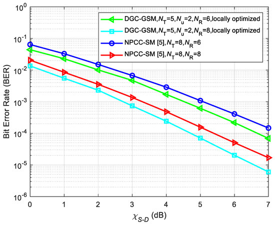
Figure 11.
Performance of the proposed DGC-GSM and the existing system [5].
Furthermore, Figure 12 shows the performance of the DGC-GSM using Algorithm 3 and the existing naive decoding strategy [24], where , and the locally optimized selection algorithm are used. In [24], the existing joint decoding algorithm first decodes the codewords from the S-D and R-D links, and then replaces the partial decoded information of the S-D link by using the whole decoded information of the R-D link. In Algorithm 3, we first decode the codeword from the R-D link to obtain the estimated relay information that is used to replace the partial message of the demodulated codeword from the S-D link, and then utilize the Goppa decoder to perform the decoding for the updated codeword of the S-D link. From the BER curves, it is seen that Algorithm 3 achieves additional performance gains over the existing strategy. This is because Algorithm 3 uses more reliable message from the R-D link as the input of the Goppa decoder that generates the estimated source message.
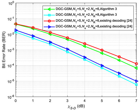
Figure 12.
Performance of the DGC-GSM using Algorithm 3 and the existing decoding strategy [24].
7.5. Performance Comparison between the DGC-GSM and DGC-SM Schemes
Moreover, Figure 13 and Figure 14 compare the performance of the DGC-GSM and its benchmark (i.e., DGC-SM) under in the case of the same spectral efficiency of 5 bits/s/Hz. From the simulation curves, we see the performance of the DGC-GSM and its benchmark is very approximate in the case of an identical NR. However, compared to the transmit antenna number (i.e., NT = 8) of the benchmark, the transmit antenna number (i.e., NT = 5) of the DGC-GSM scheme is significantly reduced. This indicates that in comparison with its counterpart, the proposed DGC-GSM system can achieve a good compromise between the error performance and the complexity of the MIMO configuration. Therefore, the proposed scheme has practical application advantages.
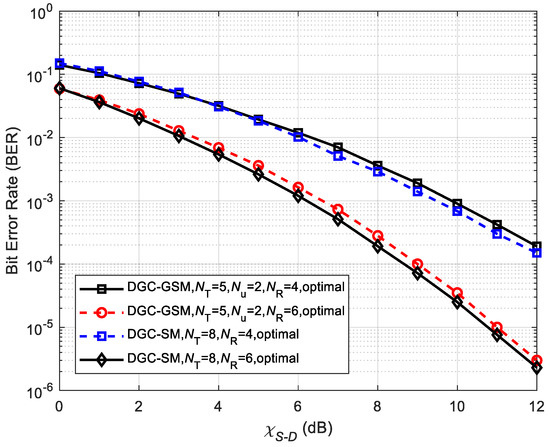
Figure 13.
Performance of the proposed DGC-GSM and its benchmark using and with the optimal algorithm.
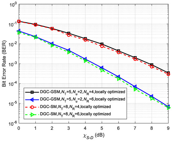
Figure 14.
Performance of the proposed DGC-GSM and its benchmark using and with the locally optimized algorithm.
8. Conclusions
In this paper, the DGC-GSM scheme with the information selection is proposed. With the use of two optimized information selection algorithms, an optimized code is constructed in the destination. To achieve efficient decoding in the destination, the joint decoding algorithm is employed. We investigate the system performance under the proposed two optimized algorithms and the random selection method. Because the code with small number of low-weight codewords is generated in the destination, the optimized algorithms exhibit performance advantages over the random approach. The simulated results also demonstrate that the low-complexity algorithm can achieve near optimal performance. By comparing the simulated results with the theoretical values, the rationality of the theoretical analysis method is confirmed. Furthermore, the proposed DGC-GSM scheme offers better performance gains than the non-cooperative scheme under the identical conditions. The results also reveal the advantages of the proposed strategies over the existing strategies. Moreover, compared to the DGC-SM scheme, the DGC-GSM scheme can achieve nearly the same performance but the transmit antenna number is significantly reduced. Furthermore, the performance of the DGC-GSM scheme will be enhanced with the decrease in the transmit antenna number. Thus, it is good for the reduced transmit antenna number in the proposed system.
Author Contributions
C.Z. conceived the idea. She developed the mathematical models and performed the Monte Carlo simulations. F.Y. checked the mathematical model and the simulated results. D.K.W., C.C., H.X. and L.L. revised the manuscript. All authors have read and agreed to the published version of the manuscript.
Funding
This work was supported by the National Natural Science Foundation of China under the contract No. 61771241.
Data Availability Statement
Not applicable.
Acknowledgments
The authors would like to thank the Editor and anonymous reviewers for their precious suggestions, comments, and reviews that help in improving the quality of this manuscript.
Conflicts of Interest
There is no conflict of interest related to the content of this manuscript.
References
- Huang, K.; Xiao, Y.; Liu, L.; Li, Y.; Song, Z.; Wang, B.; Li, X. Integrated spatial modulation and STBC-VBLAST design toward efficient MIMO transmission. Sensors 2022, 22, 4719. [Google Scholar] [CrossRef] [PubMed]
- Mesleh, R.Y.; Haas, H.; Sinanovic, S.; Ahn, C.W.; Yun, S. Spatial modulation. IEEE Trans. Veh. Technol. 2008, 57, 2228–2241. [Google Scholar] [CrossRef]
- Serafimovski, N.; Renzo, M.D.; Sinanovic, S.; Mesleh, R.Y.; Haas, H. Fractional bit encoded spatial modulation (FBE–SM). IEEE Commun. Lett. 2010, 14, 429–431. [Google Scholar] [CrossRef]
- Wu, Y.; Ying, H.; Jiang, X.; Hai, H. A joint data mapping and detection for high performance generalized spatial modulation. IEEE Commun. Lett. 2019, 23, 2008–2011. [Google Scholar] [CrossRef]
- Mughal, S.; Yang, F.; Xu, H.; Umar, R. Coded Cooperative Spatial Modulation Based on Multi-Level Construction of Polar Code. Telecommun. Syst. 2018, 70, 435–446. [Google Scholar] [CrossRef]
- Shin, J. New mean-squared-error filter design method for multiple-input multiple-output amplify-and-forward relay systems with a non-negligible direct link. Wirel. Pers. Commun. 2022, 125, 3085–3099. [Google Scholar] [CrossRef]
- Devipriya, S.; Manickam, J.M.L.; Anita, X. On the outage performance of decode-and-forward based relay ordering in cognitive wireless sensor networks. Wirel. Netw. 2022, 28, 3247–3259. [Google Scholar] [CrossRef]
- Mughal, S.; Yang, F.; Umar, R. Reed–Muller network coded-cooperation with joint decoding. IEEE Commun. Lett. 2019, 23, 24–27. [Google Scholar] [CrossRef]
- Zhao, C.; Yang, F.; Umar, R.; Mughal, S. Two-source asymmetric turbo-coded cooperative spatial modulation scheme with code matched interleaver. Electronics 2020, 9, 169. [Google Scholar] [CrossRef]
- Fang, Y.; Liew, S.C.; Wang, T. Design of distributed protograph LDPC codes for multi-relay coded-cooperative networks. IEEE Trans. Wirel. Commun. 2017, 16, 7235–7251. [Google Scholar] [CrossRef]
- Liang, H.; Liu, A.; Liu, X.; Cheng, F. Construction and optimization for adaptive polar coded cooperation. IEEE Wirel. Commun. Lett. 2021, 9, 1187–1190. [Google Scholar] [CrossRef]
- Sui, J.; Zhu, X.; Shi, X. MDS and near-MDS codes via twisted Reed–Solomon codes. Des. Code Cryptogr. 2022, 90, 1937–1958. [Google Scholar] [CrossRef]
- Almawgani, A.H.M.; Salleh, M.F.M. RS coded cooperation with adaptive cooperation level scheme over multipath Rayleigh fading channel. cooperation level scheme over multipath Rayleigh fading channel. In Proceedings of the IEEE 9th Malaysia International Conference on Communications (MICC), Kuala Lumpur, Malaysia, 15–17 December 2009. [Google Scholar]
- Almawgani, A.H.M.; Salleh, M.F.M. Coded cooperation using Reed Solomon codes in slow fading channel. IEICE Electron. Expr. 2010, 7, 27–32. [Google Scholar] [CrossRef]
- Guo, P.; Yang, F.; Zhao, C.; Ullah, W. Jointly optimized design of distributed Reed–Solomon codes by proper selection in relay. Telecommun. Syst. 2021, 78, 391–403. [Google Scholar] [CrossRef]
- Jin, L.; Xing, C. New MDS self-dual codes from generalized Reed-Solomon codes. IEEE Trans. Inf. Theory 2017, 63, 1434–1438. [Google Scholar] [CrossRef]
- Chen, B.; Liu, H. New constructions of MDS codes with complementary duals. IEEE Trans. Inf. Theory 2018, 64, 5776–5782. [Google Scholar] [CrossRef]
- Niu, Y.; Yue, Q.; Wu, Y.; Hu, L. Hermitian self-dual, MDS, and generalized Reed-Solomon codes. IEEE Commun. Lett. 2019, 23, 781–784. [Google Scholar] [CrossRef]
- Mora, R.; Tillich, J.P. On the dimension and structure of the square of the dual of a Goppa code. Des. Code Cryptogr. 2023, 91, 1351–1372. [Google Scholar] [CrossRef]
- Gao, Y.; Yue, Q.; Huang, X.; Yang, Y. Two classes of cyclic extended double-error-correcting Goppa codes. ADV. Math. 2022. [Google Scholar] [CrossRef]
- Li, X.; Yue, Q. Construction of expurgated and extended Goppa codes with dihedral automorphism groups. IEEE Trans. Inf. Theory 2022, 68, 6472–6480. [Google Scholar] [CrossRef]
- MacWilliams, F.J.; Sloane, N.J.A. The Theory of Error-Correcting Codes, 3rd ed.; Elsevier: New York, NY, USA, 1977; ISBN 0-444-85009-0. [Google Scholar]
- Bezzateev, S.; Shekhunova, N. Totally decomposed cumulative Goppa codes with improved estimations. Des. Code Cryptogr. 2019, 87, 569–587. [Google Scholar] [CrossRef]
- Zhao, C.; Yang, F.; Waweru, D.K. Reed-Solomon coded cooperative spatial modulation based on nested construction for wireless communication. Radioengineering 2021, 30, 172–183. [Google Scholar] [CrossRef]
- Younis, A.; Serafimovski, N.; Mesleh, R.; Haas, H. Generalised spatial modulation. In Proceedings of the 2010 Conference Record of the Forty Fourth Asilomar Conference on Signals, Systems and Computers, Pacific Grove, CA, USA, 7–10 November 2010; pp. 1498–1502. [Google Scholar]
- Barry, J.R.; Lee, E.A.; Messerschmitt, D.G. Digital Communication, 3rd ed.; Springer: New York, NY, USA, 2004; ISBN 978-1-4615-0227-2. [Google Scholar]


Disclaimer/Publisher’s Note: The statements, opinions and data contained in all publications are solely those of the individual author(s) and contributor(s) and not of MDPI and/or the editor(s). MDPI and/or the editor(s) disclaim responsibility for any injury to people or property resulting from any ideas, methods, instructions or products referred to in the content. |
© 2023 by the authors. Licensee MDPI, Basel, Switzerland. This article is an open access article distributed under the terms and conditions of the Creative Commons Attribution (CC BY) license (https://creativecommons.org/licenses/by/4.0/).