Article

Mobile Robot Path Planning Algorithm Based on RRT_Connect

1
College of Mechanical and Control Engineering, Guilin University of Technology, Guilin 541006, China
2
School of Artificial Intelligence, Hezhou University, Hezhou 542899, China
3
School of Artificial Intelligence and Manufacturing, Hechi University, Yizhou 546300, China
4
Key Laboratory of AI and Information Processing, Education Department of Guangxi Zhuang Autonomous Region, Hechi University, Yizhou 546300, China
*
Author to whom correspondence should be addressed.
Electronics 2023, 12(11), 2456; https://doi.org/10.3390/electronics12112456
Submission received: 6 May 2023 / Revised: 26 May 2023 / Accepted: 27 May 2023 / Published: 29 May 2023

Abstract

:
Targeting some problems of the RRT_Connect path planning algorithm, such as average search and low efficiency, proposes an improved RRT_Connect algorithm that may optimize the searched nodes and parts of planned paths. Firstly, an improved RRT_Connect algorithm based on destination and searched node bias strategy is proposed. Secondly, an improved RRT_Connect algorithm is put forward for the optimization of the searched nodes and some planned paths to deal with the problem of low quality reflected in the improved RRT_Connect path planning algorithm, and the optimization for the cost of path planning by figuring out valid new nodes and parent nodes of adjacent nodes within a certain range. On this basis, the path planning algorithm is verified by simulation and actual experiments. It is shown by the experimental results that the improved RRT_Connect algorithm proposed in this paper can not only shorten the time and length of path planning but also decrease the number of search iterations and nodes.

1. Introduction

Due to population aging, labor costs have gradually risen in recent years. Research on artificial intelligence, deep learning (DL), and other researches in the field of AI and those on robot control technology’s replacement of repetitive work of human beings can greatly improve labor efficiency. Besides, they can help reduce the labor cost of production and manufacturing. Autonomous exploration and execution of mobile robots are based on the good planning of paths, as mobility plays an important role in robot execution [1].
Path planning techniques have evolved into three categories based on their characteristics: traditional path planning (TPP) algorithms, heuristic search-based (HSB) algorithms, and intelligent path planning (IPP) algorithms [2]. The TPP algorithms include the artificial potential field (APF) and simulated annealing (SA) methods. Although the APT method features good real-time performance and smooth planning paths, it may have problems falling into local optimum and oscillation due to excessively close distances [3]. In contrast, the SA method can avoid falling into local optimum, but the results are random and unstable [4]. The HSB algorithms consist of Dijkstra’s algorithm, greedy best-first search (GBFS) algorithm, and A* algorithm [5]. Dijkstra’s algorithm is directionless and inefficient in the search process. The search of the GBFS algorithm is target point-based and efficient, but the shortest planning paths cannot be guaranteed all the time. While the A* algorithm not only reduces the number of search nodes and improves the search efficiency but also ensures that the planning paths are always the shortest [6]. The most common IPP algorithms involve a genetic algorithm (GA) and a rapidly-exploring random tree (RRT) algorithm [7], and the former can obtain the global optimum, with such shortcomings as low algorithm efficiency and premature convergence [8].
In terms of the RRT algorithm, nodes are randomly sampled in the state space through an incremental growth method, and a safe collision-free path from the current position to the target position can always be obtained [9]. Compared with the TPP algorithm, the RRT algorithm, with a wide search range, is free from dividing the space and less likely to fall into local optimum, but it has the disadvantages of low search efficiency, easily convoluted planning paths, and non-optimal paths [10]. Accordingly, the RRT_Connect algorithm has been introduced due to the deficiencies of the RRT algorithm, which simultaneously generates two random trees for expansion in opposite directions at the start point and the target point of the path, thus accelerating the expansion of the sampling space. Despite the shortened planning time, the problem of a large sampling range remains unsolved [11].
An et al. [12] integrated the APF algorithm with the RRT algorithm to help the search process get rid of the local minimum point and thus increase the planning success rate. Zong et al. [13] proposed a regional-sampling RRT (RS-RRT) algorithm, which improves the search efficiency in the sampling phase by combining Gaussian distribution sampling with locally biased sampling. Yuan et al. [14] introduced an efficient bias-goal factor RRT (EBG-RRT) algorithm of path planning for robots in dynamic environments, which exploited relay nodes to obtain the positions where the robots could not collide with dynamic obstacles and to help the robots move without pausing, with high response and success rates. Ghosh et al. [15] presented a bidirectional RRT (Bi-RRT) algorithm based on kinematic constraints, which reduced the nodes generated without affecting the accuracy and produced smooth trajectories by combining with kinematic and dynamic constraints. Ruan et al. [16] put forward a target-oriented RRT path planning algorithm for robots based on sub-target search, introduced a target-oriented function, and designed sub-target search strategies for three different cases. Long et al. [17] proposed an improved Bi-RRT algorithm for path planning in complex environments with multiple narrow intersections, in which virtual target points derived from Dijkstra’s algorithm were set at the narrow intersections and applied to construct the sampling regions. Wang et al. [18] introduced an improved algorithm of the bidirectional RRT_Connect, through which a third node was set between the start point and the target point of the path as the growth point of the random tree, and an adaptive step adjustment function was introduced to prevent the algorithm from falling into local optimum. Lin et al. [19] put forward a non-collision checking RRT* algorithm, which eliminated the collision checking in RRT* extension and applied a collision risk assessment function in the cost function. Zhao et al. [20] suggested combining the APT method with the RRT_Connect algorithm and controlling the generation direction of new nodes by means of a selective heuristic factor to reduce the search range of the ineffective space. Yang et al. [21] introduced a target-biased strategy into the RRT_Connect algorithm to improve the exploration efficiency by guiding the expansion of sampling points toward the target points. Besides, a greedy algorithm was used for pruning, thereby achieving path smoothing. Chen et al. [22] put forward an improved RRT_Connect algorithm that created a third node in the configuration space, allowing the greedy expansion of the algorithm by virtue of a quadtree. Kang et al. [23] applied the bidirectional interpolation method to the RRT_Connect path planning algorithm to smooth the planning path.
The improvement analyses of the RRT algorithm are shown in Table 1. According to the above analyses, the existing improved path planning algorithms based on RRT_Connect have gained some achievements, but the shortcomings of slow convergence rate and convoluted paths still exist. Therefore, an improved RRT_Connect algorithm for optimizing the searched nodes and planned partial paths are provided in this paper. The main contributions of this paper are summarized as follows:
(1)
The bidirectional search algorithm was adopted in the algorithm to increase the convergence rate.
(2)
A target-point and searched-node biased strategy was proposed and applied to the RRT_Connect algorithm to improve the search efficiency.
(3)
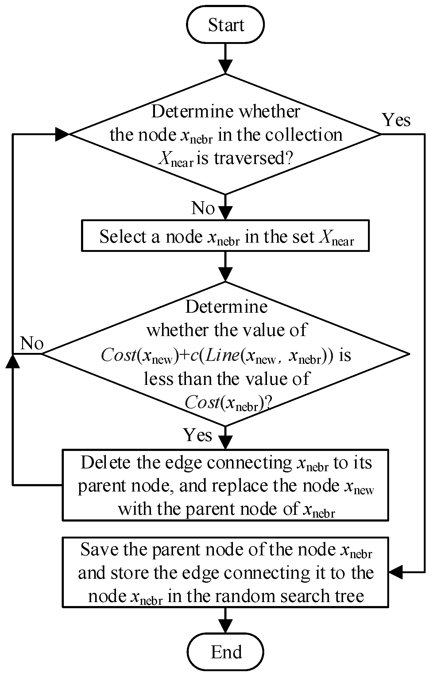
For the purpose of further enhancing the quality of planned paths, the algorithm suggested an improved RRT_Connect algorithm for optimizing searched nodes, and planned partial paths were brought forward for the algorithm by screening effective new nodes and parent nodes of neighboring nodes within a certain range.
The remaining parts of this paper are arranged as follows: The theoretical basis of RRT and RRT_Connect is given in Section 2. The improved RRT_Connect algorithm for optimizing the searched nodes and planned partial paths are discussed in detail in Section 3. In Section 4, the performance of the improved RRT_Connect algorithm is verified and analyzed by designing simulation experiments and actual experiments. The conclusions are presented in Section 5.

2. RRT Algorithm and RRT_Connect Algorithm

2.1. RRT Algorithm

RRT algorithm is a random sampling algorithm using a typical tree structure [24]. It extends the search tree towards the free space by randomly sampling nodes in the state space and uses the specified growth method to build the search tree child nodes. With the increase of the child nodes of the search tree, the search tree grows in the state space. Finally, the shortest distance between the selected point and the target point of a search tree is determined to complete the path planning in the state space. In order to avoid modeling the moving space environment, the algorithm collects the obstacle distribution information in the space by searching whether the child node collides with the obstacle, thus speeding up the search speed and solving the problem of complex computation and high dimension existing in the traditional path planning algorithm. The search process of the RRT algorithm is just like the form of tree growth and branch expansion. The same search method is repeatedly executed in specific and limited iterations. The search tree growth process of the basic RRT algorithm is shown in Figure 1.
In Figure 1, x init represents the root node where the search tree branch grows, x goal represents the end point where the search tree branch expands, and randomly generated sampling points are represented by x rand . The node selected according to the shortest distance from x rand in the search tree T is represented by x near , and the new node extending along the fixed search step steplen with x near as its parent is represented by x new , and its orientation is related to x near and x rand . X free means a free state space without obstacles and X obstacle means an obstacle in a state space.

2.2. RRT_Connect Algorithm

There is a problem of slow convergence in the RRT algorithm due to the random sampling point generation [25]. Therefore, the RRT_Connect algorithm was put forward to raise the convergence rate of the algorithm. The idea of greedy expansion instead of a completely random expansion approach was adopted in the algorithm. Such a heuristic expansion can stimulate faster growth of the two search trees toward each other and thus away from their own constraint space as both the start point and target point are located in the constraint space surrounded by obstacles, thereby greatly shortening the algorithm convergence time [26]. The expansion process of the RTT_Connect algorithm is shown in Figure 2.
In Figure 2, the random tree T1 is on the left side, while the random tree T2 is on the right side. Where x init is the start point of the path planning, x rand refers to the random sampling point, x near denotes the node with the closest distance to x rand in the search tree, and x new indicates the new node expanding along the fixed search step length steplen, with x near as the parent node. One search expansion consisted of two major steps, namely, random expansion and greedy expansion. The random tree T1 performed the random expansion, while the random tree T2 conducted the greedy expansion. The process of the random expansion was the same as that of the traditional RRT algorithm. As for the greedy expansion, the greedy function was determined as a heuristic function. Specifically, T2 produced its new node x new in the direction of the angle between the target point x goal and the new node x new generated by T1, with the same fixed step length steplen of T1. Then the node x new was taken as the parent node by T2 to continuously create new nodes toward the node x new of T1, and the information of the new node was overwritten into the node x new until an obstacle was encountered or the two random trees were successfully connected. If the two random trees were not successfully connected after the greedy expansion, their expansion approaches would be changed for the next search expansion.

3. Improved RRT_Connect Algorithm

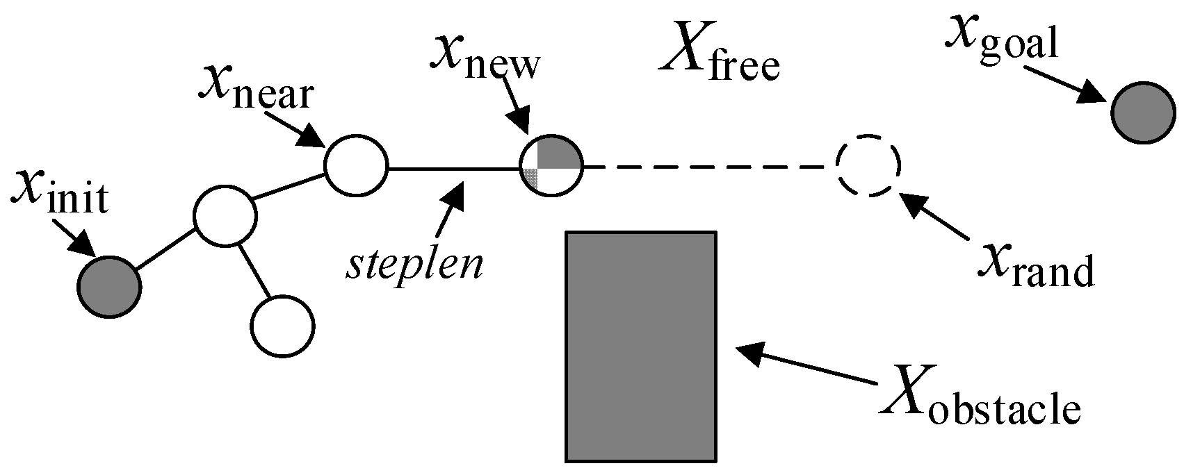
3.1. Improvement of the Random Sampling Function

In the path planning, the random sampling method was subjected to such weaknesses as mediocre search performance and low efficiency. The RRT_Connect algorithm, which improved the search efficiency by means of the bidirectional growth strategy of the two random trees, still faced the challenges brought by non-concentrated sampling areas and large randomness. To overcome the aforementioned problems of this RRT_Connect algorithm in random sampling, a target-point and searched-node biased strategy was developed in this paper under the inspiration of the target-biased concept, where the node information and planned partial paths in the random expansion process of search trees were fully utilized. Moreover, the convergence performance of the algorithm was improved by introducing the reference values of the target-point bias probability and searched-node bias probability, which were expressed as Goalprob and OldNodeprob, respectively, to modify the random sampling function SampleNode(). The random sampling process based on the target point and searched-node bias probability are described below.
Step 1: When the function starts to run, a random real number [0, 1] is generated and assigned to the probability p . The value of label i is a random real number in the range [−1, 0].
Step 2: Judge the probability p . If the probability p is greater than 0 and less than or equal to Goalprob, the random sampling point x rand is set as the target point x goal , and the search tree selects the x near closest to the target point as the parent node to generate x new .
Step 3: If the probability p is greater than the target point bias probability benchmark value and less than or equal to the sum of OldNodeprob and Goalprob, and the searched node cache set is not empty, the random sampling point x rand is set as the node of the corresponding label i in the searched node cache set, and the parent node of x new is x near nearest to the searched node. If the searched node cache set is empty, it indicates that the algorithm is initializing or has not been randomly expanded, and the random sampling point is still set as the target point x goal .
Step 4: If the probability p is greater than the sum of OldNodeprob and Goalprob and less than or equal to 1, then the random sampling point x rand is generated by the SampleNode() function and randomly generated in the finite state space.
Figure 3 shows the flow chart of the improved random sampling function in this paper.

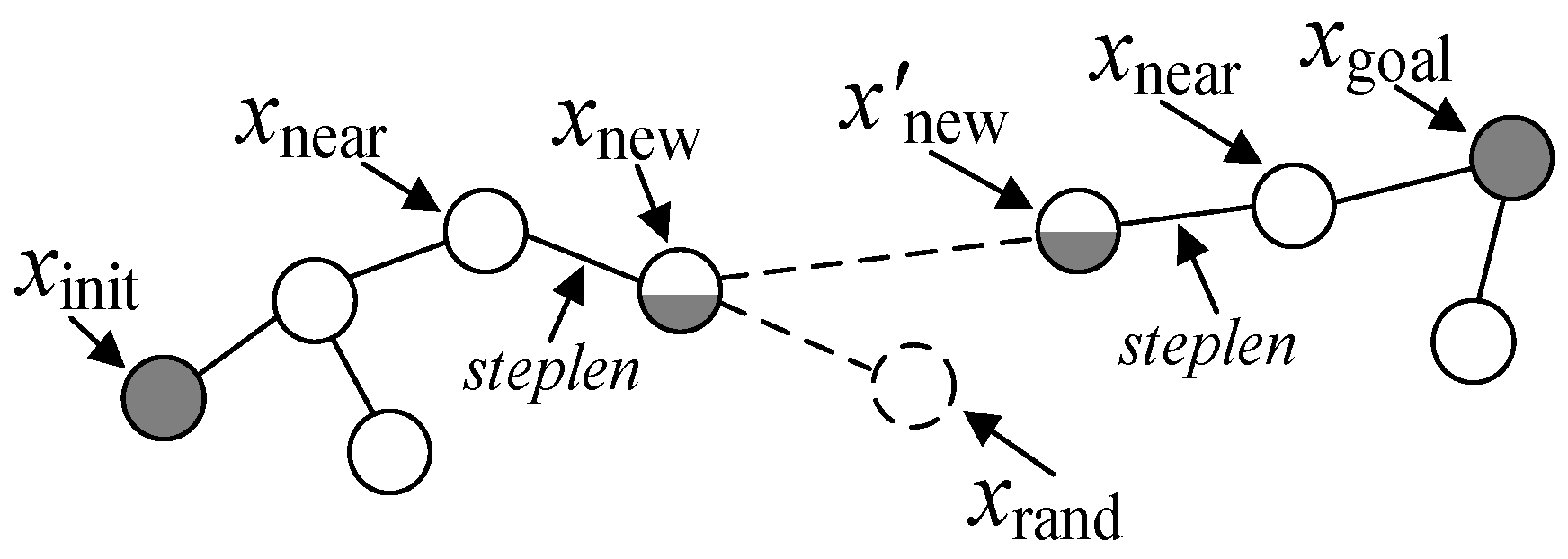
3.2. Improvements of Searched Nodes and Planned Partial Paths

During the improvement of the random sampling function, the use of searched nodes and planned partial paths is not an optimal strategy due to sampling randomness. To improve the quality of searched nodes and planned partial paths, therefore, the randomness of path generation and the selection of parent nodes were optimized for approximating asymptotic optimization. For the convenience of understanding, this paper is defined as follows: x nearest denotes the node closest to sampling point x rand , r near is the radius of the circle with x new as the center, x nebr represents all the searched nodes near x new , and X near is the set of x nebr . Furthermore, the return values of path cost function Cost() was set as the path length of the node x backtracking from the parent node to the root node all along, while that of distance calculation function Line() was defined as the Euclidean distance between the two set nodes, where x min denotes the node x nearest and c min stands for the sum of the path length of the node x nearest backtracking to the root node and the Euclidean distance from the node x nearest to the node x new . Figure 4 shows the flow chart of optimizing the parent nodes of the node x new .
The method of optimizing parent node x new selection is as follows:
Step 1: x new is generated using x nearest as the parent node.
Step 2: With r near as the radius and x new as the center of the circle, the searched node x nebr is searched and the set X near is generated.
Step 3: Define node x min and calculate the value of c min .
Step 4: If node x nebr in the set X near is not traversed, select a node x nebr in the set X near to determine whether the value of C o s t ( x nebr ) + c ( L i n e ( x nebr , x new ) is less than the value of c min . If it is less than c min , the values of the nodes x min and c min  are redefined, and then the iterations within the collection continue. If greater than c min , then continue traversing within the set. If the node x nebr in the collection X near has been traversed, reselect the parent node of node x new , save the parent node of node x new and store its connection edge with node x new in the random search tree.
Figure 5 shows the flow chart of optimizing the searched node x nebr . The method of optimizing parent node selection of searched node x nebr is as follows:
Step 1: If node x nebr in the set X near is not traversed, select a node x nebr in the set X near to determine whether the value of C o s t ( x new ) + c ( L i n e ( x new ,   x nebr ) is less than the value of C o s t ( x nebr ) .
Step 2: If it is less than the value of C o s t ( x nebr ) , the edge connecting x nebr to its parent node is deleted, and the node x new is replaced by the x nebr parent node, and then continue to traverse the inside of the set. If it is greater than the value of C o s t ( x nebr ) , then we continue traversing within the set.
Step 3: If node x nebr in the collection X near has been traversed, save the parent node of node x nebr and store the edge connected to node x nebr in the random search tree.

3.3. Implementation of the Improved RRT_Connect Algorithm

In the traditional RRT_Connect algorithms, the system generates a new node in one tree and then enters another tree for node generation immediately, resulting in the generation of unnecessary nodes and hence the detour of planned paths. To approximate the asymptotic optimal path, an improved RRT_Connect algorithm for optimizing the searched nodes and planned partial paths was proposed. The steps of the improved RRT_Connect algorithm are illustrated below:
Step 1: The algorithm parameters were initialized by setting the root nodes of the random tree T1 and the random tree T2 as start point x init and target point x goal of the planned path, respectively. Then, the random sampling point x rand was generated by the improved random sampling function after the k th iteration.
Step 2: The node x nearest closest to the sampling point x rand on the random tree T1 was selected to generate the node x new with x nearest as the parent node. If the node x new existed and did not collide with an obstacle in the finite state space, it would be taken as the center to plot a circle with a radius of r near . All searched nodes x nebr near x new were found in this circular area and saved as a set in X near . Then the radius r near of the circular area for reselecting the parent nodes was selected as a fixed search step steplen at the beginning of the algorithm. As the algorithm kept conducting iteration and expansion, the radius r near gradually reduced with the increase in the number of searched nodes x nebr on the random trees.
Step 3: The optimal parent node of x new was selected from the set X near generated. First of all, a certain searched node x nebr in X near was chosen. If the connection line between the searched node x nebr and x new did not collide with the obstacle, then the sum of the path length for the node x nebr backtracking to the root node and the Euclidean distance between the node x nebr and x new was calculated and compared with c min . If the sum was smaller than c min , then the searched node x nebr was defined as x min , and the sum of the path cost from the root node to the searched node x nebr and that from x nebr to x new was defined as c min . Afterward, the same collision checking and calculation of the sum of path costs were conducted on other searched nodes in the set X near . If the sum was smaller than c min , then c min and x min were redefined in the same way. Finally, x nebr corresponding to the smallest sum of path costs replaced to become the parent node of x new . The parent node of x new remained to be x nearest if none of the searched nodes in the set X near passed the collision checking or had a smaller sum of the path costs than the initially defined c min .
Step 4: After the optimal parent node x parent of the new node x new was identified, x new with the replaced parent node x parent was added to the random tree T1 and the edge connecting x parent to x new was saved in this random tree.
Step 5: The planned partial path was optimized in the previous circular area for selecting the optimal parent node of x new . All the searched nodes x nebr in the set X near were traversed to perform the following operations: If no collision occurred between the path from the new node x new to a certain selected searched node x nebr and an obstacle, then the sum of the path costs from the root node to x new and from x new to the searched node x nebr was calculated and compared with the path cost from the root node to the searched node x nebr . If the path length from the root node to x new and to x nebr was less than that from the root node to x nebr , then the operation of finding the parent node of x nebr was performed. Afterward, the edge connecting the parent node of x nebr to x nebr in edge set E of the random tree T1 was deleted, and the node x nebr was reconnected to x new to form an edge, which was saved in the edge set E to complete the replacement of the parent node of x nebr by x new .
Step 6: The path planning succeeded when the branches of the random trees T1 and T2 could be connected; otherwise, the path lengths of the two random trees were compared, and the expansion approaches of the two trees were exchanged. Subsequently, the greedy expansion was performed on the random tree with a shorter path, while the random expansion with the steps for improving random sampling and optimizing parent nodes was applied to the other random tree.

4. Experiments and Result Analysis

4.1. Simulation Experiments and Result Analysis

PyCharm Community Edition was used as the simulation platform for path planning. During simulation experiments, the parameters in the literature were slightly adjusted based on the experimental methods [27]. At last, the following constants and variables were set as the algorithm parameters: At the beginning of the experiments, the mobile robot was unfamiliar with the surrounding environment. To enhance the preliminary exploration randomness of the random trees, the target-point bias probability was set as P g = 0.2 . After several simulation experiments, the searched-node bias probability was determined as P r = 0.2 , the expansion step of the random trees was u = 2 , and the initial value 2 was taken as the radius r near of the circular area for reselecting parent nodes. In the connected bidirectional random tree, 0.8 was chosen as the bias probability P d of a random tree growing via greedy expansion towards a new node of another random tree, so as to avoid falling into local optimum. In a rectangle, the distance between the two points on the diagonal is the largest, which can be used to better examine the algorithm performance [28]. Thus, the coordinate position of the start point and the target point were set on the diagonal of the rectangular scenes in the present simulation experiments.
Here, three scenes for simulation experiments were designed, including a multi-type obstacle scene, a well-shaped surrounding obstacle scene, and a long passage obstacle scene, so as to compare and verify the performance of the traditional RRT_Connect algorithm and the improved RRT_Connect algorithm proposed in this paper in the simulation experiments on path planning.
(1) Experimental scene 1: multi-type obstacle scene
The multi-type obstacle scene had the resolution of 56 × 36, and the main body of a symmetrical structure constituted by six gray circular obstacles and two gray rectangular obstacles. The coordinates of the start point (red) and the target point (blue) of mobile robot model X were (0, 30) and (50, 0), respectively, and the maximum number of iterations was determined as T max = 750 . The two algorithms aforesaid were applied to path planning in this scene, with the planned path shown in Figure 6a,b.
In Figure 6, Figure 6a is the planning roadmap of the RRT_Connect algorithm in the multi-type obstacle scene, and Figure 6b is the planning roadmap of the improved algorithm in the multi-type obstacle scene. Those of the two bidirectional random trees are illustrated by green and yellow lines, respectively, and the paths finally searched by these two algorithms were represented by red lines. As clearly seen in the figure, both algorithms found a path that could successfully pass through the multi-type obstacles in experimental scene 1. The traditional RRT_Connect algorithm showed a relatively straight path during the greedy expansion, while there were turns in other parts of the path. In comparison, the planned path optimized by the improved RRT_Connect algorithm was straight and reasonable, with fewer turns, and the mobile robot passed experimental scene 1 at a close distance to the inner side of the obstacles. Here, the performance of the two algorithms was compared by calculating the average values of such indices as the pathfinding time, length of the planned path, number of search iterations, and number of search iteration nodes after 100 times of running. According to Table 2, the improved RRT_Connect algorithm exhibited a shorter pathfinding time and fewer search iterations (127 times) under the multi-type obstacle scene. In terms of the number of search iteration nodes, the improved algorithm generated 75 new nodes, while the traditional one generated 77 new nodes. These results indicated the high search efficiency of the improved algorithm, thereby reducing the loss of the system memory. In addition, the improved RRT_Connect algorithm presented fewer turns, a higher planning success rate, and better performance in overall path planning.
(2) Experimental scene 2: well-shaped surrounding obstacle scene
The main body of the well-shaped surrounding obstacle scene with the resolution of 56 × 36 was a well-shaped structure composed of four gray rectangular obstacles. The coordinates of the start point (red) and the target point (blue) of the mobile robot model X were (0, 0) and (50, 30), respectively, and the maximum number of iterations was set as T max = 1000 . In this scene, the two different algorithms were used for path planning, with the planned paths shown in Figure 6c,d. Respectively, Figure 6c is a planning roadmap of the RRT_Connect algorithm in the well-shaped surrounding obstacle scene and Figure 6d is a planning roadmap of the improved algorithm in the well-shaped surrounding obstacle scene. Those of the two bidirectional random trees are illustrated by green and yellow lines, respectively, and the paths finally searched by these two algorithms were represented by red lines. It was clearly displayed in the figure that the two algorithms were capable of identifying a smooth path through well-shaped obstacles in experimental scene 2. The path of the traditional RRT_Connect algorithm was severely curved with more turns, while the improved algorithm effectively reduced the number of turns and maximized the path straightness by optimizing the planned path.
The performance index data of the two algorithms after 100 times of running in this experiment were recorded, and the average values were calculated for comparison (Table 2). It was manifested that in the well-shaped surrounding obstacle scene, the improved RRT_Connect algorithm still obtained fewer search iterations, search iteration nodes, and turns, as well as a higher planning success rate on average. In addition, it was 10.29% faster than the traditional RRT_Connect algorithm in planning the paths. Overall, the improved RRT_Connect algorithm outperformed the traditional one in path planning in experimental scene 2.
(3) Experimental scene 3: long passage obstacle scene
The long passage obstacle scene was configured with the resolution of 56 × 36, and a long passage constituted by four gray rectangular obstacles as the main body. The coordinates of the start point (red) and the target point (blue) of the mobile robot model X were (0, 30) and (50, 0), respectively, and the maximum number of iterations was set as T max = 1400 . In this scene, the paths were planned by means of the two algorithms mentioned above (Figure 6e,f). Respectively, Figure 6e is the planning roadmap of the RRT_Connect algorithm in long passage obstacle scene, and Figure 6f is the planning roadmap of the improved algorithm in the long passage obstacle scene. Those of the two bidirectional random trees are illustrated by green and yellow lines, respectively, and the paths finally searched by these two algorithms were represented by red lines.
It was distinctly illustrated in Figure 6e,f that after the optimization of the planned paths, the improved RRT_Connect algorithm significantly reduced the turns of the mobile robot and hence generated a shortened planned path with improved quality compared with the traditional algorithm.
The performance index data of the two algorithms run 100 times in this experiment were recorded, and the average values were calculated for performance comparison (Table 2). According to the table, the improved RRT_Connect algorithm spent less time on planning the suboptimal path in experiment scene 3, 29.53%faster than the traditional algorithm. Besides, the average length of the planned path obtained by the improved RRT_Connect algorithm was less than 90 m, and the number of search iterations was over 400, smaller than that of the traditional RRT_Connect algorithm (over 500). Moreover, regarding the number of search iteration nodes, the improved RRT_Connect algorithm generated 11.23% fewer new nodes than the traditional one (160 new nodes). Furthermore, the improved RRT_Connect algorithm also displayed fewer turns and a higher planning success rate on average.
Figure 6. Planning roadmap of two different algorithms in three different obstacle scenes. (a) Planning roadmap of the RRT_Connect algorithm in the multi-type obstacle scene; (b) Planning roadmap of the improved algorithm in the multi-type obstacle scene; (c) Planning roadmap of the RRT_Connect algorithm in the well-shaped surrounding obstacle scene; (d) Planning roadmap of the improved algorithm in the well-shaped surrounding obstacle scene; (e) Planning roadmap of the RRT_Connect algorithm in long passage obstacle scene; (f) Planning roadmap of the improved algorithm in long passage obstacle scene.
Electronics 12 02456 g006aElectronics 12 02456 g006b
Table 2. Performance comparison of two different algorithms in three different obstacle scenes. (100 times).
Experimental Scene 1: Multi-Type Obstacle Scene
AlgorithmRRT_Connect AlgorithmImproved RRT_Connect Algorithm
average pathfinding time (s)12.3413.84
average length of the planned path (m)80.4964.75
average number of search iterations (times)125.56117.15
average number of search iteration nodes76.9875.13
average number of turns (times)17.007.00
average planning success rate (%)95.0096.00
Experimental Scene 2: Well-Shaped Surrounding Obstacle Scene
AlgorithmRRT_Connect AlgorithmImproved RRT_Connect Algorithm
average pathfinding time (s)36.3532.61
average length of the planned path (m)89.6870.72
average number of search iterations (times)355.91308.89
average number of search iteration nodes137.64126.06
average number of turns (times)15.006.00
average planning success rate (%)88.0090.00
Experimental Scene 3: Long Passage Obstacle Scene
AlgorithmRRT_Connect AlgorithmImproved RRT_Connect Algorithm
average pathfinding time (s)47.1233.20
average length of the planned path (m)105.8585.83
average number of search iterations (times)548.36428.76
average number of search iteration nodes157.48139.79
average number of turns (times)20.006.00
average planning success rate (%)85.0088.00
Combined with the results of the above three experimental scenes, the path planning performance of the two algorithms was found to decline to a certain extent with the change of obstacles and the length increase of the planned path. The improved RRT_Connect algorithm not only inherited the bidirectional search characteristics of the traditional RRT_Connect algorithm but also adopted the target-point and searched-node biased strategy, thus substantially reducing the path planning time. In the meantime, by optimizing the searched nodes and planned partial paths, the improved RRT_Connect algorithm decreased the length of the planned path by an average of 20% compared with the traditional RRT_Connect algorithm. Moreover, fewer search iterations and effective new nodes obtained by the improved RRT_Connect algorithm indicated the high search efficiency and less memory occupation of the improved RRT_Connect algorithm, thus effectively reducing the loss of the robot controller. Furthermore, fewer turns and higher planning success rates on average demonstrated the better performance of the improved RRT_Connect algorithm than the traditional RRT_Connect algorithm in path planning. The above experiments proved that the improved RRT_Connect algorithm has superior performance in path planning.

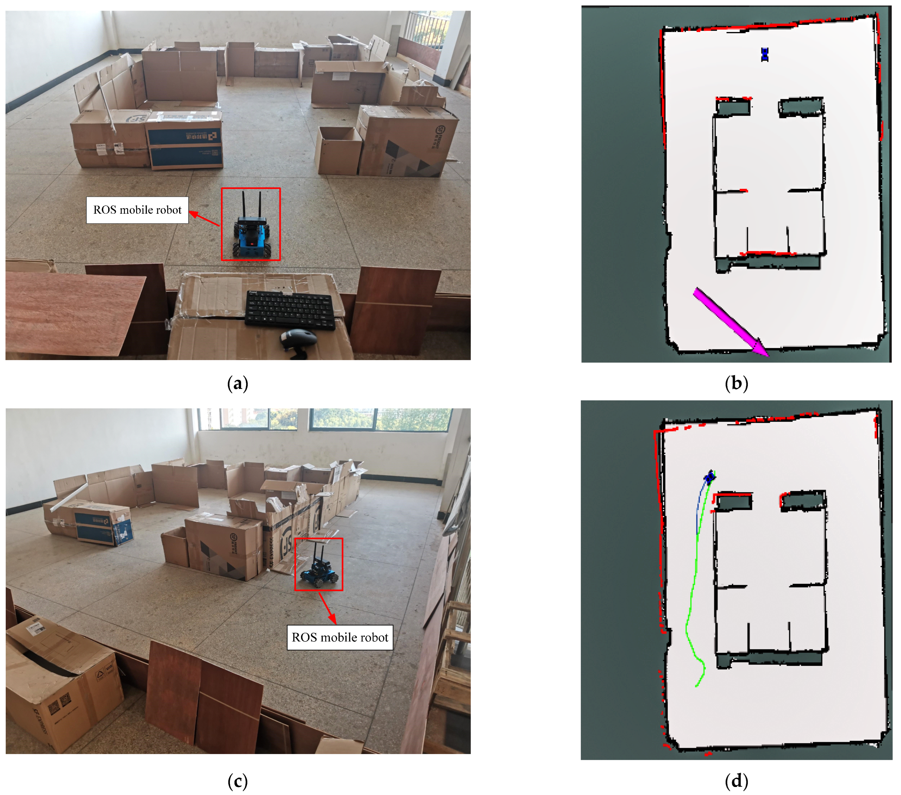
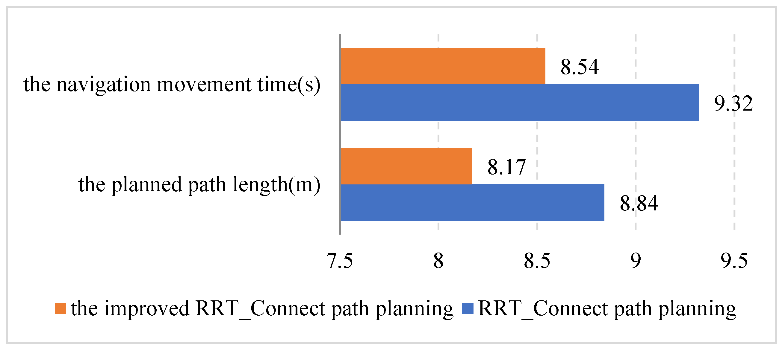
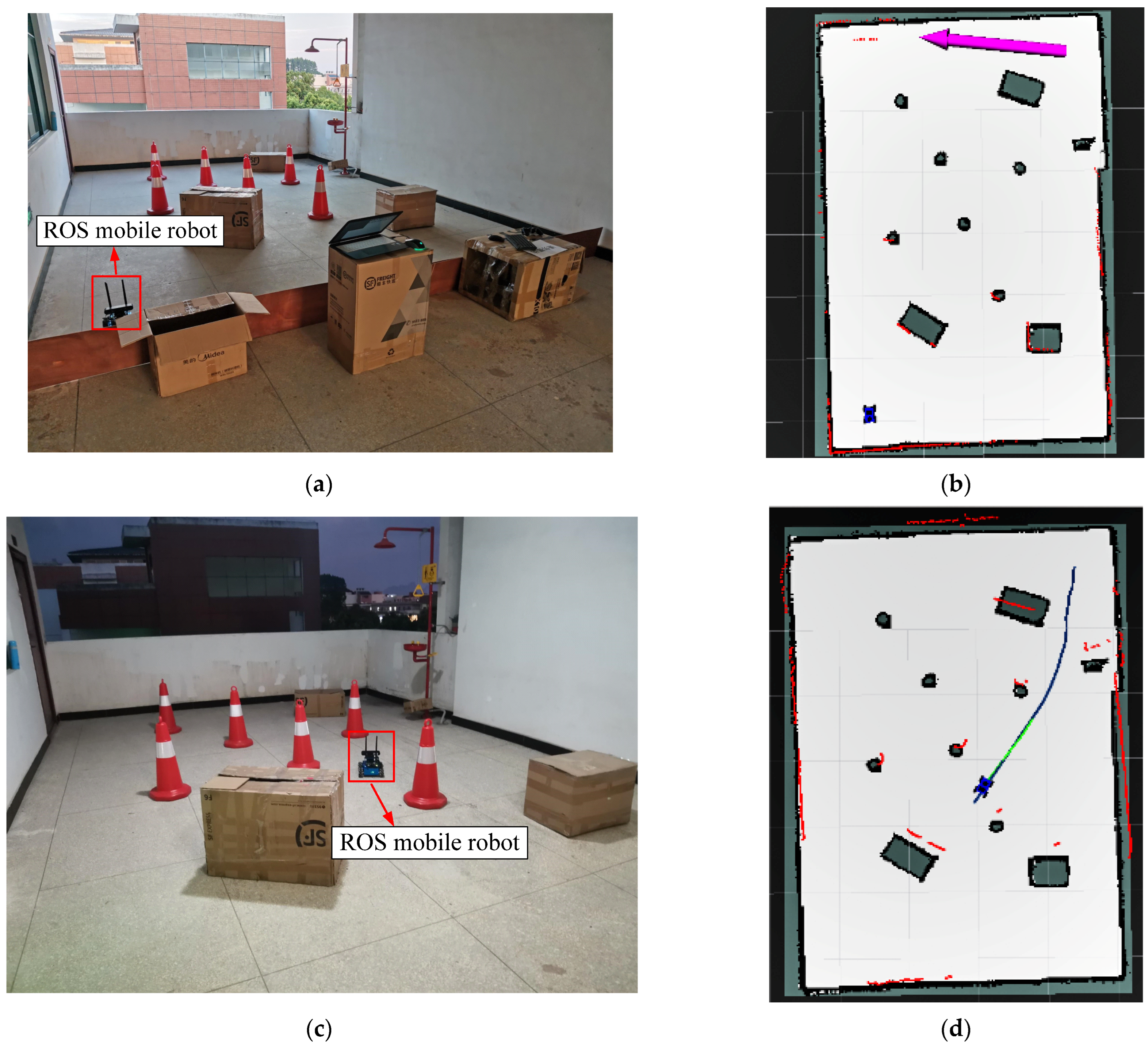
4.2. Experiments in Actual Scenes and Result Analysis

Given the limitations in the size of open space and the number of experimental tools, as well as the work time of the robot’s battery and the strength of the outdoor wireless communication signal, two actual obstacle scenes were constructed indoors in this research, including a simple obstacle scene with an area of 6.08 × 7.12 m2 and a complex obstacle scene with an area of 5.12 × 6.95 m2, both surrounded by wooden boards and cartons. Specifically, the former only had obstacles surrounded by cartons, while the latter were configured with circular cone buckets and rectangular cartons. These two different scene maps were used to examine the validity and feasibility of the planned path obtained by the improved RRT_Connect algorithm and to compare it with the traditional RRT_Connect algorithm. The mobile robot had a physical size of 0.25 m × 0.22 m × 0.2 m, a maximum linear velocity of 0.35 m/s, a maximum angular velocity of 0.63 rad/s, a maximum linear acceleration of 0.25 m/s, and a maximum angular acceleration of 0.8 rad/s. Other settings included the maximum measurement distance of the laser radar (12 m), the accuracy of the robot free passage map (0.01 m), and the inflation radius of the costmap (0.55 m).
(1) Actual scene 1: simple obstacle scene
The mobile robot was initially located directly above the actual obstacle scene, as shown in Figure 7a, which was navigated by the two different path planning algorithms in actual scene 1. The algorithm operation effects in the beginning, middle and final stages of navigation in this scene are presented in Figure 7a,c,e, respectively, and their display effects in the visualization tool RViz are exhibited in Figure 7b,d,f, respectively.
In Figure 7b, the navigation positions and directions set in the path planning experiment are represented by purple arrows. Green lines and light blue lines in Figure 7d stand for the global planning paths and the local planning paths, respectively. In Figure 7f, the blue car model represents the model of the omnidirectional mobile autonomous robot with Mecanum wheels in RViz, and the red dot matrix indicates the lidar scanning data.
Besides, the navigation movement time and the planned path length in actual scene 1 obtained by the two different path planning algorithms were recorded for performance comparison. According to the results in Figure 8, in actual scene 1, the navigation movement time and the planned path length obtained by the improved RRT_Connect algorithm were reduced by 0.78 s and 0.67 m, respectively, in contrast with those of the traditional one. In general, the improved RRT_Connect algorithm outperformed the traditional one in path planning.
(2) Actual scene 2: complex obstacle scene
The mobile robot was initially placed at the top right of the actual obstacle scene (Figure 9a) and then navigated by the two different path planning algorithms in actual scene 2. The algorithm operation effects in the beginning, middle and final stages of navigation in the actual scene are shown in Figure 9a,c,e, respectively, with the respective display effects in the RViz listed in Figure 9b,d,f, respectively. The values of such indices as the navigation movement time and the planned path length during the operation of the two path planning algorithms in actual scene 2 are compared in Figure 10, indicating certain increases in these values obtained by both path planning algorithms. In terms of the navigation movement time, the improved RRT_Connect algorithm presented 21.45% faster navigation movement and 26.45% shorter planned path than the traditional RRT_Connect algorithm. The overall path planning performance of the improved RRT_Connect algorithm was significantly superior to that of the traditional one.
It was revealed by the results of the two actual obstacle scenes that the navigation movement time and planned path length of both path planning algorithms were raised with the increase of obstacles in the scene grid map. Nonetheless, the improved RRT_Connect algorithm always exhibited a shorter autonomous navigation movement time and a lower path cost than the traditional RRT_Connect algorithm. In addition, the more complex the scene grid map was, the greater the differences between the two algorithms in the navigation performance index values would be, suggesting that the improved RRT_Connect algorithm is featured by high search efficiency of random trees and good optimization of navigation path planning, and superior performance in autonomous navigation compared to the traditional RRT_Connect algorithm. The above-mentioned experimental results validated the validity and feasibility of the path planning conducted by the improved RRT_Connect algorithm.

5. Conclusions

While conducting random sampling in a given search space, the traditional RRT_Connect algorithm is inclined to collect excessive samples in the ineffective space, causing a large computational cost. Hence, an improved RRT_Connect algorithm for optimizing the searched nodes and planned partial paths was proposed in this paper. The following conclusion has been drawn through theoretical research and simulation experiments:
(1)
Firstly, based on the goal-biased concept, a target-point and searched-node biased strategy was developed, which introduced the reference values of the target-point bias probability and searched-node bias probability into the random sampling function, thereby increasing the search efficiency by setting the random sampling point as the target point or searched node according to the random probability. Next, an improved RRT_Connect algorithm for optimizing the searched nodes and planned partial paths was formulated, which reduced the cost of path planning and improved the quality of planned paths by filtering new effective nodes and parent nodes of neighboring nodes within a certain range.
(2)
Simulation experiments and actual scene experiments were carried out to verify the improved RRT_Connect algorithm and compare it with the traditional RRT_Connect algorithm. The experimental results manifested that the improved RRT_Connect algorithm decreased the time and length of path planning, reduced the number of search iterations and newly generated nodes, accelerated convergence of the algorithm, and lowered the energy consumption of the system memory.
(3)
Although the improved RRT_Connect algorithm outperformed the traditional algorithm by improving the search efficiency and the quality of planned paths, it was still subjected to great variation in the length of optimized paths due to the characteristics of random sampling, inducing the necessary processes of evaluation, screening or filtering in path optimization. Furthermore, in the present research on path planning, the designed simulation scenes and actual scenes were all in static states despite certain complexity. In the future, therefore, dynamic scenes, including dynamic obstacles and dynamic target points, should be incorporated for further research and discussion.

Author Contributions

Conceptualization, L.Z.; Methodology, J.Z. and X.S.; Software, X.S. and L.T.; Investigation, Y.Y. and J.P.; Writing—original draft, X.S. and J.Z.; Writing—review & editing, J.P.; Supervision, L.T. and L.Z.; Project administration, L.Z. All authors have read and agreed to the published version of the manuscript.

Funding

This research was funded by National Natural Science Foundation of China (No. 62063006); Key Laboratory of AI and Information Processing (Hechi University), Education Department of Guangxi Zhuang Autonomous Region (No. 2022GXZDSY003); Guangxi Key Laboratory of Spatial Information and Geomatics (Guilin University of Technology) (No. 19-185-10-08); Innovation Project of Guangxi Graduate Education (No. YCSW2023352).

Data Availability Statement

The data presented in this study are available on request from Xiaoxu Shi.

Acknowledgments

Authors express their gratitude to the reviewers for improving this work.

Conflicts of Interest

The authors declare no conflict of interest.

References

  1. Ullah, I.; Shen, Y.; Su, X.; Esposito, C.; Choi, C. A localization based on unscented Kalman filter and particle filter localization algorithms. IEEE Access 2020, 8, 2233–2246. [Google Scholar] [CrossRef]
  2. Shi, Z.; Mei, S.; Shao, Y.; Wan, R.; Song, Z.; Xie, M.; Li, Y. Research status and Prospect of mobile robot path planning based on artificial potential field method. China J. Agric. Mach. Chem. 2021, 42, 182–188. [Google Scholar]
  3. Pan, Z.; Zhang, C.; Xia, Y.; Xiong, H.; Shao, X. An Improved Artificial Potential Field Method for Path Planning and Formation Control of the Multi-UAV Systems. IEEE Trans. Circuits Syst. II-Express Briefs 2022, 69, 1129–1133. [Google Scholar] [CrossRef]
  4. Tang, F.; Pedrycz, W. An improved DV-Hop algorithm based on differential simulated annealing evolution. Int. J. Sens. Netw. 2022, 38, 1–11. [Google Scholar] [CrossRef]
  5. Wen, J.; Yang, J.; Wang, T. Path planning for autonomous underwater vehicles under the influence of ocean currents based on a fusion heuristic algorithm. IEEE Trans. Veh. Technol. 2021, 70, 8529–8544. [Google Scholar] [CrossRef]
  6. Cao, R.; Zhang, Z.; Li, S.; Zhang, M.; Li, H.; Li, M. Multi machine collaborative global path planning based on improved A~* algorithm and Bezier curve. J. Agric. Mach. 2021, 52, 548–554. [Google Scholar]
  7. Gao, M.; Tang, H.; Zhang, P. Research status of robot cluster path planning technology. J. Natl. Univ. Def. Technol. 2021, 43, 127–138. [Google Scholar]
  8. Xu, X.; Yu, X.; Zhao, Y.; Liu, C.; Wu, X. Global path planning of mobile robot based on improved genetic algorithm. Comput. Integr. Manuf. Syst. 2022, 28, 1659–1672. [Google Scholar]
  9. Meng, B.H.; Godage, I.S.; Kanj, I. RRT*-Based Path Planning for Continuum Arms. IEEE Robot. Autom. Lett. 2022, 7, 6830–6837. [Google Scholar] [CrossRef]
  10. Yi, J.; Yuan, Q.; Sun, R.; Bai, H. Path planning of a manipulator based on an improved P_RRT* algorithm. Complex Intell. Syst. 2022, 8, 2227–2245. [Google Scholar] [CrossRef] [PubMed]
  11. Chen, Y.; Fu, Y.; Zhang, B.; Fu, W.; Shen, C. Path planning of the fruit tree pruning manipulator based on improved RRT-Connect algorithm. Int. J. Agric. Biol. Eng. 2022, 15, 177–188. [Google Scholar] [CrossRef]
  12. An, H.; Hu, J.; Lou, P. Obstacle Avoidance Path Planning Based on Improved APF and RRT. In Proceedings of the 2021 4th International Conference on Advanced Electronic Materials, Computers and Software Engineering (AEMCSE), Changsha, China, 26–28 March 2021; IEEE: Piscataway, NJ, USA, 2021; pp. 1028–1032. [Google Scholar]
  13. Zong, C.; Han, X.; Zhang, D.; Liu, Y.; Zhao, W.; Sun, M. Research on local path planning based on improved RRT algorithm. Proc. Inst. Mech. Eng. Part D J. Automob. Eng. 2021, 235, 2086–2100. [Google Scholar] [CrossRef]
  14. Yuan, C.; Liu, G.; Zhang, W.; Pan, X. An efficient RRT cache method in dynamic environments for path planning. Robot. Auton. Syst. 2020, 131, 103595. [Google Scholar] [CrossRef]
  15. Ghosh, D.; Nandakumar, G.; Narayanan, K.; Honkote, V.; Sharma, S. Kinematic Constraints Based Bi-directional RRT (KB-RRT) with Parameterized Trajectories for Robot Path Planning in Cluttered Environment. In Proceedings of the 2019 International Conference on Robotics and Automation (ICRA), Montreal, QC, Canada, 20–24 May 2019; IEEE: Piscataway, NJ, USA, 2019; pp. 8627–8633. [Google Scholar]
  16. Ruan, X.; Zhou, J.; Zhang, J.; Zhu, X. Robot target oriented RRT path planning algorithm based on sub target search. Control. Decis. Mak. 2020, 35, 2543–2548. [Google Scholar]
  17. Long, J.; Liang, Y. Improved Bi RRT path planning under multiple narrow intersections. Instrum. Technol. Sens. 2019, 436, 118–123. [Google Scholar]
  18. Wang, K.; Huang, B.; Zeng, G.; Li, X. Fast path planning algorithm based on improved RRT connect. J. Wuhan Univ. Sci. Ed. 2019, 65, 283–289. [Google Scholar]
  19. Lin, Y.; Chen, Y.; He, B.; Huang, Y.; Wang, Y. Mobile robot motion planning method without collision detection RRT~*. J. Instrum. 2020, 41, 257–267. [Google Scholar]
  20. Zhao, C.; Ma, X.; Zhang, C.; Mu, C. RRT connect path planning algorithm based on gravitational field guidance. Electron. Meas. Technol. 2021, 44, 44–49. [Google Scholar]
  21. Yang, H.; Li, H.; Liu, K.; Yu, W.; Li, X. Research on path planning based on improved RRT-Connect algorithm. In Proceedings of the 2021 33rd Chinese Control and Decision Conference (CCDC), Kunming, China, 22–24 May 2021; IEEE: Piscataway, NJ, USA, 2021; pp. 5707–5712. [Google Scholar]
  22. Chen, J.; Zhao, Y.; Xu, X. Improved RRT-Connect Based Path Planning Algorithm for Mobile Robots. IEEE Access 2021, 9, 145988–145999. [Google Scholar] [CrossRef]
  23. Kang, T.W.; Kang, J.G.; Jung, J.W. A Bidirectional Interpolation Method for Post-Processing in Sampling-Based Robot Path Planning. Sensors 2021, 21, 7425. [Google Scholar] [CrossRef]
  24. Veras, L.; Medeiros, F.; Guimaraes, L. Systematic literature review of sampling process in Quick-exploring random trees. IEEE Access 2019, 7, 50933–50953. [Google Scholar] [CrossRef]
  25. Wang, D.; Zheng, S.; Ren, Y.; Du, D. Path Planning Based on the Improved RRT* Algorithm for the Mining Truck. CMC–Comput. Mater. Contin. 2022, 71, 3571–3587. [Google Scholar] [CrossRef]
  26. Wang, H.; Gao, M.; Wang, J.; Fang, L.; Li, H. Multi scene motion planning of manipulator based on improved rrt~*-connect algorithm. J. Agric. Mach. 2022, 53, 432–440. [Google Scholar]
  27. Wang, Y. Research on Path Planning Method of Wheeled Robot Based on RRT; Tianjin University of Technology: Tianjin, China, 2019. [Google Scholar]
  28. Qi, J.; Yang, H.; Sun, H. MOD-RRT*: A Sampling-Based Algorithm for Robot Path Planning in Dynamic Environment. IEEE Trans. Ind. Electron. 2021, 68, 7244–7251. [Google Scholar] [CrossRef]
Figure 1. Realistic view of experimental environment.
Electronics 12 02456 g001
Figure 2. RRT_Connect algorithm expansion process diagram.
Electronics 12 02456 g002
Figure 3. Flow chart of improved random sampling function.
Electronics 12 02456 g003
Figure 4. Flow chart of optimizing parent node x new selection.
Electronics 12 02456 g004
Figure 5. Flow chart of optimizing parent node selection of searched node x nebr .
Electronics 12 02456 g005
Figure 7. Path planning for the mobile robot in actual scene 1. (a) Beginning of robot navigation; (b) Beginning of RViz navigation; (c) Middle stages of robot navigation; (d) Middle stages of RViz navigation; (e) Final stages of robot navigation; (f) Final stages of RViz navigation.
Electronics 12 02456 g007aElectronics 12 02456 g007b
Figure 8. Comparison of navigation performance index values between the two path planning algorithms in actual scene 1.
Electronics 12 02456 g008
Figure 9. Path planning for the mobile robot in actual scene 2. (a) Beginning of robot navigation; (b) Beginning of RViz navigation; (c) Middle stages of robot navigation; (d) Middle stages of RViz navigation; (e) Final stages of robot navigation; (f) Final stages of RViz navigation.
Electronics 12 02456 g009aElectronics 12 02456 g009b
Figure 10. Comparison of navigation performance index values between the two path planning algorithms in actual scene 2.
Electronics 12 02456 g010
Table 1. Improvement analyses of the RRT algorithm.
ReferencesImprovement StrategiesAdvantagesLimitations
[12]Combine with the APF algorithm and introduce a heuristic factor into RRTImprove the speed and success rate of planningNon-optimal path
[13]Combine with Gaussian distribution sampling and local bias samplingImprove the search efficiency in the sampling phaseLarge amount of data and long search time
[14]The relay node method is introducedPlanning path in a dynamic environment in real-timeHigh path cost
[15]Combining kinematic constraints to limit the number of nodesAdapt to a complex environmentYou have to use the kinematic equation to constrain the equation
[16]Introduce a goal-directed functionIt can solve the local minimal problem easily encountered in local path planningComputationally heavy
[17]Introduce a virtual target area for navigationHandle multiple narrow intersections environment wellPlanned path zigzag
[18]The third node is selected as the extension point, and the adaptive step size adjustment function is introducedImprove the efficiency of path planning and reduce the number of iterationsOnly adapt to a simple environment with fewer obstacles
[19]Add a collision risk assessment function to the cost functionStrong obstacle avoidance ability and high wayfinding efficiency.Path quality difference
[20]The third node is selected as the new extension node, and a gravitational field is superimposed on each node to guide the direction of node generationFast response speed and high success ratePoor continuity
[21]Introduce the target bias policyImprove exploration efficiency and achieve path smoothingComputationally heavy
[22]Introduce a third node and target bias policyHigh search efficiencyIt doesn’t fit into three dimensions
[23]The bidirectional interpolation method is introducedShort path length and fast planning efficiencyPoor reliability and oscillations
Disclaimer/Publisher’s Note: The statements, opinions and data contained in all publications are solely those of the individual author(s) and contributor(s) and not of MDPI and/or the editor(s). MDPI and/or the editor(s) disclaim responsibility for any injury to people or property resulting from any ideas, methods, instructions or products referred to in the content.

