Article

Multi-Parameter Optimization of Stator Coreless Disc Motor Based on Orthogonal Response Surface Method

School of Electrical Engineering, Hebei University of Science and Technology, Shijiazhuang 050018, China
*
Authors to whom correspondence should be addressed.
Electronics 2023, 12(14), 3020; https://doi.org/10.3390/electronics12143020
Submission received: 17 June 2023 / Revised: 6 July 2023 / Accepted: 7 July 2023 / Published: 10 July 2023

Abstract

:
In response to the structural optimization problem of PCB stator coreless disc motors, the orthogonal response surface method was used to optimize the motor structure, preliminarily determine the basic parameters of the motor, and conduct orthogonal experiments on the motor parameters based on the optimization design objectives. The optimization factors were the quantity of the magnetic pole of the motor rotor p, the ratio of the main/auxiliary pole sizes Rnd, the thickness Tm of the permanent magnet, and the air gap length δ. The motor torque Td, the amplitude of the magnetic density of the air gap Bδ, and the waveform distortion rate THD were used as optimization objectives. The motor parameters that cause the motor torque to reach a maximum cause the air gap magnetic density to reach a maximum and the waveform distortion rate to reach a minimum. Due to the use of PCB plates instead of motor stator cores in the PCB coreless disc motors, the service life of the PCB board during motor operation will be reduced with the temperature increase generated by the stator winding. To solve this problem, a response surface analysis of the motor was carried out to reduce the increase in the temperature of the stator windings during the operation of the motor. The PCB board and stator winding are the main factors affecting the motor’s temperature increase. Taking the thickness of the PCB board, the hole diameter on the board, and the uneven width of the stator winding as optimization factors, the motor parameters with the lowest increase in the temperature of the motor winding were obtained. A simulation analysis was conducted using Ansys/Maxwell software, and the results prove the feasibility of the optimization.

1. Introduction

High efficiency, high reliability, and high power density are the advantages of permanent magnet motors and have always been the research focus of scholars at home and abroad, especially in the application of the motors [1,2,3]. However, for some thin installation scenarios such as electric motors, aerospace vehicles, electric vehicle wheels, and satellite reaction flywheel systems, the motor must be as thin as possible. This article is based on a PCB (printed circuit board) winding stator coreless disc permanent magnet motor, which is also known as an axial flux motor. This is because the magnetic field of the motor is axial and the motor structure is compact, making the motor thinner and smaller, meeting the requirements of thin installation occasions [4,5,6].
Stator coreless disc motors with PCB windings have attracted a significant amount of attention due to their short axial size, high power density, strong overload capacity, and lack of cogging torque [7,8]. The design of the PCB stator winding is the key to the design of the disc motor and the performance of the motor. Scholars at home and abroad have carried out various studies on the design of PCB windings. A disc-type coreless wind turbine was designed in the literature [9], and the optimum torque values were calculated for different speeds to obtain the maximum power of the turbine. In [10], a spiral winding for a PCB-wound disc generator was designed to increase the power density of the motor. In [11], a PCB with distributed winding was designed with the objective of increasing the output power of a PCB-wound disc motor, and a comparative study was carried out with the spiral winding. For stator coreless disc motors, the optimization of the motor is mainly aimed at improving the efficiency of the motor. However, due to the mutual correlations and constraints between the various performances of the motor, an improvement in one type of performance may lead to a decrease in another performance of the motor [12,13]. With the development of computer technology, scholars at home and abroad have put forward a series of multi-objective optimization design methods for motor: a high-speed BPMSM (bearingless permanent magnet synchronous motor) was designed Reference [14], a multi-physical field model was established, and the optimal motor design scheme was obtained based on the decomposed multi-objective evolutionary algorithm. In [15], the Taguchi method was used to optimize the initial parameters of a permanent magnet motor, and an orthogonal test was used to improve the output torque characteristics of the motor. The authors of [16] used a multi-objective genetic algorithm to optimize the saliency rate variable permanent magnet motor; the output torque of the motor was increased, the speed range was extended, and the risk of irreversible demagnetization was reduced. The authors of [17] applied a particle swarm optimization algorithm to the multi-objective optimization design of magnetic steel parameters in permanent magnet synchronous motors, which can reduce the distortion rate of the air gap’s magnetic density waveform.
At present, there are few research studies on the multi-objective optimization design of PCB stator disc permanent magnet motors. This paper proposes an orthogonal response surface method to optimize the multi-objective parameters of a stator coreless disc type motor. After the basic structure of the motor is determined, the main parameters of the motor are calculated, the motor torque, air gap magnetic density, and air gap magnetic density waveform distortion rate are used as the optimization targets to determine the initial design factors, and the orthogonal experimental parameters are optimized to obtain the initial optimized overall structure of the motor. To reduce increase in the temperature of the motor stator winding and improve the efficiency of the motor, the response surface method is used to analyze the parameters of the motor under the influence of several optimization variables and to obtain the relationship between the parameters. In order to reduce the increase in the temperature of the motor stator winding and improve the efficiency of the motor, the response surface method is used to analyze the changes in the motor parameters under the influence of several optimization variables, to obtain the relationships between the parameters, and finally to determine the parameters of the motor when the target parameters of the motor reach the optimum.

2. Structure and Working Principle of the PCB Stator Coreless Disc Motor

2.1. Integrated Motor System

PCB winding and wound winding are the two main stator winding structures for a plateless stator motor. Considering practical application issues, a PCB winding stator coreless disc motor was chosen. The motor structure diagram is shown in Figure 1.
The motor shown in Figure 1 has a single stator and double external rotor structure, and the stator winding is embedded on the printed circuit board, which is located in the center of the motor. The rotor is arranged symmetrically around the stator. The permanent magnet is pasted on the back iron in the form of a Halbach array. The arrangement of the permanent magnets is shown in Figure 2.
The permanent magnet arrangement shown in Figure 2 contains a primary pole in the N-S direction and an auxiliary pole in the horizontal direction. Where the arrows of the primary and secondary poles represent the magnetization direction of the permanent magnet, the black lines represent the magnetic lines of force, and the arrows on the magnetic lines indicate the direction of the magnetic field. By arranging the main magnetic pole and the auxiliary magnetic pole according to a certain law, the air gap magnetic density of the motor can be increased, and the torque density of the motor can also be increased, reducing the motor volume. The double-sided permanent magnet structure also has the effect of overcoming unilateral magnetic pull and reducing magnetic leakage in the motor [18,19]. Table 1 shows the basic parameters of the finite element model. A three-phase motor model was used, with permanent magnets made of NdFe30 NdFeB permanent magnet material, and finite element simulations were carried out according to the parameters of the motor finite element model shown in Table 1.
The basic parameters of the finite element model of the motor shown in Table 1 are the optimized structure of the motor that can achieve the best application, and the results of the motor are calculated analytically according to the basic parameters of the motor.

2.2. Calculation of Main Parameters of the Motor

The stator coreless disc motor studied in this paper has a complex magnetic circuit. Since it differs greatly from the parameter calculation method for a conventional motor, the main performance parameters applicable to this motor were analyzed and calculated to facilitate the subsequent modeling and analysis of the motor.
Formula (1) is the motor torque equation. Formula (2) is the magnetic density of the air gap.
T d = m 2 p N k w 1 ϕ m I
ϕ m = π 8 p α i B δ ( D o u t 2 D i n 2 )
where Td is the motor torque; m is the number of motor phases; p represents the number of pole pairs; N is the number of turns per phase of winding series; k w 1 is the winding coefficient; ϕm represents the magnetic flux; I is the current; α i represents the pole arc coefficient; B δ represents the maximum value of the air gap magnetic density; D i n is the inner diameter of the permanent magnet; and D o u t is the outer diameter of the permanent magnet.
From Formulas (1) and (2), it can be seen that the motor torque is mainly related to the flux generated by the motor permanent magnet and the stator winding of the motor; the motor flux is related to the size of the permanent magnet and the air gap magnetic density.
The formula to calculate the motor air gap magnetic density waveform distortion rate is:
T H D = A 2 2 + A 3 2 + + A n 2 A 1
Here, A1, A2, A3, and An represent the fundamental waves of the waveforms obtained separately via Fourier decomposition: the second harmonic, third harmonic, and nth harmonic.
The PCB winding constitutes the stator winding of the disc permanent magnet motor. During operation, the current in the stator PCB winding produces winding copper loss. The formula of the winding current I and the power P generated by the winding is:
P = 2 π f B m I n = 1 N m a x S n P c u
where f is the motor frequency; B m is the magnetic induction strength of the permanent magnet in operation; S n is the area of the air gap facing each pole of the permanent magnet; and P C u is the copper consumption of the winding. It can be seen that the motor output power is inversely proportional to the size of the PCB stator winding.
The formula for finding the internal resistance of PCB stator winding is:
r 0 = ρ n = 1 N m a x L n S l
In this formula, ρ is the resistivity of the copper wire; L n is the length of the nth turn of the coil; and S l is the coil cross-sectional area.
From this, the copper loss of the winding can be obtained as:
P c u = I 2 r 0
From Formulas (5) and (6), it can be seen that during the motor’s operation, the winding copper consumption, the current through the winding, and the winding resistance and the winding wire resistivity and coil length, which are directly proportional to the coil’s cross-sectional area, are inversely proportional.
With the passage of time, the stator winding in the magnetic field will change, and eddy currents will be formed in the winding conductor, resulting in eddy current loss. The eddy current loss is related to the magnetic induction intensity of the magnetic field, the quality and width of the conductor, the changing frequency of the magnetic field, and many other factors. The expression [20] is:
P v = π 2 3 ρ 1 ρ L f 2 ω L 2 m c ( B m t 1 2 + B m a 1 2 ) η d 2
In the formula, ρ L is the density of the guide bar; ω L is the line width; m c is the mass of the winding without considering the end; B m t 1 and B m a 1 are the fundamental magnetic density peaks in the tangential and axial directions, respectively; and η d is the distortion coefficient of the magnetic density waveform.
The convective heat dissipation between the stator and rotor, α, is expressed as:
α = 14 ( 1 + 0.5 ω ) T 0 / 25 3
In the formula, ω is the angular velocity and T 0 is the ambient temperature. From the formula, it can be concluded that increasing the angular speed of the motor’s rotation can enhance the convection heat dissipation capability.

3. Optimization of Motor Parameters Based on Orthogonal Experiments

The main size design of the motor has a direct impact on the performance of the motor. The ultimate goal of motor optimization is to select the motor size that maximizes the performance of the motor. The initial optimization goals are the motor power and torque; according to the electromagnetic power equation and torque equation of the motor, it can be determined that these two optimization objectives are affected by the air gap magnetic density and pole number. Because the motor uses Halbach’s permanent magnet arrangement, the magnetic density of the air gap generated by the motor is affected by the size of the main pole, the size of the auxiliary pole, the thickness of the permanent magnet, and the length of the air gap [21]. Considering these aspects and ensuring the stability of the motor, the final optimization objectives of the motor were determined, including the number of rotor poles p, the ratio of the size of the main magnetic pole to the auxiliary magnetic pole R n d , the thickness of the permanent magnet T m , the length of the air gap δ , the torque of the motor Td, the air gap flux density B δ , and the waveform distortion rate of the air gap flux density THD. Table 2 shows the initial design values of the optimization factors.
Table 3 shows the average values of each factor at each level, which were obtained through the orthogonal table. The four initial design factors are represented from top to bottom by A, B, C, and D.
By comprehensively considering the relationship between each optimization objective, we strive to achieve the optimal effect of the optimization objective. According to the simulation result data in Table 4, the pole number was finally determined to be 8 when the motor torque is not at its maximum. Although the motor torque is not at its maximum at this time, the performances of the other two are better when the torque difference is not significant. For the design of permanent magnets, the optimal motor effect can be achieved when there is a ratio of 2 between the size of the main magnetic pole and the size of the auxiliary magnetic pole and the thickness of the permanent magnet is 3 mm. At this time, the motor torque is maximized, while the magnetic density of the air gap is also the largest, and the waveform distortion of the magnetic density of the air gap is the smallest. The performance of the motor is not significantly different when the air gap length is between 0.8 mm and 1 mm. Taking into account the relationship between the three performances, the final determination of the motor air gap length was 1 mm. After that, a simulation analysis was conducted on the motor with a rotor pole number of 8, a ratio between the size of the main magnetic pole and the size of the auxiliary magnetic pole of the permanent magnet of 2, a thickness of 3 mm, and an air gap length of 1 mm. The simulation results show a torque of 157 mN · m, a magnetic gap density of 0.73, and a distortion rate of the air gap magnetic density waveform of 21.9%; the performance of the motor was improved compared to before optimization.

4. Response Surface Experimental Design

4.1. Response Surface Algorithm

The most commonly used response surface analysis methods mainly include the CCD and BBD. Both models can analyze experimental data results via fitting regression equations. Among them, the experimental running cost of a CCD is higher than that of a BBD [22,23,24]. Therefore, the BBD was selected for performing a fitting analysis of the experimental results, and the optimal solution of the response surface was obtained. The fitting process was as follows:
The general second-order response surface model can be represented as:
y = β 0 + i = 1 k β i x i + i = 1 k β i i x i 2 + i < j β i j x i x j + ε
Here, β 0 is a constant term, β i is a first-order coefficient, β i i is a second-order coefficient, β i j is a second-order interaction term coefficient, and ε is an error constant.
Using the least squares method to achieve data fitting, the result is:
f = β 0 + N T b + N T B N
Here, N = N 1 , N 2 , N 3 ; b = [ β 1 , β 2 , β 3 ] .
Performing first-order differentiation can determine the optimal solution to be:
N 0 = 1 2 B 1 b
The experimental points selected for the BBD have specificity and can evaluate the nonlinear impacts of optimization factors on the target within the range of independent variable changes.

4.2. Selection of Optimization Objectives and Factors and Experimental Results

After completing the orthogonal experimental optimization for motor torque and air gap magnetic density, at this time, the service life of the PCB board has become the largest problem to be solved. The PCB board is used to replace the stator core of the motor, and the stator winding, the main structure of the motor, is embedded on the PCB board. At this time, the motor is in a coreless form, so there will be no core loss in the stator during the motor operation; however, the stator winding will generate copper loss and eddy current loss during operation, which not only reduces the operating efficiency of the motor but also transfers heat in the form of heat, causing the temperature of the motor PCB board to be too high; thus, the PCB board is affected, and the motor service life is reduced. Due to the fact that these issues are mainly related to the stator design of the motor, the heat dissipation capacity of the stator winding can be enhanced to a certain extent by increasing the thickness of the motor’s PCB board, drilling holes on the PCB board, and designing the stator winding with unequal widths. Increasing the thickness of the PCB board will increase the equivalent air gap of the motor, the motor torque will be reduced accordingly. The objective function satisfies mutual constraints. The expression for the interconstraint relationship between the objective functions is:
min m i z e : F ( X ) = ( E d d y   current   loss , Mean   temperature , 1 T o r q u e )
Therefore, the final optimization targets are increasing the stator windings’ temperature, motor efficiency, and motor torque. The BBD experimental design and simulation results are shown in Table 4.
The response surface analysis of the experimental results in Table 4 can be obtained from the response surface model of the optimization target in which the eddy current loss, average temperature, and torque change differently as the PCB board thickness, aperture diameter, and stator winding width change, and the parameters satisfy the mutual constraint relationship according to the simulation results. The eddy current loss generated during the operation of the motor is between 0.415 and 0.443 W, the average temperature value is between 112 and 192 mN·m, and the torque is between 112 and 192 mN·m. The average temperature value is as low as 97.2 °C and as high as 162.7 °C, and the torque is between 112 and 192 mN·m, with a large difference between the maximum and minimum values, it is necessary to obtain the parameters that can make the motor achieve the optimal effect according to the response surface analysis. According to the results of the response surface analysis, the p-values of the linear model of eddy current loss and average temperature are less than 0.05, among which the p-value of the eddy current loss analysis is less than 0.0001 and the p-value of the quadratic model of torque is also less than 0.05, so the model can be considered effective in general.
According to the BBD experimental analysis, the response surface maps corresponding to the eddy current loss and average temperature can be obtained, as shown in Figure 3 and Figure 4.
The circles with colors in Figure 3 and Figure 4 represent the observed points in the experiment, which can be used to estimate the accuracy and optimization effect of the response surface model and help to analyze and optimize the multivariate function.
The horizontal coordinates of Figure 3 and Figure 4 are the thickness of the PCB board on the stator and the size of the aperture on the board. Figure 3 shows the variation in the eddy current loss value, and Figure 4 shows the variation in the average temperature, where (a), (b), and (c) are the eddy current loss and average temperature values of the stator winding at different widths of 0.1 mm, 0.15 mm, and 0.2 mm, respectively. As the thickness of the motor stator PCB board increases and the aperture diameter of the board increases, the eddy current loss and the average temperature of the stator winding will decrease, and the eddy current loss will be the smallest when the aperture diameter and the board thickness are the largest; however, as the width of the stator winding becomes larger, the eddy current loss value will become larger, while the average temperature of the stator winding will decrease. The minimum value of the model eddy current loss is 0.412 W, while the average temperature of the motor is 151 °C, and the lowest average temperature is 97 °C in Figure 4, but the motor eddy current loss reaches 0.443 W. There is a mutually constraining relationship between the parameters which requires calculating the design value of an unequal width of stator winding that can make the motor eddy current loss small and the average temperature of the winding low.
The regression equation for the torque can be obtained from the experimental results as follows:
T = 8888.82 + 5000 A + 24.5 B + 128 C + A B + 16 A C 1160.25 A 2 101.09 B 2 2610.57 C 2
As shown in Figure 5, the response surface analysis diagram was obtained via fitting and calculating the torque through the regression equation.
Figure 5a–c show the motor torque values under the influence of the aperture diameter and plate thickness, unequal width and plate thickness, and aperture diameter and unequal width, respectively. In (a), the motor torque decreases from 160 mN·m to 112 mN·m; in (b), the torque is 121 mN·m at a motor plate thickness of 1.6 mm and a winding of 0.14 mm; and in (c), the torque is 117 mN·m at a motor aperture of 0.15 mm and a winding of 0.14 mm. There are a relationships of mutual constraint between motor parameters.
According to the response surface analysis results, the PCB data of the motor stator can be determined when the motor generates the minimum eddy current loss, the average temperature on the winding is the lowest, and the motor torque reaches its maximum. The plate thickness is 1.62 mm, the opening aperture on the stator is 0.25 mm, and the unequal width is 0.1 mm.

5. Comparative Analysis before and after Optimization

A comparative analysis can be carried out, and finite element method can be used to compare the motor before and after optimization. A comparison of the parameters before and after motor optimization is shown in Table 5.
The PCB windings of unequal width on the motor stator and the PCB board and board perforations are shown in Figure 6, respectively.
Figure 6a shows the design of the motor stator winding of unequal width, where the winding is designed according to an unequal width of 0.1 mm; from the inside to the outside, the widths are 0.5 mm, 0.6 mm, 0.7 mm, 0.8 mm, and 0.9 mm in order, the heat dissipation of the winding on the inside is worse than on the outside, and increasing the width of the winding at this position can enhance the heat dissipation ability. The circle in figure (b) represents the PCB board, the board thickness is 0.25 mm, and the two small holes in figure (c) are the overholes in the stator.
According to the finite element simulation of the motor parameters before and after the optimization, shown in Table 5, respectively, so as to determine the effect after optimization, a comparison diagram of the magnetic density, torque, temperature change during winding operation, and eddy current loss of the motor before and after optimization was obtained and is shown in Figure 7.
As can be seen from the before and after comparison analysis of the motor performance optimization in Figure 7, the optimization of the target motor axial air gap magnetic density, torque, temperature, and eddy current loss generated by the winding during operation has been improved, and the optimized motor air gap magnetic density not only increases the amplitude from 0.51 T to 0.73 T before optimization but also reduces the distortion rate of the waveform; additionally, the motor torque increases from 117 mN·m to 182 mN·m, the average temperature decreases from 147 °C to 134 °C, and the eddy current loss does not change much, changing from 0.46 W to 0.42 W. The motor torque increased from 117 mN·m to 182 mN·m, the average temperature decreases from 147 °C to 134 °C, and the eddy current loss decreases from 0.46 W to 0.42 W, which achieves the purpose of multi-parameter optimization and verified the feasibility of the optimization. The combination of the two methods not only improves the accuracy of the optimization results but also saves computation time by performing the preliminary optimization of the motor orthogonally before applying the response surface algorithm, which provides an idea for the multi-parameter optimization of the motor; however, the eddy current loss of the motor is not greatly reduced after the optimization compared to its value before the optimization due to the interconnection between the parameters.

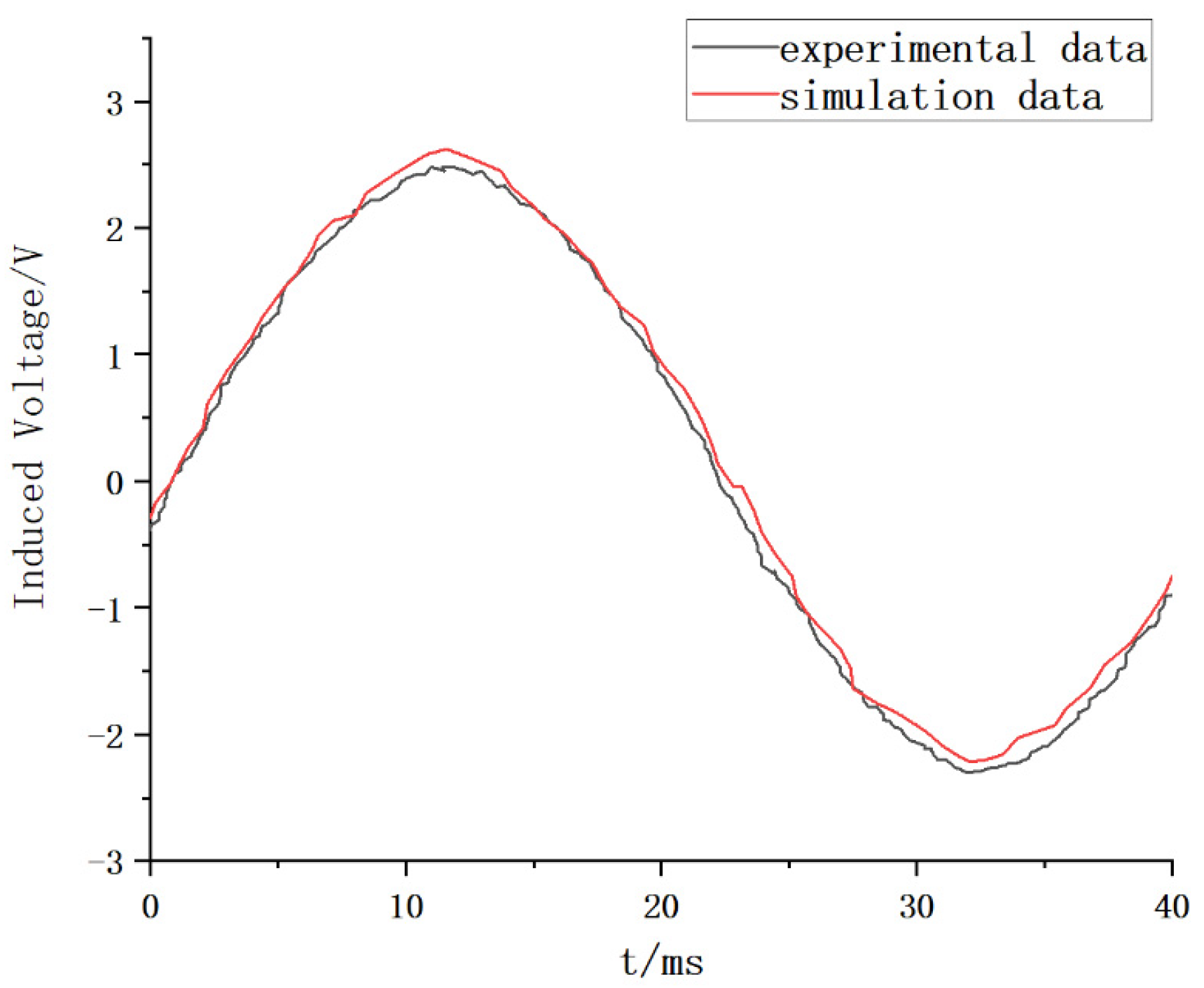
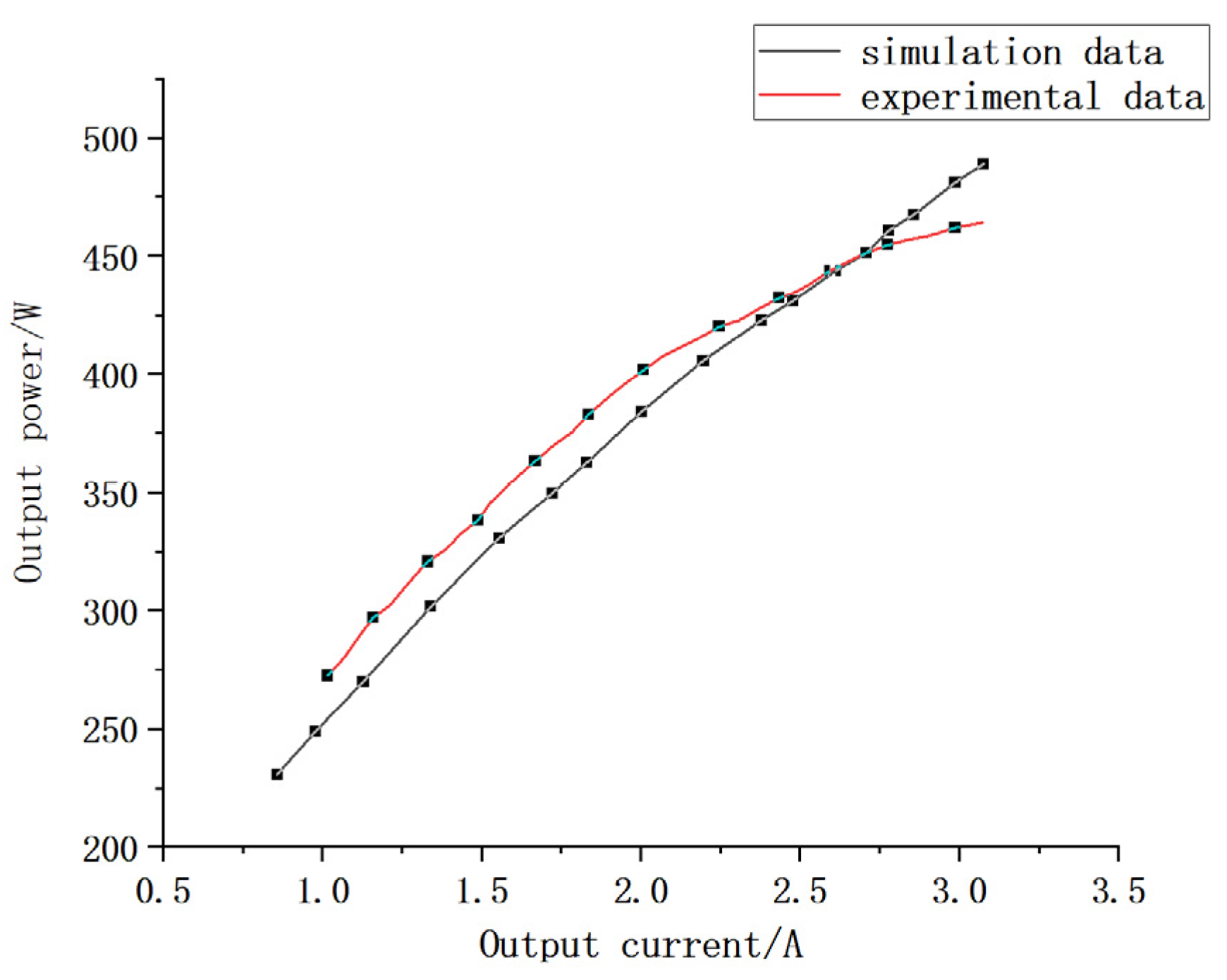
6. Prototype Experiment

The stator coreless disc motor prototype based on PCB winding was manufactured according to the above motor design parameters, as shown in Figure 8, in which (a) is the PCB stator, (b) is the motor rotor, and (c) is the overall model diagram of the prototype. The experimental platform shown in Figure 9 was built for experiments.
In the experiment, a 1.5 kW permanent magnet synchronous motor was used as the prime mover to drag a PCB statorless disc motor running at 750 r/min, and a coupling was used to connect the two. By measuring the three-phase winding phase voltage of the PCB statorless disc motor, the no-load induced voltage waveform of one phase was obtained and compared with the simulation results, as shown in Figure 10.
The simulation results of the no-load induced voltage in the figure are consistent with the actual measurement results. It can be concluded that the optimal design of the motor is reasonable in this paper. The stator winding temperature of the motor was measured over a number of operating hours to obtain the average temperature generated by the motor stator winding, 142 °C, which is 8 °C higher than the simulation results. Thus, a prototype connected to a pure resistive load can be obtained from the motor output power with the output current change pattern shown in Figure 11.
As shown in Figure 11, the value is slightly lower than the simulation results, and the difference between the generated temperature and output power mainly arises from the simulation model ignoring the PCB board over-hole sinking copper onto the motor winding, but it also indirectly proves the effectiveness of the optimization method for the motor in the paper.

7. Conclusions

This article proposed a multi-parameter optimization design algorithm based on an orthogonal response surface for the multi parameter optimization problem of PCB stator coreless disc motors. By using the orthogonal method, the distortion rate of the air gap magnetic density waveform was reduced, and the torque and magnetic density amplitude of the air gap were increased. It was determined that the number of rotor poles of the motor is 8, the ratio of the size of the auxiliary magnetic pole of the permanent magnet to the size of the main magnetic pole is 2, the thickness of the permanent magnet is 3 mm, and the length of the air gap is 1 mm. Then, in order to extend the use time of the PCB board and to reduce the increase in winding temperature generated when the motor was running, BBD experiments were conducted on the motor stator to obtain optimized motor parameters. The thickness of the motor PCB board was determined to be 1.62 mm, the aperture on the board is 0.25 mm, and the uneven width of the stator winding is 0.1 mm. At this time, the motor’s temperature increase can be minimized. The air gap flux density of the motor permanent magnet after optimization is 0.73 T, the distortion rate of the air gap magnetic density waveform is 21.9%, the torque is 182 mN·m, the average temperature is 134 °C, and the eddy current loss is 0.42 W. This verifies the effectiveness of the multi-objective optimization design and provides a new idea for the multi-parameter optimization of PCB stator coreless disc motors in the future.

Author Contributions

Conceptualization, H.S., W.H. and Y.G.; methodology, H.S. and Y.L.; software, H.S., Y.L. and G.L.; validation, H.S., L.Z. and Z.X.; formal analysis, H.S. and Y.L.; investigation, L.Z.; resource, G.L.; data curation, Z.X.; writing—original draft preparation, H.S.; writing—review and editing, Y.L.; visualization, L.Z.; supervision, W.H.; project administration, G.L.; funding acquisition, Y.G. All authors have read and agreed to the published version of the manuscript.

Funding

This work is funded by S&T Program of Hebei (20314501D); Science and Technology Project of Hebei Education Department (ZD2022030); Overseas Expertise Introduction Project of Hebei (2023).

Data Availability Statement

Data available on request due to restrictions eg privacy or ethical. The data presented in this study are available on request from the corresponding author. The data are not publicly available due to the need for follow-up studies.

Conflicts of Interest

The authors declare no conflict of interest.

References

  1. Sultan, H.M. Design and Modeling of a Robust Sensorless Control System for a Linear Permanent Magnet Synchronous Motor. Electronics 2021, 10, 966. [Google Scholar] [CrossRef]
  2. Qiu, R.; Hua, Q.; Zhang, H. Optimization design of permanent magnet synchronous motor rotor based on Taguchi method. J. Qingdao Univ. (Eng. Technol. Ed.) 2020, 35, 57–61. [Google Scholar]
  3. Wang, X.; Huang, X.; Li, T. Optimization design of PCB stator disc permanent magnet motor winding under high-frequency power supply conditions. J. China Electr. Eng. 2021, 41, 1937–1946. [Google Scholar]
  4. Lu, Y.; Li, J.; Qu, R.; Ye, D.; Lu, H.; Sun, J.; Ge, M.; Xu, H. Electromagnetic Force and Vibration Analysis of Permanent-Magnet-Assisted Synchronous Reluctance Machines. IEEE Trans. Ind. Appl. 2018, 54, 4246–4256. [Google Scholar] [CrossRef]
  5. Zhang, W.; Xu, Y.; Zhou, G. Research on a Novel Transverse Flux Permanent Magnet Motor with Hybrid Stator Core and Disk-Type Rotor for Industrial Robot Applications. IEEE Trans. Ind. Electron. 2021, 68, 11223–11233. [Google Scholar] [CrossRef]
  6. Zhang, C.; Chen, Z.; Mei, Q.; Duan, J. Application of Particle Swarm Optimization Combined with Response Surface Methodology to Transverse Flux Permanent Magnet Motor Optimization. IEEE Trans. Magn. 2017, 53, 1–7. [Google Scholar] [CrossRef]
  7. Abdelrahem, M.; Hackl, C.; Kennel, R. Robust Predictive Control Scheme for Permanent-Magnet Synchronous Generators Based Modern Wind Turbines. Electronics 2021, 10, 1596. [Google Scholar] [CrossRef]
  8. Tang, R. Theory and Design of Modern Permanent Magnet Motors; Mechanical Industry Press: Beijing, China, 2016. [Google Scholar]
  9. Ebrahimi, M.; Javadi, H.; Daghigh, A. Maximum power point tracking of a variable speed wind turbine with a coreless AFPM synchronous generator using oTc method. In Proceedings of the 2017 8th Power Electronics, Drive Systems & Technologies Conference (PEDSTC), Mashhad, Iran, 14–16 February 2017; pp. 507–512. [Google Scholar]
  10. Wang, X.; Lou, F.; Li, C. PCB disc type permanent magnet synchronous motor spiral winding optimization. Chin. J. Electr. Eng. 2017, 37, 6092–6100. [Google Scholar]
  11. Wang, X.; Li, H.; Pang, W.; Li, C.-P. Comparative analysis of distributed windings for PCB statorless disc motors. J. Electr. Mach. Control 2018, 22, 11. [Google Scholar]
  12. Ma, Y.; Ching, T.W.; Fu, W.N.; Niu, S. Multi-Objective Optimization of a Direct-Drive Dual-Structure Permanent Magnet Machine. Magn. IEEE Trans. 2019, 55, 1–4. [Google Scholar] [CrossRef]
  13. Silva, A.M.; Antunes, C.H.; Mendes, A.M.; Ferreira, F.J. On Phase Shifting and Diversified Coil-Pitch for Enhanced Multiobjective Winding Design Optimization. IEEE Trans. Energy Convers. 2020, 36, 2002–2011. [Google Scholar] [CrossRef]
  14. Farhan, A.; Johnson, M.; Hanson, K.; Severson, E.L. Design of an ultra-high speed bearingless motor for significant rated power. In Proceedings of the IEEE Energy Conversion Congress and Exposition, Detroit, MI, USA, 11–15 October 2020; IEEE: Piscataway, NJ, USA, 2020. [Google Scholar]
  15. Liu, F.; Wang, P.; Lei, Y. Structural Optimization of Permanent Magnet Vernier Motors Based on Taguchi Method. Exp. Technol. Manag. 2020, 37, 96–100. [Google Scholar]
  16. Zhou, X.; Zhu, X.; Wu, W.; Xiang, Z.; Liu, Y.; Quan, L. Multi-objective optimization design of variable-saliency-ratio PM motor considering driving cycles. IEEE Trans. Ind. Electron. 2020, 68, 6516–6526. [Google Scholar] [CrossRef]
  17. Du, X.; Deng, J. Optimization of Air Gap Magnetic Density Waveform of Permanent Magnet Synchronous Motor Based on GPR-PSO Model. Explos. Proof Mot. 2017, 52, 20. [Google Scholar]
  18. Cao, Y.; Huang, Y.; Jin, L.; Hu, M. Design and analysis of axial magnetic field coreless permanent magnet motors with magnetic pole combination. Chin. J. Electr. Eng. 2014, 34, 903–909. [Google Scholar]
  19. Gao, F.Y.; Qi, X.D.; Li, X.F.; Tao, C.X.; Gao, P. Analytical calculation and optimization analysis of electromagnetic performance of unequal-width unequal-thickness Halbach partially segmented permanent magnet synchronous motor. J. Electrotechnol. 2022, 37, 1398–1414. [Google Scholar]
  20. Wang, X. Design and Analysis of a New Type of Coreless Armature Disc Motor; China Shipbuilding Research Institute: Beijing, China, 2012. [Google Scholar]
  21. Liu, R.; Liu, J.; Zhang, J.; Sun, G. Analytical model of eccentric air gap magnetic field of rotor of Halbach array list-pasted permanent magnet motor based on hyperbolic cotangent transform. J. Electrotechnol. 2023, 38, 1433–1446. [Google Scholar]
  22. Du, X.; Huang, K.; Tan, G.; Huang, X. Multi-objective optimization of permanent magnet motor torque based on response surface method. Micro Spec. Mot. 2019, 47, 20–23. [Google Scholar]
  23. Yang, X.; Ren, Z.; Guo, B.; Ding, Y. Probabilistic optimal energy flow calculation method for electricity-gas interconnection system based on stochastic response surface. New Technol. Electr. Energy 2021, 40, 1–9. [Google Scholar]
  24. Liu, G.; Wang, Y.; Chen, Q.; Xu, G.; Song, C. Multi-Objective Deterministic and Robust Optimization Design of a new Spoke-Type Permanent Magnet Machine for the Improvement of Torque Performance. IEEE Trans. Ind. Electron. 2020, 67, 10202–10212. [Google Scholar] [CrossRef]
Figure 1. Schematic diagram of motor structure.
Electronics 12 03020 g001
Figure 2. Permanent magnet arrangement.
Electronics 12 03020 g002
Figure 3. Eddy current loss response surface model.
Electronics 12 03020 g003
Figure 4. Average temperature response surface model.
Electronics 12 03020 g004
Figure 5. Torque response surface model.
Electronics 12 03020 g005
Figure 6. Motor stator winding; PCB board; over-hole diagram.
Electronics 12 03020 g006
Figure 7. Comparison of motor performance before and after optimization.
Electronics 12 03020 g007
Figure 8. Photos of the experimental prototype of the motor: (a) PCB Stator; (b) rotor; (c) motor assembly.
Electronics 12 03020 g008
Figure 9. Prototype experiment platform.
Electronics 12 03020 g009
Figure 10. No-load induced voltage waveform simulation results compared with the measured.
Electronics 12 03020 g010
Figure 11. Output power curve of the prototype.
Electronics 12 03020 g011
Table 1. Basic parameters of the finite element model of the motor.
ParameterNumerical Value
Rated power, w500
Rated speed, r/min750
Outer diameter of stator, mm100
Stator bore, mm70
Number of PCB coils per layer3
Coil conductor thickness, mm0.105
Width of coil conductor, mm0.70
Insulation distance between conductors, mm0.20
Number of coil conductor layers12
PCB Number of sections1
Table 2. Initial Design Factors.
Initial Design FactorHorizontalNumerical Value
Number of rotor poles p12
24
36
48
Main/auxiliary magnetic pole size ratio Rnd10.5
21
32
43
Permanent magnet thickness Tm, mm13
24
35
46
Air gap length δ, mm10.5
20.8
31
41.2
Table 3. Average values of various factors at various performance levels.
DivisorHorizontalTd, mN·mBδ, TTHD, %
A193.30.4338.0
242.80.5642.4
374.40.6035.6
481.70.6628.2
B148.10.5654.5
277.90.5842.2
3111.70.5725.3
454.30.5422.1
C1100.00.5326.5
265.20.5339.2
392.10.6039.9
434.80.6138.6
D158.40.6160.3
280.70.5539.5
390.00.5236.8
463.00.5838.3
Table 4. BBD experimental design and simulation results.
Order NumberPlate
Thickness,
mm
Aperture,
mm
Unequal Width,
mm
ABCEddy
Current Loss,
W
Average Temperature,
°C
Torque,
mN·m
11.40.150.15−1−100.436127.1161
21.80.150.151−100.428130.0112
31.40.250.15−1100.432129.7164
41.80.250.151100.423107.4117
51.40.200.10−10−10.425158.4192
61.80.200.1010−10.415134.4136
71.40.200.20−1010.443118.6177
81.80.200.201010.434106.3129
91.60.150.100−1−10.424140.4181
101.60.250.1001−10.418136.8184
111.60.150.200−110.432119.2176
121.60.250.200110.43097.2179
131.40.150.10−1−1−10.429162.7182
141.60.200.150000.434130.9160
151.80.250.201110.433102.4131
Table 5. Motor parameter values before and after optimization.
Motor ParametersBefore OptimizationAfter Optimization
Number of rotor poles48
Primary/auxiliary pole size ratio12
Thickness of permanent magnets5 mm3 mm
Air gap length0.8 mm1 mm
Plate thickness1.4 mm1.62 mm
Aperture0.1 mm0.25 mm
Unequal width0.2 mm0.1 mm
Disclaimer/Publisher’s Note: The statements, opinions and data contained in all publications are solely those of the individual author(s) and contributor(s) and not of MDPI and/or the editor(s). MDPI and/or the editor(s) disclaim responsibility for any injury to people or property resulting from any ideas, methods, instructions or products referred to in the content.

