Article

New Methodology for Parasitic Resistance Extraction and Capacitance Correction in RF AlGaN/GaN High Electron Mobility Transistors

1
Department of Electrical, Electronic and Computer Engineering, University of Ulsan, Ulsan 44610, Republic of Korea
2
Department of Semiconductor Processing Equipment, Semiconductor Convergence Campus of Korea Polytechnics, Anseong-si 17550, Republic of Korea
*
Authors to whom correspondence should be addressed.
Electronics 2023, 12(14), 3044; https://doi.org/10.3390/electronics12143044
Submission received: 19 June 2023 / Revised: 6 July 2023 / Accepted: 10 July 2023 / Published: 11 July 2023
(This article belongs to the Section Semiconductor Devices)

Abstract

:
This paper presents a novel approach to the efficient extraction of parasitic resistances in high electron mobility transistors (HEMTs). The study reveals that the gate resistance value can be accurately determined under specific forward gate bias conditions (Vg = 1.0 V), although the gate resistance value becomes unreliable beyond this threshold (Vg > 1.0 V) due to potential damage to the Schottky contact. Furthermore, by examining the characteristics of the device under a cold-FET bias condition (Vds = 0 V), a linear correlation between the gate and drain current is identified, enabling an estimation of the interdependence between the drain and source resistance using the proposed method. The estimation of parasitic pad capacitance (Cpg and Cpd) from Dambrine’s model is refined by incorporating the depletion layer capacitance on the gate side during the pinch-off condition. To validate the accuracy of the extracted parasitic capacitance and resistance values obtained from the new method, small-signal modeling is performed on a diverse range of measured devices.

1. Introduction

Gallium nitride high electron mobility transistors (GaN HEMTs) have been extensively applied in microwave and millimeter-wave power amplifiers due to their high-power density and high-frequency features, making them suitable for applications such as communication, radar, and satellites [1,2,3,4]. Even without doping, the AlGaN/GaN heterostructure’s large conduction band discontinuity (which is related to the difference in electron affinities between the two materials), combined with large piezoelectric and spontaneous polarization effects, result in the formation of an extremely high-density two-dimensional electron gas (2DEG) [5,6]. The high density of 2D electron gas (2-DEG), caused by strong spontaneous and piezoelectric polarization, results in the normal ON operation of AlGaN/GaN HEMTs. However, this operational mode is not suitable for power electronic applications due to safety and system cost considerations. The utilization of GaN-based HFETs shows significant promise in radio-frequency (RF) power and switching applications. The continuous advancements in semiconductor epitaxy, device processing, and system integration have led to the emergence of an industrial supply chain specifically for GaN power devices. It is widely assumed that an appropriate extraction technique for a robust small-signal equivalent circuit is critical for circuit design, process technology assessment, and device performance optimization [7,8]. Such small-signal modeling should encompass a circuit-level description of the device’s nonlinear properties. Small-signal equivalent circuit modeling plays a crucial role in gaining valuable insights into device nonlinearity, particularly in the static sense, when conducted under different bias conditions. It is evident that the accuracy of the small-signal extraction method employed directly impacts the validity of the device modeling.
The important characteristics of AlGaN/GaN HEMTs are high sheet carrier density (ns >> 1  ×  1013 cm−2) that produces high Imax, mobility of electron is high ( μ >  1500 cm2/Vs) which suitable for low on-resistance (Ron), high breakdown voltage and high operating channel temperature [9,10,11]. Several groups have investigated the high-performance DC analysis of AlGaN/GaN HEMTs [12,13]. Nonetheless, the theoretical studies of AlGaN/GaN transistor at high temperatures are not developed fully. Ensuring accurate measurements of S-parameters is crucial for determining realistic equivalent circuit parameters. Only with accurate S-parameter measurements can the extracted values hold meaningful physical significance. The accurate characterization of S-parameters serves as a foundation for obtaining reliable and meaningful equivalent circuit parameters.
Moreover, for accurate small-signal models, accurate extraction of parasitic resistances, capacitances, and inductances is required, which affects the whole RF characteristics of the devices. To element the effect of the parasitic components from the DUT, several methods have been discussed in the literature, such as open-short, two-step, and three-step de-embedding techniques [14,15,16,17]. At the beginning, the conventional de-embedding method was used to determine the Y-parameters, but it was only counting the capacitances act as a open circuit ignoring the effect of inductance present in the circuit. Koolen et al. [18], described the efficient analysis of determining parasitic components by considering impedance (Z) which induced in the circuit. They developed the model both considering ‘open’ interconnect pattern (Yopen) as well as ‘short’ pattern (Yshort) to determine the parasitic admittance. This method is still used in the industry for eliminating parasitic components. However, this method’s limitation is to use test dummy pattern which reduces accuracy in high frequencies.
Two step de-embedding [19] method required different calibration types such as SOLT (Short, Open, Load, Thru), TRL (Thru, Reflect, Line) and TRM (Thru, Reflect, Match) chosen to determine accuracy. This method uses only two dummy structures, Pad-Open and a complete short. The Pad-open dummy pattern uses to remove pad parallel impedance and the second one is for removing the series impedance of the interconnection between the line and the DUT (device under test). However, the problem is imperfection of dummy can cause inaccurate calculation of the parasitic components.
In the case of bipolar junction transistor (BJT), more accurate interpretation of S-parameter measurements by employing a three-step de-embedding procedure [16,17]. This procedure involves subtracting the y-parameters of the open circuit, as well as subtracting the z-parameters obtained from on-wafer shorts and through measurements of the Device Under Test (DUT). By considering the physical origins of y- and z-parameters, this three-step approach offers a more desirable solution for achieving accurate results. The steps include subtracting the on-wafer open y-parameters that affect the input and output ports, followed by subtracting the on-wafer z-parameters. This de-embedding technique requires four patterns such as open, thru, short1 and short2. While the three-step de-embedding methods mentioned earlier offer improved characterization of pad contacts in the measurement structure, they have limitations when it comes to achieving high accuracy in the millimeter-wave frequency range. This is mainly due to their reliance on a lumped-parameter interconnection model, which becomes less accurate in higher frequencies. Therefore, these methods are not able to provide the desired level of accuracy when dealing with millimeter-wave frequencies. With the increasing operation frequency of transistors reaching the sub-millimeter-wave range, the complexities of parasitic electromagnetic coupling effects also intensify. Therefore, the accuracy of the three-step de-embedding method, which involves the use of three de-embedding dummies, may be insufficient.
As transistors continue to shrink in size from micrometer to nanometer scale and operating frequencies reach the Terahertz range, the impact of open/short port effects and substrate coupling between input and output pads becomes more pronounced. These effects are not adequately addressed in the previously mentioned method. To enhance the accuracy of de-embedding, additional measurements involving a dummy structure are incorporated into the conventional open-short method.
Extensive research has been conducted to enhance the de-embedding accuracy specifically in the submillimeter-wave range. As a result, multistep de-embedding methods have been explored and developed. These methods aim to provide improved accuracy by incorporating additional steps and techniques to account for the complexities introduced by higher frequencies. Among the various multistep de-embedding methods, four-step de-embedding approaches have gained popularity in addressing the accuracy challenges in the submillimeter-wave range. Examples of these methods include open-short-open-short [20,21], open-open-thru-short [22], through-reflect-line-short [23]. These techniques involve additional steps and measurements to improve the accuracy of de-embedding at higher frequencies. Exploring additional de-embedding standards allows for the consideration of more parasitic parameters. However, as the number of measurement standards increases, the error resulting from measurement uncertainty also tends to rise. This presents a significant challenge in achieving accurate measurements. The trade-off between incorporating more standards to account for additional parasitic parameters and managing the accompanying increase in measurement uncertainty poses a difficult task. In general, the de-embedding methods discussed so far are based on measurements. This means that the de-embedding process is directly implemented using the measured data from the de-embedding structure’s matrix substrate. Nevertheless, these methods exhibit a tradeoff between the complexity of the de-embedding structures and the accuracy of de-embedding, particularly in the high-frequency range. As the complexity of the de-embedding structure increases, it may lead to improved accuracy. However, striking the right balance between complexity and accuracy becomes crucial to ensure practical and reliable de-embedding results at high frequencies.
However, all the parasitic components are not extracted efficiently using those methods. The most convenient method for extracting parasitic components is known as the cold-FET de-embedding technique [1,3,8,24,25,26], where all the parasitic components can be extracted from the cold-FET in various biases. The cold-FET de-embedding technique is a convenient and effective method for extracting parasitic components in semiconductor devices. This technique utilizes a “cold” or non-conducting FET (Field-Effect Transistor) as a reference device to characterize and eliminate the effects of parasitic elements present in the measurement setup [8]. The extracted parasitic components obtained from the cold-FET de-embedding technique provide crucial insights into the device’s performance and aid in developing accurate equivalent circuit models. These models can then be utilized for further analysis, optimization, and design of high-frequency devices and circuits. In contrast, the resistance extraction method also has some drawbacks in the research field, because bias dependency of the resistances is overlooked. Although resistances are frequency independent, they are eventually bias dependent. The well-known equation for resistance extraction contains three basic equations constructed through Z-parameters with four unknown variables [8,27]. Hence, another equation or relationship is required to determine the values of the unknown parameters. Although there are various straightforward research methods for building an additional relationship, none of them are clearly evaluated. To overcome these difficulties, we propose a new method of resistance extraction focusing on an additional equation, which can be applied to determine the unknown variables more conveniently. The aim of this paper is to illustrate this unique method and capacitance correction. In Section 2, materials information and a detailed analysis of the resistance extraction technique are presented. The overall experimental results and discussion are presented in Section 3, and the conclusions are presented in Section 4.

2. Materials and Measurement of the Equivalent Circuit

2.1. Fabrication

The epitaxial layer structures were grown using low-pressure metal-organic chemical vapor deposition (MOCVD) technique on 3-inch SiC wafers. This epitaxial structure consisted of an Al0.45Ga0.55N barrier (8 nm), a Ga-polarity GaN channel layer (420 nm), and a GaN buffer layer (270 nm) on top of the SiC substrate (Figure 1a). The device fabrication involved mesa isolation etching, source/drain ohmic contact formation and gate patterning. The mesa isolation etching was performed using a reactive ion etching (RIE) system. Subsequently, the ohmic contacts were formed by standard Ti/Al/Ni/Au (25/160/40/100 nm) metallization on the source and drain regions, followed by rapid thermal annealing (RTA) at 830 °C for 30 s in an N2 ambient to allow the formation of contacts on the AlGaN/GaN epi-structure. Metallization was performed via the lift-off technique. The Schottky gate contacts were then patterned by photolithography. The Ni/Au (20/300 nm) and Pt/Ti/Pt/Au (8/20/20/300 nm) Schottky gate contacts were fabricated by e-beam evaporation, and Al2O3 (3 nm) was deposited as the surface passivation layer. The real device picture showed in (Figure 2b) which is used for the experiment. The basic construction of the device includes two source pad, gate and drain pad with two fingers. Measurements of the current leakage characteristics (I–V) and gate leakage characteristics (Ig–Vg) were evaluated using a Keithley 4200SC semiconductor parameter analyzer and RF measurements were performed by an 8510C Network analyzer.

2.2. Problem Statement

We studied the equivalent circuit topology that was used for the determination of intrinsic elements gm, gd, Cgs, Cgd, Cds, Ri, Rds, and τ which shown in Figure 1c. Additionally, the extrinsic elements were cpg, cpd, cpgd, Rg, Rs, Rd, Lg.pad, Ld.pad, Ls, Lg_ex_line, and Ld_ex_line. We included line inductance in our reference circuit to obtain better accuracy. We mainly focused on the extraction of parasitic components, which is why the intrinsic elements extraction process is not covered in this paper. At high frequencies, the effect of parasitic capacitances is negligible, while the effects of resistances and inductances are introduced and considered. Under a cold bias condition (Vds = 0 V), the basic equation for resistance extraction can be written as follows:
R s + R g + R c h 3 = Re ( Z 11 )
R s + R c h 2 = Re ( Z 12 )
R d + R g + R c h = Re ( Z 22 )
These three equations are constructed with four unknown variables. Most of the existing research methodologies use approximations to determine the fourth unknown variable or the high-frequency channel resistance value is ignored. Lu et al. [28] obtained the value of Rs + Rd under a cold-pinched off (Vgs < Vth, Vds = 0 V) condition. However, there was no maximum or minimum limit included for the Vgs pinch-off condition and the process of extraction was not stated clearly. Dambrine et al. [8] postulated four conditions about the extraction of another unknown variable, which included the conventional method [29]. In their method, the series resistance (Rs) calculation in the DC method always provided higher values. This would be questionable and possibly problematic when calculating the channel resistance from Equation (2). There was also a difference between the DC method and the RF method for resistance extraction. Therefore, the fluctuation of the resistance values is inevitable, resulting in incorrect results. In order to overcome these difficulties and the unstable behavior of resistances, we propose a new method for building the relationship between drain and source resistances that can be expressed with one additional equation.

2.3. New Method of Resistance Extraction

At the cold-FET condition (Vds = 0 V), the drain current (Id) does not theoretically flow. However, a small fraction of Id can flow practically, which is visible from the measured RF data. In this case, the drain current does not discernably change the potential distribution inside the channel and the superposition principle is applied to obtain the drain to source voltage [30], as follows:
V d s = ( R s + R d + R c h ) I d + R s + R c h 2 I g
I g I d = ( R s + R d + R c h ) R s + R c h 2
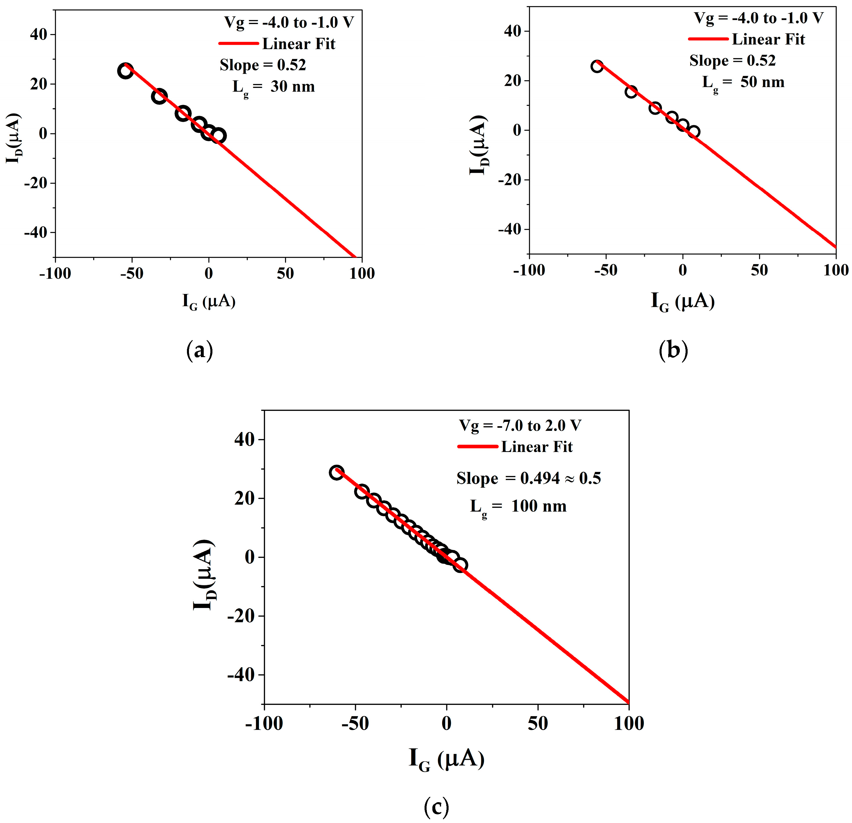
We selected AlGaN/GaN HEMT for measurement, adopting a fixed gate width, Wg = 25 and 50 μm, Lsd = 2 μm, and Lg = 30, 70, and 100 nm. The measurement frequency ranges were from 450 MHz to 50 GHz, with a step of 200 MHz. The bias points started from Vg = −7.0 V, and then increased to +2.0 V in 1 V steps. The dependency between Ig and Id for three gate-length devices, displayed in Figure 2, reveals a linear relationship. Here, the gate current (Ig) is considered an independent variable (x axis), and the drain current (Id) is maintained as a dependent variable (y axis). The slope of the linear fitting provides the value of Ig/Id, which was approximately 0.5 in all the gate-length devices. Substituting the value of the Ig/Id into Equation (5), we can obtain another equation, as follows:
R d 2 R s
The drain resistance (Rd) is almost double the source resistance (Rs).

3. Results and Discussion

3.1. Resistance Extraction from Cold-FET

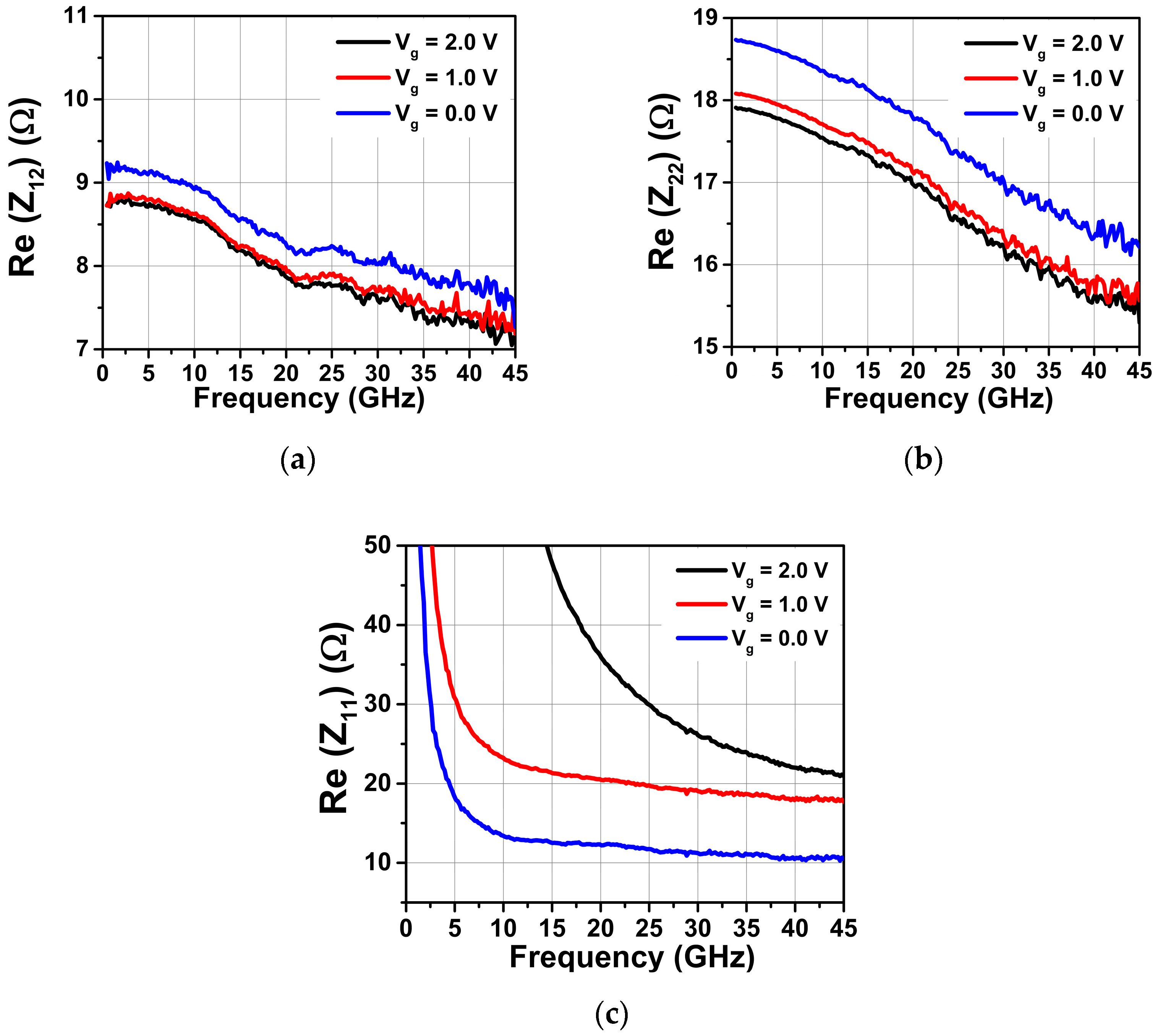
The bias dependencies of the resistances (Rs, Rd, Rg) are clearly visible in Figure 3a–c, respectively. From Figure 3c, it is evident that for Vgs = 0.0 V at high frequencies (>40 GHz), the gate resistance value was approximately 11 Ω. After increasing the bias (Vgs > 0.0 V), the value of the gate resistance (Rg) at high frequencies was not constant. Depending on the bias condition, Rg was found to be 20 and 25 Ω for higher gate voltages (Vg) of 1.0 and 2.0 V, respectively. This variation in resistance at different gate biases was quite narrow for series resistance (Rs) and drain resistance (Rd). At high frequencies, the values of Rs and Rd were acceptable (on average). We also investigated the parasitic resistance calculation in the Lg = 100 nm device according to our new proposed method. The calculated results are displayed in Table 1, Table 2 and Table 3 for the different bias conditions, where almost the same results were measured at Vg = 0.0 V and Vg = 1.0 V, with little variation. This bias region could be considered a stable position for all the calculated resistances.
For the higher forward gate bias, the electron velocity in the short-gate structures started to saturate, increasing the gate resistance [31].

3.2. Parasitic Capacitance Extraction by Dambrine’s Model

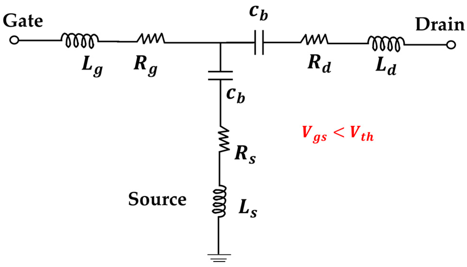
The parasitic capacitances cpd and cpg, shown in the small-signal equivalent circuit (Figure 1), can be extracted by the cold-FET de-embedding method below the pinch-off condition. At the pinch-off condition (Vgs <Vth), the FET equivalent circuit can be expressed by Figure 4. According to Dambrine’s FET model in the pinch-off region, the parasitic capacitance equations can be written as follows:
Im a g ( Y 11 ) = j ω C p g + 2 C b
Im a g ( Y 12 ) = Im a g ( Y 21 ) = j ω C b
Im a g ( Y 22 ) = j ω C p d + C b
where Cb is the depletion layer capacitance in the source and drain sides.
From Dambrine’s cold-FET circuit equation, if the imaginary admittance Imag(Y11) = Imag(Y22), we obtain the following expression:
C p g + 2 C b = C p d + C b
C p d = C p g + C b
which results in pad capacitances not being equal from the circuit perspective. We determined that the pad capacitances were as follows: Cpd = 16.7 fF, Cpg = 0.88 fF, and Cb = 15 fF. These values exhibited a huge discrepancy in the symmetrical structure for HEMTs. Moreover, this model overestimated the cpd pad capacitance. The reason for this result was that there was no given limit of parasitic capacitance extraction at the pinch-off region. We modified the circuit in a way that considered the depletion layer capacitance added in the gate region, as displayed in Figure 5.
Adding the depletion layer capacitances in the pinch-off circuit condition, we can rewrite the modified equations as follows:
Im a g ( Y 11 ) = j ω C p g + C b
Im a g ( Y 12 ) = Im a g ( Y 21 ) = j ω C b
Im a g ( Y 22 ) = j ω C p d + C b
Furthermore, imposing the same condition of Imag(Y11) = Imag(Y22), we revealed that Cpd = Cpg.
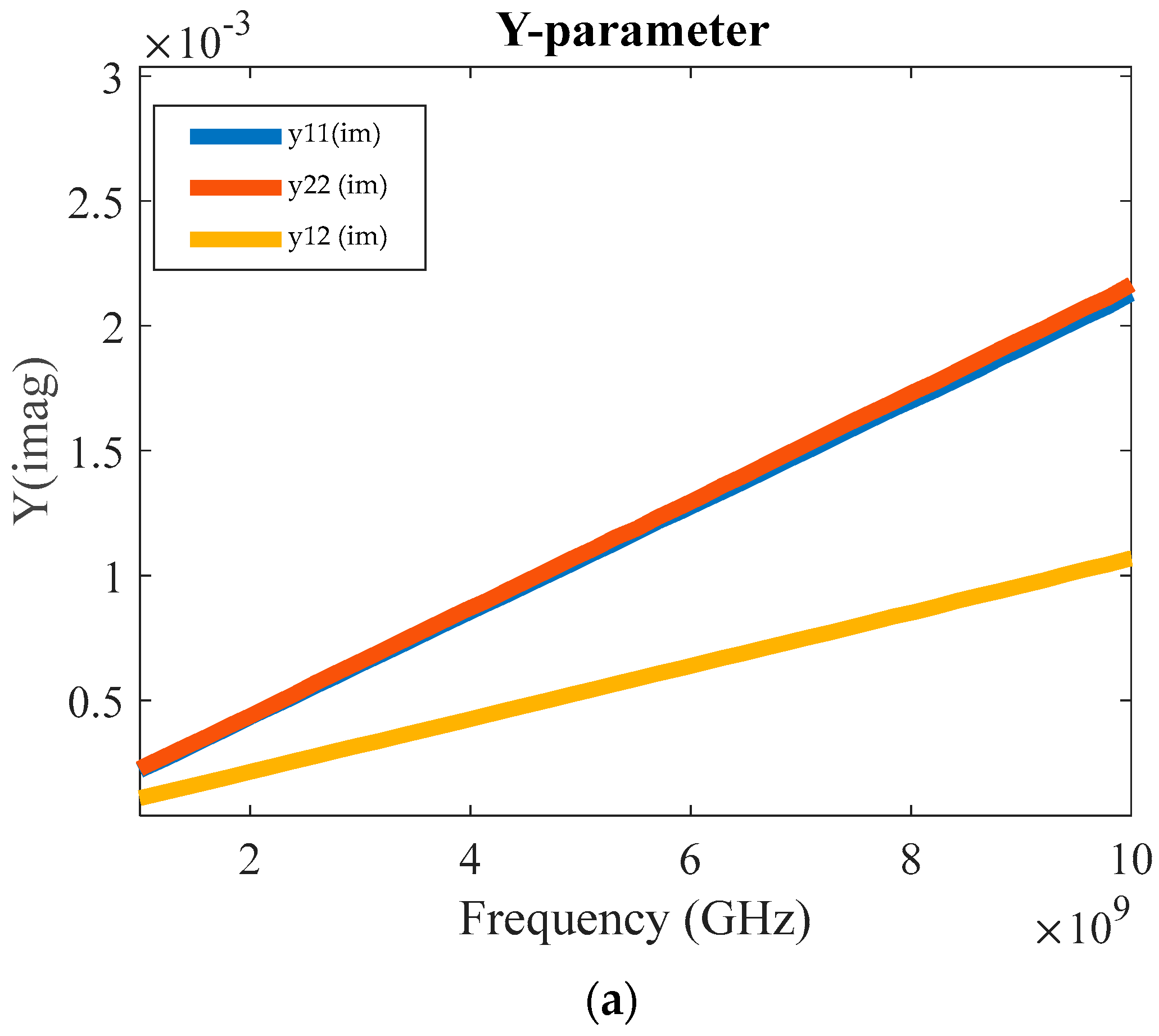
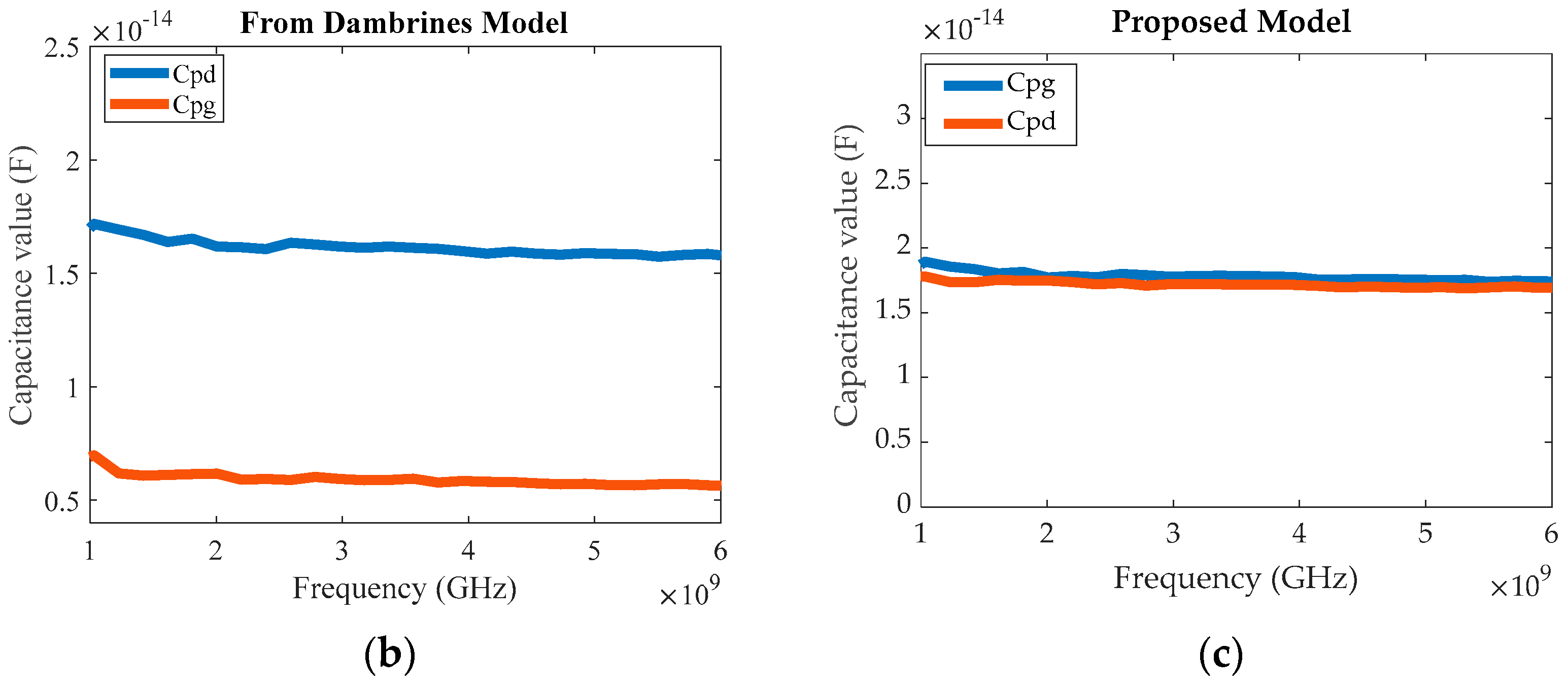
Figure 6a displays the Y-parameter dependency according to frequency. The parasitic capacitance extraction from MATLAB depicted in Figure 6b indicates that the values for Cpd in Dambrine’s model were overestimated. Applying our corrected method, we estimated the pad capacitances as Cpd = 1.19 fF, Cpg = 0.58 fF, and Cb = 15.2 fF, as shown in Figure 6c. All the capacitance values are provided in Table 4 for easier comparison.
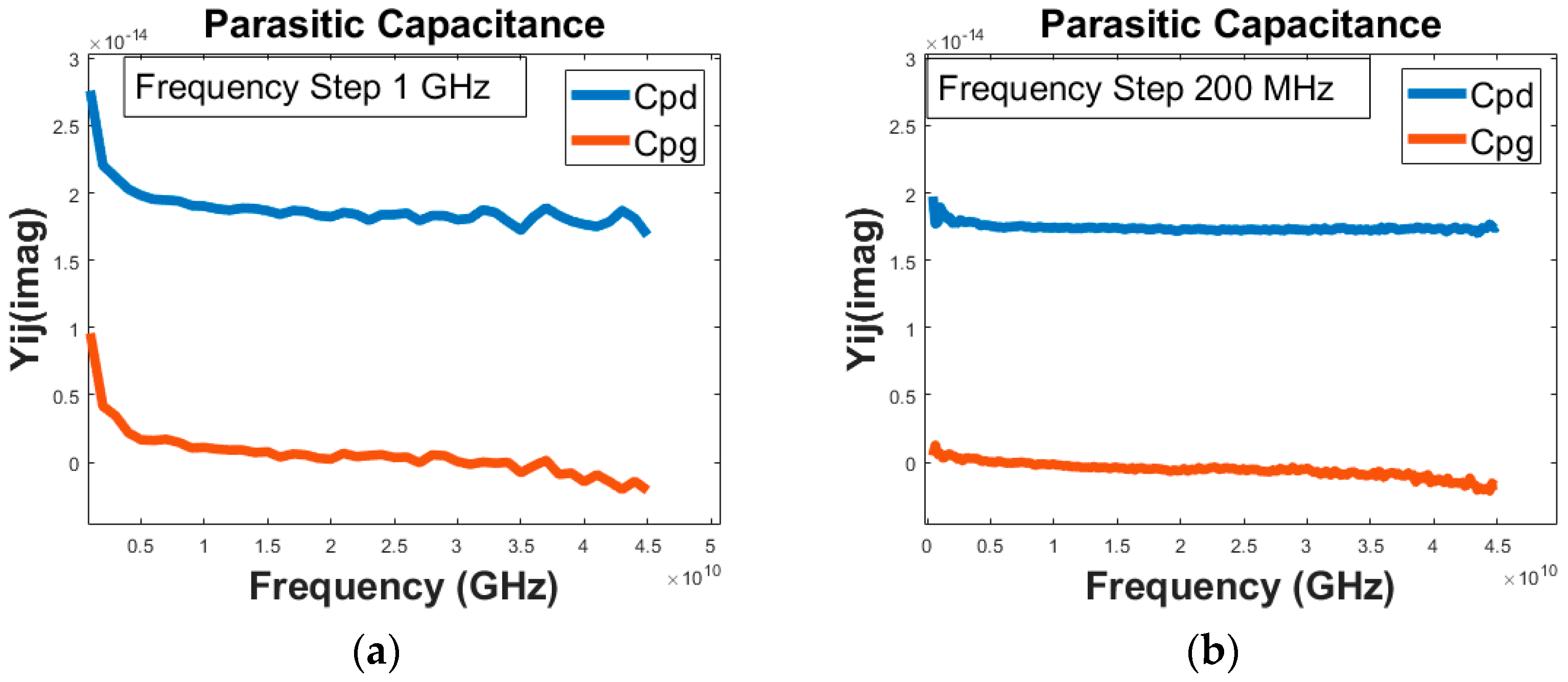
The important thing to be considered for measuring capacitance is step size. If the step size is high enough (>1 GHz), then there will be difficulty calculating pad capacitance. Figure 7a shows that the large step size around 1 GHz creates difficulties in the calculation of pad capacitances. Those values fluctuate high enough when the frequency range increases. After reducing the step size in the measurement process to about 200 MHz, the values in the low-frequency range (<5 GHz) shown in Figure 7b become suitable.
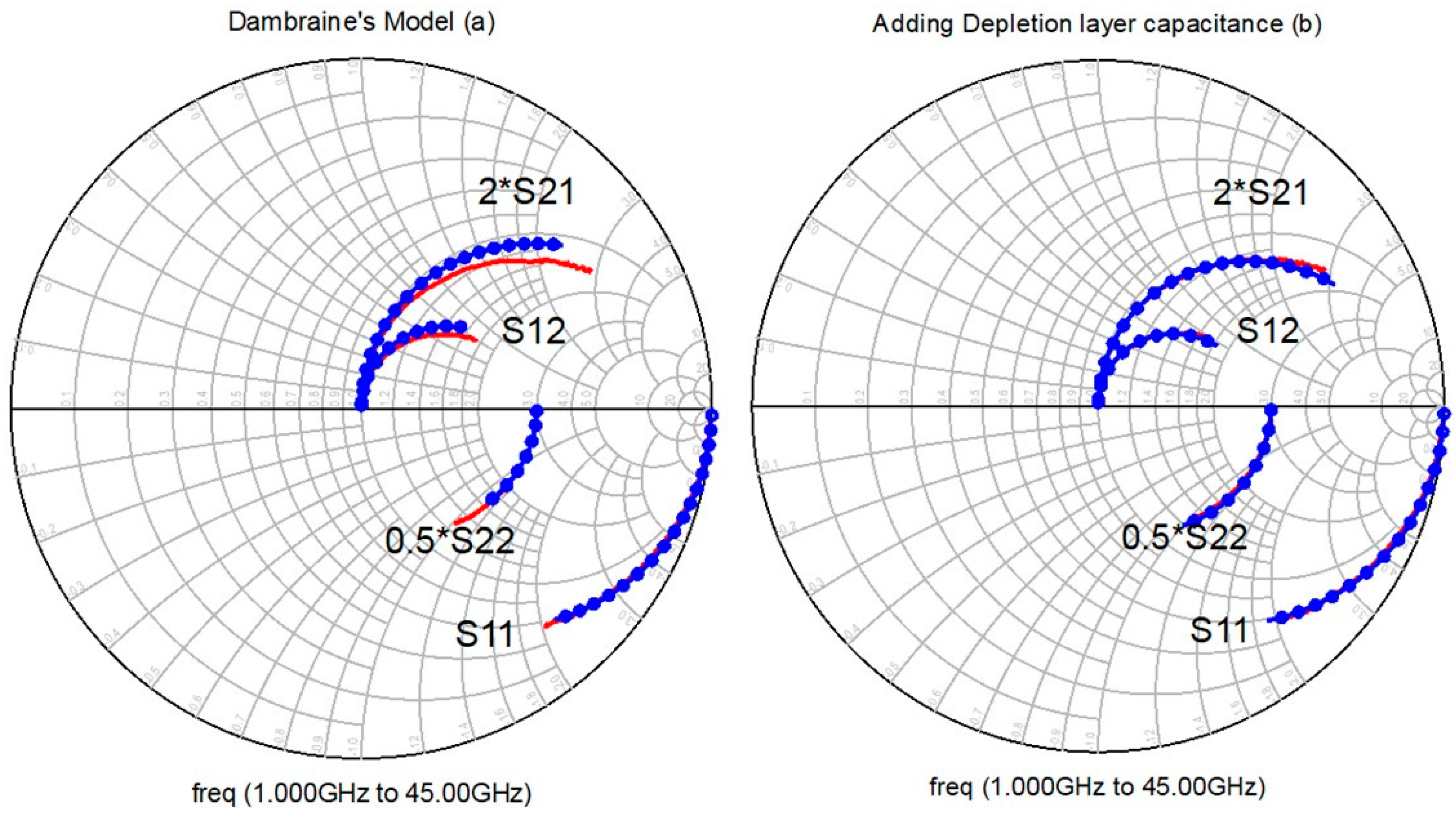
We simulated the small-signal equivalent circuit model in the ADS 2020 software to provide a comparison between our method and Dambrine’s circuit model. The difference prior to the addition of the depletion layer capacitance is displayed in Figure 8a. The measurement (red line) and modeled (blue close circle) results were perfectly matched after adding capacitance and resistance, as depicted in Figure 8b.

3.3. Model and Measurement Data Validation

We used measured data from ICCAP and modeled the results in ADS software to compare the result with our proposed method. For calculations of the inductance, the Z-parameters can be written as [32]
Z 11 = R g + R s + j ω ( L g + L s ) + 1 j ω 1 C g + 1 C s
Z 22 = R d + R s + j ω ( L d + L s ) + 1 j ω 1 C d + 1 C s
Z 22 = R s + j ω L s + 1 j ω C s
Multiplying the Z-parameters with  ω  and considering the imaginary terms results
Im [ ω Z 11 ] = ω 2 ( L g + L s ) 1 C g + 1 C s
Im [ Z 22 ] = ω 2 ( L d + L s ) 1 C d + 1 C s
Im [ Z 22 ] = ω 2 L s 1 C s
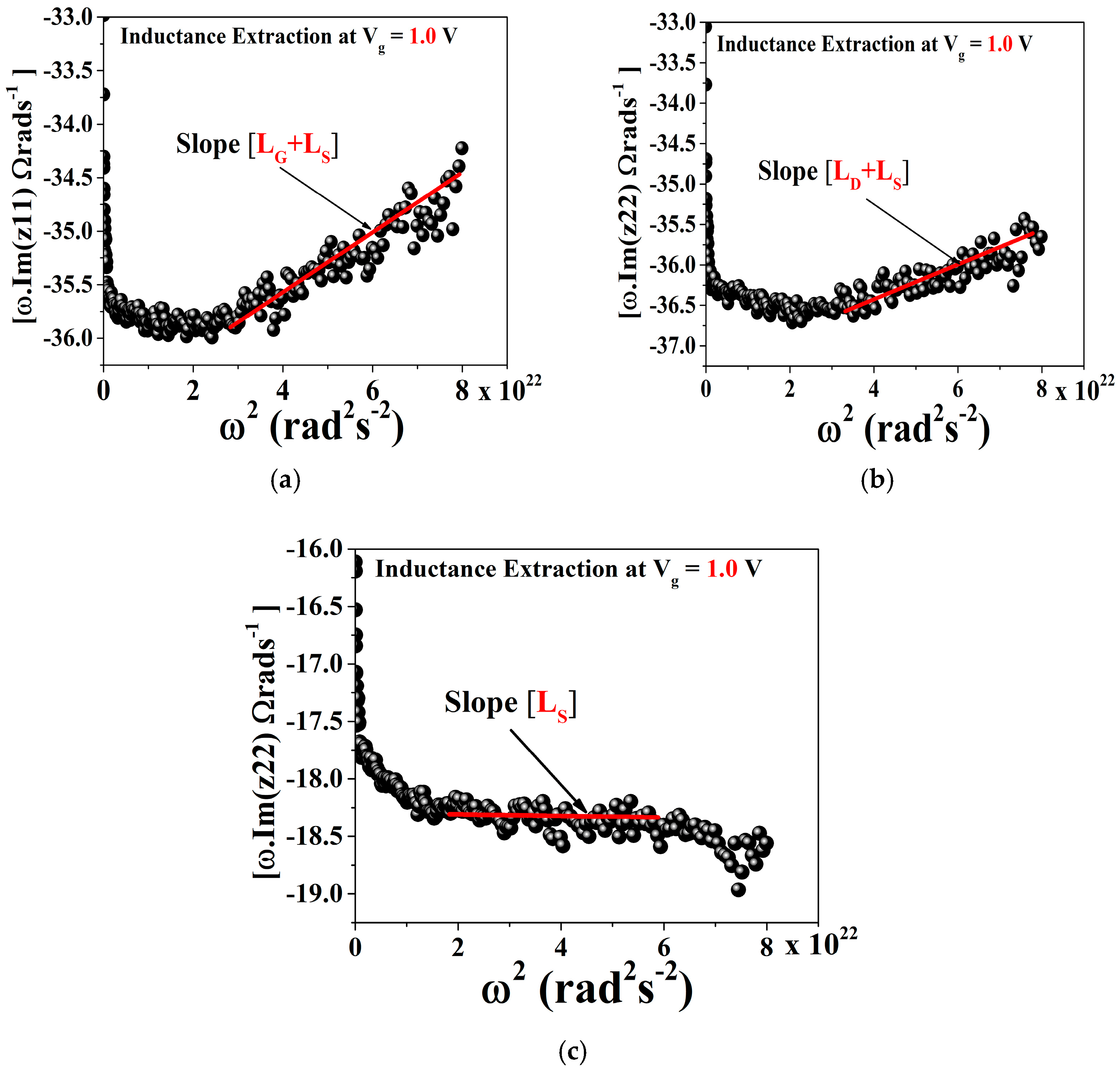
Therefore, Lg, Ld, Ls can be extracted from the slope of Equations (18)–(20), respectively. The inductance values were extracted from forward gate bias condition Vg = 1.0 V using the least-square-regression method shown in Figure 9.
Figure 10 displays a comparison of the modeled and measurement results for two different gate widths (Wg = 2  ×   25   μ m  and Wg = 2  ×   50   μ m ) and devices with the same gate length Lg = 100 nm. All the values extracted (intrinsic and extrinsic part) from the small-signal model are listed in Table 5. Figure 10a displays the results of 2  ×   25   μ m  devices. This indicated that, due to incorrect values of drain resistance (Rd), source resistance (Rs), and gate resistance (Rg), the measured data did not correlate with the modeled data. After correcting the capacitance and resistance values, the modeled data accurately matched the measured values. Another device (2  ×   50   μ m ) displayed the same results (Figure 10c,d). Figure 10c presents the data where the resistance values are only taken in the high-frequency range, which creates the problem of matching the S22 parameter due to over-estimating the values of the series (Rs) and drain (Rd) resistances. In the high-frequency range, the values obtained were Rs = 7.2 Ω (average) and Rd = 16.5 Ω. Considering that the channel resistance (Rch) was completely eliminated, this completely overestimated the results found in 2  ×   50   μ m    device. In our method, we found that channel resistance still dominated in the high-frequency range. We investigated more than 10 bias points in different gate-length devices (30, 50, 70, 100, and 150 nm), and these results were consistent with our hypothesis.

4. Conclusions

In this paper, we proposed a new method of resistance extraction using a cold-FET circuit and developed a direct extraction method for high-frequency applications of AlGaN/GaN HEMTs. Previous studies have suggested that resistance is an extrinsic element that is not bias-dependent. However, our measurement and data analysis results indicated that the gate resistance (Rg) primarily depends on bias compared to the drain (Rd) and source resistances (Rs). Parasitic capacitance extraction from Dambrine’s model overestimates the Cpd values because it does not remove the depletion layer capacitance in the gate-side region. After adding depletion layer capacitance, the small-signal equivalent circuit exhibited more accurate modeling results with the measurement data.

Author Contributions

T.-W.K. and S.C. developed the main concept of this work. S.C. wrote the original manuscript, including figures, data analysis and overall characterizations. W.A. helped in the measurement. H.-M.K. supervised and reviewed the manuscript. T.-W.K. supervised the entire process. All authors analyzed and discussed the results. All authors have read and agreed to the published version of the manuscript.

Funding

This work was supported by a National Research Foundation of Korea (NRF) grant funded by the Korean government (NRF-2019M3F5A1A0107697322).

Data Availability Statement

The data presented in this study are available on request from the corresponding author.

Conflicts of Interest

The authors declare no conflict of interest.

References

  1. Mishra, U.K.; Shen, L.; Kazior, T.E.; Wu, Y.F. GaN-based RF power devices and amplifiers. Proc. IEEE 2008, 96, 287–305. [Google Scholar] [CrossRef]
  2. Chakraborty, S.; Kim, T.W. Investigation of mean-time-to-failure measurements from AlGaN/GaN high-electron-mobility transistors using Eyring model. Electronics 2021, 10, 3052. [Google Scholar] [CrossRef]
  3. Chakraborty, S.; Kim, T.W. Comprehensive Schottky Barrier Height Behavior and Reliability Instability with Ni/Au and Pt/Ti/Pt/Au on AlGaN/GaN High-Electron-Mobility Transistors. Micromachines 2022, 13, 84. [Google Scholar] [CrossRef] [PubMed]
  4. Amir, W.; Shin, J.W.; Shin, K.Y.; Kim, J.M.; Cho, C.Y.; Park, K.H.; Hoshi, T.; Tsutsumi, T.; Sugiyama, H.; Matsuzaki, H.; et al. A quantitative approach for trap analysis between Al0.25Ga0.75N and GaN in high electron mobility transistors. Sci. Rep. 2021, 11, 22401. [Google Scholar] [CrossRef]
  5. Chakraborty, S.; Amir, W.; Shin, J.W.; Shin, K.Y.; Cho, C.Y.; Kim, J.M.; Hoshi, T.; Tsutsumi, T.; Sugiyama, H.; Matsuzaki, H.; et al. Explicit Thermal Resistance Model of Self-Heating Effects of AlGaN/GaN HEMTs with Linear and Non-Linear Thermal Conductivity. Materials 2022, 15, 8415. [Google Scholar] [CrossRef] [PubMed]
  6. Shin, K.-Y.; Shin, J.-W.; Chakraborty, S.; Amir, W.; Shin, C.-S.; Kim, T.-W. Trap Behavior of Metamorphic HEMTs with Pulsed IV and 1/f Noise Measurement. In Proceedings of the ESSDERC 2022—IEEE 52nd European Solid-State Device Research Conference (ESSDERC), Milan, Italy, 19–22 September 2022; pp. 324–327. [Google Scholar] [CrossRef]
  7. Caddemi, A.; Crupi, G.; Donato, N. A robust and fast procedure for the determination of the small signal equivalent circuit of HEMTs. Microelectron. J. 2004, 35, 431–436. [Google Scholar] [CrossRef]
  8. Dambrine, G.; Cappy, A.; Heliodore, F.; Playez, E. A new method for determining the FET small-signal equivalent circuit. IEEE Trans. Microw. Theory Tech. 1988, 36, 1151–1159. [Google Scholar] [CrossRef]
  9. Amir, W.; Shin, J.; Shin, K.; Chakraborty, S.; Cho, C.; Kim, J.; Lee, S.; Hoshi, T.; Tsutsumi, T.; Sugiyama, H.; et al. Performance Enhancement of AlGaN/GaN HEMT via Trap-State Improvement. IEEE Trans. Electron Devices 2023, 170, 2988–2993. [Google Scholar] [CrossRef]
  10. Amir, W.; Chakraborty, S.; Kwon, H.-M.; Kim, T.-W. Impact of Charge-Trapping Effects on Reliability Instability in AlxGa1−xN/GaN High-Electron-Mobility Transistors with Various Al Compositions. Materials 2023, 16, 4469. [Google Scholar] [CrossRef]
  11. Amir, W.; Shin, J.W.; Chakraborty, S.; Shin, K.Y.; Hoshi, T.; Tsutsumi, T.; Sugiyama, H.; Kwon, H.M.; Kim, T.W. Instability Assessment of AlGaN/GaN High Electron Mobility Transistors Under High Drain Current Condition. In Proceedings of the Asia-Pacific Microwave Conference (APMC 2022), Yokohama, Japan, 29 November–2 December 2022; pp. 184–186. [Google Scholar]
  12. Cuerdo, R.; Calle, F.; Braña, A.F.; Cordier, Y.; Azize, M.; Baron, N.; Chenot, S.; Muñoz, E. High temperature behaviour of GaN HEMT devices on Si(111) and sapphire substrates. Phys. Status Solidi C 2008, 5, 1971–1973. [Google Scholar] [CrossRef]
  13. Tan, W.; Uren, M.; Fry, P.; Houston, P.; Balmer, R.; Martin, T. High temperature performance of AlGaN/GaN HEMTs on Si substrates. Solid-State Electron. 2006, 50, 511–513. [Google Scholar] [CrossRef]
  14. Crupi, G.; Xiao, D.; Schreurs, D.M.M.P.; Limiti, E.; Caddemi, A.; De Raedt, W.; Germain, M. Accurate multibias equivalent-circuit extraction for GaN HEMTs. IEEE Trans. Microw. Theory Tech. 2006, 54, 3616–3621. [Google Scholar] [CrossRef]
  15. Vandamme, E.P.; Schreurs, D.M.M.P.; Van Dinther, C. Improved three-step de-embedding method to accurately account for the influence of pad parasitics in silicon on-wafer RF test-structures. IEEE Trans. Electron Devices 2001, 48, 737–742. [Google Scholar] [CrossRef]
  16. Tiemeijer, L.F.; Havens, R.J.; Jansman, A.B.M.; Bouttement, Y. Comparison of the “Pad-Open-Short” and for Accurate On-Wafer RF Characterization of High-Quality Passives. IEEE Trans. Microw. Theory Tech. 2005, 53, 723–729. [Google Scholar] [CrossRef]
  17. Cho, H.; Burk, D. A three-step method for the de-embedding of high-frequency S-parameter measurements. IEEE Trans. Electron Devices 1991, 38, 1371–1375. [Google Scholar] [CrossRef]
  18. Koolen, M.C.A.M.; Geelen, J.A.M.; Versleijen, M.P.J.G. An improved de-embedding technique for on-wafer high-frequency characterization. In Proceedings of the 1991 Bipolar Circuits and Technology Meeting, Minneapolis, MN, USA, 9–10 September 1991; pp. 188–191. [Google Scholar] [CrossRef]
  19. Bazzi, J.; Kassem, H.; Curutchet, A.; Pourchon, F.; Derrier, N.; Celi, D.; Zimmer, T. A two-step de-embedding method valid up to 110 GHz. In Proceedings of the 2017 29th International Conference on Microelectronics (ICM), Beirut, Lebanon, 10–13 December 2017; pp. 1–4. [Google Scholar] [CrossRef]
  20. Kolding, T.E. A four-step method for de-embedding gigahertz on-wafer CMOS measurements. IEEE Trans. Electron Devices 2000, 47, 734–740. [Google Scholar] [CrossRef] [Green Version]
  21. Luo, J.; Zhang, L.; Wang, Y. A Distributed De-Embedding Solution for CMOS mm-Wave On-Wafer Measurements Based-on Double Open-Short Technique. IEEE Microw. Wirel. Compon. Lett. 2013, 23, 686–688. [Google Scholar] [CrossRef]
  22. Zhang, B.; Xiong, Y.-Z.; Wang, L.; Hu, S.; Li, J.L.-W. On the De-Embedding Issue of Millimeter-Wave and Sub-Millimeter-Wave Measurement and Circuit Design. IEEE Trans. Compon. Packag. Manuf. Technol. 2012, 2, 1361–1369. [Google Scholar] [CrossRef]
  23. Yau, K.H.K.; Sarkas, I.; Tomkins, A.; Chevalier, P.; Voinigescu, S.P. On-wafer S-parameter de-embedding of silicon active and passive devices up to 170 GHz. In Proceedings of the 2010 IEEE MTT-S International Microwave Symposium, Anaheim, CA, USA, 23–28 May 2010; pp. 600–603. [Google Scholar] [CrossRef]
  24. White, P.M.; Healy, R.M. Improved equivalent circuit for determination of MESFET and HEMT parasitic capacitances from ‘coldfet’ measurements. IEEE Microw. Guid. Wave Lett. 1993, 3, 453–454. [Google Scholar] [CrossRef]
  25. Yang, C.K.; Roblin, P.; De Groote, F.; A Ringel, S.; Rajan, S.; Teyssier, J.P.; Poblenz, C.; Pei, Y.; Speck, J.; Mishra, U.K. Pulsed-IV Pulsed-RF Cold-FET Parasitic Extraction of Biased AlGaN/GaN HEMTs Using Large Signal Network Analyzer. IEEE Trans. Microw. Theory Tech. 2010, 58, 1077–1088. [Google Scholar] [CrossRef]
  26. Zhang, H.; Ma, P.; Lu, Y.; Zhao, B.; Zheng, J.; Ma, X.; Hao, Y. Extraction method for parasitic capacitances and inductances of HEMT models. Solid-State Electron. 2017, 129, 108–113. [Google Scholar] [CrossRef]
  27. Kim, J. A New GaN HEMT Small-Signal Model Considering Source via Effects for 5G Millimeter-Wave Power Amplifier Design. Appl. Sci. 2021, 11, 9120. [Google Scholar] [CrossRef]
  28. Lu, J.; Wang, Y.; Ma, L.; Yu, Z. A new small-signal modeling and extraction method in AlGaN/GaN HEMTs. Solid-State. Electron. 2008, 52, 115–120. [Google Scholar] [CrossRef]
  29. Fukui, H. Determination of the Basic Device Parameters of a GaAs MESFET. Bell Syst. Tech. J. 1979, 58, 771–797. [Google Scholar] [CrossRef]
  30. Lee, K.W.; Lee, K.; Shur, M.S.; Vu, T.T.; Roberts, P.C.T.; Helix, M.J. Source drain and gate series resistance and electron saturation velocity in ion implanted GaAs FETs. IEEE Trans. Electron Devices 1985, 32, 5–10. [Google Scholar] [CrossRef]
  31. Byun, Y.H.; Shur, M.S.; Peczalski, A.; Schuermeyer, F.L. Gate-Voltage Dependence of Source and Drain Series Resistances and Effective Gate Length in GaAs MESFET’s. IEEE Trans. Electron Devices 1988, 35, 1241–1246. [Google Scholar] [CrossRef]
  32. Jarndal, A.; Kompa, G. A new small-signal modeling approach applied to GaN devices. IEEE Trans. Microw. Theory Tech. 2005, 53, 3440–3448. [Google Scholar] [CrossRef]
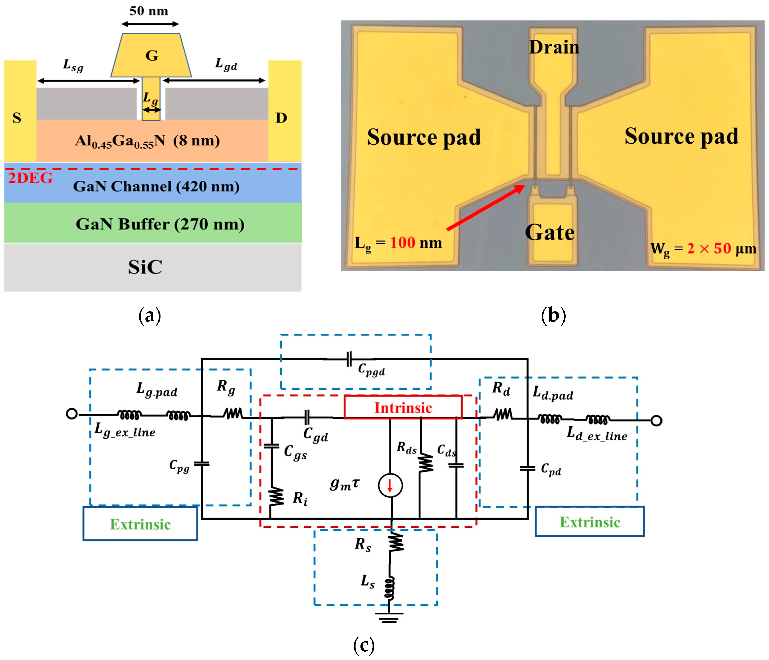
Figure 1. (a) Cross-sectional diagram of AlGaN/GaN HEMT device, (b) Real GaN HEMT device used for experiment, (c) Small-signal equivalent circuit of the device. Intrinsic and Extrinsic components of the device are indicating by red and blue dash lines respectively.
Electronics 12 03044 g001
Figure 2. (a) Linear relationship between ID& IG in 30 nm device, (b) 50 nm, and (c) 100 nm.
Electronics 12 03044 g002
Figure 3. (a) Z12 parameter indicates source resistance extraction, (b) Z22 parameter indicates drain resistance, and (c) Z11 parameter indicates gate resistance extraction at high frequencies.
Electronics 12 03044 g003
Figure 4. Dambrine’s circuit at cold-FET pinch-off condition.
Electronics 12 03044 g004
Figure 5. Corrected circuit at cold-FET condition.
Electronics 12 03044 g005
Figure 6. (a) Y-parameter extraction result at Vg = −4 V, Vds = 0 V, (b) pad capacitance extraction from Dambrine’s model, and (c) pad capacitances from our proposed model.
Electronics 12 03044 g006aElectronics 12 03044 g006b
Figure 7. (a) Step size of 1 GHz creates difficulties while calculating the pad capacitances. The values of the capacitances are not linear at low frequency. (b) Decreasing the step size (200 MHz) provides better accuracy for the calculation of the capacitances at low frequency.
Electronics 12 03044 g007
Figure 8. (a) Dambrine’s model and (b) adding depletion layer capacitance in the gate side in cold-FET circuit ADS result in Lg = 100 nm AlGaN/GaN HEMT.
Electronics 12 03044 g008
Figure 9. Inductance calcualtion using the cold FET de-embedding method for a GaN-HEMT with 2  ×   50   μ m  and gate length Lg = 100 nm. (a) represents gate inductance (Lg) extraction, (b) represents drain inductance (Ld) and (c) represents source inductance (Ls) extraction process.
Electronics 12 03044 g009
Figure 10. Conventional method showing discrepancy of resistances and capacitances (a) in 2  ×   25   μ m  devices, (b) after correcting the values measured values matches with modeled results. (c) In the high-frequency range, parasitic capacitances are not fully eliminated in 2  ×   50   μ m  devices. (d) Proposed model displays good correlation with model results.
Electronics 12 03044 g010
Table 1. Parasitic resistance calculations of Lg = 100 nm in bias condition (Vg = −4.0 V) pinch-off region.
FrequencyRs (Ω)Rd (Ω)Rg (Ω)Rch (Ω)
20 GHz3.957.918.123.52
25 GHz1.893.7816.897.3
30 GHz2.635.2616.474.52
35 GHz3.186.3515.251.66
40 GHz1.442.8814.275.14
Average 2.625.2316.204.42
Table 2. Parasitic resistance calculation of Lg = 100 nm in bias condition (Vg = 0.0 V and 1.0 V).
FrequencyRs (Ω)Rd (Ω)Rg (Ω)Rch (Ω)
20 GHz1.292.5814.4713.90
25 GHz0.871.7414.0414.74
30 GHz0.981.9613.4914.08
35 GHz1.062.1213.1713.60
40 GHz0.801.6012.7713.98
Average 1.002.0013.5814.06
Table 3. Parasitic resistance calculation of Lg = 100 nm in bias condition (Vg = 2.0 V).
FrequencyRs (Ω)Rd (Ω)Rg (Ω)Rch (Ω)
20 GHz1.262.5229.5413.16
25 GHz1.022.0424.3213.48
30 GHz1.122.2420.5112.88
35 GHz1.222.4418.2512.32
40 GHz1.062.1216.7912.42
Average 1.142.2721.8812.85
Rg displays very high value at Vg = 2.0 V.
Table 4. Comparison of pad capacitance.
ParametersDambrine’s Model Proposed Model
Cpg (fF)0.880.58
Cpd (fF)16.71.19
Table 5. Parameters extraction of 2  ×   25   μ m  and 2  ×   50   μ m .
Extrinsic/IntrinsicModel ParametersExtracted Values
For   2 × 25   μ m
Extracted Values
For   2 × 50   μ m
Extrinsic partRg15 Ω9.5 Ω
Rd26 Ω8.0 Ω
Rs13 Ω4.2 Ω
Lg0.1 pH4.1 pH
Ls20.3 pH26.3 pH
Ld24.5 pH23.4 pH
Intrinsic partCgs32 fF45 fF
Cgd3.6 fF12 fF
Ri1.38 Ω1.45 Ω
Gm20 mS26 mS
τ0.699 pico sec1.23 pico sec
Rds1500 Ω1800 Ω
Cds1.22 fF19 fF
Disclaimer/Publisher’s Note: The statements, opinions and data contained in all publications are solely those of the individual author(s) and contributor(s) and not of MDPI and/or the editor(s). MDPI and/or the editor(s) disclaim responsibility for any injury to people or property resulting from any ideas, methods, instructions or products referred to in the content.