Article

Research and Implementation of Intelligent Control System for Grassland Grazing Robotic Vehicle

1
College of Electronic Information Engineering, Inner Mongolia University, Hohhot 010021, China
2
State Key Laboratory of Reproductive Regulation and Breeding of Grassland Livestock, Hohhot 010020, China
*
Author to whom correspondence should be addressed.
Electronics 2023, 12(14), 3078; https://doi.org/10.3390/electronics12143078
Submission received: 15 June 2023 / Revised: 11 July 2023 / Accepted: 13 July 2023 / Published: 14 July 2023
(This article belongs to the Special Issue Recent Advances in Robotics and Automation Systems)

Abstract

:
In response to the complex animal husbandry environment, wide livestock range, and labor shortage in Inner Mongolia grasslands, this study designed an intelligent control system for robotic vehicles used in natural grazing grassland environments. The control system consists of software and hardware components and motion control algorithms. Based on the application characteristics of different mechanisms of the robotic vehicle, the motion control of the robotic vehicle is decomposed into longitudinal speed control and lateral steering control. The longitudinal speed control adopts the traditional Proportional-Integral-Differential (PID) control method. Since the hardware composition and internal angle calculation method of the steering system are complex and prone to deviations caused by external terrain, a lateral adaptive fuzzy PID controller was constructed with lateral deviation and deviation change rate as input variables and parameters K p , K i , and K d as outputs. The field test results show that when the longitudinal speed was set to 0.5 m/s, the adjustment time was 1.95 s, and the steady-state error was about 0. When the longitudinal speed was the same, the lateral adaptive fuzzy PID controller reduced the rise time by 0.77 s compared to traditional control methods, reduced overshoot and steady-state error by 2%, and quickly recovered to a steady state after being disturbed. The following test results show that the designed intelligent control system can achieve real-time tracking of targets and that the motion controllers can effectively control speed and steering angle. Therefore, the intelligent control system designed in this paper can effectively achieve stable and real-time control of the robotic vehicle.

1. Introduction

With the continuous development of intelligent animal husbandry, the research and application of intelligent robots in animal husbandry are receiving increasing attention from various countries and have achieved fruitful results [1]. The natural grassland area and livestock range in Inner Mongolia pastoral areas are large, and the economic benefits of animal husbandry are great. But at this stage, there are problems such as labor shortages, and low mechanization and scale in animal husbandry [2]. To reduce human resources, improve animal husbandry efficiency, and accurately and digitally monitor feeding behaviors and intake of herds, intelligent grazing robots have been applied in the animal husbandry process to replace manual monitoring. The geography of the grassland is complex, with rugged roads, gullies, and numerous mountain slopes, which have strong nonlinear characteristics. As a result, when the grazing robotic vehicles operate, they are easily affected by the terrain environment and lose stability. This places high demands on the motion control performance of robotic vehicles in grassland environments, such as the dynamic characteristics of the steering system, the accuracy and stability of the speed control system, and other aspects.
In recent years, with the rapid development of artificial intelligence and mobile robot technology, the research and development of intelligent robots used in animal husbandry has attracted wide attention, and their achievements have gradually been applied to the production and lives of farmers. L. Peng et al. developed an intelligent pig feeding system based on PLC, which has three parts: automatic feeding, environmental control, and an upper computer control interface; real-time control was achieved through the interface, which greatly improves the efficiency of pig feeding [3]. Mosquera et al. developed an automatic feeding system for dairy cows based on PLC that used multiple sensors and robotic arms for precise feeding, while also optimizing the feed ratio based on the weight of the milk [4]. C. Long et al. designed a mobile monitoring robot for livestock and poultry houses that monitored the breeding environment through various sensors and livestock using cameras and infrared temperature measuring devices. The collected data were uploaded to Alibaba Cloud for storage and viewing using Wi-Fi modules [5]. Usher et al. developed a mobile robot for poultry house management based on an Nvidia Jetson TX1 controller. It used an OpenCV algorithm to identify and transport eggs and chicken carcasses, and could monitor poultry growth status and environmental information [6]. Q. Feng et al. designed an epidemic prevention and disinfection robot, supporting both fully automated operation and remote-control operation, which can move along geomagnetic and RFID tags, and tested the sprayer. The nozzle sprayed droplets with a diameter of up to micrometers at a flow rate of 400–1200 mL/min [7]. Chanprakon et al. developed a UV disinfection robot for indoor disinfection based on the Raspberry Pi embedded platform [8].
Depending on the different control targets, the motion control of mobile robots can be divided into longitudinal speed control and lateral angle control [9]. Longitudinal motion control mainly refers to the precise control of the robot’s running speed or expected distance through the coordination of drivers and brakes [10]. In longitudinal motion control, PID control is the most widely used method, which does not require a specific system model and relies only on input deviations for control [11]. J. Han et al. proposed a fuzzy-gain PID controller based on the dynamic characteristics of hybrid robots based on traditional PID controllers, which enabled robots to achieve better control performance in any operating state [12]. Horizontal control can be divided into two parts: path tracking control and trajectory tracking control, with diverse control algorithms. Singhal designed an adaptive fractional order parallel fuzzy PID controller (AFO-PFPID) to achieve trajectory tracking control of a non-holonomic wheeled mobile robot (WMR) system due to the high degree of uncertainty in its motion state [13]. P. Shi et al. proposed a hybrid PID control theory based on improved model predictive control to increase the accuracy of intelligent vehicle path tracking. In lateral control, a relaxation factor was introduced based on traditional MPC to constrain the front wheel lateral deviation and improve the stability of vehicle control; in longitudinal control, a hybrid PID controller was designed for different road conditions to ensure the accuracy and real-time performance of the longitudinal control [14]. Abhijit et al. designed a hybrid fuzzy embedded PID control method for the stability and path planning of humanoid robots moving on uneven surfaces. To verify the performance of the controller, the parameters of the designed fuzzy PID controller were compared with those of the previously proposed method and showed improvements, a shorter adjustment time, and reduced overshoot [15]. Q. Xu et al. constructed a fuzzy PID controller to solve the problem of wheel deflection control of agricultural vehicles with four-wheel independent steering and conducted simulation experiments and field tests. The results showed that their steering control strategy has good real-time performance and effectively improves steering stability [16].
From the research of the above scholars, we can see that the selection of improved methods based on the traditional PID to control a mobile robot’s motion in a complex working environment can meet the requirements of stable and real-time control. However, the intelligent robots used in animal husbandry are mainly concentrated in tasks involving animal feeding, animal management and environmental monitoring, epidemic prevention, and disinfection and sterilization [17], while the intelligent robots applied for grazing are rarely studied. Therefore, the research on grazing robots can not only fill the gaps in the related research fields, but also provide key technical equipment for grassland animal husbandry, promoting the development of animal husbandry towards intelligence, increased welfare and scale, and gradually becoming an important way to ensure the sustainable development of animal husbandry.
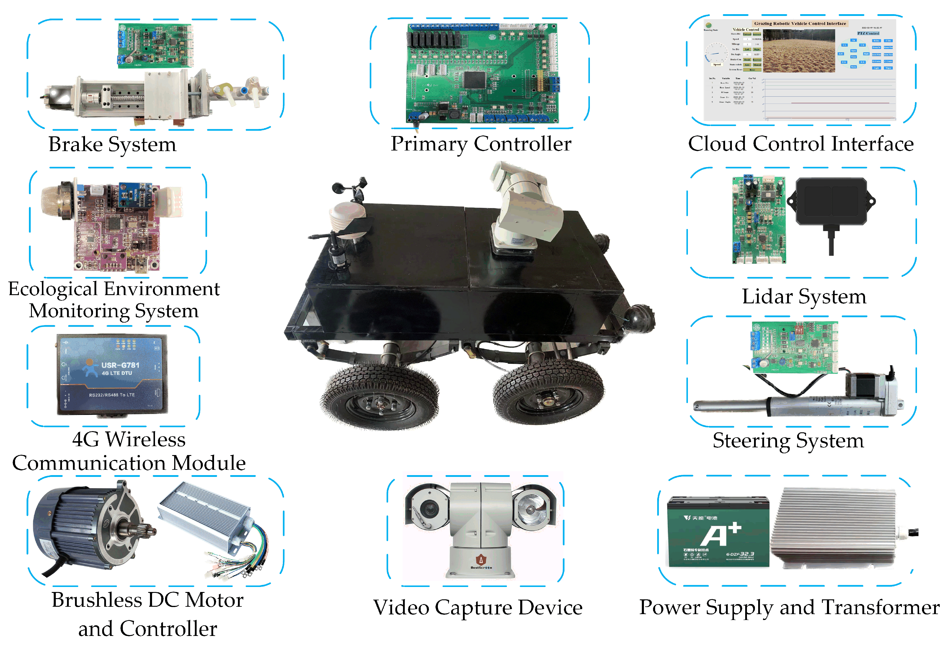
The overall design goal of the grazing robotic vehicle is to autonomously identify livestock and recognize obstacles in the wild environment, make path decisions and plans based on this information, or achieve remote semi-autonomous control through wireless communication modules and human-machine interaction interfaces. After receiving commands from these two parts, the bottom controllers perform motion control to follow the livestock or use devices such as horns to drive them away. In order to enhance the practicality of the robotic vehicle, a set of ecological environment monitoring systems was designed, which collect and store environmental information during the following process and make reasonable animal husbandry decisions based on this information. The underlying motion control of the robotic vehicle determines the real-time and stable motion control of the entire vehicle, therefore, the focus of this study is on the design and implementation of an intelligent control system for grazing robotic vehicles, including the design and implementation of various controllers and executing mechanisms, as well as the research and implementation of intelligent control algorithms.
Among the current motion control approaches for agricultural vehicles, the PID control method is the most widely used. It does not require the establishment of a specific system model and can only be controlled by the input deviation. However, it is difficult to adapt to complex systems and scenarios with large external disturbances. The core of fuzzy control is to use established fuzzy rules to control the system, which have good adaptability and can effectively improve the stability and real-time performance of the control system. This study combined fuzzy control with traditional PID control to optimize the motion control of grazing robotic vehicles.
In this paper, an intelligent control system for a grazing robotic vehicle was built for the complex and changing terrain of the grassland grazing environment. By designing a lateral adaptive fuzzy PID controller and a longitudinal PID constant speed controller, the problems of poor stability and real-time performance of steering and unstable speed changes in grassland environments can be solved. The simulation and field test results show that the designed control system can meet the control requirements and provide a reference for the control system design of intelligent robots in grassland grazing environments.

2. Components of the Control System

2.1. Overall Layout

The control system of the grazing robotic vehicle mainly consists of 10 parts, as shown in Figure 1, which can be summarized into three systems: the vehicle body system, the controllers and communication system, and the actuators and sensors.
In order to simplify the mechanical structure of the robotic vehicle and reduce the development cost, the steering mechanism adopts a stepper motor push rod as the driving device, and the longitudinal speed control mechanism adopts a brushless DC motor as the driving device. There is also a braking mechanism for emergency braking or reducing the vehicle’s speed. Compared to traditional differential control methods, this control method separates speed and angle control without requiring too many complex calculations. At the same time, each controller of the robotic vehicle adopts a modular design, with controllers for steering, speed regulation, braking, and other functions designed to facilitate maintenance and improve the applicability of the control system. Four 12 V lead-acid batteries are connected in series to form a 48 V, 32 Ah DC power supply for each part. The main parameters of the robotic vehicle are shown in Table 1.

2.2. Controller and Communication System Components

In order to improve the real-time performance and data processing ability of the vehicle’s control system, the controller section uses an architecture consisting of a primary and multiple secondary controllers. The primary controller uses an STM32F429IGT6 microprocessor as the control core, receiving data from the secondary controllers and sensors and transmitting these data to the cloud control interface through wireless communication modules. These instructions from the cloud control interface are processed and then distributed to secondary controllers for motion control. Using the STM32F103C8T6 microprocessor as the control core of each secondary controller, four secondary controllers, named steering, braking, lidar, and ecological environment monitoring system, were designed.
Using the primary controller as the primary communication node of the robotic vehicle, a CAN communication network is formed with the steering, braking, and lidar mechanisms through a TJA1050 CAN transceiver. The longitudinal speed control mechanism uses a timer (TIM) output pulse for speed control. With the cloud control interface through the RS485 communication interface, the USR-G781 4G wireless communication module through the Modbus-RTU protocol is used for data upload and command reception. IO pins are used to control relays for light and sound control. The block diagram of the complete vehicle controller and communication system is shown in Figure 2.

2.3. Cloud Control Interface Design

The cloud control interface consists of the USR-G781 4G wireless communication module and the accompanying cloud platform. As shown in Figure 3, this interface has multiple functional modules, such as switching the operation mode of the robotic vehicle, issuing commands, real-time query and storage of ecological environment data and self-motion data, and video supervision. In remote control mode, users can use this interface to view the status of livestock feeding activities through the bound high-definition pan tilt, and then issue commands such as steering, acceleration, deceleration, and braking to control the operation of the robotic vehicle.

3. Motion Mechanism Design

3.1. Design of the Steering Mechanism

The steering mechanism mainly consists of a steering controller, stepper motor push rod, steering linkage, displacement sensor, and limit sensor, as shown in Figure 4.
A stepper motor push rod as the steering drive, which is connected to the steering linkage for steering, and the displacement of the push rod is measured by a linear displacement sensor and converted to an angle in real-time within the controller. At this point, Figure 4 can be simplified to the structure shown in Figure 5.
The XOY coordinate system is established with point O as the origin; the AC section is the total stroke of the stepper motor push rod, and its displacement is set as 2L; δ A and δ B are the steering angles of the robotic vehicle; and β A and β B are the steering angles of the wheel. During the steering process, when the push rod is in position A, the displacement of the push rod is 0, and the vehicle body is at the maximum left turn angle. When the push rod is in position B, the stretch of the push rod is half of its stroke, the displacement is L at this point, and the steering angle of the vehicle body is 0°. When the motor push rod is in position C, the stretch of the push rod reaches its maximum stroke, and the displacement is 2L; at this point, the vehicle body is at the maximum angle of a right turn. After actual measurement, the maximum turning angles on both sides of the vehicle body were 32°, that is, δ A = δ B = 32 ° , and half of the push rod stroke is L = 75 mm.
By correcting the steering angle in Figure 5 to ensure that when the steering angle is 0°, the wheels are on the central axis. When the steering angle is −32°, the wheels are at the maximum left-turn value. When the steering angle is +32°, the wheels are at the maximum right-turn value. The final steering angle calculation method is shown in Equation (1):
δ = t a n 1 75 y H       y 75   m m + t a n 1 y 75 H       y > 75   m m  
where δ is the angle value calculated internally by the processor (°); H is the distance of the OB section, H = 120 mm; and y is the displacement measured by the displacement sensor (mm). ‘ ’ indicates the steering angle is to the left; ‘ + ’ indicates the steering angle is to the right.
After the above analysis, the LongXiang BJXL stepper motor push rod gear reducer with a stroke of 150 mm was selected as the actuator, equipped with a 42-stepper motor with a working voltage of 9–36 V and a maximum thrust of 500 N. To obtain real-time angles during the movement of the robotic vehicle, a Hermitt KTC-150 mm linear displacement sensor was used in conjunction with a stepper motor push rod for angle measurement; its working voltage is 0–24 V with conventional analog output. A proximity switch was used to limit the travel of the actuator; the specific type is the Omron TL-Q5MB1-Z DC 3-wire PNP normally open type.
Using the DMA method of the internal ADC interface of the STM32 microprocessor for the acquisition of the displacement sensor output data, the data are calculated using Equation (2):
v m e a s u r e = A D C v a l u e 2 12 × v r e f  
where v m e a s u r e is the voltage value of the displacement sensor (V); A D C v a l u e   is the data of the ADC interface measured by the microprocessor; and v r e f is the reference voltage, v r e f = 3.3   V .
Due to the accuracy of the linear displacement sensor, its output voltage value is not strictly linear with the displacement value, so curve fitting is necessary. The voltage value and actual displacement value of the displacement sensor are collected multiple times, and curve fitting tools are used to fit the output curve of its displacement changing with voltage, and the relationship between the final displacement y . The voltage value v m e a s u r e can be calculated as shown in Equation (3):
y = 0.2119 v m e a s u r e 3 + 1.2452 v m e a s u r e 2 10.9178 v m e a s u r e + 15.9743  
After obtaining the displacement y , the angle value can be calculated according to Equation (1) above.

3.2. Design of the Longitudinal Speed Regulation Mechanism

The longitudinal speed regulation mechanism refers to a system used to drive the grazing robotic vehicle to achieve forward, backward, and acceleration or deceleration functions; it included a DC motor, motor controller, encoder, and a rear wheel differential mechanism. Its design diagram is shown in Figure 6.
In this paper, a brushless DC motor with a rated voltage of 48 V, a power of 1 kW, and a rated speed of 3000 rpm was selected, together with a matching 1 kW motor driver and an Omron 1000-line EB62-CWZ1X linear incremental photoelectric encoder for speed measurements.
The encoder mode of the STM32 microprocessor’s internal timer (TIM) was used to capture the encoder output pulses by the quadruple frequency method to obtain the motor speed, and the direction of rotation of the motor can be obtained by the sequence of the AB two-phase pulse outputs. The calculation method for the motor’s real-time speed N B L D C (r/min) is shown in Equation (4):
N B L D C = n p u l s e 1000 × 4 × t f a c t o r × 60  
where n p u l s e is the amount of pulse between two readings, and t f a c t o r is the time factor.
Due to the speed ratio of the motor to the wheel being four and the radius R of the wheel being known, the running speed v (m/s) of the robotic vehicle can be calculated using Equation (5):
v = N B L D C 60 × 2 π × R × 4  

4. Motion Controller Design

In order to cope with the impact of complex terrain on the robotic vehicle and achieve smooth operation, the entire vehicle control of the robotic vehicle is decomposed into lateral and longitudinal controls. Based on the characteristics of the two motion mechanisms, a lateral adaptive fuzzy PID controller and a longitudinal constant-speed PID controller were designed.

4.1. Design of the Longitudinal Constant Speed PID Controller

The longitudinal speed control structure of the robotic vehicle is simple, and using a traditional PID control strategy can achieve a good control effect. The encoder is used to collect the real-time speed of the robotic vehicle, and the deviation between the real-time speed obtained and the target speed is used as the input of the longitudinal constant speed PID controller. The controller calculates and outputs pulses with different duty ratios in real-time as the input signal of the motor controller, thereby changing the speed of the motor and achieving real-time speed regulation The design diagram of the controller is shown in Figure 7.
The composition of the speed control mechanism is simple and does not have integral components, so a positional PID controller is used for speed control, which is discretized into Equation (6):
u k = K p e k + K i e k + K d e k e k 1  
where u k is the output of the PID controller at time k; e k is the deviation at time k; and e k 1 is the deviation at time k − 1.
The motor speed changes with the control voltage input to the motor controller, and the voltage signal input to the motor controller is digital in nature and is determined by the duty cycle of the PWM pulse output from the microcontroller. The microcontroller output PWM pulse frequency was set to 100 kHz, and the duty cycle varies within [−9000, 9000], corresponding to a voltage value variation range of [0, 3.3] V. When the microprocessor detects a negative duty cycle, it controls the motor to reverse by controlling the relay’s engagement.
Using the Z-N method for PID parameter tuning, and after multiple practical tests, K p was set to 5, K i was set to 2.2, and K d was set to 0.

4.2. Design of the Horizontal Adaptive Fuzzy PID Controller

The grazing robotic vehicle often runs in complex and open outdoor environments with rugged roads and strong non-linear characteristics. To ensure stable operation and precise control of the robotic vehicle, real-time adjustment of control parameters is required during operation to cope with the impact of constantly changing external terrain. Once the parameters of traditional PID controllers are determined, they are difficult to change during operation, resulting in poor adaptability and control effectiveness, making it difficult to meet the control requirements in complex and ever-changing environments [18]. Therefore, this study designed an adaptive fuzzy PID controller to improve the above problems.
The adaptive fuzzy PID controller designed in this study is a fuzzy logic control structure with 2 inputs, 3 outputs, and 49 fuzzy control rules [19]. The control system design structure is shown in Figure 8.
The deviation e and deviation change rate ec between the target angle of the robotic vehicle and the actual measurement angle of the linear displacement sensor are used as input variables for the controller; after quantification and fuzzification, they correspond to the parameters of the fuzzy domains E and EC. Then, based on the 49 established fuzzy control rules, fuzzy inference is used to obtain the fuzzy output variables Δ K p ,   Δ K i , and Δ K d . These parameters are output to the PID controller after defuzzification, and the final control parameters are synthesized through a linear relationship with the initial parameters of the PID controller, achieving online adjustment of the PID control parameters [20]. Finally, the output “u” is obtained and transmitted to the steering controller for angle control. The variables and values defined to implement the above process are shown in Table 2.
The triangular membership function is used as the middle segment function of the input and output variables, and Gaussian functions are used on both sides to enhance the adaptability of the controller. The membership function curves are shown in Figure 9. The three-dimensional output surface of the fuzzy control variables Δ K p ,   Δ K i , and Δ K d are shown in Figure 10. After summarizing the technical knowledge of engineering personnel or experts [21,22] and combining it with practical testing, the fuzzy rules for the three output variables of the adaptive fuzzy PID controller were obtained and are shown in Table 3, Table 4 and Table 5.
After obtaining the output of the fuzzy controller at a certain moment, the output parameters cannot be directly used to correct the PID parameters. Instead, the self-tuning gain correction parameters need to be obtained by multiplying them by the corresponding proportional factor. The control parameters are synthesized using linear relationships with the initial parameters of the PID controller. Finally, the control parameters are inputted to the PID controller for control, and the final parameter self-tuning formula [23] is shown in Equation (7):
K p k = K p 0 + α p · Δ K p k K i k = K i 0 + α i · Δ K i k K d k = K d 0 + α d · Δ K d k  
where K p k , K i k , and K d k are the final outputs of the adaptive fuzzy PID controller; α p , α i , and α d are the quantification factors; and K p 0 , K i 0 , and K d 0 are the initial parameters of the PID controller, which need to be obtained according to the relevant methods.

4.3. Simulation and Analysis

By sending a certain steering angle command to the steering control system and obtaining its response, the input and output data of the steering system angle are collected. Using the System Identification toolbox of MATLAB software to identify the approximate transfer function of the system and then combining experiments and testing to modify the obtained transfer function, the transfer function of the steering system was obtained and is shown in Equation (8):
G s = 6.5 s + 3.28 s 3 + 2.358 s 2 + 6.42 s + 1  
The input of this transfer function is the deviation between the target steering angle and the actual value, and the output is the steering angle.
Using the Fuzzy toolbox and Simulink simulation tool of MATLAB software and based on the design of the adaptive fuzzy PID controller mentioned above, a simulation model of the traditional PID controller and the adaptive fuzzy PID controller was built, and a comparison was made between the two controllers. The simulation model is shown in Figure 11.
Using the Z-N method and combined with actual testing, the initial PID parameters of the controller were set to be K p 0 = 16 , K i 0 = 3.8 , and K d 0 = 2.6 . During the simulation, the sampling time was set to 1 ms, and a step signal with an amplitude of 1 was the input. At the 5th second, a step signal with an amplitude of 0.5 was added to simulate the interference signal. The simulation results are shown in Figure 12.
By comparing the simulation waveforms of the two controllers, it can be seen that the designed lateral adaptive fuzzy PID controller had basically the same rise time as the traditional PID controller, but had an increase of 0.4 s in adjustment time, a decrease of 1% in steady-state error control, and a decrease of 5% in overshoot control. At the same time, compared to traditional PID controllers in terms of anti-interference performance, it can quickly return to the stable state.
From the simulation result, it can be seen that selecting an adaptive fuzzy PID controller as the steering controller for the grazing robotic vehicle can meet the control requirements of stable and fast control.

5. Field Test and Analysis of Motion Controllers

5.1. Motion Controller Test

The purpose of the motion controller testing was to preliminarily verify the control performance of the two designed controllers in different environments. According to the different test items and test requirements, two locations with different ground conditions were selected as test locations, and two groups of control tests were conducted on the two motion controllers: the first group was the flat ground of a playground, which was used to simulate the driving conditions in the flat terrain of the grassland; the second group was a grassland area with complex terrain, where resistance was artificially increased during operation to simulate driving conditions in complex grassland terrain. The testing location is shown in Figure 13.
During the test, the commands were issued through the cloud control interface, and the frequency of sensor data acquisition was set to 50 Hz, while the control frequency of the motion controller was also 50 Hz.

5.1.1. Longitudinal Constant Speed PID Controller Test

Test 1: The test was carried out on a relatively flat surface, as shown in Figure 13a, with speed settings ranging from 0 to 0.5 m/s to 0.8 m/s to 1 m/s, to analyze the variation in regulation time, overshoot, steady-state error, and other indicators.
The test result is shown in Figure 14. It took 1.35 s for the robotic vehicle to move, which includes receiving commands and overcoming its static torque. Then, under the action of the longitudinal constant speed PID controller, the speed quickly reached the set target. From the analysis of the first segment, the rise time was 1.62 s, the adjustment time was 1.95 s, and the overshoot was 6%. After the adjustment was stable, the steady-state error of the vehicle’s speed was 0, but there was slight shaking.
Test 2: The speed disturbance test was conducted in the grassland environment shown in Figure 13b. At the beginning of the test, the speed of the robotic vehicle was set to 1 m/s, and external resistance was artificially applied during driving to simulate the situation of the robotic vehicle being disturbed by external interference from a complex environment and to verify the dynamic characteristics of the longitudinal constant speed controller.
The test result is shown in Figure 15.
The test results show that the longitudinal speed PID controller could quickly adjust the pulse when disturbed by external resistance, so that the robotic vehicle could quickly recover to the target speed. The time from the speed change to 0 due to external disturbances to the recovery of the set speed did not exceed 5 s.

5.1.2. Lateral Adaptive Fuzzy PID Controller Test

Test 1: The test was conducted on a flat surface, as shown in Figure 13a. The longitudinal speed of the robotic vehicle was set at 0.5 m/s, and a command to turn left at 20° was issued through the cloud platform. The experimental data were recorded to compare the control performance of traditional PID controllers and adaptive fuzzy PID controllers.
The experimental results are shown in Figure 16.
The test results show that under the same set target, the adaptive fuzzy PID controller reduced the rise time by 0.77 s, the adjustment time by 1.12 s, the overshoot by about 2%, and the steady-state error by 2% compared to traditional PID controllers, which were closer to the simulation results.
Test 2: The steering angle disturbance test was conducted in the grassland environment shown in Figure 13b. When the longitudinal speed of the robotic vehicle was 0.5 m/s, a left turn command of 20° was issued through the cloud platform, and external resistance was artificially applied to interfere with the robotic vehicle, simulating the situation when the robotic vehicle was disturbed by external lateral resistance during operation. This was used to compare the control performance between the lateral adaptive fuzzy PID controller and the traditional PID controller in complex environments.
The test results are shown in Figure 17. Using the first section of the figure as an example for analysis, the results show that the rise time and adjustment time of the lateral adaptive fuzzy PID controller were the same, about 2 s, and the overshoot was about 0, while the rise time of the traditional PID controller was about 2.5 s and the adjustment time was about 4 s. At the same time, there was a large overshoot and steady-state error of about 8%.
It can be seen that the designed lateral adaptive fuzzy PID controller has a lower rise time and adjustment time when disturbed than the traditional PID controller and can greatly suppress overshoot and reduce steady-state errors.

5.2. Following Test

The following test was carried out using the designed lidar system in the location shown in Figure 18. The purpose of the following testing was to verify the intelligent control system of the robotic vehicle’s ability to follow livestock in natural environments and the control performance of the designed motion control system. During the following process, the target distance to be followed (median distance value) was set to 20 m, the maximum speed of the robotic vehicle was set to 0.8 m/s, and the lidar scanning range was set to 120°; the speed, steering angle, and lidar-scanned target distance information of the robotic vehicle were recorded at a frequency of 5 Hz.
The following process mainly depends on the lidar controller collecting the minimum distance D_min and the corresponding angle θ_min between the vehicle and the target object, comparing them with the vehicle’s own motion, and outputting control commands for the autonomous running control of the vehicle according to the process shown in Figure 19. In the following process, Target_Dis is the set median distance value to determine the relative distance between the vehicle and the target object, and V_Target is the maximum speed of the vehicle.
The above data were collected and plotted in a graph, as shown in Figure 20. In Figure 20, the blue, black, and red lines represent the angle value, distance value, and speed value of the robotic vehicle (for a clearer display, the speed value was expanded ten times before plotting).
It can be seen that, at the beginning, the distance between the robotic vehicle and the target was less than the set median distance value. At this time, the longitudinal constant speed controller accelerated to follow the target, reached the set maximum speed after 1.5 s, and maintained a uniform motion to follow the target; after approximately 4.1 s, it reached the set median distance value. At 8.9 s, the target turned, and the steering controller began to follow the target. After approximately 10 s of adjustment, the angle deviation between the robotic vehicle and the target returned to 0°. The test results show that the robotic vehicle can achieve real-time tracking of targets and that the motion controller can effectively control speed and steering angle.

6. Conclusions

This study designed an intelligent grazing robotic vehicle for natural grazing environments to solve the problem of a shortage of manpower in the wide range of animal husbandry in Inner Mongolia. Firstly, the motion mechanism of the whole vehicle was designed, and the corresponding controller was designed based on STM32 series microprocessors. Secondly, in order to achieve stable and real-time control of the grazing robotic vehicle in the rugged environment of the field, a longitudinal constant speed PID controller and a lateral adaptive fuzzy PID controller were designed based on the different characteristics of the hardware structure to control the entire vehicle. Finally, simulation experiments and field experiments were conducted to test the controller. The test results show that the control performance of the designed longitudinal PID constant speed controller can meet the requirements in complex environments. The lateral adaptive fuzzy PID controller can effectively cope with external interference, suppress overshoot, and achieve fast and stable steering adjustment. It can quickly recover to a steady state when disturbed and has good anti-interference performance. The following test results show that the designed intelligent control system can effectively realize the real-time tracking of the target and that the motion controller can effectively control the speed and steering angle of the vehicle. This study provides a technical reference for precise tracking of animal populations in grassland grazing environments and a feasible technical means for intelligent animal husbandry.

Author Contributions

Conceptualization, H.Z. and D.H.; methodology, H.Z. and D.H.; software, H.Z., M.H. and Y.M.; validation, H.Z., Y.M. and W.F.; formal analysis, H.Z. and J.X.; investigation, H.Z. and M.H.; resources, H.Z., M.H., W.F. and J.X.; data curation, H.Z. and Y.M.; writing—original draft preparation, H.Z.; writing—review and editing, H.Z., D.H. and Y.M.; visualization, H.Z., J.X. and W.F.; supervision, D.H., M.H. and Y.M.; project administration, H.Z. and D.H.; funding acquisition, D.H. All authors have read and agreed to the published version of the manuscript.

Funding

This research was funded by the National Key R&D Program of China (Funder: Ding Han, Grant No.2022YFF1300604-04), and the Major Science and Technology Projects of the Inner Mongolia Autonomous Region (Funder: Ding Han, Grant No. 2021ZD0019-4).

Data Availability Statement

Some or all of the data, models, or code generated or used during the study are available from the corresponding author by request (raw data, site data, algorithm model).

Acknowledgments

This work was supported by the National Key RD Program of China (Funder: Ding Han, Grant No.2022YFF1300604-04), and the Major Science and Technology Projects of the Inner Mongolia Autonomous Region (Funder: Ding Han, Grant No. 2021ZD0019-4). The authors would like to thank the funding bodies for their financial support.

Conflicts of Interest

The authors declare no conflict of interest.

References

  1. Jin, Y.; Liu, J.; Xu, Z.; Yuan, S.; Li, P.; Wang, J. Development status and trend of agricultural robot technology. Int. J. Agric. Biol. Eng. 2021, 14, 1–19. [Google Scholar] [CrossRef]
  2. Song, Y.; Fan, X.; Wang, X. Technological Optimization for High-Quality Development of China’s Animal Husbandry. J. Huazhong Agric. Univ. (Nat. Sci. Ed.) 2022, 41, 87–95. [Google Scholar] [CrossRef]
  3. Peng, L.; Jiang, Z. Intelligent automatic pig feeding system based on PLC. Rev. Científica Fac. Cienc. Vet. 2020, 30, 2479–2490. [Google Scholar]
  4. Mosquera, I.L.Q.; Fierro, J.E.R.; Zacarias, J.R.O.; Montero, J.B.; Quijano, S.A.C.; Huamanchahua, D. Design of an Automated System for Cattle-Feed Dispensing in Cattle-Cows. In Proceedings of the 2021 IEEE 12th Annual Ubiquitous Computing, Electronics & Mobile Communication Conference (UEMCON), New York, NY, USA, 1–4 December 2021; pp. 671–675. [Google Scholar] [CrossRef]
  5. Long, C.; Tan, H.; Zhu, M.; Xin, R.; Qin, G.; Huang, P. Development of a Mobile Intelligent Monitoring Platform for Livestock and Poultry Housing. J. Agric. Eng. 2021, 37, 68–75. [Google Scholar]
  6. Usher, C.T.; Daley, W.D.; Joffe, B.P.; Muni, A. Robotics for poultry house management. In Proceedings of the 2017 ASABE Annual International Meeting, Spokane, WA, USA, 16–19 July 2017; p. 1. [Google Scholar] [CrossRef]
  7. Feng, Q.; Wang, B.; Zhang, W.; Li, X. Development and Test of Spraying Robot for Anti-epidemic and Disinfection in Animal Housing. In Proceedings of the 2021 WRC Symposium on Advanced Robotics and Automation (WRC SARA), Beijing, China, 11 September 2021; pp. 24–29. [Google Scholar] [CrossRef]
  8. Chanprakon, P.; Sae-Oung, T.; Treebupachatsakul, T.; Hannanta-Anan, P.; Piyawattanametha, W. An Ultra-violet sterilization robot for disinfection. In Proceedings of the 2019 5th International Conference on Engineering, Applied Sciences and Technology (ICEAST), Luang Prabang, Laos, 2–5 July 2019; pp. 1–4. [Google Scholar]
  9. Xiong, L.; Yang, X.; Zhuo, G.; Leng, B.; Zhang, R. Review on Motion Control of Autonomous Vehicles. J. Mech. Eng. 2020, 56, 127–143. [Google Scholar]
  10. Liu, K.-Q.; Zhong, S.-S.; Zhao, K.; Song, Y. Motion control and positioning system of multi-sensor tunnel defect inspection robot: From methodology to application. Sci. Rep. 2023, 13, 232. [Google Scholar] [CrossRef] [PubMed]
  11. Li, J.; Zhou, Y.; Dong, M.; Rong, X. Isokinetic muscle strength training strategy of an ankle rehabilitation robot based on adaptive gain and cascade PID control. IEEE Trans. Cogn. Dev. Syst. 2022, 15, 100–110. [Google Scholar] [CrossRef]
  12. Han, J.; Shan, X.; Liu, H.; Xiao, J.; Huang, T. Fuzzy gain scheduling PID control of a hybrid robot based on dynamic characteristics. Mech. Mach. Theory 2023, 184, 105283. [Google Scholar] [CrossRef]
  13. Singhal, K.; Kumar, V.; Rana, K. Robust trajectory tracking control of non-holonomic wheeled mobile robots using an adaptive fractional order parallel fuzzy PID controller. J. Franklin Inst. 2022, 359, 4160–4215. [Google Scholar] [CrossRef]
  14. Peicheng, S.; Li, L.; Ni, X.; Yang, A. Intelligent Vehicle Path Tracking Control Based on Improved MPC and Hybrid PID. IEEE Access 2022, 10, 94133–94144. [Google Scholar] [CrossRef]
  15. Mahapatro, A.; Dhal, P.R.; Parhi, D.R.; Muni, M.K.; Sahu, C.; Patra, S.K. Towards stabilization and navigational analysis of humanoids in complex arena using a hybridized fuzzy embedded PID controller approach. Expert Syst. Appl. 2023, 213, 119251. [Google Scholar] [CrossRef]
  16. Xu, Q.; Li, H.; Wang, Q.; Wang, C. Wheel Deflection Control of Agricultural Vehicles with Four-Wheel Independent Omnidirectional Steering. Actuators 2021, 10, 334. [Google Scholar] [CrossRef]
  17. Cheng, C.; Fu, J.; Su, H.; Ren, L. Recent Advancements in Agriculture Robots: Benefits and Challenges. Machines 2023, 11, 48. [Google Scholar] [CrossRef]
  18. Samuel, M.; Yahya, K.; Attar, H.; Amer, A.; Mohamed, M.; Badmos, T.A. Evaluating the Performance of Fuzzy-PID Control for Lane Recognition and Lane-Keeping in Vehicle Simulations. Electronics 2023, 12, 724. [Google Scholar] [CrossRef]
  19. Han, S.-Y.; Dong, J.-F.; Zhou, J.; Chen, Y.-H. Adaptive Fuzzy PID Control Strategy for Vehicle Active Suspension Based on Road Evaluation. Electronics 2022, 11, 921. [Google Scholar] [CrossRef]
  20. Yao, Y.; Chen, X.; Ji, C.; Chen, J.; Zhang, H.; Pan, F. Design and Experiment of Individual Drive for Precision Maize Seeder Based on Fuzzy PID Control. J. Agric. Eng. 2022, 38, 12–21. [Google Scholar]
  21. Sain, D.; Praharaj, M.; Bosukonda, M.M. A simple modelling strategy for integer order and fractional order interval type-2 fuzzy PID controllers with their simulation and real-time implementation. Expert Syst. Appl. 2022, 202, 117196. [Google Scholar] [CrossRef]
  22. Liu, Y.; Jiang, D.; Yun, J.; Sun, Y.; Li, C.; Jiang, G.; Kong, J.; Tao, B.; Fang, Z. Self-tuning control of manipulator positioning based on fuzzy PID and PSO algorithm. Front. Bioeng. Biotechnol. 2022, 9, 1443. [Google Scholar] [CrossRef] [PubMed]
  23. Han, S.; Wang, W.; Wang, Y.; Liu, G. Opening and Closing Positioning Control of the Seedling Picking-Up Mechanism Based on Fuzzy-PID Control Algorithm. Processes 2022, 10, 1349. [Google Scholar] [CrossRef]
Figure 1. Components of the control system.
Electronics 12 03078 g001
Figure 2. Controller and communication system block diagram.
Electronics 12 03078 g002
Figure 3. The cloud control interface.
Electronics 12 03078 g003
Figure 4. Schematic diagram of the steering mechanism.
Electronics 12 03078 g004
Figure 5. Simplified diagram of the steering mechanism.
Electronics 12 03078 g005
Figure 6. Schematic diagram of the longitudinal speed regulation mechanism.
Electronics 12 03078 g006
Figure 7. Structure of the longitudinal constant-speed PID controller.
Electronics 12 03078 g007
Figure 8. Structure of the lateral adaptive fuzzy PID controller.
Electronics 12 03078 g008
Figure 9. The membership function curves of the input and output variables: (a) input variable e; (b) input variable ec; (c) output variables Δ K p and Δ K d ; (d) output variable Δ K i .
Electronics 12 03078 g009
Figure 10. The three-dimensional output surface of the fuzzy control output variables: (a) Δ K p   output surface; (b) Δ K i   output surface; (c) Δ K d   output surface.
Electronics 12 03078 g010
Figure 11. Simulation model.
Electronics 12 03078 g011
Figure 12. Simulation results.
Electronics 12 03078 g012
Figure 13. Test locations of motion controllers: (a) flat ground; (b) grass environment.
Electronics 12 03078 g013
Figure 14. Continuous speed change curve.
Electronics 12 03078 g014
Figure 15. Curve of speed variation due to disturbance.
Electronics 12 03078 g015
Figure 16. Steering angle change curve.
Electronics 12 03078 g016
Figure 17. Curve of steering angle variation due to disturbance.
Electronics 12 03078 g017
Figure 18. Test location for the following test.
Electronics 12 03078 g018
Figure 19. Following process.
Electronics 12 03078 g019
Figure 20. Results of the following test.
Electronics 12 03078 g020
Table 1. Main parameters of the robotic vehicle.
ParametersValues
Overall size (cm)150 × 120 × 65
Total weight (kg)145
Wheel radius (cm)20
Running speed (m/s)≤5
Running acceleration (m/s2)≤2
Steering angle (°)−32–+32
Braking distance (cm)≤262
Braking time (s)≤2
Running time (h)≥3
Table 2. Parameter setting of the adaptive fuzzy PID controller.
Input/Output Variableeec Δ k p Δ k i Δ k d
Linguistic variableEEC Δ K p Δ K i Δ K d
Basic domain[−32 +32][−64 +64][−6 +6][−1 +1][−3 +3]
Fuzzy subset[NB NM NS ZO PS PM PB]
Fuzzy domain[−6 +6][−3 +3][−3 +3][−1 +1][−3 +3]
Quantification factor0.18750.046875211
Table 3. Δ K p fuzzy control rules.
Δ K p ec
NBNMNSZOPSPMPB
eNBPBPBPMPMPSZOZO
NMPBPBPMPSPSZONS
NSPMPMPMPSZONSNS
ZOPMPMPSZONSNMNM
PSPSPSZONSNSNMNM
PMPSZONSNMNMNMNB
PBZOZONMNMNMNBNB
Table 4. Δ K i fuzzy control rules.
Δ K i ec
NBNMNSZOPSPMPB
eNBNBNBNMNMNSZOZO
NMNBNBNMNSNSZOZO
NSNBNMNSNSZOPSPS
ZONMNMNSZOZOPMPM
PSNMNSZOPSPSPMPB
PMZOZOPSPSPMPBPB
PBZOZOPSPMPMPBPB
Table 5. Δ K d fuzzy control rules.
Δ K d ec
NBNMNSZOPSPMPB
eNBPSNSNBNBNBNMPS
NMPSNSNBNMNMNSZO
NSZONSNMNMNSNSZO
ZOZONSNSNSNSNSZO
PSZOZOZOZOZOZOZO
PMPBNSPSPSPSPSPB
PBPBPMPMPMPSPSPB
Disclaimer/Publisher’s Note: The statements, opinions and data contained in all publications are solely those of the individual author(s) and contributor(s) and not of MDPI and/or the editor(s). MDPI and/or the editor(s) disclaim responsibility for any injury to people or property resulting from any ideas, methods, instructions or products referred to in the content.

