Article

CUDA-Optimized GPU Acceleration of 3GPP 3D Channel Model Simulations for 5G Network Planning

1
Department of Electronics and Telecommunications, Politecnico di Torino, 10129 Turin, Italy
2
Telecom Italia S.p.A., 00198 Roma, Italy
*
Author to whom correspondence should be addressed.
Electronics 2023, 12(15), 3214; https://doi.org/10.3390/electronics12153214
Submission received: 9 June 2023 / Revised: 9 July 2023 / Accepted: 20 July 2023 / Published: 25 July 2023

Abstract

:
The simulation of massive multiple-input multiple-output (MIMO) channel models is becoming increasingly important for testing and validation of fifth-generation new radio (5G NR) wireless networks and beyond. However, simulation performance tends to be limited when modeling a large number of antenna elements combined with a complex and realistic representation of propagation conditions. In this paper, we propose an efficient implementation of a 3rd Generation Partnership Project (3GPP) three-dimensional (3D) channel model, specifically designed for graphics processing unit (GPU) platforms, with the goal of minimizing the computational time required for channel simulation. The channel model is highly parameterized to encompass a wide range of configurations required for real-world optimized 5G NR network deployments. We use several compute unified device architecture (CUDA)-based optimization techniques to exploit the parallelism and memory hierarchy of the GPU. Experimental data show that the developed system achieves an overall speedup of about 240× compared to the original C++ model executed on an Intel processor. Compared to a design previously accelerated on a datacenter-class field programmable gate array (FPGA), the GPU design has a 33.3% higher single-precision performance but a 7.5% higher power consumption. The proposed GPU accelerator can provide fast and accurate channel simulations for 5G NR network planning and optimization.

1. Introduction

Mobile communications have become an increasingly important part of modern life. They make it possible to perform routine tasks such as making video calls while traveling or staying in touch with family and the office from anywhere in the world [1,2,3,4]. The process of digitization began in the early 1990s with the introduction of secondgeneration cellular technologies [5]. Cellular technologies are undergoing continuous service development to improve customer experience and provide a higher level of service. The number of mobile devices such as smartphones, tablets, Internet of Things (IoT) devices, and laptops are expected to reach around 28.5 billion networked devices by the end of 2023 [6]. This increases the demand for higher throughput, lower latency, and higher quality of service, which are the main drivers for the introduction of the fifth-generation (5G) wireless communication standard [7]. The radio link is by far the most important part of any cellular technology. Its simulation must closely take into account propagation in real-world environments in order to predict and optimize network coverage and minimize post-deployment on-field measurements.
Several channel models for massive multiple-input multiple-output (MIMO)-based communication systems have been reported in the most recent literature [8,9,10,11,12]. The International Telecommunication Union (ITU) has defined the requirements for the International Mobile Telecommunications 2020 (IMT-2020) channel model with support for enhanced mobile broadband (eMBB), ultra-reliable and low-latency communications (URLLC) and massive machine-type communications (mMTC) [8].
The COST 2100 model [9] is a geometry-based stochastic model (GSCM) for MIMO channels with cluster power and delays derived from fixed geometry and therefore has limited support for dual mobility propagation scenarios. Weiler et al. [10] presented a quasi-deterministic channel model where the channel impulse response (CIR) is a combination of a few strong quasi-deterministic rays, flashing rays, and weak random rays. METIS [11] is a ray-tracing based channel model that supports propagation scenarios such as blocking, diffraction, specular reflection, and spherical wave propagation.
However, existing channel model simulators are either too simple to accurately replicate the propagation environment or too computationally expensive to produce meaningful results in a reasonable amount of time. In addition, most existing simulators are designed for central processing unit (CPU) platforms, which have limited parallelism and throughput. Therefore, there is a need for efficient and accurate channel model simulators that can run on parallel platforms such as graphics processing units (GPUs)s, which offer high performance and scalability. This article proposes a GPU-based hardware acceleration for the 3rd Generation Partnership Project (3GPP) three-dimensional (3D) channel model, which is a highly parameterized and realistic channel model for fifth-generation new radio (5G NR) networks, and shows that the proposed GPU accelerator can significantly improve the simulation speed and accuracy over a CPU-based C++ model, and also has higher single-precision performance than a previously designedfield programmable gate array (FPGA)-based accelerator.
The rest of the paper is organized as follows. Section 2 discusses previous related work. Section 3 discusses the importance of 3D channel modeling in MIMO communication techniques and briefly describes the 3GPP channel model. Section 4 presents an introduction to GPU and compute unified device architecture (CUDA) programming, followed by optimization methods for GPU-based hardware acceleration and its key benefits. The architecture of the proposed accelerator is outlined in Section 5, and the impact of various optimizations on the final result is analyzed in Section 6. Finally, conclusions are drawn in Section 7.

2. Related Work

The field-testing and validation of wireless systems is expensive both in terms of equipment cost and time to market. This step can be replaced by fast and accurate software-based models with high repeatability. Several channel simulators have been reported in the literature [13,14,15,16,17]. Sun et al. [13] proposed a geometry-based channel model simulator for the link and physical layers. Jaeckel et al. [14] proposed ground reflection components to the existing geometry-based channel models. Ju et al. [15] presented a model simulator for spatially consistent channel realizations using pedestrian measurements for human blockage. Pessoa et al. [17] presented a simulator with support for dual mobility.
General-purpose CPU-based channel simulators are either too simple to accurately replicate the propagation environment or too computationally complex to produce meaningful results in a reasonable time. Channel model accelerators minimize simulation time. Acceleration technologies include application-specific integrated circuits, massively parallel GPUs, and FPGAs.
Several hardware-based channel accelerators have been reported in the literature. The A GSCM emulator on FPGA, which considers only discrete time segments was introduced [18]. For the an FPGA implementation of the a 3GPP 3D channel model, a variety of high level synthesis (HLS)-based optimizations are discussed, which are required to achieve acceleration [19]. A CUDA-based multipath fading accelerator has been proposed [20], as well as another wireless channel emulator [21]. It lacks complex-valued channel coefficient emulation, which reduces accuracy. Buscemi and Sass [22] emulated a scalable wireless channel architecture on a cluster of 64 FPGAs, but its high hardware cost limits its application. Recently, Endovitskiy et al. [23] proposed a technique to reduce the complexity of the 3GPP channel model for 5G NR by reducing the number of sub-paths, thus reducing the computational cost, but it analyzes only a subset of wireless channel propagation characteristics, limiting its application.
We investigate various optimization techniques for the effective deployment of a 3D GSCM channel for frequencies from 0.5 G Hz to 100 G Hz as proposed by ETSI [12] for GPU platforms. Despite its computational complexity, this model simulates the propagation environment more accurately. The goal is to maximize the planning quality of 5G mobile networks by leveraging the generality and accuracy of the 3GPP channel model given in TR.38.901 [12]. The channel model was designed for CPU platforms, then optimized for NVIDIA GPUs using CUDA-based techniques.
We developed a GPU-based simulator that is more accurate than state-of-the-art programs and delivers data to network designers quickly. When larger antenna arrays and user mobility are included, CPU-oriented 5G simulation stack executions can take days or weeks. The accelerated channel model is integrated into our implementation of the 5G simulation stack using a socket-based client/server architecture for shared use by multiple network planners. Our acceleration efforts have resulted in a remarkable 240× increase in speed, allowing the simulation to be completed in hours instead of weeks.
The main contributions of the article are:
  • proposing a GPU-based hardware acceleration for the 3GPP 3D channel model, which is a highly parameterized and realistic channel model for 5G NR networks;
  • application of various CUDA-based optimization techniques to efficiently utilize GPU resources and increase the overall performance of the channel model simulator;
  • evaluation of the performance and accuracy of the GPU accelerator using benchmark parameters and comparison with both a CPU-based C++ model and a previous design on an FPGA based on the same 16 n m technology node as the GPU;
  • showing that the GPU accelerator can achieve an overall speedup of about 240× compared to the CPU model and 33.3% higher single-precision performance than a comparable FPGA design, while maintaining high accuracy and flexibility.

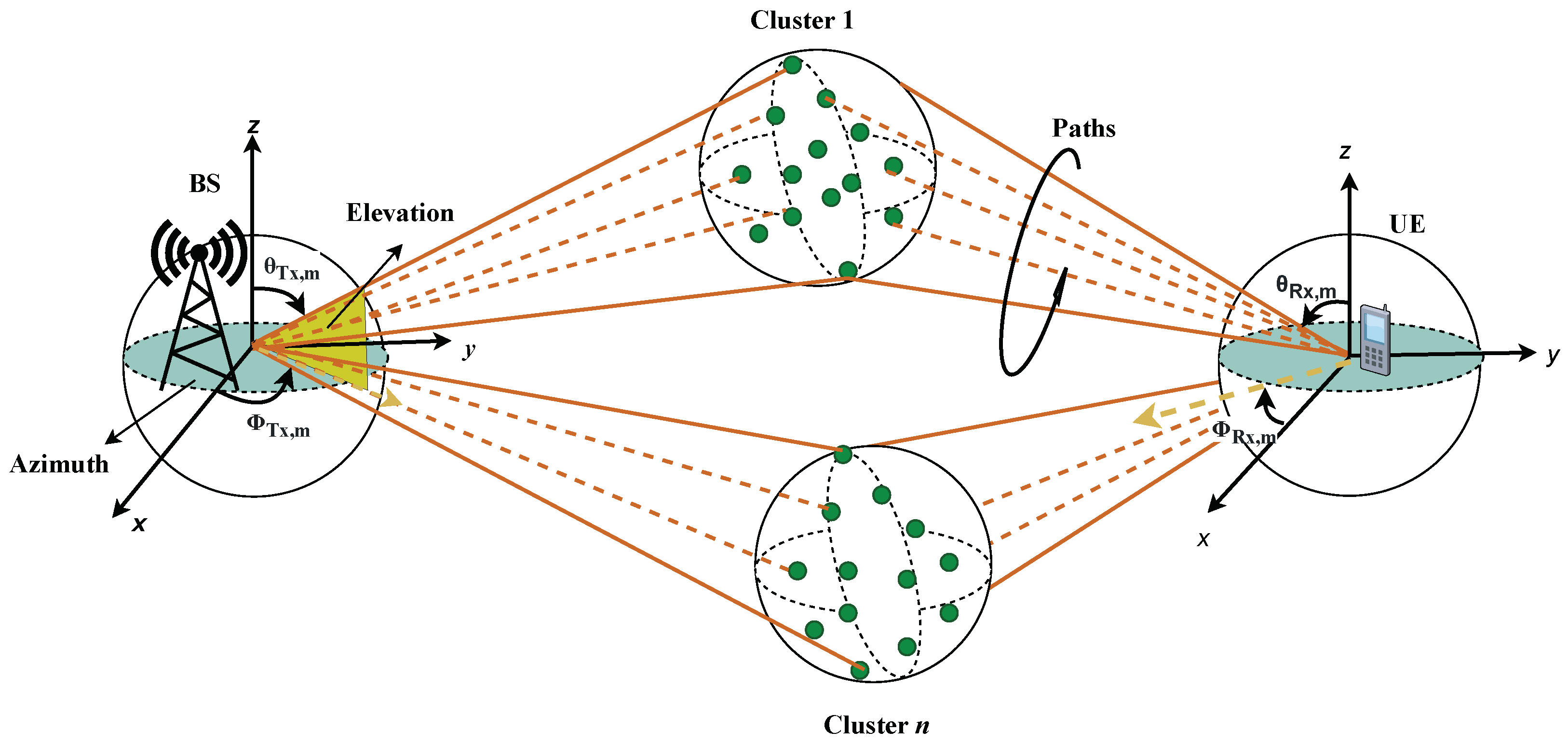
3. The 3GPP Channel Model for 5G NR

Currently, 5G mobile networks have a high device and base station density, low latency, and high data rates. MIMO channels and multi-antenna transmission increase radio link reliability and efficiency. Additionally, Two-dimensional spatial channel models models wireless channel behavior and performance with low computational complexity [24]; however, by considering only a two-dimensional plane, they poorly capture transmission channel characteristics and limit MIMO techniques to azimuth (beamforming, spatial multiplexing, and precoding). Three-dimensional channel models include channel azimuth and elevation. GSCM calculates channel parameters using randomly distributed scatterers [25].
The 3GPP specifications [12] propose an accurate and reliable stochastic channel model for building, optimizing, and evaluating 5G systems. The GSCM consists of two parts: (1) a large-scale fading model that includes path loss, line-of-sight (LOS) probability, and additional losses combined with (2) a small-scale fading model characterized by the CIR (also called “channel coefficients” in the following). In the context of multipath propagation, the received signal is composed of various attenuated replicas of the original transmitted signal. To calculate the channel coefficients, a step-by-step procedure is recommended [12] (Figure 7.5-1). A simplified representation of multipath scattering is shown in Figure 1 for the propagation of n clusters, each resolvable into m subpaths. The azimuth and elevation angles at the base station (BS) and user side are ϕ and θ . The small-scale parameters include cluster powers, delays, and arrival and departure angles in elevation and azimuth, respectively. Channel coefficients include the LOS and non-LOS (NLOS) propagation subpaths. The NLOS component is calculated as
H u , s , n , m ( t ) = P n M Power F rx , u , θ θ n , m , ZOA , ϕ n , m , AOA F rx , u , ϕ θ n , m , ZOA , ϕ n , m , AOA T RX Antenna Pattern ( F Rx ) × e j Φ n , m θ θ κ n , m 1 e j Φ n , m θ ϕ κ n , m 1 e j Φ n , m ϕ θ e j Φ n , m ϕ ϕ XPR × F tx , s , θ θ n , m , ZOD , ϕ n , m , AOD F tx , s , ϕ θ n , m , ZOD , ϕ n , m , AOD TX Antenna Pattern ( F Tx ) · e j 2 π λ 0 1 r ^ rx , n , m T . d ¯ rx , u RxLocation · e j 2 π λ 0 1 r ^ tx , n , m T . d ¯ tx , s TxLocation · e j 2 π λ 0 1 r ^ rx , n , m T . v ¯ t Doppler Component S p e e d V e c t
where F rx , u , θ , and F rx , u , ϕ are the field patterns of the uth element of receiving antenna in the direction of the spherical basis vector, F tx , s , θ , and F tx , s , ϕ are the field patterns of the sth element of transmitting antenna, ( θ , ϕ ) α , β , γ are the elevation angles γ for ray β in cluster α , and r ^ and d ^ are the spherical unit vector and location vector of antenna elements rx , tx , respectively. Similarly, r ^ tx , n , m is the spherical unit vector with azimuth departure angle ϕ n , m , AOD and elevation departure angle θ n , m , ZOD , and XPR is the cross-polarization power ratio matrix. Rays from the same cluster have identical power levels, denoted by P n . The LOS component of the CIR is calculated as in Equation (2).
H u , s , 1 ( t ) = F rx , u , θ θ LOS , ZOA , φ LOS , AOA F rx , u , φ θ LOS , ZOA , φ LOS , AOA T × 1 0 0 1 × F tx , s , θ θ LOS , ZOD , φ LOS , AOD F tx , s , φ θ LOS , ZOD , φ LOS , AOD S p e e d V e c t L O S · exp j 2 π d 3 D λ 0 exp j 2 π r ^ rx , LOS T . d ¯ rx , u λ 0 exp j 2 π r ^ tx , LOS T . d ¯ tx , s λ 0 exp j 2 π r ^ rx , LOS T . v ¯ λ 0 t C l u s t e r V e c t L O S
The Doppler frequency component depends on the UE speed v with velocity vector v ¯ , arrival angles (AOA, ZOA), travel elevation angle θ v , and azimuth angle ϕ v
v n , m = r ^ rx , n , m T . v ¯ λ 0
The CIR can be expressed as the sum of the LOS channel coefficient and the NLOS channel impulse response as
H u , s ( t ) = H u , s , 1 ( t ) L O S + n = 1 N m = 1 M H u , s , n , m ( t ) N L O S
In communication over the wireless channel, a transmitted signal x ( t ) arrives at the receiver with a time delay of x ( t τ ) . The received signal comprises multiple reflections or refraction, resulting in identical duplicates of the originally transmitted signal.
y ( t ) = x ( t τ ) H u , s ( t , τ )
This represents the convolution of the CIR and the transmitted signal, i.e., an finite impulse response (FIR) filter where the CIR represents the set of coefficients, and can be rewritten as
y ( t ) = ( x H ) ( t )
where ⊛ denotes convolution.
User equipment (UE) spatial coordinates in a 3D space affect the CIR. Mobile devices require continuous location calculations, so this variability is critical. This model uses delays and ray mapping from [12] (Table 7.5-5). To test the channel model, we used the values in Table 1.
The total execution time to compute these coefficients and the respective speedup over the CPU baseline are reported in Section 6.
Cluster-delay line (CDL) serves as a modeling tool in scenarios where the received signal comprises several delayed clusters. Each cluster is composed of multipath components that share a common delay, albeit exhibiting slight variations in angles of departure and arrival. Various CDL profiles have been defined by 3GPP for link-level simulations. For NLOS, three CDL profiles, namely, CDL-A, CDL-B, and CDL-C, are defined and CDL-D and CDL-E are constructed for LOS clusters.

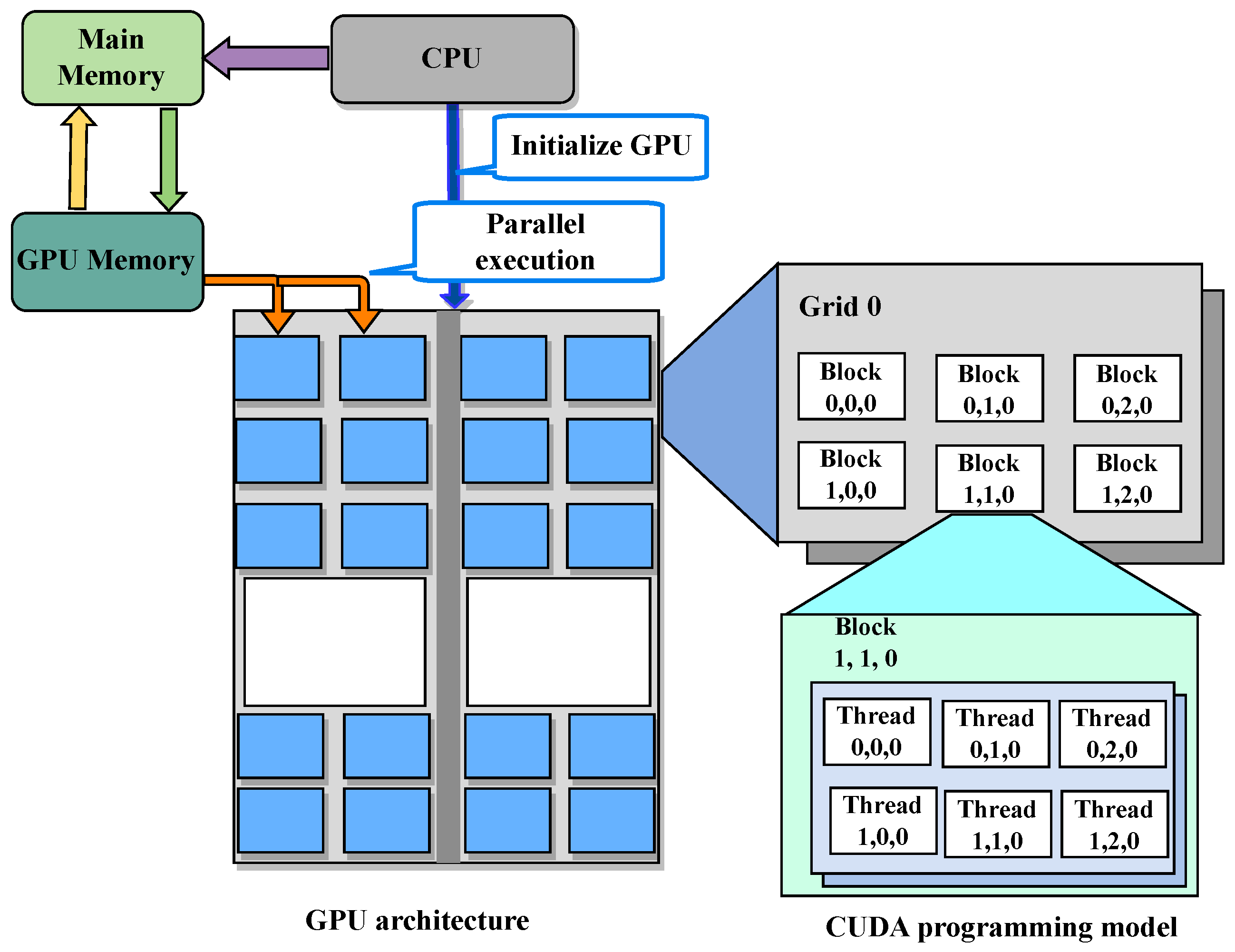
4. GPU-Based Acceleration Using NVIDIA CUDA

GPUs are a type of single-instruction-multiple-data (SIMD) architecture where the same instruction is executed repeatedly on different data in parallel. GPUs are specifically designed to run thousands of threads in parallel for higher throughput and use multi-threading to hide memory latency. Efficient management of GPU resources can be achieved through high-level programming languages based on the underlying computing architectures, resulting in improved performance.
Popular parallel computing architectures in the industry include the Open Computing Language (OpenCL) [26], Open Multi-Processing (OpenMP), and CUDA [27], a parallel programming language for managing computations on NVIDIA GPUs. Several code optimization techniques, both generic to GPU code and specific to CUDA, are required to efficiently utilize the on-chip resources and increase the overall performance.
CUDA-based acceleration code consists of two components: the host code, which runs on the general-purpose CPU and is responsible for memory and device management and a collection of functions called the kernel code, which runs on the GPU accelerator device.
Threads in CUDA are the units of computation and are modeled as functions in the kernel code. They are completely concurrent unless synchronized by the hardware or by the designer. In order to efficiently map threads to the architecture of the GPU, they are arranged in 3D clusters called blocks. These clusters are then combined into a 3D grid. The CUDA programming model groups a set of 32 threads into a single entity known as a warp. Concurrent threads (1) within a warp are automatically synchronized in lockstep by the hardware, whereas (2) threads within a block can be synchronized via barriers by the designer, e.g., to enable all threads to complete data transfers before starting a computation on those data, and (3) thread blocks cannot be synchronized with each other at all.
When a designer has to port an application that was originally written for a CPU to a GPU, the code must be completely restructured to explicitly expose parallel computations and optimize memory accesses, as the implicit optimizations provided by compilers are usually insufficient.
GPU architecture for acceleration and CUDA programming model prospective of GPU are shown in Figure 2.
The main characteristics of the GPU programming languages, and of CUDA in particular, are discussed below:
  • Allocating arrays to explicit levels in the memory hierarchy.
  • Explicitly modeling concurrency via threads.

4.1. Thread Synchronization

Explicit designer-driven thread group synchronization via barriers is the most commonly used synchronization mechanism between otherwise independent threads. It allows, for example, kernel code to transfer data between (1) large and slow off-chip memory and (2) smaller and faster on-chip memory, ensuring that:
  • All threads involved in a concurrent set of memory transfers, where each thread copies one or a few words of a large off-chip memory buffer to an on-chip memory one, are finished when computations using the transferred data begin,
  • All threads performing parallel computations are finished when the results begin to be transferred back from on-chip memory to off-chip memory.
Implicit automatic thread synchronization occurs in programs with divergent control flows, i.e., where conditional branches in the code may have different outcomes for different threads in a warp. Programmers must carefully consider using conditionals (if–then–else and switch statements) in kernel code, because it may cause significant performance losses in a GPU architecture. If a thread has two nested if–then–elses, and the conditions are independent, then typically only 25% of each GPU processor can be exploited, because all four combinations of the condition values must be executed in sequence, rather than in parallel.
As mentioned above, the CUDA programming model employs three types of thread parallelism:
  • Parallelism between thread blocks, where synchronization is impossible;
  • Parallelism within a thread block, where synchronization can be requested by the designer;
  • Parallelism within thread warp, where synchronization is automatically ensured by the GPU hardware.
From a hardware perspective, there are three execution hierarchies: cooperativethread-array (CTA) (also known as streaming multiprocessor (SM)), warp, and SIMD lanes. At kernel startup, each thread block is assigned to a CTA and each thread is assigned to a SIMD lane. If the block-level explicit synchronization barriers are used, then the CTA hardware will wait for all threads in a block to reach the barrier before any thread is allowed to continue beyond it. Using the warp-level synchronization feature of the CUDA cooperative thread array, threads are synchronized only at the warp level, and other warps can continue to execute. This is especially important in our case, because we can map elements in a cluster to threads in a warp and partitioned block into tiles of size equal to warp size. Because each cluster is modeled independently, we can synchronize threads at the warp level and avoid frequent block-level synchronizations.

4.2. Register-Based Parallel Reduction

This programming technique allows a thread to read a register directly from another thread within the same warp and allows them to exchange or broadcast data among each other very efficiently. The idea of parallel reduction is illustrated in Figure 3.
Where the __shfl_down() CUDA instruction calculates the source and the destination of each reduction step, so that in N steps 2 N data elements are reduced via an associative operation (e.g., addition) within a warp, without the need for expensive explicit synchronization barriers (i.e., the maximum value of N for which this can be performed with warps of size 32 is 5). The final stage of reduction, beyond the five iterations supported by a warp, is performed less efficiently in shared or global memory for all warps belonging to the same block via explicit barrier synchronization. These two kinds of reduction are both exploited in our model to optimize the final accumulation of the results computed by each warp to generate the total CIR.

4.3. Global Memory

Global memory is the off-chip dynamic RAM (DRAM) available on the GPU board, and it is typically separate from the CPU memory. It is used as a communication buffer for large amounts of data between the CPU and the GPU. It has high latency and relatively low bandwidth, similar to a CPU, compared with lower levels of the hierarchy. The host code is in charge of transferring data between the host memory space and the global memory. Arrays (less frequently scalars) allocated in global memory must be tagged as __device__ in CUDA.

4.4. Shared Memory

Shared memory is an on-chip memory with low latency and very high bandwidth (similar to an L1 cache), local to each streaming multiprocessor and accessible only by threads in the same block. Developers must explicitly specify shared memory data, using the __shared__ storage attribute to allocate arrays in shared memory, and move data between global and shared memory using kernel code. In our work, threads compute the channel response for each transmitter–receiver antenna port in a cluster and require repeated reading of the input data (1). Because the CUDA global memory is not fast enough to provide data to all processing elements, a two-step loading mechanism is used. First, the input data are loaded into the on-chip shared memory in a coalesced fashion, and then the data are accessed for CIR computation.

5. Channel Emulator Acceleration on GPU

The channel model output computation is a set of FIR filters, one per path. Consequently, the sampled signal at the receiver can be expressed as the sum over paths of a convolution between the taps of this FIR filter and the channel model input signal. In this study, we used a two-kernel acceleration:
  • A less computation-intensive kernel computes the FIR coefficients, i.e., the CIR, according to (4). Its pseudocode is shown in Listing 1.
  • A more computation-intensive FIR kernel that applies the coefficients to each input symbol, as in Equation (6). Its pseudocode is shown in Listing 2.
In addition to the two kernels, our accelerator also includes a host code that is written in C++ and executed on the host CPU. It is responsible for interacting with the simulation clients via sockets, performing preliminary model configurations and data transfers with the GPU.
The architecture of the proposed accelerated channel model is shown in Figure 4.
Listing 1. CUDA calcCIR kernel.
Electronics 12 03214 i001
Listing 2. CUDA applyFIR kernel.
Electronics 12 03214 i002
It uses CUDA cooperative groups to eliminate the need for block-level synchronization, because each cluster is computed independently. For efficient use of GPU resources, the long chain of computations is split into parts as shown in Listing 1 where the S p e e d V e c t and C l u s t e r V e c t are computed in shared memory. This allows threads to remain active because there is no penalty for context switching. The register-based warp-wise parallel reduction in FIR taps helps improve latency and resource utilization.

6. Results and Discussion

The baseline CPU performance was determined using an Intel Core i7-6900K @3.2GHz CPU. The baseline channel model is implemented in C++ and runs as a MEX C++ function within a MATLAB R2021a environment. The performance of the channel model is evaluated using the benchmark values in Table 1. To evaluate the performance for link-level simulations, we consider two CDL profiles, i.e., CDL-B for NLOS clusters and CDL-D for LOS clusters. Figure 5 illustrates various MIMO antenna element configurations for single-polarized antennas in Figure 5a,b and dual-polarized arrays in Figure 6c,d on transmitter and receiver end for CDL-B profile. Similarly, the same is reported for CDL-D in Figure 6 where Figure 6a,b show antenna patterns for single-polarized arrays and Figure 6c,d illustrate dual-polarized antennas on transmitting and receiving end.
The accelerator discussed in this paper was developed using the CUDA development tools [27], targeting the NVIDIA GeForce GTX 1070 GPU [28] which features 1920 CUDA cores, 120 texture mapping units (TMUs), 1.5 MB of shared memory, 4 MB of local memory, 8 GB of GDDR5 memory, and 15 SMs.
We compare the performance of the GPU accelerator with an FPGA implementation [19], which was developed using the Vitis Unified Software Platform [29] for the AMD Alveo U280 [30]. The FPGA used in [19] is based on the same 16 n m technology node as the GPU and contains 9024 digital signal processing (DSP) blocks, 41 MB of on-chip static RAM, 1,303,680 look-up tables, and 8 GB of high bandwidth memory (HBM2). Thus, its computational power is comparable to that of the GPU used in this work, because (1) a DSP unit can be used to implement a single-precision (SP) multiply and add, and (2) in [19] are used only 1/3 of the total FPGA resources so that the kernel can fit on one chiplet to avoid routing problems.
The primary goal of this work is to reduce the overall execution time of the channel model under resource constraints. We report the achieved performance for the kernels in Listings 1 and 2 on GPU platforms. To analyze the performance for both LOS and NLOS scenarios, we consider CDL-B and CDL-D profiles and uplink and downlink connection types (Table 2 and Table 3). Table 2 reports the execution latency for various combination of R x and T x antenna elements considering NLOS clusters in CDL-B profile for the parameters listed in Table 1.
Figure 7 illustrates a comparison of link-level simulation latency on CPU and GPU platforms in the two CDL profiles. The values on the horizontal axis represent the number of receiving and transmitting antenna elements, whereas the vertical axis denotes the total execution time in logarithmic scale. It can be inferred from Figure 7 that the GPU implementation greatly reduces the simulation time and enables the network planners to simulation more complex propagation scenarios with higher Doppler shift and even more antenna elements.
To analyze the effect of both transferring larger amounts of data (64 bits vs. 32 bits per value) and performing computations with greater precision, the accelerators were designed for both double-precision (DP) and SP on both acceleration platforms.
Table 4 reports the achieved performance and energy consumption for FPGA and GPU acceleration platforms for CDL-B delay profile. Overall, the optimizations result in a large speedup of 240× in comparison to the baseline CPU implementation. The achievable performance is memory bound due to the limited on-chip shared memory of the GPU, hence the need to repeatedly read large amounts of data from the DRAM rather than storing it on-chip as was performed on the FPGA.
For power analysis, CPU results are calculated based on its thermal design power (TDP) because we have no way to measure its power consumption in real time. Energy consumption is very high due to high execution latency on CPU platform. The energy consumption of the FPGA is lower than that of the GPU because the data are copied only once into on-chip buffers (our FPGA has more on-chip memory than our GPU). The DP version consumes more power in both cases due to more data being copied from DRAM and higher execution latency due to both memory access and on-chip computation. The GPU and FPGA power consumption is measured using the respective runtime support. In both cases, they are lower than their respective TDPs because only one-third of the on-chip compute resources were utilized due to memory bandwidth constraints, as shown in Table 5.
Table 5 reports resource usage for the acceleration platforms. For the FPGA, only one of the three chiplets (also called SLRs) in the package was used to achieve a good clock period.

Coding Style: CUDA vs. HLS

Although both FPGA and GPU provide parallel computation, writing source code to efficiently program them is very different. In the case of GPU, it is necessary to explicitly exploit the multi-threaded nature of the platform by exploiting the three-dimensional parallel loop structure of the thread blocks, as shown in Listings 1 and 2 (note the absence of any explicit loop construct). On the other hand, the accelerated code for the FPGA is actually more similar to the CPU version, with only the addition of (1) loops to transfer data from DRAM to on-chip memory, and (2) loop pipelining, loop unrolling, and array partitioning directives to expose parallelism in the computation and memory architecture in a form appropriate for HLS.

7. Conclusions

In this paper, we have presented an efficient implementation of a 3GPP 3D channel simulation model for GPU platforms, using various CUDA optimization techniques to exploit the parallelism and memory hierarchy of the GPU. The channel model is highly parameterized and can simulate a wide range of configurations required for real-world optimized 5G network deployments. The proposed GPU accelerator can provide fast and accurate channel simulations for 5G NR network planning and optimization, reducing the simulation time by about 240× compared to a CPU-based C++ model. The degree of performance improvement is limited by the amount of on-chip memory, which limits concurrency. The GPU design also has higher single-precision performance than a previous FPGA design, but at the cost of higher power consumption. It is interesting to note that although FPGAs typically have lower floating-point performance than GPUs, in this case, the FPGA has higher performance due to the larger amount of on-chip memory used to store the data and reduce DRAM accesses, thus offsetting the lower computational performance compared to a GPU for this very memory-intensive channel model. This work demonstrates the feasibility and benefits of using GPU-based hardware acceleration for 5G NR channel model simulations, and provides a valuable tool for network designers and researchers. Future work could include extending the channel model to support more propagation scenarios and antenna configurations, as well as integrating the channel model with other components of the 5G simulation stack, such as physical layer and link layer models.

Author Contributions

Conceptualization, N.A.S., L.L. and M.T.L.; Methodology, N.A.S.; Software, N.A.S.; Validation, N.A.S.; Formal analysis, N.A.S.; Resources, N.A.S.; Data curation, N.A.S.; Writing—original draft, N.A.S.; Writing—review & editing, L.L. and M.T.L.; Visualization, N.A.S.; Supervision, R.Q., L.L. and M.T.L.; Project administration, L.L.; Funding acquisition, R.Q. All authors have read and agreed to the published version of the manuscript.

Funding

This work was partially supported by the European Union under the Italian National Recovery and Resilience Plan (NRRP) of NextGenerationEU, partnership on “Telecommunications of the Future” (PE00000001—program “RESTART”).

Data Availability Statement

Not applicable.

Conflicts of Interest

The authors declare no conflict of interest.

Abbreviations

2Dtwo-dimensional
2D-SCMtwo-dimensional spatial channel model
2Gsecond-generation
3Dthree-dimensional
3GPP3rd Generation Partnership Project
5Gfifth-generation
5G NRfifth-generation new radio
ASICapplication-specific integrated circuit
CIRchannel impulse response
CPUcentral processing unit
CTAcooperative-thread-array
CUDAcompute unified device architecture
FIRfinite impulse response
ITUInternational Telecommunication Union
DPdouble-precision
DRAMdynamic RAM
DSPdigital signal processing
FPGAfield programmable gate array
GPUgraphics processing unit
GSCMgeometry-based stochastic model
HLShigh level synthesis
LOSline-of-sight
MIMOmultiple-input multiple-output
NLOSnon-LOS
SIMDsingle-instruction-multiple-data
SMstreaming multiprocessor
SPsingle-precision
SSPsmall-scale parameter

References

  1. Mort, G.S.; Drennan, J. Mobile Communications: A Study of Factors Influencing Consumer Use of m-Services. J. Advert. Res. 2007, 47, 302–312. [Google Scholar] [CrossRef] [Green Version]
  2. Saxena, A.; Yadav, R. Impact of mobile technology on libraries: A descriptive study. Int. J. Digit. Libr. Serv. 2013, 3, 1–13. [Google Scholar]
  3. Castleman, W.A.; Harper, R.; Herbst, S.; Kies, J.; Lane, S.; Nagel, J. The impact of mobile technologies on everyday life. In Proceedings of the CHI’01 Extended Abstracts on Human Factors in Computing Systems, Seattle, WA, USA, 31 March–5 April 2001; pp. 227–228. [Google Scholar]
  4. Wang, D.; Xiang, Z.; Fesenmaier, D.R. Smartphone use in everyday life and travel. J. Travel Res. 2016, 55, 52–63. [Google Scholar] [CrossRef]
  5. Riviello, D.G.; Di Stasio, F.; Tuninato, R. Performance Analysis of Multi-User MIMO Schemes under Realistic 3GPP 3-D Channel Model for 5G mmWave Cellular Networks. Electronics 2022, 11, 330. [Google Scholar] [CrossRef]
  6. Cisco Systems, Inc. Cisco Global Cloud Index: Forecast and Methodology, 2012–2017; Technical Report; Ciso: San Jose, CA, USA, 2013. [Google Scholar]
  7. Zhang, L.; Ijaz, A.; Xiao, P.; Quddus, A.; Tafazolli, R. Subband filtered multi-carrier systems for multi-service wireless communications. IEEE Trans. Wirel. Commun. 2017, 16, 1893–1907. [Google Scholar] [CrossRef] [Green Version]
  8. Sector, I.R. Guidelines for Evaluation of Radio Interface Technologies for IMT-2020; Technical Report; International Telecommunication Union: Geneva, Switzerland, 2017; Available online: https://www.itu.int/pub/R-REP-M.2412-2017 (accessed on 2 June 2023).
  9. Liu, L.; Oestges, C.; Poutanen, J.; Haneda, K.; Vainikainen, P.; Quitin, F.; Tufvesson, F.; De Doncker, P. The COST 2100 MIMO channel model. IEEE Wirel. Commun. 2012, 19, 92–99. [Google Scholar] [CrossRef] [Green Version]
  10. Weiler, R.J.; Peter, M.; Keusgen, W.; Maltsev, A.; Karls, I.; Pudeyev, A.; Bolotin, I.; Siaud, I.; Ulmer-Moll, A.M. Quasi-deterministic millimeter-wave channel models in MiWEBA. EURASIP J. Wirel. Commun. Netw. 2016, 2016, 84. [Google Scholar] [CrossRef] [Green Version]
  11. Nurmela, V.; Karttunen, A.; Roivainen, A.; Raschkowski, L.; Hovinen, V.; Ylitalo, J.; Omaki, N.; Kusume, K.; Hekkala, A.; Weiler, R. Deliverable D1.4 METIS Channel Models. ICT-317669-METIS/D1.4 ver 3. 2015. Available online: https://www.google.co.uk/url?sa=t&rct=j&q=&esrc=s&source=web&cd=&ved=2ahUKEwjj9eGsmqmAAxXYVPUHHem7Ak4QFnoECBEQAQ&url=https%3A%2F%2Fmetis2020.com%2Fwp-content%2Fuploads%2Fdeliverables%2FMETIS_D1.4_v1.0.pdf&usg=AOvVaw3ZtN0bJnmB4SaDFS6WSXOZ&opi=89978449 (accessed on 9 July 2023).
  12. ETSI. 5G; Study on Channel Model for Frequencies from 0.5 to 100 GHz (3GPP TR 38.901 Version 16.1.0 Release 16); ETSI: Sophia-Antipolis, France, 2020; Available online: https://portal.3gpp.org/desktopmodules/Specifications/SpecificationDetails.aspx?specificationId=3173 (accessed on 2 June 2023).
  13. Sun, S.; MacCartney, G.R.; Rappaport, T.S. A novel millimeter-wave channel simulator and applications for 5G wireless communications. In Proceedings of the 2017 IEEE International Conference on Communications (ICC), Paris, France, 21–25 May 2017; pp. 1–7. [Google Scholar]
  14. Jaeckel, S.; Raschkowski, L.; Wu, S.; Thiele, L.; Keusgen, W. An explicit ground reflection model for mm-wave channels. In Proceedings of the 2017 IEEE Wireless Communications and Networking Conference Workshops (WCNCW), San Francisco, CA, USA, 19–22 March 2017; pp. 1–5. [Google Scholar]
  15. Ju, S.; Kanhere, O.; Xing, Y.; Rappaport, T.S. A millimeter-wave channel simulator NYUSIM with spatial consistency and human blockage. In Proceedings of the 2019 IEEE Global Communications Conference (GLOBECOM), Waikoloa, HI, USA, 9–13 December 2019; pp. 1–6. [Google Scholar]
  16. Jaeckel, S.; Raschkowski, L.; Burkhardt, F.; Thiele, L. Efficient sum-of-sinusoids-based spatial consistency for the 3GPP new-radio channel model. In Proceedings of the 2018 IEEE Globecom Workshops (GC Wkshps), Abu Dhabi, United Arab Emirates, 9–13 December 2018; pp. 1–7. [Google Scholar]
  17. Pessoa, A.M.; Guerreiro, I.M.; Silva, C.F.; Maciel, T.F.; Sousa, D.A.; Moreira, D.C.; Cavalcanti, F.R. A stochastic channel model with dual mobility for 5G massive networks. IEEE Access 2019, 7, 149971–149987. [Google Scholar] [CrossRef]
  18. Hofer, M.; Xu, Z.; Vlastaras, D.; Schrenk, B.; Löschenbrand, D.; Tufvesson, F.; Zemen, T. Real-time geometry-based wireless channel emulation. IEEE Trans. Veh. Technol. 2018, 68, 1631–1645. [Google Scholar] [CrossRef]
  19. Shah, N.A.; Lazarescu, M.T.; Quasso, R.; Scarpina, S.; Lavagno, L. FPGA Acceleration of 3GPP Channel Model Emulator for 5G New Radio. IEEE Access 2022, 10, 119386–119401. [Google Scholar] [CrossRef]
  20. Abdelrazek, A.F.; Kaschub, M.; Blankenhorn, C.; Necker, M.C. A novel architecture using NVIDIA CUDA to speed up simulation of multi-path fast fading channels. In Proceedings of the VTC Spring 2009-IEEE 69th Vehicular Technology Conference, Barcelona, Spain, 6–29 April 2009; pp. 1–5. [Google Scholar]
  21. Borries, K.C.; Judd, G.; Stancil, D.D.; Steenkiste, P. FPGA-based channel simulator for a wireless network emulator. In Proceedings of the VTC Spring 2009-IEEE 69th Vehicular Technology Conference, Barcelona, Spain, 6–29 April 2009; pp. 1–5. [Google Scholar]
  22. Buscemi, S.; Sass, R. Design of a scalable digital wireless channel emulator for networking radios. In Proceedings of the 2011-MILCOM 2011 Military Communications Conference, Baltimore, MD, USA, 7–10 November 2011; pp. 1858–1863. [Google Scholar]
  23. Endovitskiy, E.; Kureev, A.; Khorov, E. Reducing computational complexity for the 3GPP TR 38.901 MIMO channel model. IEEE Wirel. Commun. Lett. 2022, 11, 1133–1136. [Google Scholar] [CrossRef]
  24. Nam, Y.H.; Ng, B.L.; Sayana, K.; Li, Y.; Zhang, J.; Kim, Y.; Lee, J. Full-dimension MIMO (FD-MIMO) for next generation cellular technology. IEEE Commun. Mag. 2013, 51, 172–179. [Google Scholar] [CrossRef]
  25. Chang, H.; Bian, J.; Wang, C.X.; Bai, Z.; Zhou, W.; Aggoune, E.-H.M. A 3D non-stationary wideband GBSM for low-altitude UAV-to-ground V2V MIMO channels. IEEE Access 2019, 7, 70719–70732. [Google Scholar] [CrossRef]
  26. Czajkowski, T.S.; Aydonat, U.; Denisenko, D.; Freeman, J.; Kinsner, M.; Neto, D.; Wong, J.; Yiannacouras, P.; Singh, D.P. From OpenCL to high-performance hardware on FPGAs. In Proceedings of the 22nd International Conference on Field Programmable Logic and Applications (FPL), Oslo, Norway, 29–31 August 2012; pp. 531–534. [Google Scholar]
  27. NVIDIA. CUDA Toolkit—Free Tools and Training | NVIDIA Developer. Available online: https://developer.nvidia.com/cuda-toolkit (accessed on 2 June 2023).
  28. NVIDIA. GeForce GTX 1070 Specifications | GeForce. Available online: https://www.nvidia.com/en-gb/geforce/graphics-cards/geforce-gtx-1070/specifications (accessed on 2 June 2023).
  29. Vitis Unified Software Platform. Available online: https://www.xilinx.com/products/design-tools/vitis/vitis-platform.html (accessed on 2 June 2023).
  30. Xilinx. Alveo U280 Data Center Accelerator Card. Available online: https://www.xilinx.com/products/boards-and-kits/alveo/u280.html (accessed on 2 June 2023).
Figure 1. Multi-path scattering in 3D channel model.
Electronics 12 03214 g001
Figure 2. GPU architecture and CUDA programming model.
Electronics 12 03214 g002
Figure 3. Parallel reduction using registers.
Electronics 12 03214 g003
Figure 4. The 3Rd Generation Partnership Project (3GPP) three-dimensional (3D) channel model on graphics processing unit (GPU).
Electronics 12 03214 g004
Figure 5. MIMO antenna configuration in CDL-B profile for NLOS clusters.
Electronics 12 03214 g005
Figure 6. MIMO antenna configuration in CDL-D profile for LOS clusters.
Electronics 12 03214 g006
Figure 7. Execution time on CPU and GPU platforms.
Electronics 12 03214 g007
Table 1. Summary of channel model emulator parameters.
ParameterValueParameterValue
Polarizations2Oversampling factor1 to 4
Elements on H-Planes4Elements on V-Planes1 to 4
Carrier Frequency ( M Hz )3600Sampling freq. ( Hz )122.88
Transmitting Antennas2 to 32Receiving Antennas2 to 32
Clusters23 (CDL-B) & 13 (CDL-D)Rays20
User Speed ( k m / h )120Subcarriers2048
Table 2. Kernel latency for a combination of MIMO elements in CDL-B NLOS.
Link TypeKernelExecution Latency
Downlink ( R x ×  T x ), Uplink ( T x ×  R x )
2 × 24 × 44 × 88 × 88 × 1616 × 162 × 324 × 32
DownlinkcalcCIR ( μ s )5.438.228.2910.9412.9320.169.2512.67
applyFIR ( m s )1.725.9511.2322.0443.1285.4222.1243.06
UplinkcalcCIR ( μ s )5.438.008.3511.1012.5819.468.8611.23
applyFIR ( m s )1.725.9311.78022.1343.8885.3224.9345.50
Table 3. Kernel latency for a combination of MIMO elements in CDL-D LOS.
Link TypeKernelExecution Latency
Downlink ( R x ×  T x ), Uplink ( T x ×  R x )
2 × 24 × 44 × 88 × 88 × 1616 × 162 × 324 × 32
DownlinkcalcCIR ( μ s )6.5611.718.6410.7211.5225.098.909.47
applyFIR ( m s )1.092.955.5611.0121.5242.1410.9021.21
UplinkcalcCIR ( μ s )8.0311.588.7410.9416.5416.067.7410.85
applyFIR ( m s )1.372.44.589.6221.7033.1612.4622.68
Table 4. Accelerated kernel latency and energy consumption.
PlatformLatencySpeedupPowerEnergy
( s )(Times)( W )( J )
CPU5.01N/A105526.0
FPGA (DP)0.0317231.10.96
FPGA (SP)0.0317229.30.79
GPU (DP)0.086052.04.37
GPU (SP)0.0224040.50.85
Table 5. Resource utilization of accelerated designs.
PlatformPrecisionMemory (%)SM (%)DSP (%)
FPGADP13.14N/A17.24
SP6.25N/A8.05
GPUDP40.8963.61N/A
SP32.2842.09N/A
Disclaimer/Publisher’s Note: The statements, opinions and data contained in all publications are solely those of the individual author(s) and contributor(s) and not of MDPI and/or the editor(s). MDPI and/or the editor(s) disclaim responsibility for any injury to people or property resulting from any ideas, methods, instructions or products referred to in the content.

