Abstract
The rapid progress of 6G mobile communication technologies has sparked a great deal research interests. The 6G core network architecture faces formidable challenges due to the escalating complexity of network service demands and diverse application scenarios. In response, our research endeavors to tackle these challenges by proposing a self-evolving architecture based on intelligent decision making. Inspired by the principles of biological morphological evolution, our architecture empowers the core network to dynamically adapt and reshape itself in order to effectively address the evolving communication environments. To facilitate this self-evolutionary process, we introduce a comprehensive framework encompassing mechanisms, architecture, agents, and algorithms that enable the network to autonomously generate and optimize its own structure, thereby ensuring adaptability to a wide range of application scenarios. By conducting concept proof simulation experiments, we have demonstrated the effectiveness of our self-evolution algorithm, which enables the 6G core network to make rational evolving decisions and exhibit remarkable adaptability to various application scenarios.
1. Introduction
With the large-scale deployment of 5G commercialization, the concept and technologies of 6G (Sixth Generation) have attracted significant attention [1,2]. The 6G mobile communication system is envisioned to be an intelligent infrastructure for universal connection of exponential growth heterogeneous devices of massive application scenarios, such as smart cities, multi-sensory extended reality, and tactile internet, etc. The goal of 6G is to establish a seamless global coverage network across space, air, oceans, and land with high transmission rate, low end-to-end latency, and customized service provisioning [1].
The 6G system primarily distinguishes itself from 5G by its endogenous intelligence capability supported by AI (Artificial Intelligence) to meet the constantly changing requirements of users and applications [3]. AI algorithms are ubiquitous from the cloud to the edge and are applied in many aspects of 6G, such as resource management, service orchestration, network security, and semantic communications [4]. However, it is still unclear how the AI can benefit the 6G core network architecture. To address this question, we review the long history of mobile communication systems and explore potential evolution strategies for the core network architecture. We further classify these evolution patterns into four basic forms: the emergence of new components [5], the elimination of obsolete functions [6], the separation or merger of different network components [7], and changes in component interactions [8]. We refer to these four forms of macroscopic network evolution as Network Morphology Evolution.
The above morphing of network components is designed and evolved by the pure manual effort of expert knowledge and industrial consensus, typically recorded in a series of 3GPP protocols, which is expensive and time-consuming. The previous generations of core networks were generally designed by domain experts under the assumption that the user’s requirements were predefined and predictable [9]. Meanwhile, the design process was often characterized by long research cycles and significant investments in manpower. The resulted fixed-defined architecture of core networks struggled to effectively accommodate the dynamic nature of evolving user demands [10]. Therefore, this design philosophy of core network architecture makes it hard to guarantee the diverse and dynamic customized 6G services anywhere and anytime.
Therefore, a 6G core network capable of automatically morphing its architecture according to the changing scenarios is promising. A 6G core network will explore new architecture without being restricted by traditional design paradigms. Intuitively, AI technology is the natural choice for automatically evolving the architecture of the 6G core network. However, to the best of our knowledge, little thought has been given to how AI can empower the 6G core network architecture with self-evolution capabilities.
Fortunately, research on simulating biological morphology evolution has emerged in the field of machine learning, providing inspiration for our idea of empowering the core network with self-evolution enabled by AI. Reinforcement Learning (RL) is a subfield of machine learning that trains agents to make decisions in an environment by maximizing a cumulative reward signal through trial-and-error interactions, enabling them to adapt and improve performance over time. Gupta Agrim et al. [11] introduced Deep Evolutionary Reinforcement Learning (DERL) to evolve diverse agent morphologies to learn challenging locomotion and manipulation tasks in complex environments. Wang Tingwu et al. [12] proposed the Neural Graph Evolution (NGE) algorithm, using Graph Neural Networks (GNNs) to describe embodied agents and simple mutation primitives to represent continuous evolution in the environment. Yuan Ye et al. [13] proposed the Transformation and Control policy (Transform2ACT) algorithm, which incorporated the design procedure of an agent into its decision-making process. Moreover, this approach enables joint optimization of agent design and control as well as experience sharing across different designs.
We consider that the evolution paradigm of the 6G core network closely resembles that of biological evolution, where the core network architecture resembles the form of a biological organism. In biological evolution, organisms evolve in response to varying environments by changing components in a three-level hierarchical structure, with cells forming tissues, and tissues forming bodies. Under the context of the 6G core network, following the idea of the SBA (Service-based Architecture) framework of 5G [14], there is thought to be a similar three-level hierarchical structure, where Microservices compose Network Functions, and the Network Functions compose the Core Network. To adapt to the changing scenarios, varying microservices can compose different network functions and then core networks. That is, the automatic decomposition and recomposition of elements at each level, triggered by the dynamic user requirements of the 6G system, provide the essential fundamental drive of self-evolution.
Similar to biological evolution, here we use the term self-evolution to refer to the intelligent capability of the 6G core network to autonomously adjust and optimize its structure in response to environmental changes during the operation process. Self-evolution enables networks to better adapt to complex and dynamic communication environments and respond quickly and accurately to different network requirements and application scenarios. The self-evolution paradigm allow the 6G core network to break the static architectures standardized by predefined protocols and to explore arbitrary novel structures beyond the known forms of human expert knowledge. In comparison to architectural research endeavors in 5G, such as Saha et al.’s comprehensive security analysis framework based on machine learning [15] for the 5G core network to enhance its security, the integration of AI in 6G is inherent rather than an externally attached module.
While self-evolution can be achieved under the principles of multiple frameworks, here we specifically adopt the idea of self-generation, which entails the network’s inherent capacity to generate novel structures to effectively adapt to emerging communication environments. As aforementioned, we consider 6G core networks as organic entities, with their network structure resembling the form of a biological organism. As shown in Figure 1, similar to how living organisms interact with the external environment, observe the environment, and choose the best body form and behavior for survival and competition, we propose an intelligent entity named Self-Evolving Agent following the basic idea of reinforcement learning for the 6G core network, aiming to actively morph the core network architecture to try to fit the changing environment by obtaining the feedback reward as much as possible. This process constitutes a closed loop for the agent of perception, reasoning, decision-making, and execution, enabling networks to autonomously learn, continuously iterate, and optimize their existing forms to meet new network requirements and challenges.
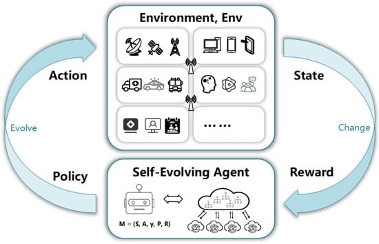
Figure 1.
Schematic diagram of 6G core network self-evolution framework based on the idea of reinforcement learning. The Self-Evolving Agent is the proposed intelligent entity that can automatically morph the 6G Core Network architecture in response to the changing user scenarios.
To further clarify the novelty of our self-evolution strategy, we review the literature on AI integrated mobile network systems. Currently, numerous research works mainly focus on the use of AI for performance optimization [16,17] in topics including wireless network resource allocation, edge computing scheduling, channel allocation, network slicing, and service chain composition. However, they generally assume that all the optimizations are conducted under the assumption that the network structure is not allowed to change. Thus, their optimization results are restricted by the given network architecture. As this type of optimization can be typically represented as a set of learnable and solvable model parameters of AI algorithms [10,18], we refer to this pattern as Network Parameter Evolution, to parallel with the aforementioned pattern of Network Morphology Evolution. While the Network Parameter Evolution tends to evolve the network at the micro-level with partial optimization in a short time span, such as seconds or minutes, the Network Morphology Evolution focuses on evolving the network at the macro-level, with global changes in a long time span, such as days, months, or even years.
In summary, we aim to empower the 6G core network architecture with self-evolution capabilities to enhance its environmental adaptability. This involves enabling the network architecture and communication protocols to support self-learning, self-generation, and self-operation and maintenance, ultimately leading to a new architecture of the 6G core network. Our primary contributions include:
- (1)
- We propose an architecture for the 6G core network that enables self-evolution based on intelligent decision making. We elaborate the core ideas and mechanisms of network self-evolution and formulate the self-evolution task for the 6G core network.
- (2)
- We propose a reinforcement learning-based self-evolving agent, which can be applied in cloud and Edge Core Networks to morph the network architecture in response to the changes of the communication environment.
- (3)
- Finally, We validate our self-evolution algorithm through experimental simulations. The results demonstrate that the self-evolution agent can make rational evolutionary decisions and enable the core network to exhibit promising environmental adaptability.
The rest of this paper is organized as follows. In Section 2, we introduce the evolution of core network architecture and discuss relevant works on Network Intelligence. In Section 3, we present the Problem Formulation for Network Self-Evolution. In Section 4, we propose the Self-Evolving Pipeline and a deployment architecture for intelligent agents in the 6G core network. In Section 5, we present the details of our algorithm. Section 6 is dedicated to the validation of our algorithm, where we conduct experiments to assess its performance. Finally, Section 7 is used to conclude our research.
2. Related Works
2.1. The Evolution of Core Networks Preceding 5G
The mobile communication system has undergone five generations of evolution, resulting in significant changes in core network architectures. For example, the 4G transitioned from the Universal Mobile Telecommunications System (UMTS) [19] to the Evolved Packet Core (EPC) [20], a pivotal change that separated the user plan and control plan, enhancing the network’s flexibility and reliability. Subsequently, the 5G core network adopted a Service-Based System Architecture (SBA) and embraced Network Function Virtualization (NFV) [21], enabling the core network to evolve and innovate while providing flexible and scalable network services and operations.
Compared to 4G, 5G has not only emerged new functional components, such as the Network Slice Selection Function (NSSF) [5], but also eliminated obsolete components, such as the circuit-switched (CS) domain, which was discontinued in the 4G EPC core network with the introduction of the all-IP network [6]. Additionally, some network components in 4G have undergone separation or have merged, exemplified by the transformation of the Mobility Management Entity (MME) in 4G. Its functions were dispersed into various network functions, such as AMF (Access and Mobility Management Function), SMF (Session Management Function), and AUSF (Authentication Server Function) in 5G [7]. Furthermore, there has been a change in the interactions between network components in 4G, as seen in the adoption of a service bus framework between multiple Network Functions (NFs) in the 5G core network control plane [8], replacing the point-to-point mechanisms utilized in the 4G EPC.These evolutionary processes reflect the continuous efforts to improve network performance, flexibility, and adaptability in response to the ever-growing demands of modern communication.While significant progress has been made in the exploration of core network evolution, there remains few valuable works that focus on self-evolution communication, similar to our research.
2.2. 6G Core Network
In comparison to the 5G core network, the 6G core network architecture should be redesigned to achieve a powerful, flexible, and intelligent network [22,23,24,25,26]. Most existing works have analyzed the challenges of the 6G communication system and proposed new architectural solutions for the 6G network [27,28,29]. Yuanzhe Li et al. [29] proposed a cognitive service architecture for the 6G core network, inspired by the nervous system of the octopus, to enhance the core network and meet the increasing quality of service requirements and complex scenarios. Xinran Fang et al. [30] introduced basic models for integrated satellite terrestrial networks. To achieve seamless global wireless signal coverage, Chao Wang et al. [31] proposed a 6G-supported space-air-ground-sea integrated network (SAGSIN) architecture. Through reconsidering the 5G Service Based Architecture (SBA) functional split, Marius Corici et al. [32] proposed a new “Organic 6G Network” concept and a new service architecture for 6G core networks based on advancements in the software services adopted. Zhang et al. [33] introduced a novel concept called “intellicise”, which describes the integration of next-generation networking technologies and AI in wireless networks. The “intellicise” network actively takes systematic entropy reduction as the global optimization objective, adaptively reshapes information systems, and ultimately endows itself with inherent intelligence and simplicity. Maier et al. [34] introduced an ESPN architecture that leverages artificial-intelligence-enhanced computing to explore the flourishing development of multisensory Extended Reality (XR) experiences within multiverse cross-reality environments in the context of 6G. Notably, Cai Lin et al. [35] proposed a Self-Evolution and Transformation (SET) architecture, where a protocol control agent is deployed in each network entity to handle flow/packet level control. This agent can assemble, configure, and exchange protocol functions, thereby enabling the protocol to change and self-evolve. However, here we specifically focus on the self-evolution within the 6G core network architecture.
Because there is still no standardized consensus on how the 6G core network would look, we adopt the hierarchical architecture proposed in [29] as the backbone of the 6G core network and follow the Service Based Architecture (SBA) as the structure organization principle of Network Function (NF). Specifically, as shown in Figure 2, the 6G core network adopts a two-layer topology with Edge Core networks and Cloud Core Networks. The Edge Core Networks sink to the edge of the network and act like a peripheral control plane for special domains or usage scenarios. The Cloud Core Network plays the role of the central brain to coordinate multiple Edge Core Networks and no longer directly participates in communication. Each layer of the core network is composed of a set of Network Functions (NF). For each NF, there is a two-level service structure. That is, the microservices serve as the fine-grained units and are then composed to form coarse-grained Network Functions (NFs), catering to diverse communication requirements. With the composition capability of different service granularity, the 6G core network would provide connectivity and support to users under various application scenarios. The integrated terrestrial, aerial, and maritime networks in 6G, built upon the foundation of terrestrial cellular mobile networks and deeply integrated with broadband satellite communications, offer extensive coverage, flexible deployment, and efficient broadcasting capabilities. To enable information exchange and sharing between different networks and to provide customized communication services to a variety of users, these networks also require seamless integration with other heterogeneous networks [36].
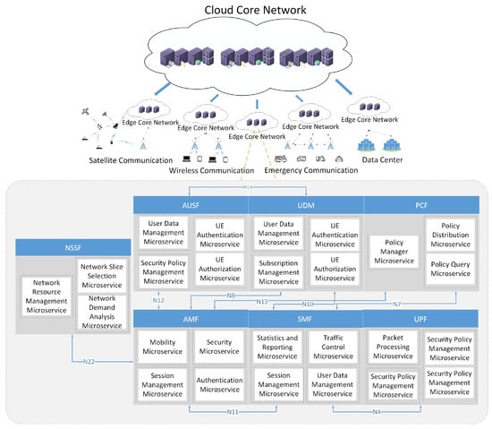
Figure 2.
Schematic diagram of the 6G core network architecture. The dashed oval box on the right depicts the Service Base Architecture of the Network Functions (NFs) in the Edge Core Network. In each NF, the two-level hierarchical structure, microservices, and NFs are also plotted.
The two-level structures of each NF in the Edge Core Network are elaborated in the right part of Figure 2. For instance, the AMF (Access and Management Function) [14] is responsible for mobility management and access control, which are composed of microservices for User Authentication, Session Management, Security, and Policy Control. For example, the Mobility Microservice is responsible for tracking the location of user equipment (UE) and managing handovers between different network cells. Similarly, the SMF (Session Management Function) [14] is responsible for efficient session management. It incorporates microservices such as Statistics and Reporting, Session Management, Traffic Control, and User Data Management. These microservices collectively contribute to ensuring smooth session establishment and maintenance. Furthermore, the AUSF (Authentication Server Function) [14] plays a crucial role in user authentication and security operations. It consists of several microservices, including UE Authentication, UE Authorization, Security Policy Management, and User Data Management. These microservices work together to authenticate users, manage security policies, and handle user-related data. Note that for each individual microservice, such as UE authentication microservices, it would be contained by different NFs. As for the NFs in the Cloud Core Network, there is yet no detailed technique solution consensus on them, thus we do not plot the NFs and microservices in the Cloud Core Network as we do for the Edge Core Network. We believe that, following the strategy of self-evolution, there is potential for the Cloud Core Network to find its optimal NF functionalities and the corresponding microservice compositions, which would be left to our future work.
2.3. Network Intelligence
With the exponential proliferation of mobile devices and data, the seamless integration and rapid development of AI and 6G have gained widespread recognition. The key characteristic of 6G is the emergence of network endogenous intelligence, often referred to as AI-enabled networks, which can perceive, analyze, and make optimal decisions autonomously [37]. Research has shown that AI-enabled 6G networks will gradually be applied to major network issues, including advanced radio interfaces, intelligent traffic control, security protection, management, and coordination [38]. Khattak et al. [39] believe that the AI-enabled 6G networks will also have significant impacts on all other related vertical fields, such as the mobile health applications supported by 6G, which will change human life. Cai et al. [40] proposed a 6G mailbox theory to enable distributed algorithm embedding for network intelligence.
The combination of AI and the network emerged earlier than the 6G era. At that time, network intelligence was primarily manifested through automatic network management and orchestration, as well as network optimization leveraging machine learning and big data analysis. As shown in Figure 3, the 3GPP working group has been promoting the standardization process of 5G Network Intelligence. R8-R10 proposed an intelligent strategy known as the Self-Organizing Network (SON) [41]. R15 introduced the 5G Network Data Analytics Function (NWDAF) and R16 defined a centralized architecture for 5G big data analysis services [42]. R17 and R18 designed a layered intelligent network architecture to further advance the application and standardization of Network Intelligence [43]. However, although these efforts have promoted the application and standardization of the industry, there is still a considerable gap between them and the true network intelligence, with limitations in deployment flexibility and scalability.
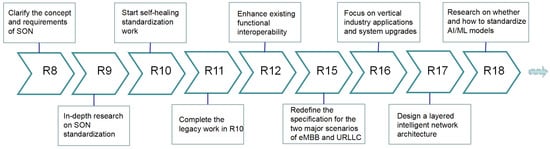
Figure 3.
Enhanced and refined diagram of Self-Organizing Network (SON) technology and standardization evolution of network intelligence.
It is obvious that the approach of utilizing AI to merely “patch” network operations and management in 5G networks is no longer viable. As mentioned in Section 1, what we need is a network agent that can learn and evolve itself according to changes in the environment. Nasralla et al. [44] and Azari et al. [45] introduced the technological evolution from 5G to 6G from different vertical fields of network applications, which laid the foundation for our thinking on the evolution of generations. Lv, Z. et al. [46] studied the evolution and prospects of network architecture and proposed a conceptual architecture for 6G networks that encompasses holistic network virtualization and network intelligence (AI).
Based on the above works, a 6G network will manifest as an intelligent agent with continuous evolutionary capabilities. Current research on the evolution architecture of the 6G core network is still in its infancy stage. There are primarily two obstacles: (1) Designing network architectures for diverse application scenarios requires extensive search space and significant computing power. (2) Evaluating the endogenous AI generated by the 6G network poses great challenges. Given the aforementioned analysis, our research focus primarily lies in establishing an intelligent network self-evolving architecture for the 6G core network.
3. Problem Formulation
To precisely and concisely describe the mechanisms of network self-evolution, in this section we formulate the task of network self-evolution as an intelligent decision-making problem based on Reinforcement Learning (RL) [47]. We first define the service hierarchy for the 6G core network. Then, we model the network self-evolution problem as a Markov Decision Process (MDP) under the RL framework. We define the fundamental concepts of the Environment and the Agent, which is targeted to learn an optimal policy to evolve the 6G core network to maximize the reward from the Environment.
3.1. 6G Core Network Hierarchy
To formulate the self-evolving architecture and mechanism, we need to define the 6G core network composition hierarchy to illustrate the three-level service structure for the Network Function (NF).
Definition 1 (6G Core Network, CN).
At time t, the 6G core network, , based on distributed core network technology, is composed of k core network subnets, , where . The term subnet here refers to the Edge Core Network and the Cloud Core Network shown in Figure 2, where we would use them interchangeably. Each subnet is independently deployed and operated, and signaling communication is allowed among the subnets through the Cloud Core Network to coordinate their behaviours. Now, we consider 3 types of evolvable elements for each subnet: the Network Function (F), the Network Protocol (P), and the subnet Topology (T). The Network Function (F) is discussed in the following definition. The Protocol (P) presents the signaling message procedures among Network Functions. The Topology (T) indicates the physical connection structure between Network Functions (F). Then, a subnet, , at time t can be represented as a set of its evolvable elements: . The subnet is regarded differently to the subnet when either of their 3 elements are different at time t. With the evolving process forward, the subnet is allowed to change to . When either subnet is changed, the core network is considered to be evolved.
Definition 2 (6G core network Functions, F).
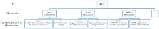
The network functionalities of the 6G core network are assumed to be divided into a set of highly reusable microservices, denoted as ; k is total number of microservices. Each microservice, ms, implements a basic and decoupled network service, such as user authentication, session establishment, etc. Multiple microservices can be recombined together to constitute the new core network functions: . When deploying the 6G core network, each network function element (NF) implements a subset of the core network functions: . For example, Figure 4 shows the constituent microservices of AMF, as well as the corresponding functions and data.
Figure 4.
Hierarchical structure of AMF. The AMF is composed of a set of microservices; each of them has its functions and data.
3.2. Self-Evolution Task Formulation
Given the definitions of the 6G core network, we formulate the self-evolution task of the 6G core network as a model of Reinforcement Learning (RL) [47]. Reinforcement Learning enables an agent to learn optimal decision-making strategies through interactions with its environment. Specifically, RL is usually modeled as Markov Decision Processes (MDPs), denoted as , where the elements in the tuple M represent the state space, action space, discount factor, transition probability function, and reward function, respectively. Starting from an initial state, , the agent iteratively samples an action, , according to its policy, , while the environment generates the next state, , based on the transition function, , and assigns a reward, , to the agent. The goal of the agent is to learn a policy, , that maximizes the expected total discounted reward: , where H is the time horizon experienced by the agent. Following the framework of RL, we define the basic elements of the self-evolution task for 6G Core Network.
Definition 3 (Environment, ENV).
The landscape of 6G core network application scenarios exhibits significant diversity. Specifically, the i-th network application scenario at time t, such as satellite or emergency scenarios, can be denoted as . Here the introduction of time t indicates the constantly changing nature of the application scenarios. The overall application scenarios, , of the 6G core network at time t can be denoted as a collection of K individual application scenarios, i.e., . The role of the Environment, , is to provide observations and rewards to the Agent to learn the evolving policy.
Definition 4 (Agent).
An Agent is an intelligent model learning the optimal evolving policy. For Cloud Core Networks and Edge Core Networks, they will deploy their own Agents to coordinately maximize the overall rewards by changing their function, F, protocol, P, and topology, T.
Definition 5 (State).
Theoretically, all the information that might drive the changes of the core network would be viewed as the State, including but not limited to the user demands, the current QoS level, microservices contained within the NFs, traffic on physical servers containing the NFs, and CPU and memory utilization of those servers. In practice, the data of State could be collected and provided to the Agent by the network management system. When considering the long-term self-evolution nature of the core network, the State prefers the statistic results over a large time span rather than the direct raw data.
Definition 6 (Action).
The Action is defined as all the legal modification selections applied to the function, F, the protocol, P, and the topology, T, of the core network. The recomposition of existing microservices, the decomposition of services into new microservices, the emergence of a new kind of NF, and the re-deployment of the NFs among physical servers are all possible instances of Action. When the Agent executes the selected actions, the Environment ENV would feedback corresponding rewards to guide the Agent to learn the optimal evolving policy.
Definition 7 (Reward).
The reward can be divided into two categories: functionality reward and performance reward. Because the evolved core network is automatically learned by the Agent instead of being produced by following the pre-standardized solution, it is not theoretically guaranteed to work as well as the human-defined one. Therefore, the functionality reward is used to measure whether the evolved core network would implement the targeted functions of the control plane. The performance reward is usually defined according to the QoS (Quality of Service), QoE (Quality of Experience), and/or operation KPI (Key Performance Indicator) benchmarks to assess the efficiency of the evolved policy. The two types of reward would be appropriately mixed to formulate the evolving goal of the Agent.
We summarize the defined symbols and list their corresponding meanings in Table 1 for convenience. Some of the symbols will be further explained in the following section.

Table 1.
Symbol Denotations.
4. Self-Evolving Pipeline
In this section, we propose a cyclical pipeline for the evolving agent to complete the endless evolution of the 6G core network. The design considerations behind the pipeline stem from insights of the biological evolution process. We posit that each subnet SCN experiences a unique environment and evolves through the intelligent modification of its genes and physical structure. In addition to the pipeline for self-evolution, we also propose a deployment architecture for the intelligent agents in the 6G core network.
4.1. Pipeline Cycle of Evolution
Figure 5 illustrates the self-evolving pipeline for the 6G core network. The pipeline is analogous to the biological evolution process, consisting of three distinct stages: (1) gene generation; (2) gene composition to construct the body; and (3) natural selection to identify the optimal composition. In this context, the gene refers to the microservice, the body is the subnet SCNs, the optimal composition is the evolved 6G core network adaptive to the given application environment, and the natural selection is the self-evolving algorithm that will be later detailed in the next section. It is important to note that due to the constantly changing environments, the three-stage pipeline will be run iteratively to maintain the adaptability of the resulting 6G core network. The period of each pipeline cycle is primarily determined by the rate of changes in the environment. For instance, when application scenarios are slowly changing over a long period of time, the pipeline might evolve once every few months or even years. On the other hand, when a new application scenario suddenly emerges, the pipeline tends to quickly modify the core network structure within days or minutes.
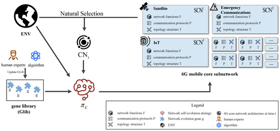
Figure 5.
Self-evolving pipeline for 6G core network. The pipeline is composed of three stages: gene generation, SCN construction for various application scenarios, and nature selection to produce a new Core Network (CN). This pipeline is continuously driven by the ever-changing environment, , through the learning of an evolution policy, . Three example of edge subnet SCN are plotted: the Satellite SCN, the Emergency SCN, and the IoT SCN. As they serve different applications, each SCN is distinct from the others in that it possesses its own network function, F, communication protocol, P, and topology, T. The cloud subnet CCN is omitted here for simplicity.
The pipeline begins with the generation of network evolution genes, the most fundamental components in a self-evolving 6G core network. These genes, also known as network microservices, serve as the building blocks for the NFs of the core network. Each gene possesses specific attributes, including its function and the data it processes. For instance, a registration microservice handles user registration requests by collecting user identification information.
There are typically two methods for generating genes: manual definition and deployment by human domain experts, or automatic extraction using machine learning algorithms from the current core network. Considering the increasing complexity of the 6G core network, it is usually beyond human ability to manually generate the microservices, thus we prefer to exploit the latter method. At each time step, t, the evolving agent automatically extracts a set of genes according to the current architecture of the 6G core network to compose the gene library, . This set is then updated to the next version, , by adding new genes or removing old ones. The in-depth details of the machine learning algorithm used for gene extraction will be discussed in the following section.
In the second stage, with the gene library, , the objective of the pipeline is to reconstruct the subnet SCN by appropriately combining genes into various functions to form a set of NFs. Specifically, given the current structure of , the evolving agent aims to learn the composing strategy, , that decides how to select the genes and compose them into special NFs, which in turn affects the overall structure of the next time-step SCNs. That is, , where is the application environment for the subnet . Different would lead to different variants of SCN, each with its own network function, F, communication protocol, P, and topology, T. For a given , the corresponding strategy, , would produce a group of individual microservice composition plans, analogous to the concept of population in the process of natural selection.
In the third stage, the pipeline evaluates the fitness of each individual SCN plan and selects the most suitable one for survival. The evolving agent assesses the composed SCN by assigning corresponding rewards based on metrics such as evolutionary success rate, evolutionary speed, service performance, and resource costs. The evolutionary success rate measures the completeness of the evolved core network’s required functionality. The evolutionary speed evaluates the response time from changing the environment to the convergence time of the evolutionary strategy. Service performance and resource cost are usually used together to measure the trade-off decided by the evolution policy.
With these rewards, the pipeline repeatedly optimizes the gene library, , the gene composition plan for SCNs, and the agent evolution policy. Once convergence is achieved, the newly produced architecture of the 6G core network is deployed to replace the old one, completing a cycle of evolution.
4.2. Deployment Architecture of Pipeline
After discussing the working stages of the pipeline, we propose a distributed architecture to deploy the evolving agent. As depicted in Figure 6, the 6G core network hierarchy comprises a Cloud Core Network (CCN) and multiple Edge Core Networks (ECNs), each catering to customized communication scenarios. The CCN is responsible for managing and coordinating ECNs and does not directly involve the processing of user requirements.
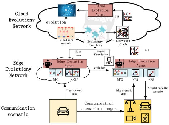
Figure 6.
The hierarchical architecture of the self-evolution pipeline for 6G core networks.
At the top-layer of the architecture, the central CCN deploys AI models as its cloud evolving agent. This cloud agent is responsible for gathering information about itself and all ECNs to learn the evolving policy for the CCN. It creates training data and updates its evolving policy to maximize rewards, ensuring that the CCN evolves in line with its agent’s decisions. To optimize resource sharing and reuse the microservices among all ECNs, it is feasible to deploy only a single global gene library, , in the CCN. The CCN’s agent is responsible for creating, maintaining, and updating the to ensure that all the ECNs can efficiently access and utilize the shared microservices. By doing so, the self-evolving architecture can achieve greater scalability and consistence while minimizing resource consumption. To enhance the intelligence of the cloud agent and ensure automatic maintenance of the , a knowledge graph is often deployed in the CCN, which incorporates domain expert prior knowledge and the evolving preferences of 6G service operators. This allows the cloud agent to learn from the experts’ insights and make informed decisions about how to evolve the network. By incorporating this knowledge into its evolving policy, the cloud agent can improve its performance and help the CCN evolve more efficiently. For instance, we can construct a knowledge graph with the entities and the relationships containing knowledge of 3GPP protocols, Cloud Evolution Agent, and the statistics of the CCN to reduce the decision space of the CCN evolution.
At the bottom-layer of the architecture, there are multiple ECNs designed for various application scenarios. Each ECN is equipped with its own evolving agent, which receives edge data, such as the signaling throughput, the distribution of various signaling types, and quality of service (QoS) of UEs and is responsible for making decisions about how to evolve its host ECN. Specifically, the edge agent learns how to use the genes from the global gene library, , residing on the CCN, to compose desirable network functions. The significant changes in the architecture of numerous ECNs will result in changes to the environment of the CCN, such as signaling throughput of the ECN and signaling distribution of the ECN. Changes in environment will result in alterations to the composition of microservices, and thereby evolute the CCN on NFs, and then the Edge Core Network structure. As the application scenario of the ECN changes, as shown in Figure 6, where the applications expand from single autonomous vehicles to a mixture of services including autonomous vehicles, video surveillance, and Internet of Things (IoT), the agent decides to reshape the structure of the ECN from two NFs into three NFs, while also altering the internal microservice compositions of each NF. In the long-term, the evolving policies of different agents will be highly distinct due to their ECNs serving different application scenarios. As a result, the architecture of the ECNs will also vary accordingly. The significant changes in the architecture of numerous ECNs will result in changes to the environment of the CCN, such as signaling throughput of the ECN and signaling distribution of the ECN. Changes in environment will result in alterations to the composition of microservices, and thereby evolute the CCN.
In the hierarchical self-evolution architecture of the 6G core network, the agents in the ECNs and CCNs form a distributed multi-agent system, which means that the evolving policies learned by each agent are not generally independent of others. Due to the complexity of joint decision making among all agents, although there have been valuable reinforcement learning algorithms for multi-agent systems published in the literature, we leave this work for further research. To streamline the deployment process for the evolving agent, the MLops (Machine Learning Operations) techniques would be employed to support agent development, deployment, and operation. In the context of this paper, the agents would prefer to utilize the RL (Reinforcement Learning) framework and associated algorithms to make decisions for the 6G core network evolution. Because the agent is natively integrated into the core network, it offers a distinct advantage over external AI solutions for the current 5G core network in terms of comprehensive state perception, real-time decision-making, economic interaction, and efficient resource utilization.
5. Self-Evolving Algorithm
As shown in Section 4.1, the self-evolving pipeline is composed of three stages from the genetic and evolutionary point of view. In this section, we will provide a clear definition of the three stages from the perspective of algorithm modeling and detail the specific methods for each stage: (1) GLib Generation Stage; (2) Composition Stage; (3) Evaluation Stage.
5.1. Formulation of Self-Evolving Pipeline
As mentioned in Section 3.2, we formulate the Self-Evolving Process of the 6G core network as a framework of Reinforcement Learning, which is usually modeled as a Markov Decision Process (MDPs): . In particular, each stage, , of the pipeline is modeled as an individual MDP. On the one hand, they have different action spaces and different strategies. On the other hand, each stage is closely related to one another, together forming a self-evolving cycle, .
(1) GLib Generation Stage: At stage , the agent applies actions, , to manually generate microservices by splitting the core network functions into reusable building blocks, and then updates the with the newly extracted microservices. The strategy, , in this stage makes action selection based on the current environmental information, , and gene pool, .
(2) Composition Stage: At stage , the agent applies action, , to select existing microservices from the , which is updated in stage , and combines them into network elements based on the strategy, . The output of stage = 1 for each SCN is a set of candidate microservices compositions, constructed by adding or reducing microservices to existing , also with connections between to generate static network topology. It is important to note that, at this stage, the agent does not need to directly interact with the application environment.
(3) Evaluation Stage: At stage , the agent applies actions, , to organize the obtained and network topology deduced from stage into a service function chain for its host SCN, and then evaluate arrangement performance by interacting with the environment, . The strategy for achieving the above goals is called .
It is important to note that the time scale, t, in our algorithm is different from the commonly used training scale, which may represent a long time range. So the update of network policy is not real-time. At each time step, t, represents all environmental information of the current application scenarios, overall network latency, and CPU and memory usage of . The policy of the Self-Evolving agent is denoted as below.
In order to prevent human intervention in network evolution, we do not set reward functions in stages and , and only interact with the application environment in the stage , which will be helpful to fully evaluate the completion of specified tasks by self-evolving networks. The detailed explanation of the reward function will be provided in Section 5.3.
After we formulate the self-evolving task of the core network, the learning of the optimal evolving policy, , for the agent would be accomplished by popular RL algorithms. Here, we employ Proximal Policy Optimization (PPO) [48], a popular RL algorithm based on Policy Gradient (PG). PPO is particularly suitable for our approach because it has a Kullback–Leibler (KL) divergence between current and old policies, which can prevent large changes, thus avoiding catastrophic failure.
5.2. GLib Generation Stage
The goal of generation is to decompose the Core Network Functions into multiple microservices. This approach follows the insight of decomposing monolithic software into smaller, more manageable components known as microservices [49,50]. By regarding the SCN of current time step t as a monolithic software system, we can decompose it into various microservices with distinct functionalities and corresponding data, which would be used as raw materials to compose new network elements in the second stage, . The optimal decomposition of the current SCN is learned through the reward principle of higher cohesion within the microservices and lower dependency among them, which offers advantages of easier maintenance, improved scalability, and reduced coupling risks.
In particular, we employed Go-Callviz [51] to analyze the code structure of the current core network functions. Go-Callviz is an open-source project for visualizing the call graph of the Go program, which shows the relationships between functions and methods, including which functions are called by which others and how many times each function is called. By leveraging this information, the Go-Callviz generates an intuitive graphical representation of the call graph, which serves as the input for our gene decomposition algorithm.
We denote the obtained call graph as a directed graph, , where V is a set of entities and edge, , represents the connection between entities i and j. We define three distinct types of nodes in graph G: data node (), function node (), and module node(). These nodes correspond to the primary attributes of a microservice, with the first two representing the data and functionality, respectively. The module node, on the other hand, refers to the package under analysis, and it responds to the functional correlation in the graph clustering algorithm, indicating a stronger correlation between functions within the same package. Given the three types of nodes, we define five types of directed weighted edges:
- module–function (): if a function, f, belongs to package m, then the weight of the edge , otherwise .
- function–function (): if there are calling relationships between function and , then they are connected by edge with weight, as below:where and n represents the depth of function calls. For example, if there is a function call chain , then in , while in .
- function–data (): when function has a read/write operation on data , the edge weight between them is defined as follows:where represents the maximum number of times all functions, , perform read/write operations on data node . represents the number of times function performs operations on data node .
- data–data (): The weight of edge when data is the member of data , otherwise .
- module–function (): The weight of edge when f is in package m, otherwise .
To further clarify call graph G, in Table 2 we present several examples of utilizing Go-Callviz to analyze the source code of Free5GC [52], an open-source project for 5th generation (5G) mobile core networks. Because the number of nodes obtained from Free5GC exceeds a few hundred, Table 2 only shows a few of the source and target nodes along with their respective edge connections. Note that because there are currently no popular projects for 6G core networks, we only use Free5GC for the concept proof of the self-evolution in this gene generation algorithm and later experiments.
Table 2.
Examples of nodes and edges in the calling graph of the Free5GC [52] project, where source and target refer to the nodes and relationships are the types of edges. Function nodes are represented by the function path in the source code.
The nodes in calling graph G provide the fine-grained materials to generate microservices. Generally, the extraction of microservices follows the idea of “high cohesion, low coupling”. High cohesion implies that each microservice is focused on a specific and well-defined functionality, ensuring its internal components work together effectively. Low coupling indicates that the microservices are loosely interconnected, minimizing dependencies and enabling independent development, deployment, and scalability.
To meet this principle, we propose to use the graph clustering Louvain algorithm [53] to cluster the nodes into a set of coarse-grained microservices, each of which has independent function and data. In particular, the input of the clustering algorithm is calling graph G, and each cluster output by the algorithm is treated as a microservice, that is, a gene . The clustering algorithm ensures that the resulting microservices exhibit higher coherence within them and lower coupling to one another, which aligns with the desired characteristics of being easily manageable and reusable.
In Figure 7, we present an experimental example of six clustered microservices, along with the corresponding nodes and edges in the user traffic control microservice. It is evident that the extracted microservices, such as AMF Session Management, Authentication, and SMF Session Management, are highly coherent with the function requirements of current 5G core network NFs, including AMF, SMF, and AUFS. This suggests that the clustering strategy on the calling graph of the core network is desirable for achieving the goal of gene generation.
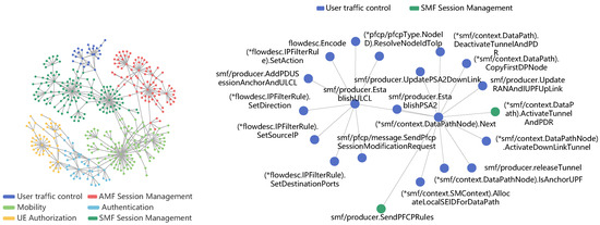
Figure 7.
An example of the clustering results for AMF, SMF, and AUSF. The left plot shows the resulting 6 microservices in different colors. The right plot zooms in on the nodes and edges in the user traffic control microservice. In the node name, the asterisk (*) along with the string enclosed in parentheses represents a pointer to the corresponding structure type.
To further quantify the quality of the obtained microservices, we use four evaluation metrics to assess them [54]: (1) Centripetal coupling (Ca): the number of other microservices that depend on the classes within a given microservice. A higher value indicates greater stability of the microservices; (2) Centrifugal coupling (Ce): the number of other microservices that the modules within a given microservices depend on. A higher value indicates a higher dependency and lower stability of the microservices; (3) Instability (I): the level of instability of microservices by calculating . , where 0 indicates the most stable microservice that does not depend on any other microservices and represents extreme instability; (4) Relational Cohesion (RC): the ratio between the number of internal relationships (function–function, data–data, function–data) and the number of functions and data within a microservice. A higher RC indicates higher cohesion within the microservice. The evaluation results of Free5GC clustering will be later shown in Section 6.3. Finally, it is noteworthy that the proposed graph clustering algorithm does not constitute a typical candidate for solving MDP problems. In this context, we consider the call graph as the state, , of the MDP, with the clustering selection of a particular node as action, , and the four evaluation metrics as local rewards, R. With this viewpoint, the policy, , is learned when the clustering algorithm converges.
5.3. Composition and Evaluation Stage
In stage , the is obtained through decomposing the Core Network Functions into multiple microservices, which are input for the next two stages. The goal of composition stage is to automatically learn how to compose microservices generated in the first stage, , into and set the connections between to form a static network topology. In the next stage, , the evolving agent organizes the obtained and network topology deduced from stage into a dynamic service function chain and then interact with the environment, , to receive feedback on a reward, . Although these two stages are modeled as relatively independent MDPs and use different methods, the and network topology generated in stage will not be evaluated separately, but as a component of the service function chain in the third stage, . It can only be regarded as the completion of a training cycle after finishing both the second and the third stages. The optimal service chain can be obtained through multiple loops of Reinforcement Learning. Therefore, we will merge the two stages together for a more comprehensive discussion.
As mentioned in Section 5.1, we model the composition task as a typical MDP. The state, , includes the gene library, , the application scenarios, , and the current set of network elements, . The agent makes decisions at each time step as to whether or not to add or remove microservices from and modify the connection topology between them, so the action set consists of three options: : Add-Microservice, which adds a microservice onto a selected network element; : Del-MicroService, which deletes a microservice from a selected network element; and : Set-Connection, which represents whether to set connections between as 0 or 1. Note that there is no direct reward function, R, at the composition stage , and we later use the reward of stage to supervise the learning of composition. As a result, policy enables rapid growth and adaptation in the network topology by generating diverse and connections between them. The microservices being composed into the same NF are integrated into more compact modules, eliminating internal interfaces and sharing data between them. This approach effectively reduces resource consumption within the .
After the composition stage, we need to evaluate whether or not the generated and static network topology can effectively complete specific tasks. Here we select the method of generating dynamic service function chains to evaluate performance. The state includes the application scenarios, , and the current set of network elements, , in stage . At each time step, t, the action traverses through existing connection relationships from the current network element and selects one network element for the next time step, . Policy encourages exploration of multiple service chain generation paths.
In dynamic environments, service composition needs to support the recovery service-based applications from unexpected violations of not only function but also QoS, and the key factor in deciding which microservices are appropriate to be combined is their ability to provide a more modular and scalable service function with high performance and efficient resource consumption. Therefore, the reward, , for evaluation takes into account two factors: (1) whether or not the composed network elements, , can form a complete SCN that meets the functional requirements of the core network; (2) whether or not the tasks are completed with high Quality of Service (QoS). In other words, , where mainly includes a reward for completing a signaling process and each step taken in the network evaluation stage. is determined by network performance, including CPU occupancy, time latency, and specific rewards for different tasks.
The pseudocode of the Self-Evolving Algorithm 1 is presented bellow. The algorithm takes the initial strategy, , network elements, , gene pool, , and the initial state of the environment, , as inputs, and then outputs an update strategy, , after completing three stages of training. In the first stage, , the self-evolving agent samples action to split microservices and update the gene pool, through policy . In the second stage, , the agent samples action to reorganize microservices to form and topologies through policy . In the third stage, , the agent samples action to generate dynamic service chains and interact with the environment, , to return reward function through policy . All parameters are stored in memory pool M, and we use Proximal Policy Optimization to update the strategy.
| Algorithm 1 Self-Evolving Algorithm |
|
6. Self-Evolution Experiment
In this section, we conducted a simplified toy experiment as proof of concept for the proposed self-evolving mechanism of a 6G core network. Because it was challenging to clearly demonstrate the evolution results when directly applying the self-evolving algorithm to the fully functional core network due to its inherent complexities, we simulated a smaller core network, based on the Free5GC [52] project, with limited functionalities and application scenarios, enabling us to conduct controllable experiments and assess the efficiency of our proposed approach. Furthermore, due to the current lack of consensus on NF structures and signaling procedures for the 6G core network, we opted to utilize the existing 5G core network as our experimental platform. In addition, for the sake of simplicity, we only simulated an Edge Core Network. The joint evolution of the Cloud Core Network and multiple Edge Core Networks was left for future work.
6.1. Application Scenarios
For the single simulated Edge Core Network, we designed two communication scenarios that served as the external environment to drive its evolution: Emergency communication and Satellite mobile communication. In the Emergency scenario, low latency of service was essential to ensure the safety of people and equipment [55]. On the other hand, in the Satellite scenario, communication had to be completed under certain resource constraints [56]. The varying demands of these two scenarios led to different outcomes for the core network’s evolution.
For the two application scenarios, as shown in Figure 8, we assigned the Edge Core Network with three tasks: user registration, PDU session establishment, and PDU session modification. Correspondingly, the involved NFs included AUSF (Authentication Server Function), UDM (Unified Data Management), PCF (Policy Control Function), AMF (Access and Mobility Management Function), and SMF (Session Management Function). Note that we also simplified the signaling message procedures of the 5G core network standardization for these three tasks to focus on understanding the evolution.
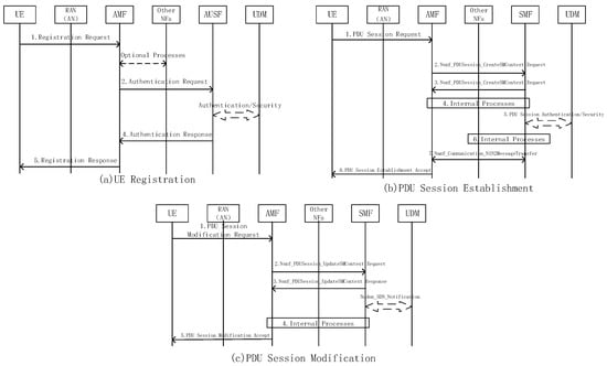
Figure 8.
Three signaling message procedures used in the experiment. The procedures are derived by removing optional procedures and consolidating non-optional procedures from the 5G standardization documents.
We further differentiated the two scenarios by setting different task parameters according to their respective characteristics. As shown in Table 3, we set the arrive rate, , of task requests, the mixture proportion of tasks, and the performance requirements for the Emergency and Satellite scenarios. We also designed a General scenario as a baseline in order to set the special performance requirements for the Emergency and Satellite scenarios. We primarily focused on the communication flows of UE registration and session establishment, assuming a ratio of 1:10:5 for UE registration, session establishment, and session modification (with session establishment being more frequent than UE registration). We initialized the simulated core network with the settings in Table 4, and the evolution pipeline was started by generating a gene library, , with these settings.
Table 3.
Simulation parameter settings for the application scenarios. is the total arrive rate of 3 task requests, proportion denotes the mix ratio of each task, and the latency/cpu occupation performance requirement is represented by Inequation to emphasize the special communication characters of the Emergency and Satellite scenarios. The General scenario here is set as a baseline with only basic communication requirements that can be met without any evolution.
Table 4.
Simulation initialization settings. In each Network Function, the related microservice and its functions and data are listed.
6.2. Experiment Settings
We used an NVIDIA TITAN 1080 graphics card and two Intel(R) Xeon(R) CPU E5-2620 v4@2.10 GHz processors (8 cores each) for our experiments. We conducted self-evolution experiments in the Gym [57] simulation environment, which is an open-source platform providing a set of tools and algorithms for creating, evaluating, and optimizing Reinforcement Learning (RL) environments. To overcome Gym’s lack of a dedicated self-evolution environment setting, we developed a custom simulation environment with User Equipment (UE), microservices, and Network Functions (NF) for self-evolution experiments. The UE serves as a mere signaling transceiver within the system. In addition, the design of our microservices and NFs draws inspiration from Free5GC’s architecture. However, in contrast to Free5GC, we have omitted the intermediate processing steps in our microservices and network functions. Instead, we focus solely on calculating performance during user interactions.
Because the first stage, , of the evolution pipeline has already been discussed in Section 5.2, in this section, we only simulated the composition and evaluation stages using the gene microservices derived from stage . The simulation environment provides state information for agent training, including message experienced latency and CPU occupation. The action spaces of stages and use the definitions in Section 5.3. The rewards, , are specified as follows:
where the agent is rewarded with when it successfully completes each of the three tasks and a penalty, , is imposed on the length of the message step of the task to encourage the agent to optimize the NF compositions in order to shorten the service chain for efficiency purposes. The reward, , is determined according to the latency and CPU occupation preferences of the three tasks. For the latency, we focus on the registration latency, , PDU session establishment latency, , and PDU session modification latency, . The total latency, , is set as part of . The registration latency is estimated as , where represents the number of microservices related to registration, is the processing latency, is the number of connection links, and is the transmission speed set to the link. The PDU session establishment latency, , and PDU session modification latency, , are calculated in a similar way to . As for the CPU occupancy, we considered the total CPU occupancy, , as a reward by adding up the respective CPU usages for each task: registration , PDU session establishment , and PDU session modification .
Furthermore, we took into account the hop number of the service chain required to finish a task as the third part of the reward, R, which encourages the agent to quickly find the shortest signaling message path in the evolved network. Therefore, the service chain lengths of the above three tasks were added together as the reward, . Thus, the total reward, R, we used in the experiment was set as:
where is a constant to ensure that the reward remains positive, and are hyperparameters to weight the three QoS factors. The agent obtains a high reward when it can complete the three tasks with lower latency, small CPU utilization, and shorter signaling service chains. The setting of reward hyperparameters are listed in Table 5.
Table 5.
Hyperparameters of reward settings. Different scenarios have different QoS reward weights corresponding to their evolution preferences. For the task completion reward, , the agent receives a positive reward of 200 when it successfully completes a task, and a negative penalty of when it fails to do so.
We employed the Proximal Policy Optimization (PPO) algorithm [48] to train the agent. The PPO network consisted of a Multi-Layer Perceptron (MLP), and the output layer utilized the softmax function to determine the action with the highest probability. The hyperparameters of the PPO model are outlined in Table 6.
Table 6.
PPO hyperparameter settings.
6.3. Experiment Results
First, we verify the quality of the generated microservices in using the metrics defined in Section 5.2. We extract in total, 57 microservices from AMF, SMF, and AUSF of Free5GC by using the graph clustering algorithm, some examples of which are shown in Table 7. It can be observed that the Mobility microservice has great stability with high . The microservices of User Traffic Control and SMF Session Management are more dependent to each other, with high , because they are extracted from the same SMF. The relative low Instability, I, indicates that the extracted microservices have high stability, and the relatively high Relational Cohesion, , suggests a well-structured and efficient microservice architecture. On average, the microservices obtained are desirable due to their relatively low coupling and high coherence.
Table 7.
Evaluation results of part of the 57 extracted microservices. Ca refers to the Centripetal coupling, Ce is the Centrifugal coupling, I is the Instability, and RC is the Relational Cohesion.
We present the results of the self-evolution algorithm for the Emergency and Satellite scenarios in Figure 9. In particular, we demonstrate the reward convergence while also displaying the changes in CPU occupancy and latency for each scenario. We can see that the algorithm can converge quickly within only 10 epochs. After that, the newly evolved core network can significantly reduce the CPU occupancy and latency. This highlights the ability of the evolving agent to automatically adapt to various scenarios by reconstructing itself. It has been observed that the reward for both scenarios exhibits some fluctuations, which may be attributed to the agent’s random exploration. For instance, during the 33rd epoch of the Emergency reward shown in Figure 9a, the agent generated an authentication NF but failed to add it as one hop into the service chain during the registration process, resulting in the inability to complete the registration task and, consequently, a considerable performance degradation on the reward, and the latency, as shown in Figure 9c,e.
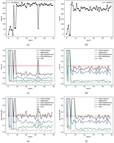
Figure 9.
Experiment results of Reward, CPU Occupancy, and Latency for Emergency and Satellite scenarios during the algorithm training: (a) Emergency Agent Reward; (b) Satellite Agent Reward; (c) Emergency Latency; (d) Satellite Latency; (e) Emergency CPU Occupancy; (f) Satellite CPU Occupancy.
To further illustrate the evolving process of the core network during training, we conducted a case study by plotting the core network structure from the perspective of its derived NFs and their constituent microservices in Figure 10. At each inference step, the trained agent decides to enrich the existing NF by adding a new microservice or generating a new NF. For the Emergency scenario, the agent decides to generate two NFs and connect them directly. The function of NF1 is equivalent to the traditional AUSF, while NF2 combines the functions of traditional AMF and SMF into one NF, which significantly reduces the signaling process latency and meets the primary requirements of the Emergency scenario. For the Satellite scenario, the agent constructs an evolved core network with three NFs. NF1 performs the same functions as traditional AUSF. The function of the traditional SMF is split by the agent into two parts, one is put into the NF2 as a Connection microservice and the other is put into the NF3 as a Session microservice, which integrates with the Registration microservice to form a new NF3. In other words, the NF3 combines part functions of the traditional SMF and AMF. This structure results in a reduction in CPU occupancy for task completion. From Figure 10, it can be seen that the agent has the ability to evolve the core network according to different scenarios by modifying the composition and topology of NFs.
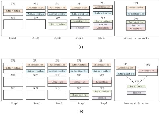
Figure 10.
The core network generation process of the trained agent for Emergency and Satellite scenarios. Each step refers the inference step of the algorithm. The microservices included by the NFs are plotted in different colors. The derived core network topology and NF constructions are plotted on the right side of the evolving process: (a) Evolving process of core network for Emergency scenario; (b) Evolving process of core network for Satellite scenario.
Finally, we compare the performance of the core networks generated by our self-evolution algorithm in the Emergency and Satellite scenarios to the General core network defined in Table 3 that was not subjected to evolution. As shown in Figure 11, in the Emergency scenario, the evolved network reduced the delays on the three tasks at the cost of increasing resource consumption. Specifically, the core network consolidated the session establishment and modification functions from SMF into AMF, resulting in lower delays for session establishment and modification. However, this led to an increase in resource consumption for AMF during registration. In the Satellite scenario, the evolved network reduced both CPU consumption and latency. The reason for this is that the evolving agent splits the SMF into two parts, separating session modification from session establishment, thereby reducing the CPU occupancy and delays for session modification.
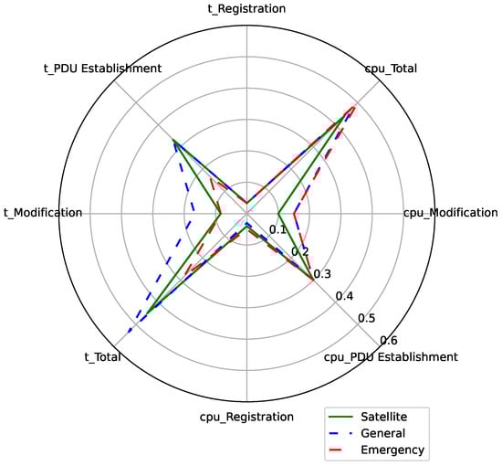
Figure 11.
Performance comparisons between the evolved core networks and the non-evolved one. Each dimension of the radar chart corresponds to the Latency t or CPU occupancy for one of the three tasks: Registration, PDU Session Establishment, and Session Modification. The total latency and CPU occupancy are also plotted.
7. Conclusions
In this paper, we propose a self-evolution architecture for the 6G core network, which is designed to accommodate diverse and constantly changing scenarios through intelligent decision making. Our contributions encompass elucidating the core ideas and mechanisms of 6G core network self-evolution, designing a pipeline, and introducing a reinforcement learning-based self-evolving agent along with a relevant algorithm. Through experimental simulations, we have validated the effectiveness of our self-evolution algorithm, demonstrating its ability to empower the agent with decision-making capabilities and ensure favorable environmental adaptability. For future work, we consider three points. First, we have discussed the evolving approaches for the Function, F, and Topology, T, of a ; however, we have not explicitly addressed the Protocol, P. When the network functions’ NFs are reconstructed, the corresponding core network protocols, which can be regarded as a conversation between NFs, would also be automatically regenerated. The AIGC (AI Generated Content) provides potential mechanisms for this aspect. Second, considering the physical or virtual environment of the Edge Core Network, the physical deployment of evolved network function instances should also be studied. Finally, the multi-agent evolution algorithm for the joint-optimization for the Cloud Core Networks and Edge Core Networks would also be studied.
Author Contributions
Conceptualization, L.L., C.L. and C.Z.; methodology, C.Z. and Z.L.; software, Z.L. and M.Z.; validation, Z.L., M.Z., X.L. and J.C.; formal analysis, S.L.; investigation, Z.L. and M.Z.; writing—original draft preparation, Z.L., M.Z., X.L. and J.C.; writing—review and editing, C.Z., Z.L., M.Z., X.L. and J.C.; visualization, Z.L. and M.Z.; supervision, L.L., C.L., C.Z. and Z.H.; project administration, L.L., C.L. and Z.H. All authors have read and agreed to the published version of the manuscript.
Funding
This research was funded by BUPT-CMCC Joint Innovation Center grant number 1.
Data Availability Statement
The data presented in this study are available on request from the corresponding author. The data are not publicly available due to privacy concerns regarding the data simulation platform.
Acknowledgments
This work was supported by the Beijing University of Posts and Telecommunication-China Mobile Research Institution Joint Innovation Center.
Conflicts of Interest
The authors declare no conflict of interest. The funder involved in the decision to publish the results.
References
- Lu, Y.; Zheng, X. 6G: A survey on technologies, scenarios, challenges, and the related issues. J. Ind. Inf. Integr. 2020, 19, 100158. [Google Scholar] [CrossRef]
- Wang, C.X.; You, X.; Gao, X.; Zhu, X.; Li, Z.; Zhang, C.; Wang, H.; Huang, Y.; Chen, Y.; Haas, H.; et al. On the Road to 6G: Visions, Requirements, Key Technologies, and Testbeds. IEEE Commun. Surv. Tutor. 2023, 25, 905–974. [Google Scholar] [CrossRef]
- Yang, H.; Alphones, A.; Xiong, Z.; Niyato, D.; Zhao, J.; Wu, K. Artificial-Intelligence-Enabled Intelligent 6G Networks. IEEE Netw. 2020, 34, 272–280. [Google Scholar] [CrossRef]
- Yang, Y.; Ma, M.; Wu, H.; Yu, Q.; Zhang, P.; You, X.; Wu, J.; Peng, C.; Yum, T.S.P.; Shen, S.; et al. 6G network AI architecture for everyone-centric customized services. arXiv 2022, arXiv:2205.09944. [Google Scholar] [CrossRef]
- Zhang, S. An Overview of Network Slicing for 5G. IEEE Wirel. Commun. 2019, 26, 111–117. [Google Scholar] [CrossRef]
- Choi, Y.j.; Lee, K.B.; Bahk, S. All-IP 4G Network architecture for efficient mobility and resource management. IEEE Wirel. Commun. 2007, 14, 42–46. [Google Scholar] [CrossRef]
- Song, L.; Xu, Z.; Tian, Z.; Chen, J.; Zhi, R. Research on 4G And 5G Authentication Signaling. J. Phys. Conf. Ser. 2019, 1213, 042048. [Google Scholar] [CrossRef]
- Lauridsen, M.; Gimenez, L.C.; Rodriguez, I.; Sorensen, T.B.; Mogensen, P. From LTE to 5G for Connected Mobility. IEEE Commun. Mag. 2017, 55, 156–162. [Google Scholar] [CrossRef]
- Ezhilarasan, E.; Dinakaran, M. A Review on Mobile Technologies: 3G, 4G and 5G. In Proceedings of the 2017 Second International Conference on Recent Trends and Challenges in Computational Models (ICRTCCM), Tindivanam, India, 3–4 February 2017; pp. 369–373. [Google Scholar] [CrossRef]
- Akhtar, M.W.; Hassan, S.A.; Ghaffar, R.; Jung, H.; Garg, S.; Hossain, M.S. The shift to 6G communications: Vision and requirements. Hum.-Centric Comput. Inf. Sci. Vol. 2020, 10, 53. [Google Scholar] [CrossRef]
- Gupta, A.; Savarese, S.; Ganguli, S.; Fei-Fei, L. Embodied intelligence via learning and evolution. Nat. Commun. 2021, 12, 5721. [Google Scholar] [CrossRef]
- Wang, T.; Zhou, Y.; Fidler, S.; Ba, J. Neural graph evolution: Towards efficient automatic robot design. arXiv 2019, arXiv:1906.05370. [Google Scholar]
- Yuan, Y.; Song, Y.; Luo, Z.; Sun, W.; Kitani, K. Transform2act: Learning a transform-and-control policy for efficient agent design. arXiv 2021, arXiv:2110.03659. [Google Scholar]
- Brown, G. Service-based architecture for 5g core networks. Huawei White Paper 2017, 1. Available online: https://www.3g4g.co.uk/5G/5Gtech_6004_2017_11_Service-Based-Architecture-for-5G-Core-Networks_HR_Huawei.pdf (accessed on 18 May 2023).
- Saha, T.; Aaraj, N.; Jha, N.K. Machine Learning Assisted Security Analysis of 5G-Network-Connected Systems. IEEE Trans. Emerg. Top. Comput. 2022, 10, 2006–2024. [Google Scholar] [CrossRef]
- Lv, Z.; Chen, D.; Lou, R.; Wang, Q. Intelligent edge computing based on machine learning for smart city. Future Gener. Comput. Syst. 2021, 115, 90–99. [Google Scholar] [CrossRef]
- Jeunen, O.; Bosch, P.; Herwegen, M.V.; Doorselaer, K.V.; Godman, N.; Latré, S. A Machine Learning Approach for IEEE 802.11 Channel Allocation. In Proceedings of the 2018 14th International Conference on Network and Service Management (CNSM), Rome, Italy, 5–9 November 2018; pp. 28–36. [Google Scholar]
- Li, R.; Zhao, Z.; Zhou, X.; Ding, G.; Chen, Y.; Wang, Z.; Zhang, H. Intelligent 5G: When Cellular Networks Meet Artificial Intelligence. IEEE Wirel. Commun. 2017, 24, 175–183. [Google Scholar] [CrossRef]
- Kukushkin, A. Third Generation Network (3G), UMTS. In Introduction to Mobile Network Engineering: GSM, 3G-WCDMA, LTE and the Road to 5G; Wiley Telecom: Piscataway, NJ, USA, 2018; pp. 121–172. [Google Scholar] [CrossRef]
- Hicham, M.; Abghour, N.; Ouzzif, M. 4G System: Network Architecture and Performance. Int. J. Innov. Res. Adv. Eng. (IJIRAE) 2015, 2, 215–220. [Google Scholar]
- Akyildiz, I.F.; Wang, P.; Lin, S.C. SoftAir: A software defined networking architecture for 5G wireless systems. Comput. Netw. 2015, 85, 1–18. [Google Scholar] [CrossRef]
- You, X.; Wang, C.X.; Huang, J.; Gao, X.; Zhang, Z.; Wang, M.; Huang, Y.; Zhang, C.; Jiang, Y.; Wang, J.; et al. Towards 6G wireless communication networks: Vision, enabling technologies, and new paradigm shifts. Sci. China Inf. Sci. 2021, 64, 110301. [Google Scholar] [CrossRef]
- Bhat, J.R.; Alqahtani, S.A. 6G Ecosystem: Current Status and Future Perspective. IEEE Access 2021, 9, 43134–43167. [Google Scholar] [CrossRef]
- Tataria, H.; Shafi, M.; Molisch, A.F.; Dohler, M.; Sjöland, H.; Tufvesson, F. 6G Wireless Systems: Vision, Requirements, Challenges, Insights, and Opportunities. arXiv 2021, arXiv:2008.03213. [Google Scholar] [CrossRef]
- Hu, Z.; Zhang, P.; Zhang, C.; Zhuang, B.; Zhang, J.; Lin, S.; Sun, T. Intelligent decision making framework for 6G network. China Commun. 2022, 19, 16–35. [Google Scholar] [CrossRef]
- Duan, X.; Sun, T.; Liu, C.; Ma, X.; Hu, Z.; Lu, L.; Zhang, C.; Zhuang, B.; Li, W.; Wang, S. Cognitive intelligence based 6G distributed network architecture. China Commun. 2022, 19, 137–153. [Google Scholar] [CrossRef]
- Corici, M.; Troudt, E.; Chakraborty, P.; Magedanz, T. An Ultra-Flexible Software Architecture Concept for 6G Core Networks. In Proceedings of the 2021 IEEE 4th 5G World Forum (5GWF), Montreal, QC, Canada, 13–15 October 2021; pp. 400–405. [Google Scholar] [CrossRef]
- Yu, Q.; Ren, J.; Zhou, H.; Zhang, W. A Cybertwin based Network Architecture for 6G. In Proceedings of the 2020 2nd 6G Wireless Summit (6G SUMMIT), Levi, Finland, 17–20 March 2020; pp. 1–5. [Google Scholar] [CrossRef]
- Li, Y.; Huang, J.; Sun, Q.; Sun, T.; Wang, S. Cognitive Service Architecture for 6G Core Network. IEEE Trans. Ind. Inform. 2021, 17, 7193–7203. [Google Scholar] [CrossRef]
- Fang, X.; Feng, W.; Wei, T.; Chen, Y.; Ge, N.; Wang, C.X. 5G embraces satellites for 6G ubiquitous IoT: Basic models for integrated satellite terrestrial networks. IEEE Internet Things J. 2021, 8, 14399–14417. [Google Scholar] [CrossRef]
- Wang, C.; Zhang, P.; Kumar, N.; Liu, L.; Yang, T. GCWCN: 6G-based Global Coverage Wireless Communication Network Architecture. IEEE Netw. 2022, 1–7. [Google Scholar] [CrossRef]
- Corici, M.; Troudt, E.; Magedanz, T.; Schotten, H. Organic 6G Networks: Decomplexification of Software-based Core Networks. In Proceedings of the 2022 Joint European Conference on Networks and Communications & 6G Summit (EuCNC/6G Summit), Grenoble, France, 7–10 June 2022; pp. 541–546. [Google Scholar] [CrossRef]
- Zhang, P.; Peng, M.; Cui, S.; Zhang, Z.; Mao, G.; Quan, Z.; Quek, T.Q.S.; Rong, B. Theory and techniques for “intellicise” wireless networks. Front. Inf. Technol. Electron. Eng. 2022, 23, 1–4. [Google Scholar] [CrossRef]
- Maier, M.; Ebrahimzadeh, A.; Rostami, S.; Beniiche, A. The Internet of No Things: Making the Internet Disappear and “See the Invisible”. IEEE Commun. Mag. 2020, 58, 76–82. [Google Scholar] [CrossRef]
- Cai, L.; Pan, J.; Yang, W.; Ren, X.; Shen, X. Self-Evolving and Transformative (SET) Protocol Architecture for 6G. IEEE Wirel. Commun. 2022, 1–12. [Google Scholar] [CrossRef]
- Liu, C.; Lu, L.; Wang, S.; Hu, Y.S. Prospects for a Multi-Access Air-Space-Terrestrial Integrated 6G Network Architecture. Mob. Commun. 2020, 44, 116–120. [Google Scholar]
- Letaief, K.B.; Chen, W.; Shi, Y.; Zhang, J.; Zhang, Y.J.A. The roadmap to 6G: AI empowered wireless networks. IEEE Commun. Mag. 2019, 57, 84–90. [Google Scholar] [CrossRef]
- Zhang, S.; Zhu, D. Towards artificial intelligence enabled 6G: State of the art, challenges, and opportunities. Comput. Netw. 2020, 183, 107556. [Google Scholar] [CrossRef]
- Khattak, S.B.A.; Nasralla, M.M.; Rehman, I.U. The Role of 6G Networks in Enabling Future Smart Health Services and Applications. In Proceedings of the 2022 IEEE International Smart Cities Conference (ISC2), Pafos, Cyprus, 26–29 September 2022; IEEE: Piscataway, NJ, USA, 2022; pp. 1–7. [Google Scholar]
- Hao, Y.; Miao, Y.; Chen, M.; Gharavi, H.; Leung, V.C.M. 6G Cognitive Information Theory: A Mailbox Perspective. Big Data Cogn. Comput. 2021, 5, 56. [Google Scholar] [CrossRef]
- Papidas, A.G.; Polyzos, G.C. Self-organizing networks for 5g and beyond: A view from the top. Future Internet 2022, 14, 95. [Google Scholar] [CrossRef]
- Chen, W.; Montojo, J.; Lee, J.; Shafi, M.; Kim, Y. The standardization of 5G-Advanced in 3GPP. IEEE Commun. Mag. 2022, 60, 98–104. [Google Scholar] [CrossRef]
- Rahman, I.; Razavi, S.M.; Liberg, O.; Hoymann, C.; Wiemann, H.; Tidestav, C.; Schliwa-Bertling, P.; Persson, P.; Gerstenberger, D. 5G evolution toward 5G Advanced: An overview of 3GPP releases 17 and 18. Ericsson Technol. Rev. 2021, 2021, 2–12. [Google Scholar] [CrossRef]
- Nasralla, M.M.; Khattak, S.B.A.; Ur Rehman, I.; Iqbal, M. Exploring the Role of 6G Technology in Enhancing Quality of Experience for m-Health Multimedia Applications: A Comprehensive Survey. Sensors 2023, 23, 5882. [Google Scholar] [CrossRef]
- Azari, M.M.; Solanki, S.; Chatzinotas, S.; Kodheli, O.; Sallouha, H.; Colpaert, A.; Montoya, J.F.M.; Pollin, S.; Haqiqatnejad, A.; Mostaani, A.; et al. Evolution of non-terrestrial networks from 5G to 6G: A survey. IEEE Commun. Surv. Tutor. 2022, 24, 2633–2672. [Google Scholar] [CrossRef]
- Shen, X.; Gao, J.; Wu, W.; Li, M.; Zhou, C.; Zhuang, W. Holistic Network Virtualization and Pervasive Network Intelligence for 6G. IEEE Commun. Surv. Tutor. 2022, 24, 1–30. [Google Scholar] [CrossRef]
- Sutton, R.S.; Barto, A.G. Reinforcement Learning: An Introduction; MIT Press: Cambridge, CA, USA, 2018. [Google Scholar]
- Schulman, J.; Wolski, F.; Dhariwal, P.; Radford, A.; Klimov, O. Proximal policy optimization algorithms. arXiv 2017, arXiv:1707.06347. [Google Scholar]
- Li, Z.; Shang, C.; Wu, J.; Li, Y. Microservice extraction based on knowledge graph from monolithic applications. Inf. Softw. Technol. 2022, 150, 106992. [Google Scholar] [CrossRef]
- Raj, V.; Ravichandra, S. A service graph based extraction of microservices from monolith services of service-oriented architecture. Softw. Pract. Exp. 2022, 52, 1661–1678. [Google Scholar] [CrossRef]
- go-callvis. Available online: https://github.com/ofabry/go-callvis (accessed on 18 May 2023).
- Free5GC. Available online: https://www.free5gc.org/ (accessed on 18 May 2023).
- Blondel, V.D.; Guillaume, J.L.; Lambiotte, R.; Lefebvre, E. Fast Unfolding of Communities in Large Networks. J. Stat. Mech. Theory Exp. 2008, 2008, P10008. [Google Scholar] [CrossRef]
- Fritzsch, J. From Monolithic Applications to Microservices Guidance on Refactoring Techniques and Result Evaluation. Master’s Thesis, Reutlingen University, Reutlingen, Germany, 2018. [Google Scholar]
- Rafiq, A.; Muthanna, M.S.A.; Muthanna, A.; Alkanhel, R.; Abdullah, W.A.M.; Abd El-Latif, A.A. Intelligent edge computing enabled reliable emergency data transmission and energy efficient offloading in 6tisch-based iiot networks. Sustain. Energy Technol. Assess. 2022, 53, 102492. [Google Scholar] [CrossRef]
- Ghiglione, M.; Serra, V. Opportunities and challenges of ai on satellite processing units. In Proceedings of the 19th ACM International Conference on Computing Frontiers, Turin, Italy, 17–22 May 2022; pp. 221–224. [Google Scholar]
- Brockman, G.; Cheung, V.; Pettersson, L.; Schneider, J.; Schulman, J.; Tang, J.; Zaremba, W. Openai gym. arXiv 2016, arXiv:1606.01540. [Google Scholar]


Disclaimer/Publisher’s Note: The statements, opinions and data contained in all publications are solely those of the individual author(s) and contributor(s) and not of MDPI and/or the editor(s). MDPI and/or the editor(s) disclaim responsibility for any injury to people or property resulting from any ideas, methods, instructions or products referred to in the content. |
© 2023 by the authors. Licensee MDPI, Basel, Switzerland. This article is an open access article distributed under the terms and conditions of the Creative Commons Attribution (CC BY) license (https://creativecommons.org/licenses/by/4.0/).