Abstract
Based on the problems of sliding mode observer (SMO), such as strong parameter dependency, large overshoot, and severe inherent sliding mode chattering, this paper studies fuzzy control in depth using a sigmoid (s) function with smooth and continuous characteristics instead of a discontinuous symbolic function to design a new type of fuzzy sliding mode observer. Firstly, the boundary layer thickness was introduced to enable the system to achieve adaptive sliding mode gain adjustment based on the system state. Then, based on PLL technology, PI adjustment was used to obtain rotor position information. Finally, in order to verify the effectiveness of the new method, a model was built for experimental verification, and the simulation waveforms of the traditional sliding mode observer and the new fuzzy sliding mode observer were compared. The results show that the new fuzzy sliding mode observer can more accurately estimate rotor position and speed information. Under the same operating conditions, the rotational speed estimation error is only 3 r/min, the rotor position error is reduced by 0.1 rad, the overshoot is smaller, and the chattering is significantly reduced.
1. Introduction
With the increase in global energy demand, air pollutants become serious and harm the Earth, so the resolution for decreasing pollutants and fuel diversification is imperative. With the development of technology and the transformation of energy, the powertrain based on electricity is popular and mainstream; thus, the downstream application scenarios of rare earth permanent magnet synchronous motors (PMSMs) continue to open up, such as automobiles, wind energy, variable frequency air conditioners, consumer electronics, and so on. The demands of new energy vehicles, industrial energy-saving motors, and industrial robots are also booming. In the future, potential demand growth points for humanoid robots, permanent magnetic levitation track technology, and other technologies may continue to emerge. Driven by emerging and traditional demands, rare earth PMSM has become a research hotspot in the theoretical field. At present, there are three main control methods for permanent magnet synchronous motors: square wave control [1,2], sine wave control [3,4], and field-oriented control (FOC) [5,6]. Square wave control is a six-step commutation control based on the position of the rotor, with large torque fluctuations and low efficiency. The sine wave control method uses an SVPWM wave, which outputs a three-phase sine wave voltage, and the corresponding current is also a sine wave current. The sine wave control achieves voltage vector control, indirectly controlling the magnitude of the current, but cannot control the direction of the current. FOC is a technology that uses a frequency converter (VFD) to control three-phase motors. It controls the output of the motor by adjusting the output frequency, voltage, and angle of the inverter. The FOC control method not only achieves current vector control, but also achieves vector control of the stator magnetic field of the motor, making the motor torque stable, with low noise, high power, and high-speed dynamic response. It is the best choice for achieving effective control of permanent magnet synchronous motors (PMSMs). FOC control is divided into sensor-based FOC and sensorless FOC [7,8]. For FOC based on sensors, the encoder feedbacks the position information of the motor rotor, so the control strategy is relatively simple, but the research mainly focuses on the improvement of power performance. The sensorless FOC, due to its simple wiring, low cost, high reliability, and the ability to maximize control objectives such as high efficiency, low vibration, low noise, and high response speed, is a mainstream developing trend and research hotspot.
Currently, the control methods based on sensorless FOC mainly include model reference adaptive control [9,10], the high-frequency injection method [11,12], the extended Kalman filtering method [13,14], the sliding mode observer method [15,16], and so on. Among them, sliding mode observer (SMO) has the advantages of strong control robustness, no need for system identification, and good dynamic response characteristics, and is widely used. Many scholars carried out substantial research on this topic. Dai, L. et al. and Zhang, Q. et al. [17,18,19] proposed a sliding mode observer based on the super spiral algorithm for sensorless control of permanent magnet synchronous motors, which uses fixed sliding mode coefficients to suppress system chattering, but cannot achieve accurate estimation of rotational speed and rotor position, has a poor ability to suppress system interference, and is not robust. Huang, K. et al. and Gu, C. et al. [20,21], according to the characteristics that position estimation errors can lead to an imbalance in the current state equation, implemented closed-loop adjustment outside the SMO to achieve adaptive compensation for estimation errors. However, these methods often directly add the estimated position angle and compensation angle without considering the corresponding estimated speed. Therefore, when the delay is large, it is not possible to ensure that the motor speed loop output is still stable. Sreejith, R. et al. [22] proposed a sliding mode observer based on a dual second-order generalized integrator phase-locked loop. By combining an integrator phase-locked loop with a feedforward term, the new method effectively eliminates the harmonics of the estimated back electromotive force component and avoids the use of a low-pass filter (LPF). However, this algorithm is difficult to implement and the positioning accuracy is moderate.
The methods mentioned above improve the control effectiveness compared to traditional sliding mode observers, but the system algorithm is complex and costly, and current observation errors have a significant impact on rotor position accuracy. Therefore, a new fuzzy adaptive sliding mode observer based on boundary layer adaptation is proposed in this research, which uses continuous functions instead of discontinuous symbolic functions, introduces boundary layer parameters, and establishes fuzzy rules. The current observation error and its derivative are input variables, and the boundary layer thickness is the output. Then, based on phase-locked loop (PLL), the rotor position information is obtained from the back electromotive force. The advantages of this design are as follows:
- (1)
- Strong robustness. When the internal parameters change or are subject to external interference, the impact of the current error on the back electromotive force (EMF) is reduced, and the anti-interference ability is improved.
- (2)
- High precision. The introduction of boundary layer thickness allows the control system to adjust the sliding mode gain in real time based on the magnitude of current observation errors, achieving adaptive adjustment of the sliding mode gain and improving the rotor position accuracy.
- (3)
- Widely applicable. The fuzzy adaptive controller designed in this article is suitable for permanent magnet synchronous motors of different powers in various fields, which can significantly reduce the overshoot and static error of various performance indicators of the motor and effectively reduce system chattering. It can be applied to various control scenarios, such as motor control and robotic arm control.
- (4)
- Simple and practical. The fuzzy sliding mode control is a commonly used nonlinear control method. It does not need an accurate system model, but only needs to design a fuzzy sliding mode controller according to the actual control requirements to achieve stable control of the system.
2. Mathematical Model of PMSM
The sliding mode observer is designed in the synchronous rotating coordinate system. Let and be the induced electromotive force in the d–q axis coordinate system, then the stator voltage equation of the three-phase PMSM is as follows:
where , , and are the stator voltage of the d–q axis, is the stator resistance, and are the current of the d–q axis, and are the inductance of the d–q axis, and are the stator flux of the d–q axis, is the motor angular velocity, and is the permanent magnet flux.
According to Equation (1), the stator current equation of PMSM can be expressed as follows:
Then, by real-time detection of stator voltage and stator current, according to the counter-electromotive force method, the rotor position and other information during the current motor operation can be estimated, and the sensorless control of the motor can be realized through feedback.
3. Design of Traditional SMO
In order to obtain the values of and , the sliding mode observer can be designed according to Formula (2) as follows:
where and are the current observations of the d–q axis, and is the sliding mode gain factor. Subtract Equations (3) and (4) to obtain the state equation of the current error system as follows:
Among them, and are current observation errors. The state equation is rewritten into vector form and expressed as follows:
In Formula (6), , , , , and .
Since the sliding mode observer is designed to estimate the current instead of the real motor model, the sliding mode surface function is defined as follows:
When the sliding mode gain factor k is large enough, . According to the Lyapunov stability existence theorem, the sliding mode observer meets the design requirements and can enter the sliding mode in a limited time.
When the system enters sliding mode, there is
Substitute Formula (6) into Formula (8) to obtain
The hyperbolic tangent function belongs to the switching function, and will contain discontinuous high-frequency signals generated by the system switching, which will be filtered by the filter to obtain the equivalent control quantity, namely,
where is the observed value of the electrical angle. According to the Lyapunov theorem, to maintain the stability of SMO, it is necessary to fully meet the condition , an expression that can calculate , as follows:
Among them, n is a positive number. When n is not less than 2, the sliding mode reaches a steady state.
4. Fuzzy Sliding Mode Observer Based on New Sigmoid (s) Function
The observed value of affects the dynamic response performance and buffeting of the system, and its accuracy directly affects the accuracy of the rotor position and speed in sensorless control. In order to calculate the value of more accurately, the fuzzy control algorithm is introduced into the sliding mode observer, and a new fuzzy sliding mode observer is designed. First, the sigmoid (s) function with smooth characteristics is used in the SMO algorithm to avoid frequency agility, and then the boundary layer parameter reconstruct function is introduced to achieve observation scale changes; after reconstruction, it can be expressed as
where a is a positive number, and its size affects the convergence of the function. The fuzzy control model is composed of two inputs and one output. Taking current observation error and its derivative as input, as system output, then
Based on the fuzzy sigmoid (s) function, the equivalent control quantity can be expressed as follows:
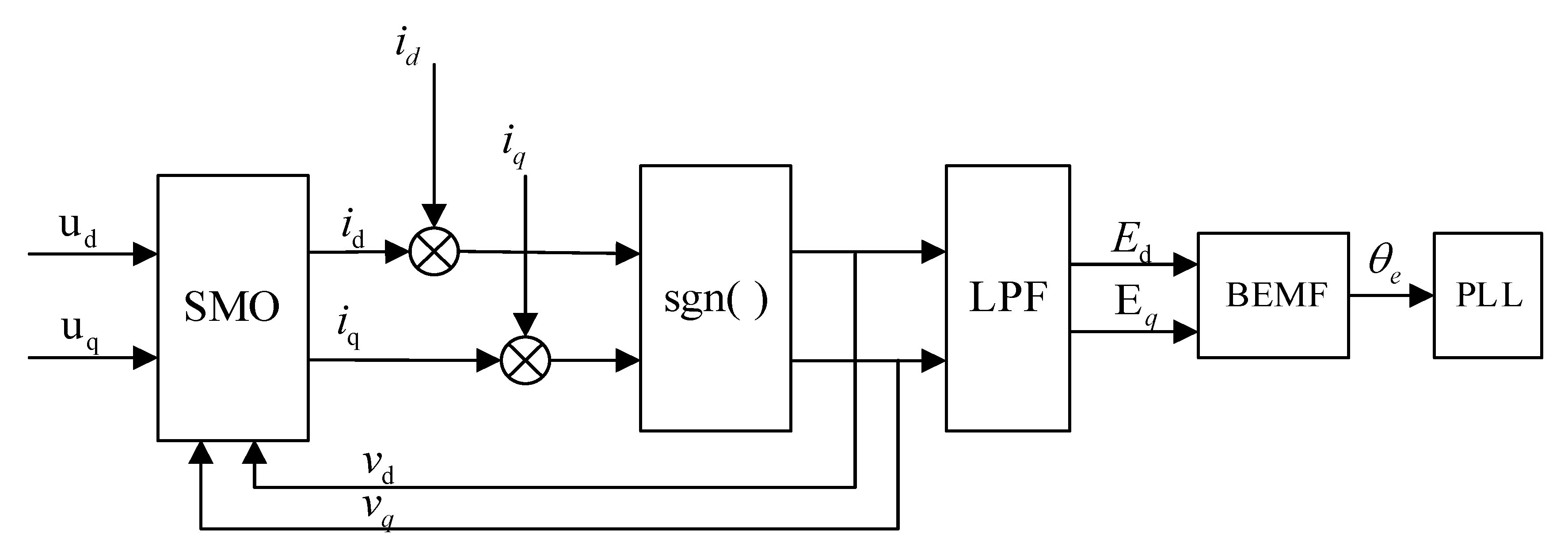
The schematic diagrams of traditional SMO and new fuzzy SMO control are shown in Figure 1 and Figure 2.

Figure 1.
Schematic diagram of traditional SMO control.
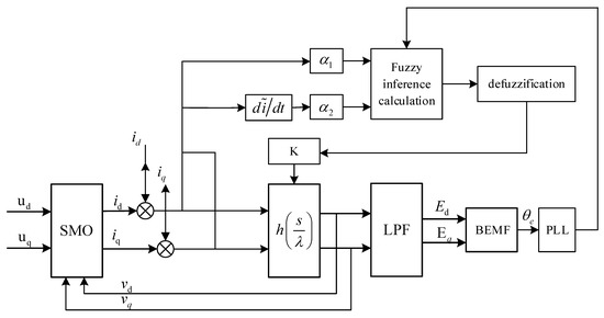
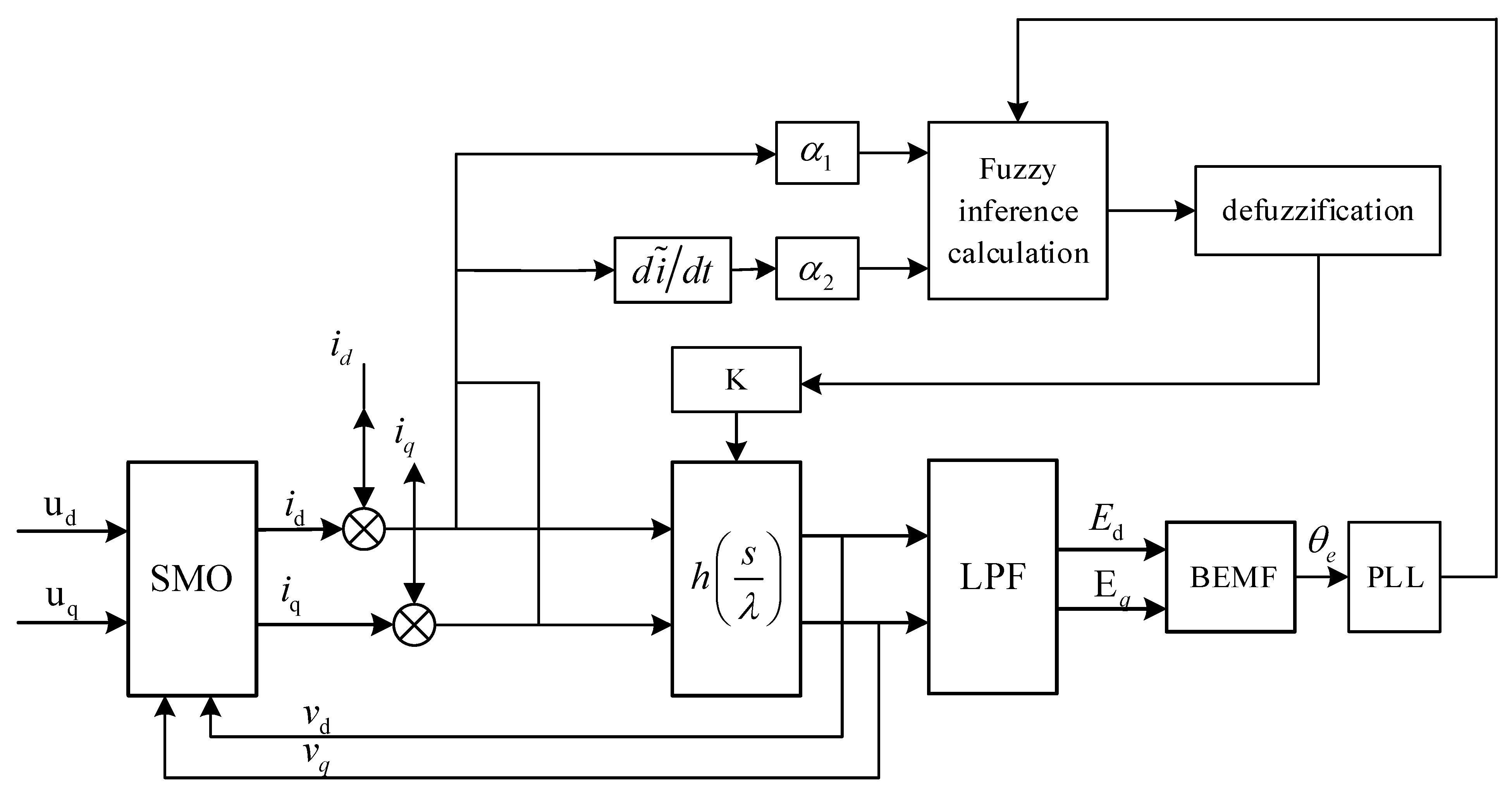
Figure 2.
Schematic diagram of a new type of fuzzy SMO control.
The traditional sliding mode observer uses a Sign function with a fixed gain value to estimate the counter-electromotive force. A small gain cannot achieve a good control effect, and a large gain can easily cause chattering. Moreover, the derivative of the Sign function is discontinuous, and the gain also needs to be adjusted adaptively according to the system situation. The new fuzzy controller starts from the characteristics of the sigmoid () function, introduces the thickness of the boundary layer, and designs a new sigmoid () function. According to the current error and the relationship between the derivative and coefficient of the current error, a fuzzy algorithm is introduced to determine the fuzzy rules of the three phases, and a new sliding mode observer with quasi-sliding mode characteristics is designed. The thickness of the boundary layer of the new sliding mode observer can be adjusted adaptively.
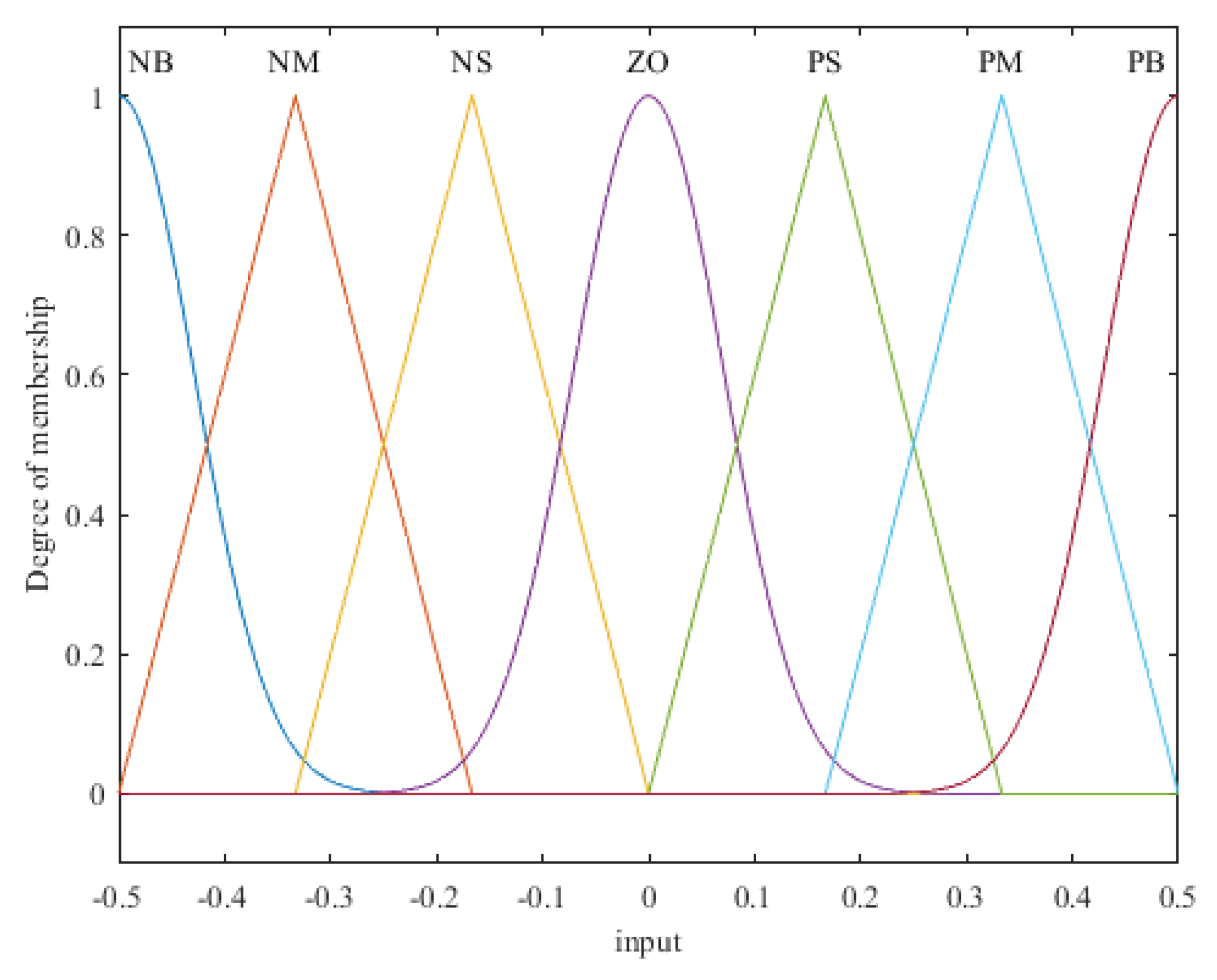
In the fuzzy controller, input and and output each contain seven fuzzy subsets, defined as negative large (NB), negative medium (NM), negative small (NS), zero (ZO), positive small (PS), median (PM), and large board (PB). The corresponding rules of input and output are shown in Table 1, and the discussion domains are , , and .

Table 1.
Fuzzy control rules.
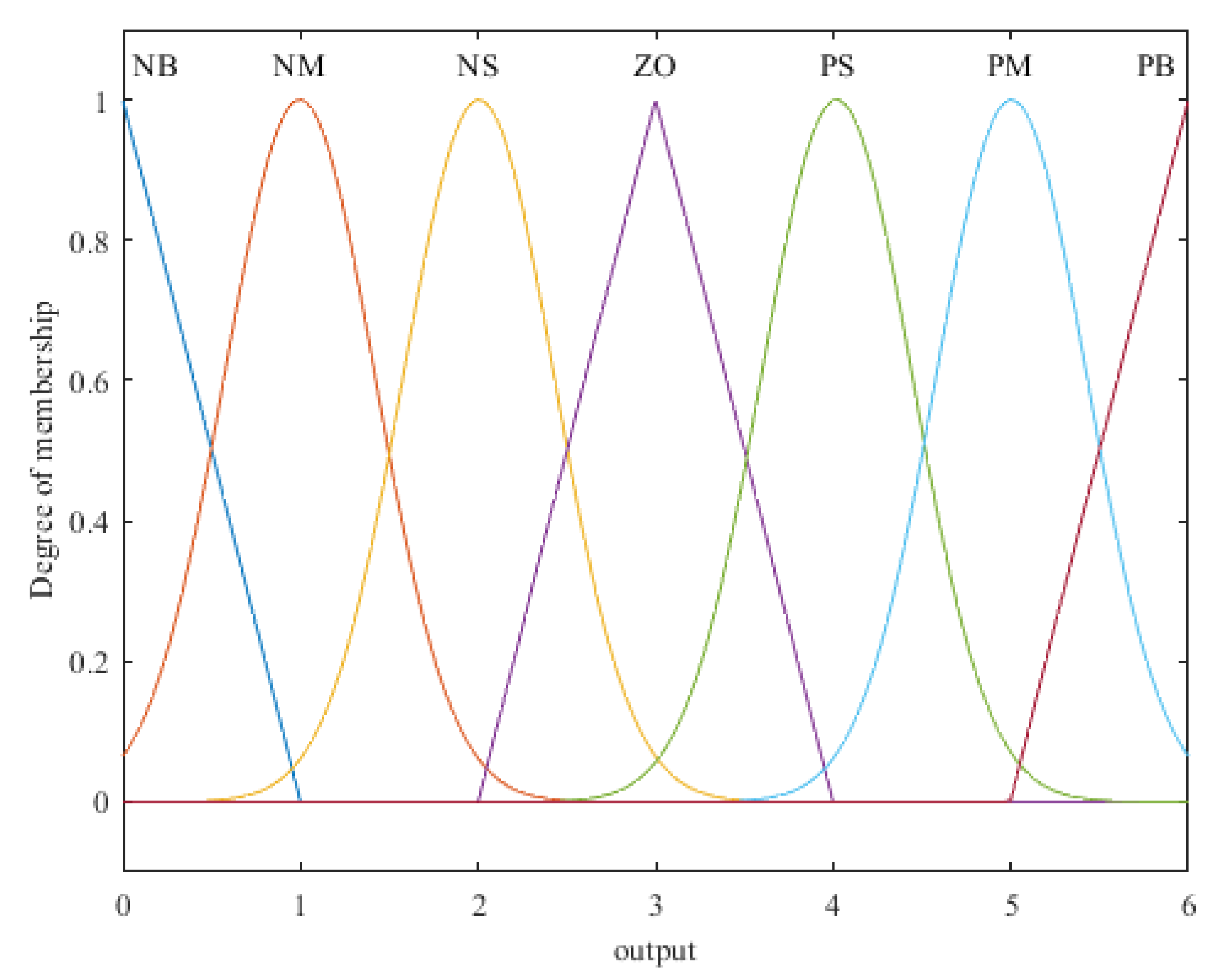
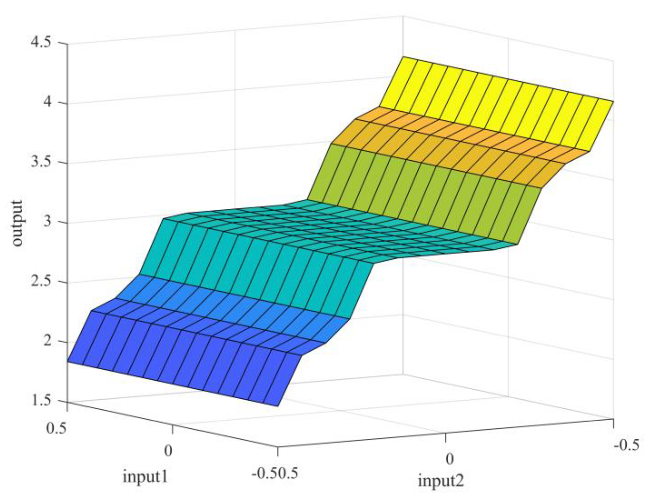
The input and output of fuzzy control adopt the composite function of Gaussian membership function and trigonometric functions, and the membership graphs of input and are the same, as shown in Figure 3. The output membership graph is shown in Figure 4. Mamdani fuzzy logic reasoning and center of gravity de-fuzzification are adopted for fuzzy control. The sliding mode surface model after fuzzy control is shown in Figure 5.
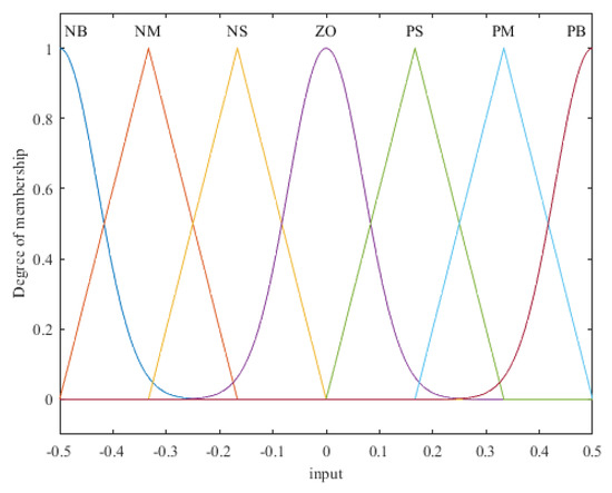
Figure 3.
Input membership function.
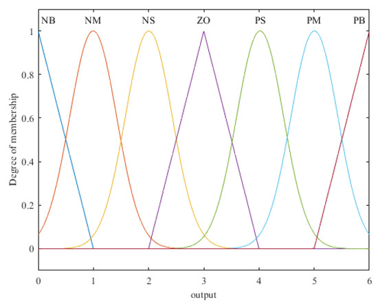
Figure 4.
Output membership function.

Figure 5.
Fuzzy back sliding surface model.
The established fuzzy control model is applied to the new sliding mode controller. When the current error is large, the system state variable is far away from the sliding mode surface, and the fuzzy control rules will output a small gain, which makes the variable move close to the sliding mode surface. When the current error is small, the fuzzy control rule will output a large gain to reduce chattering. This design allows for real-time changes in sliding mode gain with current observation errors, ensuring that the E value can enter the sliding mode surface more quickly, improve the dynamic response speed of the system, effectively weaken the chattering of the system, reduce the rotor speed fluctuation, and make the rotor position and speed information more accurate.
5. Rotor Position Estimation Based on a New Fuzzy Sliding Mode Observer
Through the new fuzzy sliding mode observer designed above, the induced electromotive force of axis q is obtained, and , which contains the rotor speed information. According to Equation (10), the rotor speed estimation is obtained:
In the process of motor operation, the flux of the permanent magnet is not a constant value, so the rotor position information and motor speed are not consistent with the actual value, which will cause errors and affect the control performance of the PMSM system. In order to achieve better control performance, PLL technology is used to estimate rotor position information and speed, which has excellent tracking performance. Since the winding of the three-phase motor is symmetrical, the terminal voltage of the stator winding is assumed:
where u is the voltage amplitude of the machine terminal. Note , , where is the pole number of the motor and n is the mechanical speed. Then, the three-phase voltage is converted to the d–q axis:
where , and is the estimated phase angle of output.
The estimated error obtained by the PLL technique is , and . When , , that is, the estimated rotor position converges to the actual value. Substitute Equation (17) into Equation (16):
The closed-loop control block diagram of the PI regulator can be obtained from Equation (18), as shown in Figure 6.
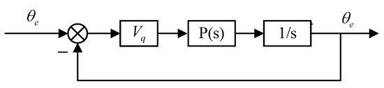
Figure 6.
PI regulation closed-loop block diagram.
As shown in Figure 4, the closed-loop function of the system is
where s is a Laplace variable. The transfer function of the PI regulator is
Equations (18) and (19) are combined as follows:
According to the expected bandwidth of the closed-loop system, the parameters of the PI regulator can be written as follows:
Finally, rotor position information can be obtained according to PI adjustment.
6. Test Verification
In order to verify the effectiveness of the new fuzzy sliding mode observer in the synchronous rotating coordinate system, the model was built in the MATLAB/Simulink simulation environment according to the system control block diagram shown in Figure 7, the red part shows the new fuzzy controller designed. The control mode adopts the vector control method with , and the motor parameters are shown in Table 2.
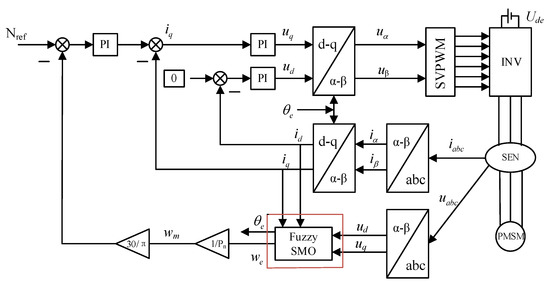
Figure 7.
Control block diagram of permanent magnet synchronous motor.
Table 2.
Parameters of permanent magnet synchronous motor.
After the model was built, the initial test conditions were as follows: DC side voltage = 311 V, switching frequency of PWM = 10 kHz, a = 0.2, n = 3, , where is calculated based on Formula (11). We built a simulation model of a discrete system, selected the fixed step size ode3 (Bogacki–Shampine) algorithm, and set the fixed step time to 10−5 s. The cutoff frequency of the low-pass filter was 3000 rad·s−1. The PI regulator of the PLL system was set to Kp = 30, Ki = 450. The parameters were kept unchanged, and the waveforms of the traditional sliding mode observer and the new fuzzy sliding mode observer were compared under two conditions of speed mutation and load mutation.
6.1. Speed Mutation Condition
We set the model runs without load; the simulation time was 1 s, and the initial speed was 800 r·min−1. The speed mutation was 1200 r·min−1 after 0.35 s, then 1500 r·min−1 after 0.7 s. The results are shown in Figure 8, Figure 9, Figure 10, Figure 11 and Figure 12.
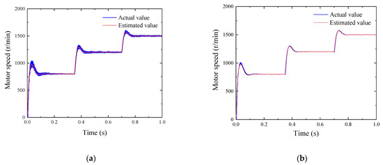
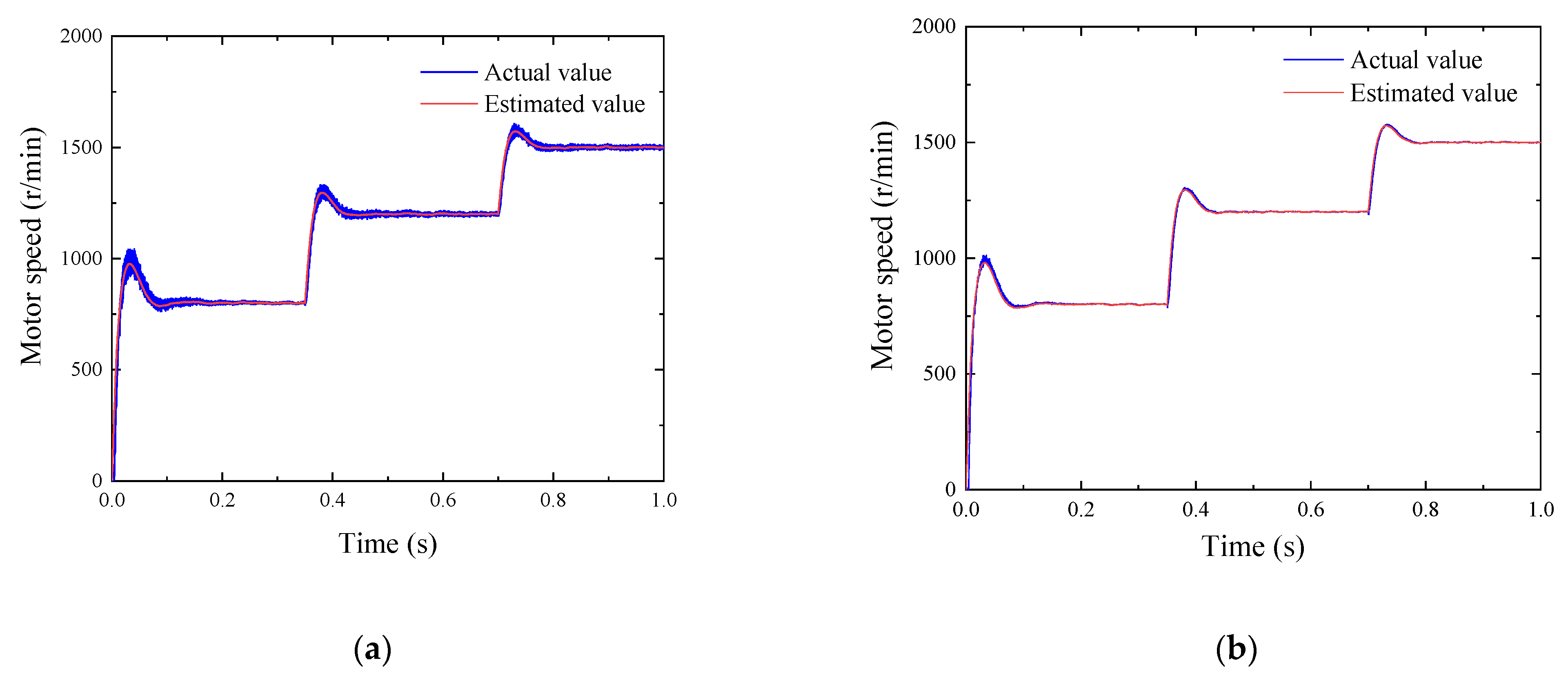
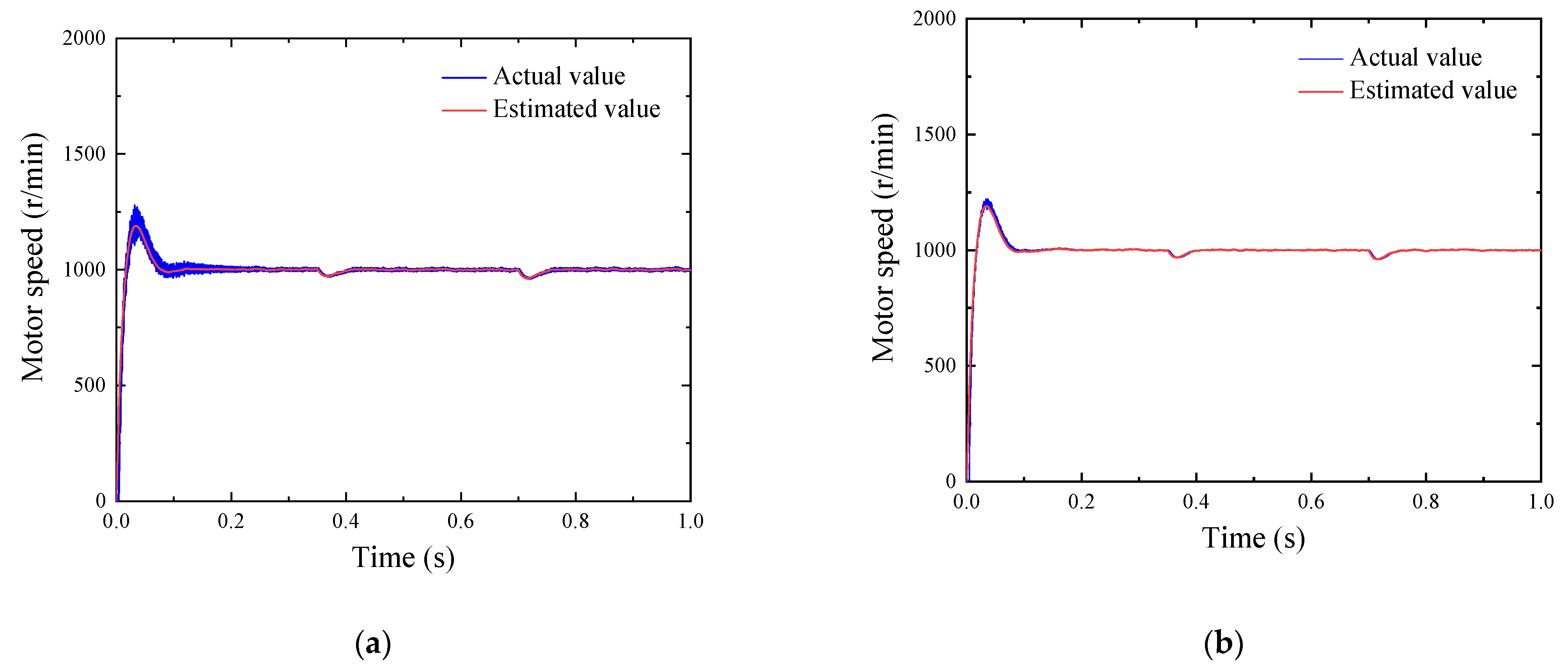
Figure 8.
Comparison of speed change under sudden changes in speed. (a) Variation curve of traditional estimated and actual SMO speed. (b) The change curve of the new fuzzy SMO speed estimate and the actual value.
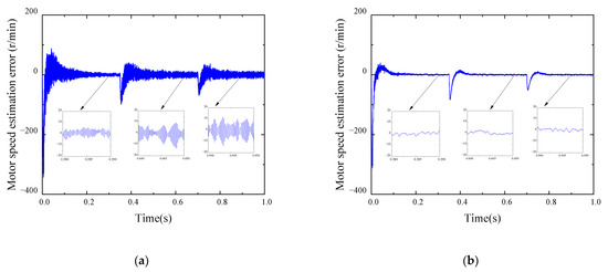
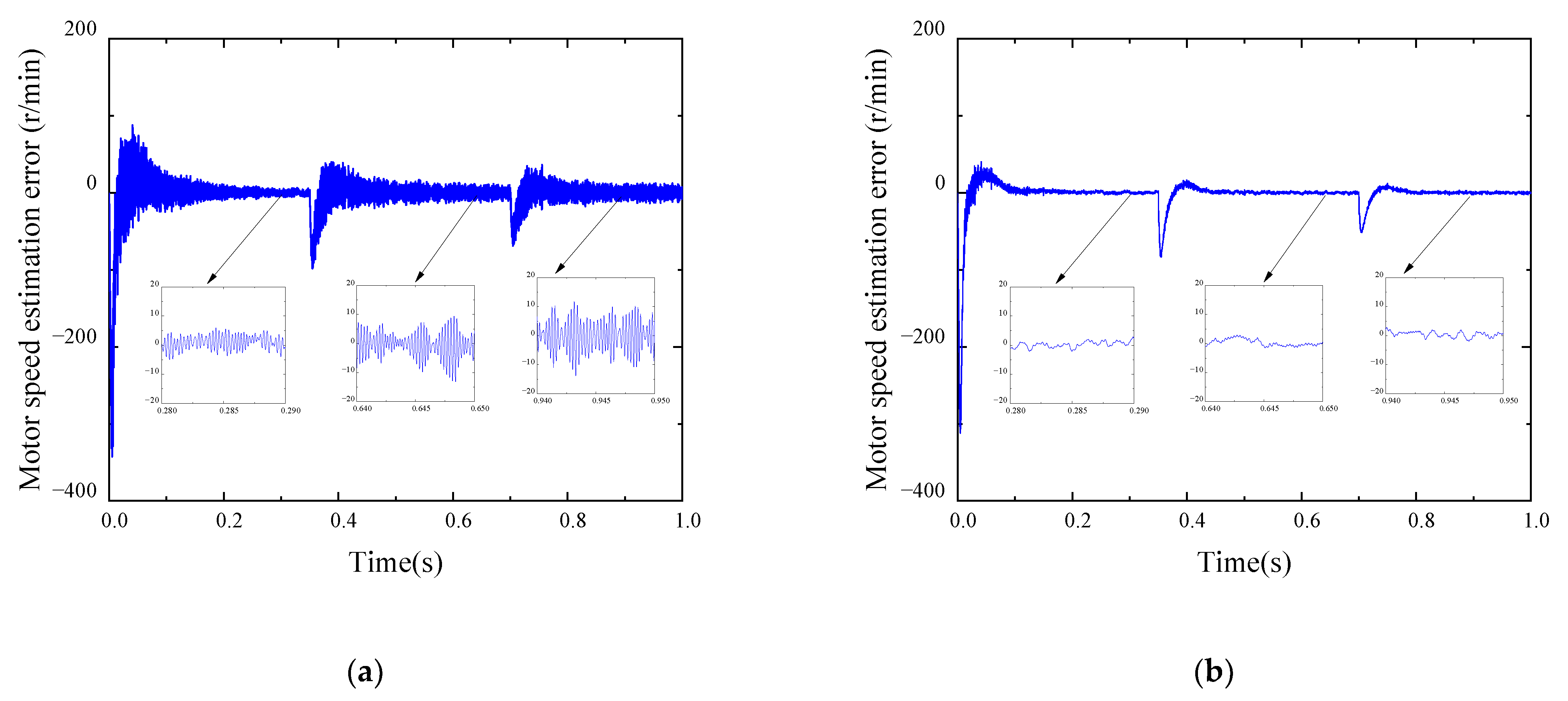
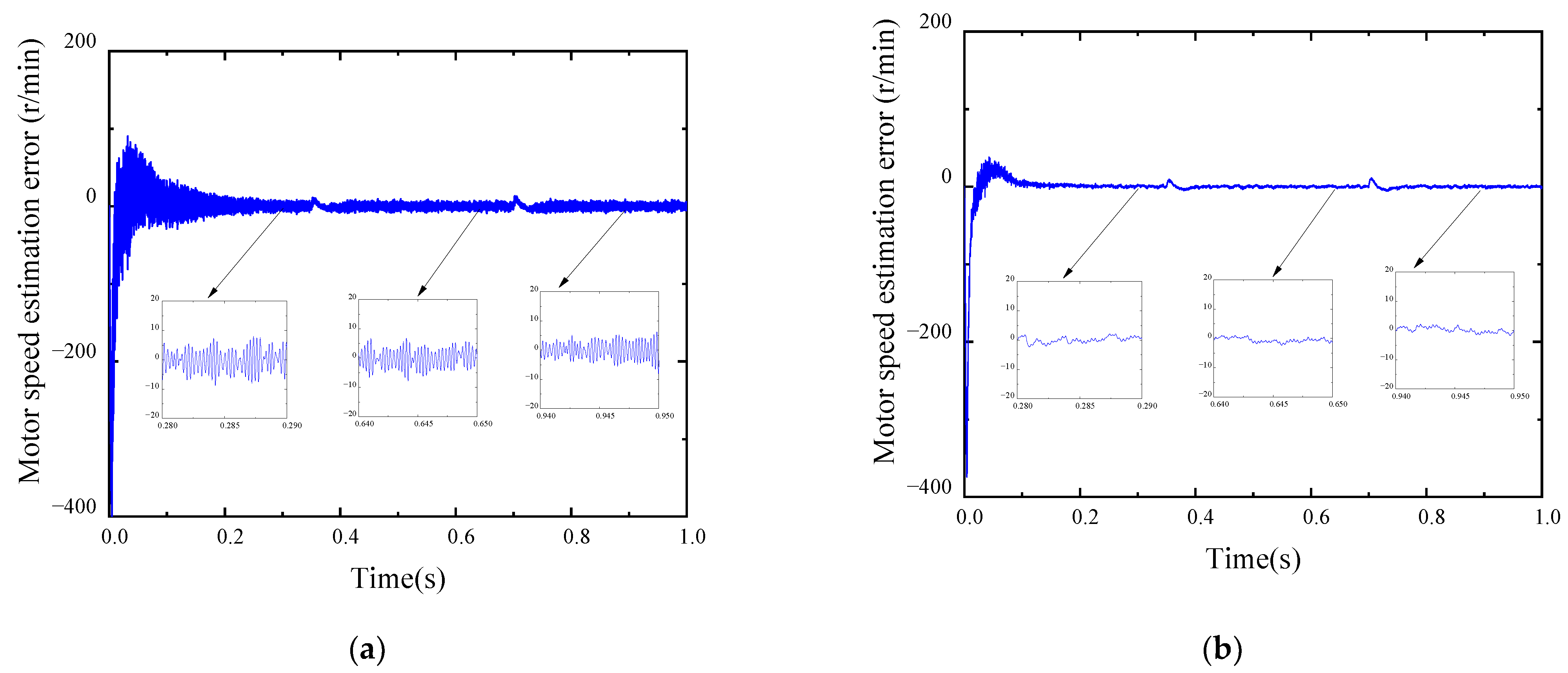
Figure 9.
Comparison of speed error under sudden changes in speed. (a) Traditional SMO speed estimation error curve. (b) Variation curve of speed estimation error of a new fuzzy SMO.
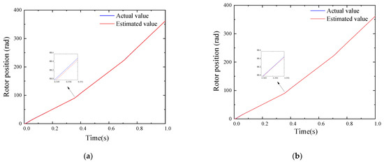
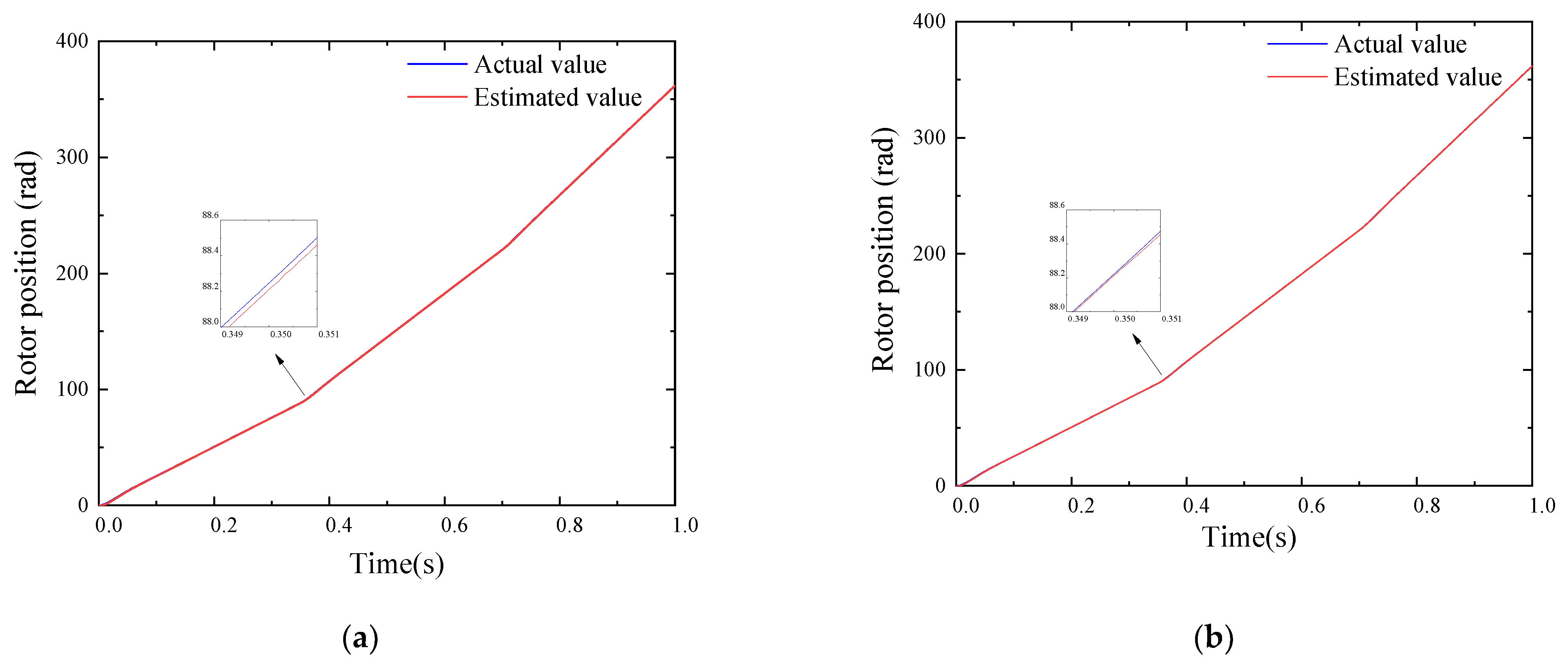
Figure 10.
Comparison of rotor position under sudden speed changes. (a) Traditional SMO rotor position actual value and estimated value curve. (b) New fuzzy SMO rotor position actual value and estimated value curve.
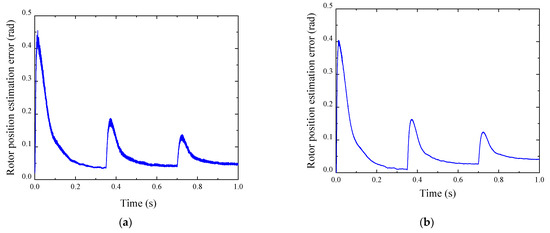
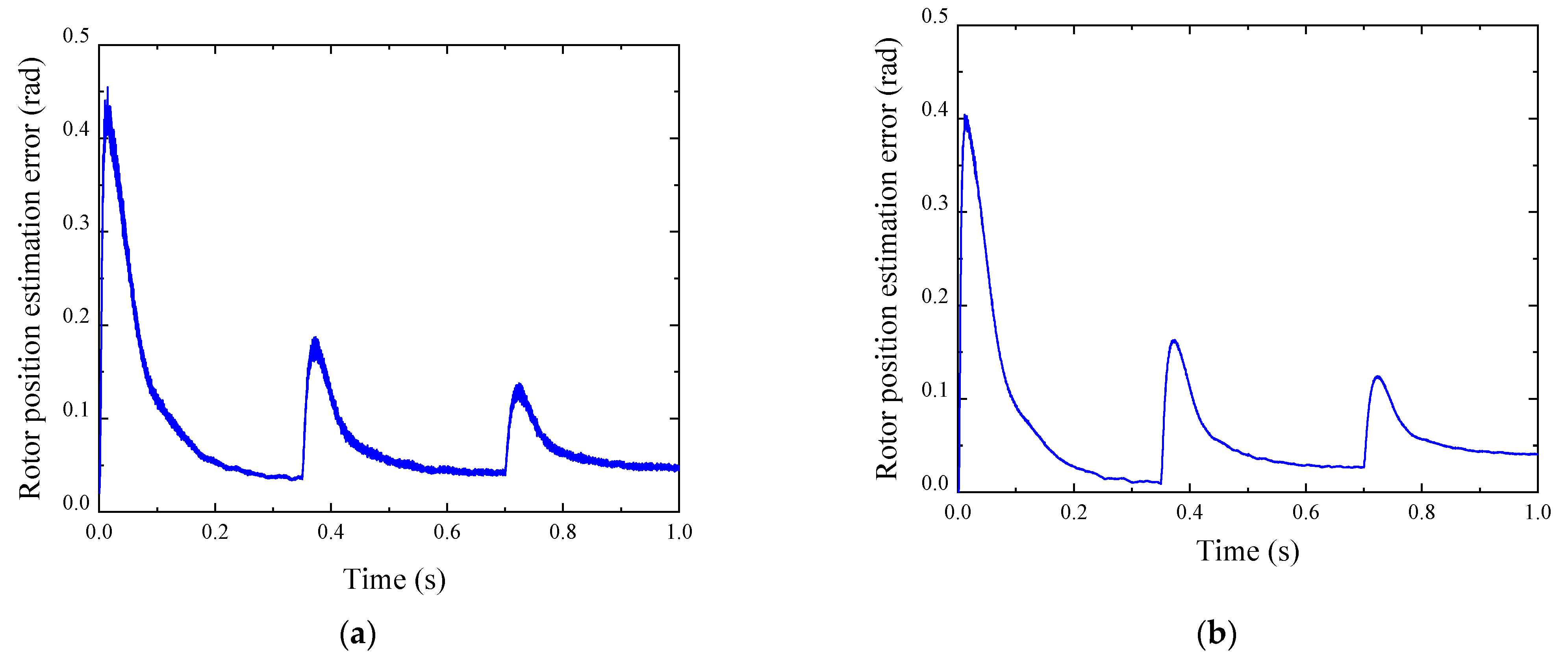
Figure 11.
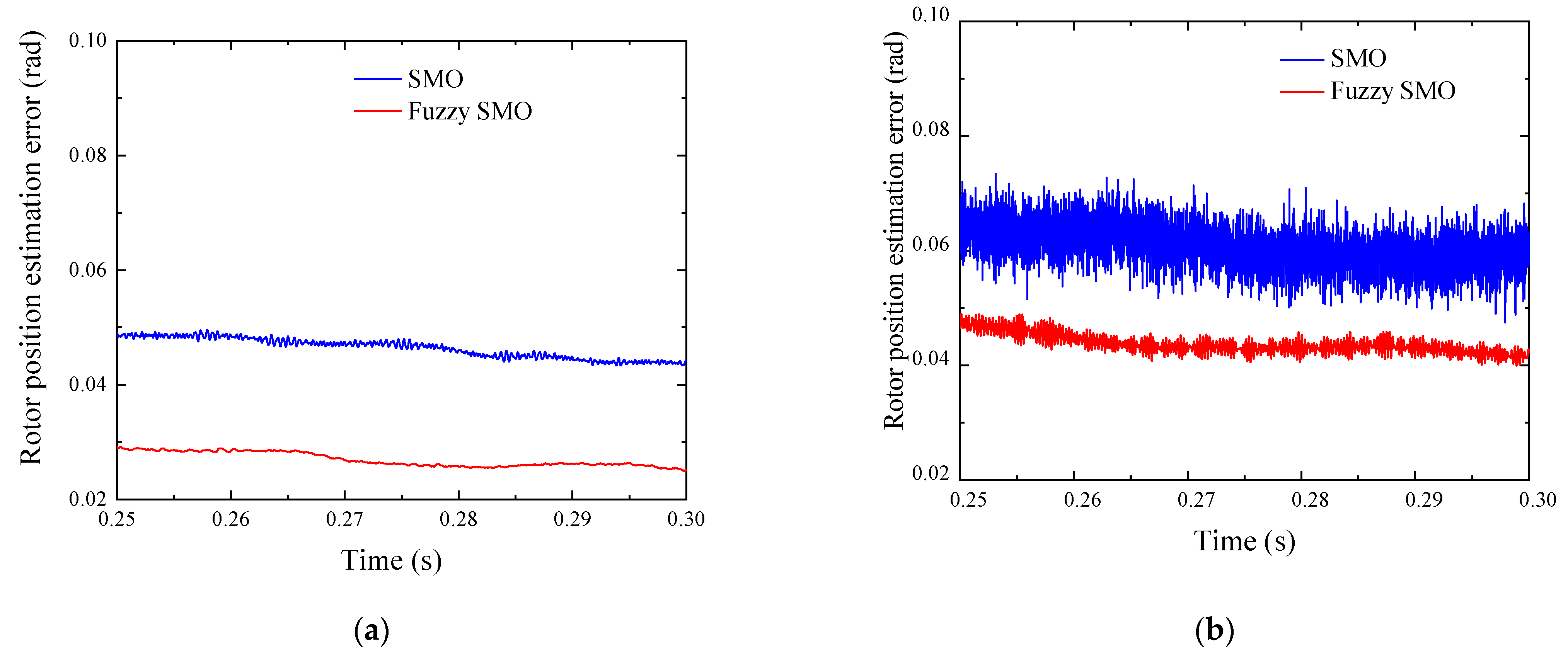
Comparison of rotor position error under sudden speed changes. (a) Traditional SMO rotor position estimation error curve. (b) New fuzzy SMO rotor position estimation error curve.
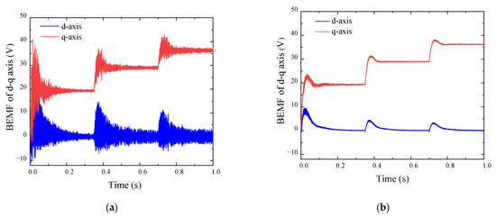
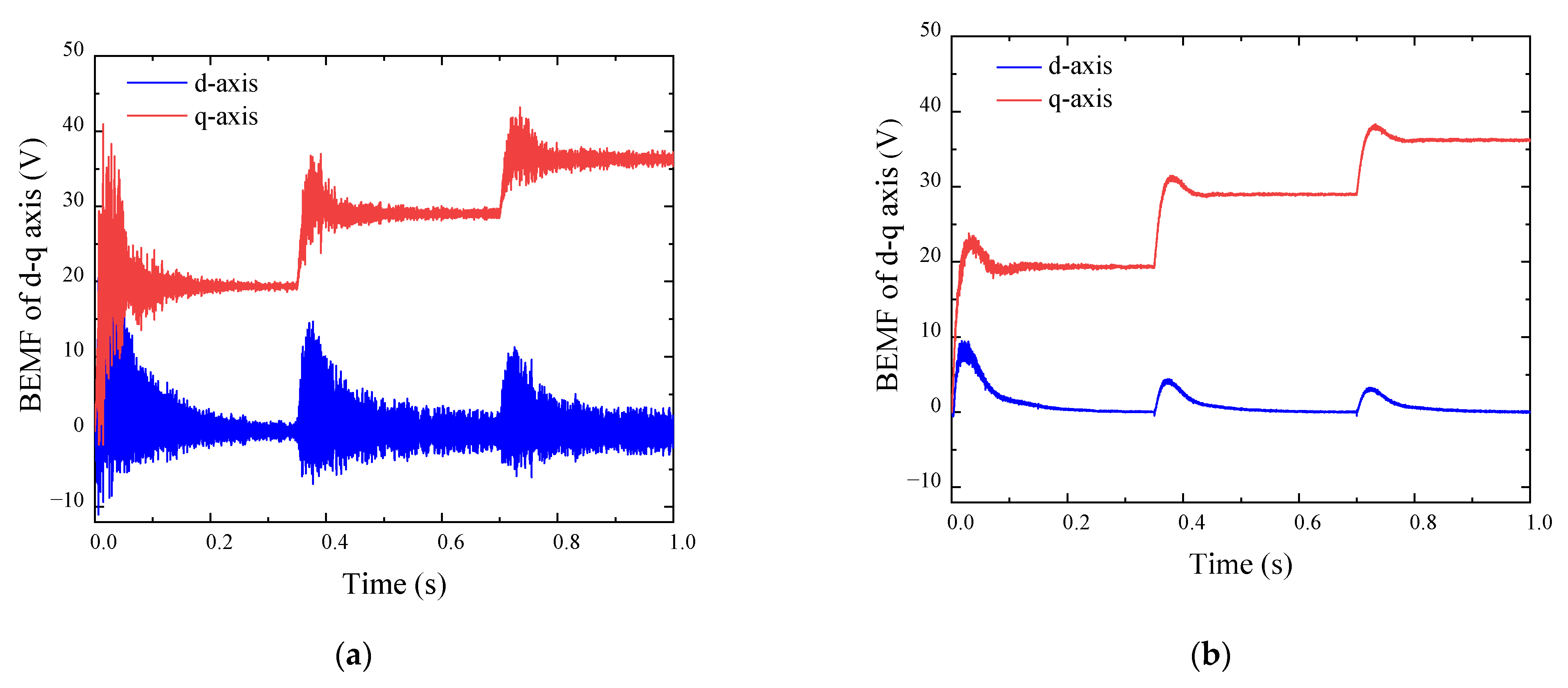
Figure 12.
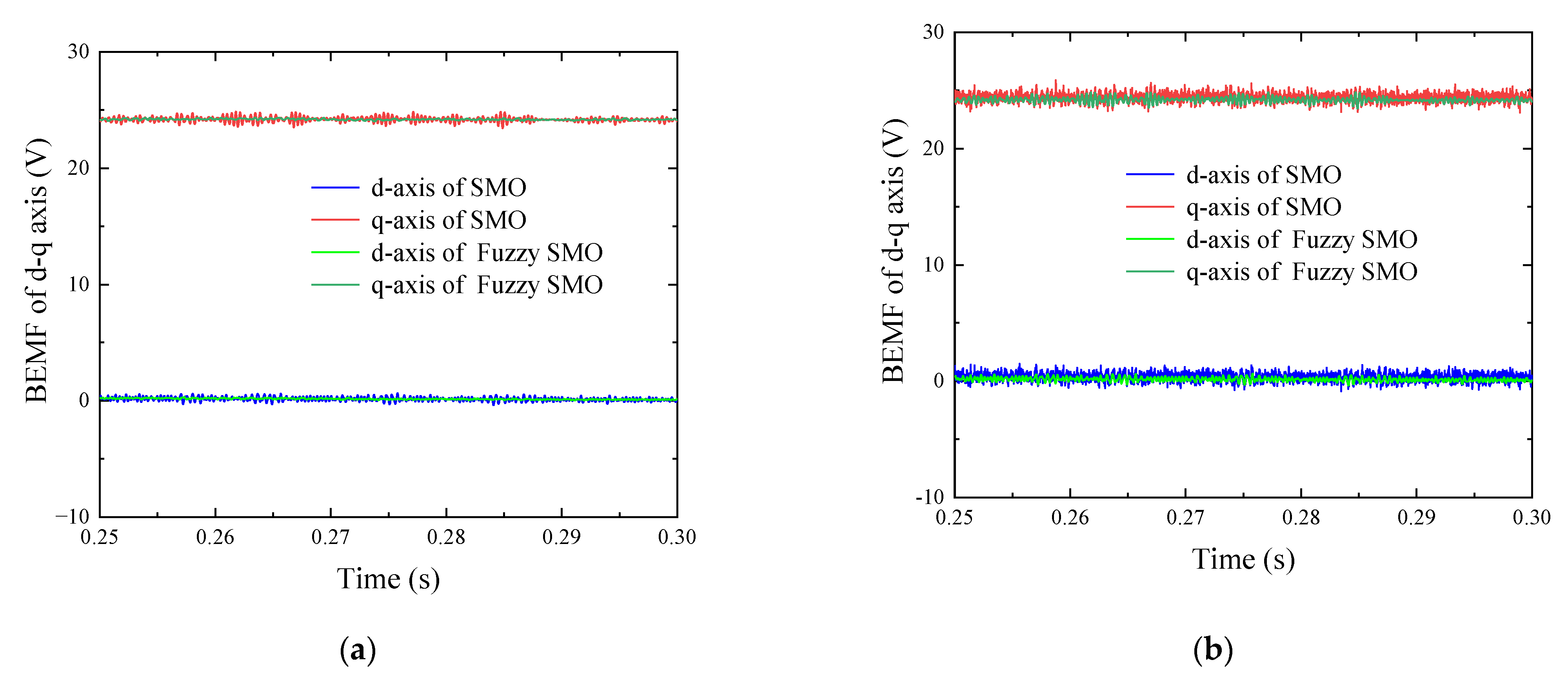
Comparison of BEMF under sudden speed changes. (a) Conventional SMO d–q axis induced electromotive force. (b) Improved induced electromotive force of SMO d–q axis.
A comparison of the motor speed and the speed estimation error between the traditional SMO and the improved new fuzzy SMO under load step conditions was carried out, as shown in Figure 8 and Figure 9. As can be seen, during the speed step process, the motor speed estimation error of the traditional SMO increases as the speed increases, from 8 r·min−1 to 15 r·min−1, but the speed estimation error of the new fuzzy SMO is only 3 r·min−1 at 800 r/min, 1200 r·min−1, and 1500 r·min−1, remaining basically unchanged. The static error of the new fuzzy SMO is smaller; its estimated speed value is closer to the actual value. In addition, combining the speed curve and the speed estimation error curve, it can be seen that the estimated value of the new fuzzy SMO basically coincides with the actual value after the first and second sudden changes in rotational speed and only has a very small overshoot, which enters a stable state about 0.1 s after mutation; however, the traditional SMO requires 0.15 s, and the response speed is improved by about 33%. The experimental results show that the new fuzzy SMO has strong anti-interference ability, less chattering, faster response speed, and better tracking performance, verifying the effectiveness of the new fuzzy SMO.
A comparison of the actual values, estimated values, and estimated errors of the motor rotor position under speed step conditions between a traditional SMO and the improved new fuzzy SMO was carried out, as shown in Figure 10 and Figure 11. As can be seen, the estimation error curve of the new fuzzy sliding mode observer is smoother than the estimation error curve of the traditional fuzzy sliding mode observer in the above figures, and after taking partial time to amplify for the waveform in Figure 10a,b, the distance between the estimated value curve in Figure 10b and the actual value curve is smaller, indicating that the estimation error is smaller. In addition, after the system is stable, the static error of the new fuzzy SMO is also small. This is because the fuzzy SMO designed in this paper changes the magnitude of the sliding mode gain in real time based on the current observation error, which improves the rotor position accuracy. The experimental results show that compared with traditional SMO, the new fuzzy SMO has smaller chattering, more accurate estimation of rotor position information, and smaller error, which verifies the effectiveness of the new fuzzy SMO.
BEMF is an important parameter in motor control strategies. Position sensorless PMSM usually uses observation of BEMF to obtain rotor position information. To measure the effectiveness of sensorless control, it is necessary to analyze BEMF. A comparison of the d–q axis induced electromotive force of a motor with a traditional SMO and the improved new fuzzy SMO was carried out, as shown in Figure 12. As can be seen, the d–q axis BEMFs fluctuate around 0 after stabilization, indicating that the model is correct. At the speed of 800 r/min, the d–q axis induced electromotive force of the new fuzzy SMO tends to stabilize at about 0.2 s, with less chattering, but the traditional SMO tends to stabilize at about 0.3 s. After a sudden change in speed, the new fuzzy SMO also enters a stable state about 0.1 s in advance, and the new fuzzy SMO responds faster. In addition, the overshoot of the new fuzzy SMO after each speed change is significantly smaller, but the fluctuation amplitude of the d–q axis induced electromotive force in traditional SMO increases with the increase in speed. The comparison shows that the control effect of the new fuzzy SMO is better, which verifies the effectiveness of the new fuzzy SMO.
6.2. Sudden Load Condition
We set the motor speed to 1000 r·min−1, the simulation time to 1 s, and the initial load to 0.5 N·m. The load mutation was 0.8 N·m after 0.35 s, and then a sudden change of 1.2 N·m after 0.7 s. The results are shown in Figure 13, Figure 14, Figure 15, Figure 16 and Figure 17.
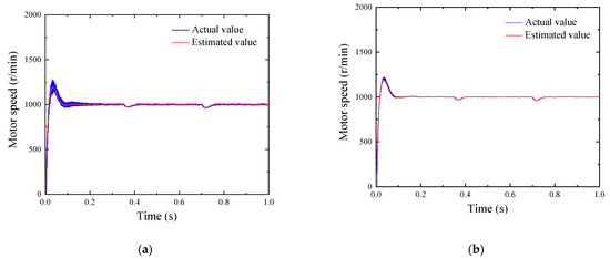
Figure 13.
Comparison of speed under sudden load changes. (a) Variation curve of traditional estimated and actual SMO speed. (b) The change curve of the new fuzzy SMO speed estimate and the actual value.

Figure 14.
Comparison of speed error under sudden load changes. (a) Traditional SMO speed estimation error curve. (b) Variation curve of speed estimation error of a new fuzzy SMO.
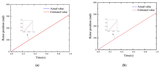
Figure 15.
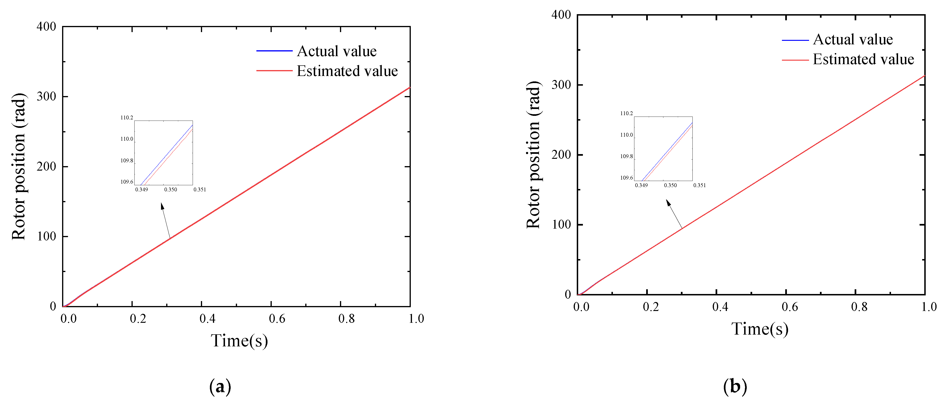
Comparison of rotor positions under sudden load changes. (a) Traditional SMO rotor position actual value and estimated value curve. (b) New fuzzy SMO rotor position actual value and estimated value curve.
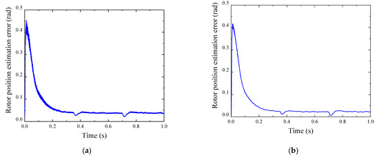
Figure 16.
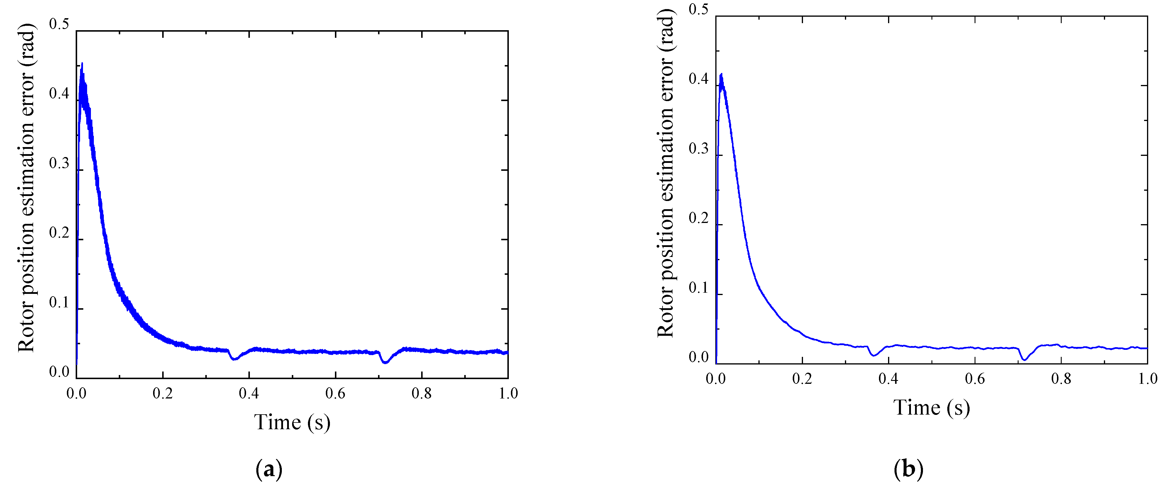
Comparison of rotor position errors under sudden load changes. (a) Traditional SMO rotor position estimation error curve. (b) New fuzzy SMO rotor position estimation error curve.
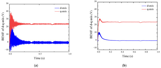
Figure 17.
Comparison of BEMF under sudden load changes. (a) Conventional SMO d–q axis induced electromotive force. (b) Improved induced electromotive force of SMO d–q axis.
Figure 11, Figure 12, Figure 13, Figure 14 and Figure 15 show the performance index comparison curve between the traditional SMO and the improved new fuzzy SMO under load step conditions. As can be seen, the load suddenly changed from 0.5 N · m to 0.8 N · m, and then suddenly changed to 1.2 N · m. The rotational speed error of the new fuzzy SMO is only 3 r/min in these three cases, which remains basically unchanged, and it is 15 r/min lower than that of the traditional SMO. When the load suddenly changes to 1.2 N · m and enters a stable state, the rotor position error decreases from about 0.4 rad to about 0.28 rad, a decrease of 30%. After a sudden change in load, the speed error and rotor position error remain basically unchanged, and the overshoot decreases significantly, allowing for faster entry into a stable state, indicating that the new fuzzy SMO has higher control accuracy and faster response speed. In addition, from the perspective of graph shape, the variation curve of traditional SMO is rougher and burrier, while the curve controlled by new fuzzy SMO is finer and smoother, indicating that its static error and system flutter are smaller.
7. Experiment Validation
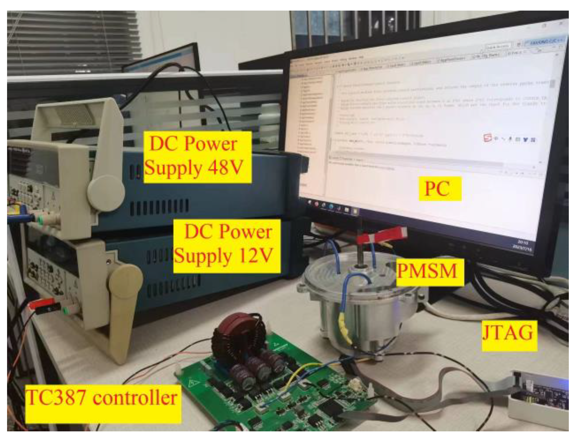
On the basis of theoretical and simulation verification, a test platform was built, as shown in Figure 18. The control chip used the TC387 chip produced by Infineon and a three-phase inverter circuit designed based on the IMBG120R045M1H silicon carbide MOSFET transistor. There were two power supplies, one providing a 48 V power supply converted into 311 V through a boost circuit to supply power to the inverter circuit, and the other outputting a 12 V power supply to the microcontroller and signal conditioning circuit through a Buck circuit. The experimental parameters of PMSM are the same as those in Table 2.

Figure 18.
Experimental setup.
The initial speed was set at 1000 r · min−1, the load was 0.8 N · m, and the experimental time was 0.4 s. Experimental verification was conducted on traditional SMO and new fuzzy SMO. After the motor ran stably, the experimental results were compared with the simulation conditions. The experimental results at the beginning are shown in Figure 19 and Figure 20. In practical environments, due to power and controller limitations, as well as internal factors of the motor, there may be problems such as startup delay or insufficient acceleration. Therefore, in the actual environment, open-loop control technology was used for startup, and the experimental results are shown in Figure 19, Figure 20 and Figure 21.
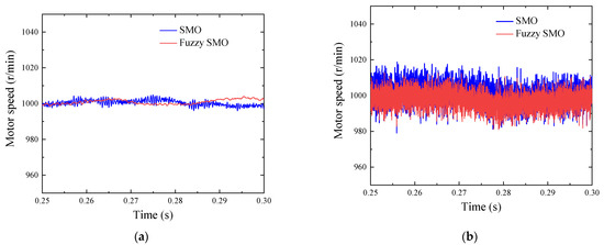
Figure 19.
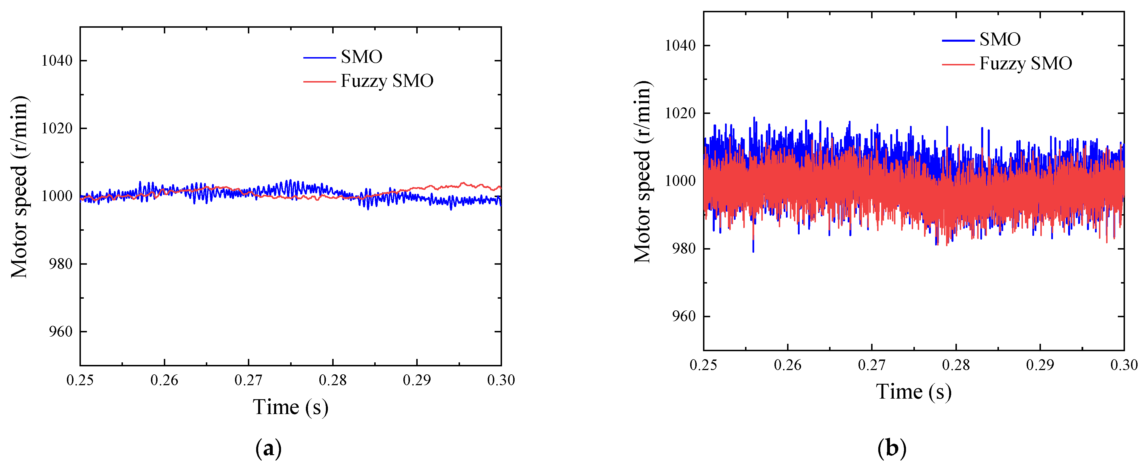
Comparison of speed between traditional SMO and new fuzzy SMO. (a) Simulation conditions. (b) Under experimental conditions.

Figure 20.
Comparison of rotor position between traditional SMO and new fuzzy SMO. (a) Simulation conditions. (b) Under experimental conditions.
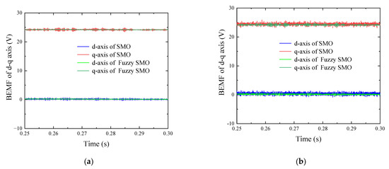
Figure 21.
Comparison of BEMF between traditional SMO and new fuzzy SMO. (a) Simulation conditions. (b) Under experimental conditions.
It can be seen that compared to the simulated environment, the actual environment has higher speed oscillation and lower rotor position accuracy. This is because in the simulation environment, the motor is influenced by the ideal power supply and controller, and there are no unexpected factors such as friction and inertia inside the motor, so the control effect is better. However, in actual operating environments, compared to traditional SMO, the new fuzzy SMO has smaller speed fluctuations and higher rotor position accuracy, which is consistent with simulation results. The experimental results validate the effectiveness of the new fuzzy SMO.
8. Conclusions
In this paper, a new type of fuzzy SMO is designed using a sigmoid (s) function with smooth and continuous characteristics instead of a discontinuous symbolic function, combined with the fuzzy control algorithm, to achieve adaptive sliding mode gain. Compared with traditional SMO, the new fuzzy SMO has a smoother curve and a rotational speed error of only 3 r/min, which does not change with changes in rotational speed or load, regardless of whether the operating conditions are in step speed or load conditions. Under the same operating conditions, compared with traditional SMO, the rotor position error is lower and the control accuracy is higher. In addition, in the case of sudden changes in speed and load disturbances, the overshoot is lower, and the system can respond faster and return to a predetermined value. The experimental results show that the new fuzzy SMO has a stronger ability to resist external interference and internal parameter changes, and has a faster response speed. The control performance of the system has been optimized, achieving the desired effect of the design.
Author Contributions
Conceptualization, G.Y. and Z.W.; methodology, Y.X.; software, X.W.; validation, G.Y., Z.W. and Y.X.; formal analysis, X.W.; investigation, X.W.; resources, X.W.; data curation, X.W.; writing—original draft preparation, X.W.; writing—review and editing, G.Y.; visualization, X.W.; supervision, X.W.; project administration, G.Y.; funding acquisition, G.Y. All authors have read and agreed to the published version of the manuscript.
Funding
This work was supported in part by the National Natural Science Foundation of China under grant no. 52066008, the Development of a Domestic Electronic Control System (ECU) for the China VI diesel engine under grant no. 202104BN050007, the Key Technology Research and Development of a methanol/diesel dual fuel engine under grant no. 202103AA080002, and the Research and Application of Key Technologies for extended-range commercial electric vehicles under grant no. 202102AC080004.
Data Availability Statement
Data are available upon request from the authors.
Conflicts of Interest
The authors declare no conflict of interest.
References
- Sato, D.; Itoh, J. Open-loop control for permanent magnet synchronous motor driven by square-wave voltage and stabilization control. In Proceedings of the IEEE Energy Conversion Congress and Exposition, Milwaukee, WI, USA, 18–22 September 2016; pp. 1–8. [Google Scholar]
- Shen, J.; Cai, J.; Miao, D.; Shi, D.; Miao, D.; Wang, Y.; Miao, D. Square-wave drive for synchronous reluctance machine and its torque ripple analysis. CES TEMS 2021, 5, 273–283. [Google Scholar] [CrossRef]
- Wu, M.; Zhao, R. Method analysis and comparison of SVPWM and SPWM. In Proceedings of the 29th Chinese Control Conference, Beijing, China, 29–31 July 2010; pp. 3184–3187. [Google Scholar]
- Tahmaz, O.; Ekim, M.; Yildiz, A. Vector Control of Permanent Magnet Synchronous Motor by a Two-Level SPWM Inverter. In Proceedings of the 2020 4th International Symposium on Multidisciplinary Studies and Innovative Technologies (ISMSIT), Istanbul, Turkey, 22–24 October 2020; pp. 1–7. [Google Scholar]
- Adamczyk, M.; Orlowska-Kowalska, T. Postfault Direct Field-Oriented Control of Induction Motor Drive Using Adaptive Virtual Current Sensor. IEEE Trans. Ind. Electron. 2021, 69, 3418–3427. [Google Scholar] [CrossRef]
- Deng, T.; Su, Z.; Lin, J.; Tang, P.; Chen, X.; Liu, P. Advanced Angle Field Weakening Control Strategy of Permanent Magnet Synchronous Motor. IEEE Trans. Veh. Technol. 2019, 68, 3424–3435. [Google Scholar] [CrossRef]
- Li, Z.; Zhou, S.; Xiao, Y.; Wang, L. Sensorless Vector Control of Permanent Magnet Synchronous Linear Motor Based on Self-Adaptive Super-Twisting Sliding Mode Controller. IEEE Access 2019, 7, 44998–45011. [Google Scholar] [CrossRef]
- Saleh, K.; Sumner, M. Sensorless Control of a PMSM Drive Post an Open Circuit Failure Based on 3D-SVPWM Technique. IEEJ Trans. Electr. Electron. Eng. 2022, 17, 1072–1082. [Google Scholar] [CrossRef]
- Qi, F.; Deng, Z.; Qiu, Z.; Wang, X. Sensorless technology of permanent magnet synchronous motors based on MRAS. Trans. China Electro-Tech. Soc. 2007, 22, 53–58. [Google Scholar]
- Feng, W.; Bai, J.; Zhang, Z.; Zhang, J. A Composite Variable Structure PI Controller for Sensorless Speed Control Systems of IPMSM. Energies 2022, 15, 8292. [Google Scholar] [CrossRef]
- Xu, Z.; Zhang, J.; Zhang, Y.; Zhao, J. Winding condition monitoring for inverter-fed pmsm using high-frequency current injection. IEEE Trans. Ind. Appl. 2021, 57, 5818–5828. [Google Scholar] [CrossRef]
- Kakihara, M.; Takaki, M.; Ohto, M.; Morimoto, S. An Investigation of Servo Motor Structure for Sensorless Control Based on High-Frequency Injection Method. In Proceedings of the 2020 23rd International Conference on Electrical Machines and Systems (ICEMS), Hamamatsu, Japan, 24–27 November 2020; pp. 912–917. [Google Scholar]
- Li, Q.; Wang, D.; Zhang, P.; Jin, Y.; Yang, B.-W.; Liao, J.-M. Speed estimation method based on extended Kalman filter with phase voltage compensation for sensorless ACIM drives. Electr. Mach. Control. 2019, 23, 35–44. [Google Scholar]
- Carlos, M.-E.; Daniel, H.-P.; Gross, G.; Marc, L.-M.; Daniel, M.-M. Maximum torque- per voltage flux-weakening strategy with speed limiter for PMSM drives. IEEE Trans. Ind. Electron. 2021, 68, 9254–9264. [Google Scholar]
- Shi, W.; Qi, R. Parameter identification of permanent-magnet motor thermal network based on extended kalmanfilte. J. Electr. Mach. Control. 2020, 24, 112–116. [Google Scholar]
- Jin, N.; Wang, X.; Wu, X. Current Sliding Mode Control with a Load Sliding Mode Observer for Permanent Magnet Synchronous Machines. J. Power Electron. 2014, 14, 105–114. [Google Scholar] [CrossRef]
- Dai, Y. Research on Position Sensorless Vector Control System for High Speed Permanent Magnet Synchronous Motor. Master’s Thesis, Harbin Institute of Technology, Harbin, China, 2011. [Google Scholar]
- Qiao, Z.; Shi, T.; Wang, Y.; Yan, Y.; Xia, C.; He, X. New Sliding-Mode Observer for Position Sensorless Control of Permanent-Magnet Synchronous Motor. IEEE Trans. Ind. Electron. 2013, 60, 710–719. [Google Scholar] [CrossRef]
- Qiao, Z.L.I. Adaptive second-order sliding mode observer with parameter identification for PMSM sensorless vector control. Control. Decis. 2019, 3, 1385–1393. [Google Scholar]
- Huang, K.; Gao, L.; Huang, S.; Luo, D. A correction method of rotor positions for high-speed Permanent magnet synchronous motor based on the error correction of the current loop. Proc. CSEE 2017, 37, 2399–2491. [Google Scholar]
- Gu, C.; Wang, X.; Deng, Z. A rotor position estimated error correction method for high-speed permanent magnet synchronous motor based on dual-phase-locked-loop. Proc. CSEE 2020, 40, 960–962. [Google Scholar]
- Sreejith, R.; Singh, B. Sensorless Predictive Current Control of PMSM EV Drive Using DSOGI-FLL Based Sliding Mode Observer. IEEE Trans. Ind. Electron. 2021, 68, 5537–5547. [Google Scholar] [CrossRef]


Disclaimer/Publisher’s Note: The statements, opinions and data contained in all publications are solely those of the individual author(s) and contributor(s) and not of MDPI and/or the editor(s). MDPI and/or the editor(s) disclaim responsibility for any injury to people or property resulting from any ideas, methods, instructions or products referred to in the content. |
© 2023 by the authors. Licensee MDPI, Basel, Switzerland. This article is an open access article distributed under the terms and conditions of the Creative Commons Attribution (CC BY) license (https://creativecommons.org/licenses/by/4.0/).