Abstract
A dual-band (K/Ka) TE01/TE02 mode gyrotron traveling wave tube is presented in this article. To suppress parasitic oscillations, a lossy-dielectric-loaded interaction circuit is employed. The particle-in-cell simulation results show that when it operates in K-band, the operating mode is the TE01 mode, with a peak output power of 87.1 kW, a saturated gain of 42.74 dB, and a −3 dB bandwidth of 0.7 GHz, and when it operates in Ka-band, the operating mode is the TE02 mode, with a peak output power of 62 kW, a saturated gain of 60.76 dB, and a −3 dB bandwidth of 2 GHz. Moreover, in the operating frequency range of the Ka-band, the overall gain is greater than 57 dB. To meet the requirements of dual-band operating, a dual-state magnetic injection gun is designed, a dual-mode coaxial cavity input coupler is proposed, and a dual-band output system is developed. All of these components showed excellent performance in simulations.
1. Introduction
The gyrotron traveling wave tube (gyro-TWT) is a vacuum electron amplifier based on the electron cyclotron maser mechanism [1,2,3]. With high power and wideband characteristics in millimeter wave and terahertz bands, the gyro-TWT has significant application prospects in areas such as high-resolution radars, high-speed communications, electronic countermeasures, and biomedicine [3,4]. Therefore, it has attracted many researchers to join the development of gyro-TWTs, and many outstanding research results have been reported. In Table 1, we list the basic performance parameters of recent research advances in gyro-TWTs. Amon them, ref. [5] reported a W-band second electron cyclotron harmonic helically corrugated waveguide (HCW) gyro-TWT with a continuous-wave (CW) output power of over 3 kW, a bandwidth of 2.5 GHz, an efficiency of 15%, and a gain of 54 dB. Meanwhile, a W-band broadband TE02 gyro-TWT with a periodic-dielectric-loaded (PDL) circuit is proposed in [6], which can achieve an output power of over 60 kW, a bandwidth of 8 GHz, and a saturated gain of 32 dB. It can be seen that harmonic interaction and higher-order mode operation are effective ways to ensure that the interaction structure and the electron channel have a large enough space. But, to some extent, that can also increase the mode competition. For increasing the power capacity and suppressing the mode competition, quasi-optical confocal and photonic-band-gap (PBG) circuits are proposed [7,8]. A 140 GHz confocal gyro-TWT was measured in 2009, and it can produce a peak power over 820 W with a −3 dB bandwidth of 0.8 GHz [7]. In addition, a 250 GHz PBG gyro-TWT was also designed and tested in 2013, with a short pulse of 260 ps, a gain of 38 dB, and an instantaneous bandwidth of 8 GHz [8]. Meanwhile, a G-band TE01 gyro-TWT with a traditional lossy circuit is reported in [9], and a particle-in-cell (PIC) simulation shows that it can achieve a saturated output power of over 10 kW and a bandwidth of 18 GHz. But, another challenge in the development of gyro-TWTs for sub-terahertz and terahertz bands is the shortage of pre-stage drive sources. To solve this problem, a sub-THz frequency-doubling gyro-TWT (FD-GTWT) is presented in [10], which shows for a 10 mW driving signal at 131.5 GHz an RF output power of 250 W at 263 GHz and a gain of >40 dB over a bandwidth of 17.5 GHz [10]. In this way, the shortage of pre-stage drive sources can be effectively alleviated.

Table 1.
Basic performance parameters of recent research advances in gyro-TWT.
Currently, most gyro-TWTs only work at a single frequency, which means their related applications cannot meet the cross-band work. To solve this problem, a dual-band operating gyro-TWT is proposed and studied. In 2012, a theoretical study of a Ka/V dual-band coaxial gyro-TWT was reported, which was predicted to provide a peak power of 375 kW with a 71 dB saturated gain and a 3.8 GHz bandwidth in the Ka-band and a peak power of 150 kW with a 35 dB saturated gain and a 1.7 GHz bandwidth in the V-band [11]. In addition, in 2014, a Ku/Ka dual-band gyro-TWA was proposed; in the Ku-band, it can generate a maximum output power of 238 kW with a −3 dB bandwidth of 1.5 GHz, and in the Ka-band, it can generate a maximum output power of 158 kW with a −3 dB bandwidth of 2.5 GHz. This type of dual-band gyro-TWT can effectively reduce the size, cost, and weight of a transmitter in dual-band radar and communication systems. Of course, other key components of the dual-band gyro-TWT, such as multi-state magnetron injection guns (MIGs), dual-mode input couplers, and dual-band output systems, have also attracted the interest of many researchers [13,14,15].
In this article, a K/Ka dual-band gyro-TWT with a lossy loaded circuit is demonstrated, and detailed analyses of the key components, including the interaction circuit, MIG, input coupler, and output system, are proposed. In Section 2, the basic principle of the dual-band gyro-TWT is analyzed by the small signal theory. In Section 3, the key components of the dual-band gyro-TWT, the MIG, input coupler, and output system, are proposed. In Section 4, a conclusion of this article is drawn.
2. Basic Theoretical Analysis of the Dual-Band Gyro-TWT
As shown in Figure 1, the dual-band TE01/TE02 mode gyro-TWT mainly consists of four key parts: a dual-state MIG with two emitters that can generate two different status cyclotron electrons, a dual-mode input coupler that can couple out two different modes (TE01 mode in the K-band and TE02 mode in the Ka-band), a lossy-dielectric-loaded beam–wave interaction circuit, and an output system (output gradual waveguide and three-disk output window) that is satisfied with the dual-band operation. In addition, the operating magnet system is composed of a compensating coil and a superconducting magnet, and it has a uniform field length of 450 mm. For this dual-band gyro-TWT, the operating modes are chosen as the TE01 and TE02 modes with a beam tunnel radius of 10.1 mm and corresponding cutoff frequencies of 18.11 GHz and 33.17 GHz, respectively. Meanwhile, due to the difference in lambda between the two bands, the gain per unit of the K-band is smaller than the Ka-band. So, to improve the K-band’s total gain, the K-band’s velocity ratio and beam current should be set larger than those of the Ka-band. The velocity ratio of the K-band electron beam is set as 1.2, and the velocity ratio of the Ka-band is set as 1.
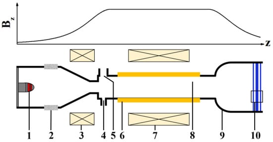
Figure 1.
Schematic configuration of the dual-band TE01/TE02 mode gyro-TWT and the operating magnetic field (1—dual-state MIG, 2—insulating ceramic, 3—compensating coil, 4—input port for Ka-band TE02 mode, 5—input port for K-band TE01 mode, 6—lossy dielectric, 7—superconducting magnet, 8—interaction space, 9—output gradual waveguide, 10—three-disk output window).
The loss dispersion curves of the dual-band gyro-TWT are shown in Figure 2. We can see that when it operates in the K-band, unwanted parasitic backward wave oscillations (BWOs) may occur at around 14.21, 15.56, and 33.34 GHz for the TE11, TE21, and TE02 modes, respectively, and when it operates in the Ka-band, the unwanted BWOs may occur at around 24.17, 24.85, 25.47, 27.61, and 31.76 GHz for the TE11, TE21, TE01, TE12, and TE22 modes, respectively. Meanwhile, the optimal guiding center radius can be obtained based on the small-signal theory. As shown in Figure 3a, when the and for TE02 and TE01, respectively, the interaction strength can be maximized. In addition, Figure 3b shows the relationship between the oscillation start-up current of two operating modes and the velocity ratio; when operating in the K-band with , the start-up current is about 5.35 A, and when operating in the Ka-band with , the start-up current is about 10.51 A. For suppressing the occurrence of operating mode oscillations, the beam currents are set as 4.5 A and 4 A for the K-band and Ka-band.
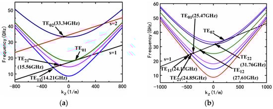
Figure 2.
(a) The loss waveguide dispersion curves of the dual-band gyro-TWT. Potential backward wave oscillations are marked with black dots. The corresponding modes and oscillation frequencies are also labeled. (a) K-band (beam voltage , velocity ratios , operating magnetic field ); (b) Ka-band (, , ).

Figure 3.
(a) The relationship between the coupling factor and guiding center radius . (b) The oscillation start-up current of two operating modes versus the velocity ratio.
Since the length of the loaded and unloaded circuits is closely related to the start-up length of the BWOs, it has the greatest impact on the performance of the gyro-TWT. Figure 4 shows the relationship between the potential BWOs’ start-up length and electron beam current. From Figure 4a, it can be seen that the minimum start-up length of the TE02 mode is ~96 mm when the beam current is 4.5 A. Figure 4b shows that the minimum start-up length of the TE22 mode is ~51 mm when the beam current is 4 A. Therefore, the length of the unloaded circuit is set to 48 mm to suppress the BWOs. Similarly, by theoretical analysis, we can obtain the minimum attenuation per centimeter required for the suppression of the TE11, TE21, TE01, TE12, TE21, and TE02 modes which is ~0.76, ~1.5, ~1.54, ~1.64, ~3.4, and ~2.11 dB/cm, respectively, when the effective beam–wave interaction circuit length is 430 mm. In this dual-band gyro-TWT, the lossy dielectric is chosen as Beo-Sic with a permittivity of . By changing the dielectric ceramic thickness, the circuit attenuation for different modes can be achieved. Through the small-signal theory analysis, we obtain the basic operating and structural parameters of the dual-band gyro-TWT. In the next section, we analyze the specific design of each component.

Figure 4.
The relationship between the potential BWOs’ start-up length and electron beam current. (a) TE11, TE21, and TE02 modes when gyro-TWT is operating in K-band. (b) TE11, TE21, TE01, TE12, and TE2 modes when gyro-TWT is operating in Ka-band.
3. The Key Component Design of the Dual-Band Gyro-TWT
3.1. Beam–Wave Interaction Circuit and PIC Simulation
As discussed in the previous section, proper attenuation can effectively suppress the parasitic oscillation and ensure the proper operation of the dual-band gyro-TWT. However, the presence of the attenuation dielectric will also have an attenuation on the operating mode, which in turn will affect the overall performance. Thus, we analyzed the attenuation of the operating mode in the lossy loading circuit in CST, and the results are shown in Figure 5. The final Beo-Sic dielectric thickness was determined to be 1.5 mm, which ensures sufficient attenuation to suppress oscillations while keeping the attenuation as small as possible for the TE02 mode and ensuring the processability of the dielectric ceramic.
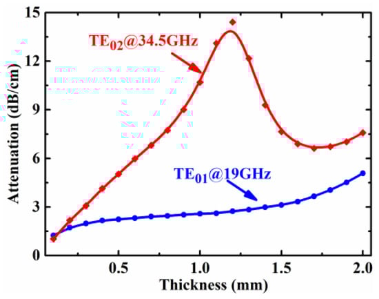
Figure 5.
The attenuation of operating modes TE01 and TE02 versus dielectric thickness.
To verify the rationality of the circuit design, a particle-in-cell (PIC) simulation study was carried out using MAGIC, and the basic parameters of the simulation are shown in Table 2. The simulation results of the dual-band gyro-TWT are shown in Figure 6, where the left (Figure 6a–d) and right (Figure 6e,f) sides are the results of the TE01 mode at 19 GHz and the TE02 mode at 34.5 GHz, respectively. From the E-field distribution in Figure 6a,e, it can be seen that the E-field strength of the operating mode reaches its maximum in the unloaded section. The corresponding spectrum in Figure 6d,h shows that no other parasitic modes appear and that the TE01 mode works at 19 GHz and the TE02 mode works at 34.5 GHz. Meanwhile, observing the electron beam trajectory in Figure 6b,f, we can find that at the rear of the interaction circuit, the clustering state of the electron beam gradually becomes stronger, thus achieving a large amount of energy. Figure 6c,g is the evolution of the output power, and it clearly shows that the output power can reach a stable output within 50 ns, whether operating in the K-band or Ka-band.
Table 2.
Beam–wave interaction parameters of dual-band gyro-TWT.

Figure 6.
The PIC simulation results of the dual-band gyro-TWT (the results of (a–d) are TE01 mode at 19 GHz, and the results of (e–h) are TE02 mode at 34.5 GHz). (a,e), The E-field distribution at the longitudinal section of the interaction circuit. (b,f), The electron beam trajectory. (c,g), Output power versus time. (d,h), Spectrum at the right output port.
Figure 7 shows the variation of output power and gain with the frequency of the dual-band gyro-TWT. It can be seen that the -3 dB bandwidth of K-band and Ka-band reaches ~0.7 GHz and ~2 GHz, the maximum power is 87.1 kW at 19.2 GHz and 62 kW at 33.6 GHz, corresponding to the efficiency of 32.26% and 27.6%, respectively. As can be seen from the gain curves in Figure 7b, the overall gain in Ka-band is greater than 57 dB, and the gain in K-band is smaller, due to the difference in gain per unit length, but the highest gain also reaches 42.74 dB at 19.2 GHz.

Figure 7.
The performance of the dual-band gyro-TWT is calculated by PIC simulation. (a) Output power versus frequency. (b) Output gain versus frequency.
3.2. Scheme of the Dual-State Triode MIG
The MIG is the main space to generate the cyclotron electron beam, and a high-quality electron beam can improve the performance of the gyro-TWT. The design of the MIG needs to consider the requirement for beam–wave interaction circuits. As discussed above, the radii of the electron-guided centers in the K-band and Ka-band are 0.48 and 0.2625 , respectively, and the operating magnetic fields are 0.68 Tesla and 1.25 Tesla, respectively. To design a MIG suitable for dual-band gyro-TWTs, the magnetic field compression ratio in Equation (1) was used to make predictions of the magnetic field and radius of the cathode emitter.
where is the magnetic field compression ratio, and and are the axial magnetic field at the cathode emitter and interaction circuit, respectively. is the cathode emitter radius, and is the Lamour radius of the cyclotron electron beam.
Figure 8 is the structure of the designed dual-state triode MIG. We can see that there are two emitters distributed on the cathode (the K-band emitter is the red one and the Ka-band emitter is the green one) with magnetic fields of 0.103 Tesla and 0.197 Tesla, respectively, and corresponding compression ratios of 6.6 and 6.35. In this case, the radii of the emitter of the K-band and Ka-band are 12.21 mm and 6.6 mm, respectively. Based on the above analysis, the dual-state MIG was initially designed and optimized by MAGIC. The optimized parameters are given in Table 3. This satisfies the requirements of beam–wave interaction, and the longitudinal velocity dispersions are all less than 5%.

Figure 8.
Structure of the dual-state triode MIG with two emitters.
Table 3.
Beam–wave interaction parameters of dual-band gyro-TWT.
3.3. Dual-Mode Input Coupler with Coaxial Cavity
An input coupler transmits the external drive signal into the beam–wave interaction circuit. Usually, the coupler should have a wide bandwidth, high transmission coefficient, and high mode purity. In this section, a dual-mode input coupler is designed for the dual-band gyro-TWT. Figure 9a shows the 3D structure of the dual-mode input coupler; to successfully achieve double band operating, standard rectangular waveguides of both the K- and Ka-bands were set as two input ports on both sides of the coaxial cavity, and the TE10 mode was used as the input mode. At the same time, a Bragg reflector was added to the K-band rectangular waveguide, thus preventing the propagation of high-frequency fields from the low-frequency input port, when it is operating in the Ka-band. Figure 9b shows the S-parameters of the Bragg reflector and the E-field distribution at 19 GHz and 34.5 GHz. The E-field distribution shows that the TE10 mode is successfully transmitted at 19 GHz and is essentially in the cutoff state at 34.5 GHz. Meanwhile, it can be seen that in the K-band (18–22.5 GHz), the S21 parameter is almost zero, and the S11 parameter is smaller than −10 dB, and in the Ka-band (33–36 GHz), the S11 parameter is bigger than −1 dB, and the S21 parameter is smaller than −10 dB in the full frequency band, which is consistent with the display of electric field distribution. Eventually, the external drive signal enters the interaction circuit through the coupling slit of the coaxial cavity, thus coupling out the operating mode.
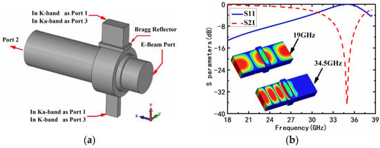
Figure 9.
(a) The 3D structure of the dual-mode coaxial cavity input coupler. (b) The Bragg reflector S-parameters and the E-field distribution of 19/34.5 GHz TE10 mode.
Figure 10 is the S-parameters and E-field distribution of the dual-mode coaxial cavity input coupler. As shown in Figure 10a, when operating in the K-band, the S21 parameter of the TE10-TE01 mode is bigger than −3 dB in the range of 18.5 GHz to 20.5 GHz, the S11 parameter is less than −10 dB, and the S21 parameters of other modes are less than −25 dB. From the E-field distribution diagram, it can be seen that the TE01 mode is successfully excited in the interaction circuit. Meanwhile, in Figure 10b, the S21 parameter of the TE10-TE02 mode is bigger than −3 dB in the range of 33.65 GHz to 35.5 GHz, and the S21 parameters of other modes are less than −15 dB, which are successfully suppressed. At the same time, the TE02 mode excited in the interaction waveguide is also shown in the E-field distribution diagram. The performance of this dual-mode input coupler successfully meets the requirements of beam–wave interactions.

Figure 10.
The S-parameters and E-field distribution of the dual-mode coaxial cavity input coupler. (a) TE01 mode is excited in K-band. (b) TE01 mode is excited in K-band.
3.4. Output System
The output gradual waveguide of the gyro-TWT is a device that transmits the high-power microwave signal after the interaction into the load through the output window. Generally, there is an inevitable problem of local reflection in the tapering section. Minimizing the reflections in the output gradual section to ensure the purity of the mode is an important goal in the design of the output gradual section. In this paper, the Dolph–Chebychev waveguide structure is used, which has significantly better impedance matching for each mode than the conventional linear gradual waveguide and sinusoidal waveguide.
The radius variation law of the Dolph–Chebychev gradual waveguide can be described by the following integral equation:
where is the Dolph–Chebychev distribution function, is the radius of the left boundary which is equal to the interaction circuit radius, is the radius of the right boundary, is the vacuum wavenumber, is the first-order derivative root of the m-order Bessel function, is the first-order derivative root of the n-order Bessel function, is the 0-order Bessel metamorphism, and is the boundary value of the Dolph–Chebychev distribution and is determined by the ratio of the operating mode conversion to parasitic modes.
The gradual structure satisfying the Dolph–Chebychev distribution law is obtained by a numerical integration program with , , and , and the calculated length of the gradual waveguide is ~103 mm. The corresponding model is optimized and simulated in CST, and optimization results are shown in Figure 11. From the two E-field distribution diagrams shown in Figure 11a,c, we can see that both the TE01 mode at 19 GHz and the TE02 mode at 34.5 GHz are successfully transmitted by the Dolph–Chebychev gradual waveguide. Meanwhile, as shown in Figure 11b,d, the transmission coefficient of the TE01 mode is bigger than −0.5 dB when the frequency is above 18.3 GHz, and the transmission coefficient of the TE02 mode is bigger than −0.5 dB when the frequency is above 33.3 GHz. The reflection is effectively suppressed. Although, in the TE02 mode transmission process, part of the energy is transformed to the TE01 mode, and the S21 parameter of the TE02-TE01 mode is still smaller than −15 dB, which can be neglected.
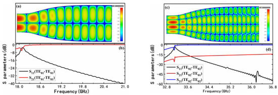
Figure 11.
Simulation results of the Dolph–Chebychev gradual waveguide. (a) The E-field distribution of TE01 mode at 19 GHz (b) The transmission coefficients of TE01 mode (c) The E-field distribution of TE02 mode at 34.5 GHz. (d) The transmission coefficients of TE02 mode.
In addition to the output gradual waveguide, the output window also plays an important role in the output system. Usually, the thickness of the output window of a gyro-TWT is an integer multiple of the half-wavelength of the EM-wave, which satisfies the following relationship:
where is a positive integer, and is the wavelength in the output window. To meet the output demands of the dual-band gyro-TWT, the output window needs to be designed to meet both the output of microwaves in the range of 18–20 GHz and the output of microwaves in the range of 33.5–35.5 GHz. Since the wavelengths of the two operating frequency bands are not integer multiples, the output window needs to have a wide enough bandwidth for meeting the dual-band gyro-TWT demands. So, a three-disk window with a good impedance matching over a wide frequency range is chosen, as shown in Figure 12. The material of the ceramic disk is 99.5% of Al2O3 which has high mechanical strength. Meanwhile, the thickness of the ceramic disk is set at 2.62 mm, and the spacing of the ceramic disk is set at 10.5 mm. The optimized model is simulated in CST, and the results are shown in Figure 13a,b; in the operating range of the K-band, the reflection coefficient stays smaller than −10 dB, and in the operating range of the Ka-band, the reflection coefficient stays smaller than −15 dB, completely meeting the design requirements of the dual-band gyro-TWT.

Figure 12.
The 3D structure of the three-disk output window.

Figure 13.
The S-parameters of the three-disk output window. (a) The K-band case with the E-field distribution at 19 GHz. (b) The Ka-band case with the E-field distribution at 34.5 GHz.
Figure 7 shows the variation in output power and gain with the frequency of the dual-band gyro-TWT. It can be seen that the −3 dB bandwidth of the K-band and Ka-band reaches ~0.7 GHz and ~2 GHz, and the maximum power is 87.1 kW at 19.2 GHz and 62 kW at 33.6 GHz, corresponding to the efficiency of 32.26% and 27.6%, respectively. As can be seen from the gain curves in Figure 7b, the overall gain in the Ka-band is greater than 57 dB, and the gain in the K-band is smaller, due to the difference in gain per unit length, but the highest gain also reaches 42.74 dB at 19.2 GHz.
3.5. Discussion
After the above design and analysis, we obtained the performance parameters of the key components of the dual-band gyro-TWT, as shown in Table 4. From this table, it can be seen that the effective operating frequency band of the beam–wave interaction circuit is 18.5–19.5 GHz in the K-band and 33.6–35.6 GHz in the Ka-band. The beam–wave interaction circuit is the core of the gyro-TWT; the other components need to satisfy its working requirements and ensure high-enough transmission efficiency. Observing the operating bands of other key components, it can be found that they are essentially larger than the interaction circuit’s operating frequency band, which can satisfy the requirements of the dual-band gyro-TWT. At the same time, the transmission coefficient of each component is >−3 dB, >−2.5 dB, and >−0.5 dB, respectively, which means that the whole transmission efficiency is greater than −6 dB, and the reflection coefficients are kept at a low level, which does not affect the operating performance.
Table 4.
Key components’ performance of the dual-band gyro-TWT.
Meanwhile, in Table 5, we compare the performance parameters of the existing dual-band gyro-TWT and the dual-band gyro-TWT designed in this paper. Although the maximum output power is slightly inferior, which is caused by the smaller electron current, it shows outstanding performance in terms of efficiency and gain. Even after considering the transmission loss of other components, the gain is still greater than 36 dB in the K-band and 54 dB in the Ka-band. Of course, the bandwidth has some shortcomings, and it is hoped that the bandwidth can be further optimized in subsequent work.
Table 5.
Comparison between the designed dual-band gyro-TWT and other reported dual-band gyro-TWTs.
4. Conclusions
In this article, a dual-band TE01/TE02 mode gyro-TWT is presented. The PIC simulation predicts that the dual-band gyro-TWT can generate a peak output power of 87.1 kW with a saturated gain of 42.74 dB and a −3 dB bandwidth of 0.7 GHz in the K-band and a peak output power of 62 kW with a saturated gain of 60.76 dB and a −3 dB bandwidth of 2 GHz in the Ka-band. Meanwhile, over the entire operating bandwidth of the Ka-band, in the range of 33.5 GHz–35.5 GHz, the overall gain is greater than 57 dB. To meet the demands of the dual-band gyro-TWT, a dual-state MIG with two emitters is demonstrated: it can generate an electron beam with a velocity ratio of 1.2, a beam current of 4.5 A, and a guiding center radius of 0.48 and an electron beam with a velocity ratio of 1, a beam current of 4 A, and a guiding center radius of 0.2625 , respectively. A dual-mode coaxial cavity input coupler is proposed, and it can efficiently couple out the TE01 mode in the frequency range of 18.5–20.5 GHz and the TE02 mode in the frequency range of 33.65–35.5 GHz, respectively. In addition, a dual-band output system is presented, including a Dolph–Chebychev gradual waveguide and a three-disk output window; the former can efficiently transmit a TE01 mode greater than 18.3 GHz and a TE02 mode greater than 33.3 GHz, and the latter has a transmission frequency range of 17–20.2 GHz and 33.5–36 GHz for the TE01 and TE02 modes, respectively. The performances of these designed components are consistent with the requirements of the beam–wave interaction requirements. Since the design of the currently available dual-band gyro-TWTs is only in the state of theoretical research, in the next step, we will process and test the components to verify the practicability of this type of dual-band gyro-TWT.
Author Contributions
Conceptualization, R.C. and Q.Z.; methodology, R.C.; software, R.C. and S.Y.; validation, R.C., T.Z. and Q.Z.; formal analysis, R.C., T.Z. and Q.Z.; investigation, R.C., T.Z., Q.Z. and S.Y.; resources, T.Z.; data curation, R.C. and Q.Z.; writing—original draft preparation, R.C. and Q.Z.; writing—review and editing, R.C. and T.Z.; visualization, Q.Z.; supervision, S.Y.; project administration, R.C.; funding acquisition, R.C. All authors have read and agreed to the published version of the manuscript.
Funding
This research received no external funding.
Data Availability Statement
All data included in this study are available upon request by contacting the corresponding author.
Conflicts of Interest
The authors declare no conflict of interest.
References
- Chu, K.R. The electron cyclotron maser. Rev. Mod. Phys. 2004, 76, 489. [Google Scholar] [CrossRef]
- Booske, J.H.; Dobbs, R.J.; Joye, C.D.; Kory, C.L.; Neil, G.R.; Park, G.; Park, J.; Temkin, R.J. Vacuum Electronic High Power Terahertz Sources. IEEE Trans. Terahertz Sci. Technol. 2011, 1, 54–75. [Google Scholar] [CrossRef]
- Nusinovich, G.S.; Thumm, M.K.A.; Petelin, M.I. The Gyrotron at 50: Historical Overview. J. Infrared Millim. Terahertz Waves 2014, 35, 325–381. [Google Scholar] [CrossRef]
- Sabchevski, S.; Glyavin, M.; Mitsudo, S.; Tatematsu, Y.; Idehara, T. Novel and Emerging Applications of the Gyrotrons Worldwide: Current Status and Prospects. J. Infrared Millim. Terahertz Waves 2021, 42, 715–741. [Google Scholar] [CrossRef]
- Samsonov, S.V.; Denisov, G.G.; Gachev, I.G.; Bogdashov, A.A. CW Operation of a W-band High-Gain Helical-Waveguide Gyrotron Traveling-Wave Tube. IEEE Electr. Device Lett. 2020, 41, 773–776. [Google Scholar] [CrossRef]
- Zeng, X.; Du, C.; Li, A.; Gao, S.; Wang, Z.; Zhang, Y.; Zi, Z.; Feng, J. Design and Preliminary Experiment of W-Band Broadband TE02 Mode Gyro-TWT. Electronics 2021, 10, 1950. [Google Scholar] [CrossRef]
- Joye, C.D.; Shapiro, M.A.; Sirigiri, J.R.; Temkin, R.J. Demonstration of a 140-GHz 1-kW Confocal Gyro-Traveling-Wave Amplifier. IEEE Trans. Electron. Dev. 2009, 56, 818–827. [Google Scholar] [CrossRef] [PubMed]
- Nanni, E.A.; Lewis, S.M.; Shapiro, M.A.; Griffin, R.G.; Temkin, R.J. Photonic-Band-Gap Traveling-Wave Gyrotron Amplifier. Phys. Rev. Lett. 2013, 111, 235101. [Google Scholar] [CrossRef] [PubMed]
- Liu, G.; Cao, Y.; Wang, Y.; Jiang, W.; Wang, W.; Wang, J.; Luo, Y. Design and Cold Test of a G-Band 10-kW-Level Pulse TE01-Mode Gyrotron Traveling-Wave Tube. IEEE Trans. Electron. Dev. 2022, 69, 2668–2674. [Google Scholar] [CrossRef]
- Marek, A.; Feuerstein, L.; Illy, S.; Thumm, M.; Wu, C.; Jelonnek, J. New Type of Sub-THz Frequency-Doubling Gyro-TWT With Helically Corrugated Circuit. IEEE Electr. Device Lett. 2022, 43, 1347–1350. [Google Scholar] [CrossRef]
- Hung, C. High-power, stable Ka/V dual-band gyrotron traveling-wave tube amplifier. Appl. Phys. Lett. 2012, 100, 203502. [Google Scholar] [CrossRef]
- Tang, Y.; Luo, Y.; Xu, Y.; Yan, R.; Jiang, W.; Zheng, Y. Design of a Novel Dual-Band Gyro-TWT. IEEE Trans. Electron. Dev. 2014, 61, 3858–3863. [Google Scholar] [CrossRef]
- Dong, K.; Luo, Y.; Jiang, W.; Fu, H.; Wang, S. Magnetron Injection Gun Design for Multifrequency Band Operations. IEEE Trans. Electron. Dev. 2016, 63, 3719–3724. [Google Scholar] [CrossRef]
- Wang, X.; Gao, D.; Wang, Y.; Zhang, F. Novel double-band input coupler for gyroklystron and gyro-TWT. AIP Adv. 2021, 11, 45019. [Google Scholar] [CrossRef]
- Ma, M.; Zhao, Q.; Mo, K.; Zheng, S.; Peng, L.; Lv, Y.; Feng, J. Design of a Dual-Mode Input Structure for K/Ka-Band Gyrotron TWT. Electronics 2022, 11, 432. [Google Scholar] [CrossRef]


Disclaimer/Publisher’s Note: The statements, opinions and data contained in all publications are solely those of the individual author(s) and contributor(s) and not of MDPI and/or the editor(s). MDPI and/or the editor(s) disclaim responsibility for any injury to people or property resulting from any ideas, methods, instructions or products referred to in the content. |
© 2023 by the authors. Licensee MDPI, Basel, Switzerland. This article is an open access article distributed under the terms and conditions of the Creative Commons Attribution (CC BY) license (https://creativecommons.org/licenses/by/4.0/).